Windows - Darcoid
Windows - Darcoid
Windows - Darcoid

You also want an ePaper? Increase the reach of your titles
YUMPU automatically turns print PDFs into web optimized ePapers that Google loves.
E. WINDOWSPRODUCTPAGEWINDOWS DESIGN GUIDE . . . . . . . . . . . . . . . . . . . . . . . . . . . . . . . . . . . . . . . . . . . . . . . . . . .E1 - E17ECTC . . . . . . . . . . . . . . . . . . . . . . . . . . . . . . . . . . . . . . . . . . . . . . . . . . . . . . . . . . . . . . . . . . .E19 - E20TECKFILM . . . . . . . . . . . . . . . . . . . . . . . . . . . . . . . . . . . . . . . . . . . . . . . . . . . . . . . . . . . . . . . . . . . .E21TECKSHIELD F . . . . . . . . . . . . . . . . . . . . . . . . . . . . . . . . . . . . . . . . . . . . . . . . . . . . . . . . . . . . . . . .E22TECKSHIELD F: POLYCARBONATE WINDOWS . . . . . . . . . . . . . . . . . . . . . . . . . . . . . . . . . . . . . . . .E23TECKSHIELD F: ALLYCARBONATE WINDOWS . . . . . . . . . . . . . . . . . . . . . . . . . . . . . . . . . . . . . . . . .E24Mexico: 528-18-369-8610 • China: 86-10-67884650 • www.tecknit.com
E. WINDOWSU.S. Customary[SI Metric]Design Guidelines toEMI Shielding <strong>Windows</strong>INTRODUCTIONThe DESIGN GUIDELINES TO SHIELDING WIN-DOWS is intended to aid designers in understandingthe trade-offs associated with the selectionof specific materials against anticipatedperformance.One of the many requirements, which compromisethe shielding integrity of equipment enclosures,is the need for large-area openings foraccess to electronics, ventilation, and displays.The displays may be panel meters, digital displays,oscilloscopes, status monitors, mechanicalindicators or other read-outs. The most criticaldisplays to shield against electronic noise are thelarge area, high resolution monitors (CRT).Shielding of these large apertures is generallymore difficult than those encountered for coverplates, doors, ventilation panels and small apertures,such as connectors, switches and othercontrols in which the majority of the opening iscovered by a continuous homogeneous conductive(metal) plate. Therefore, when working withwindow designs, which do not have a continuousconductive cover, consideration must be given toshielding as related to relative apertures andscreens and supporting substrates. These twofactors are inter-related and need to be treated asa combined problem.Shielding windows are presently manufactured inone of three ways: (1) laminating a conductivescreen between optically clear plastic and glasssheets; (2) Casting a screen within a plasticsheet; (3) applying an optically clear conductivelayer to a transparent substrate. Until recently,the typical conductive screen was a knitted wiremesh made from Monel, tin-plated copper-cladiron core (Sn/Cu/Fe or Monel wire).Knitted densities range from 30 openings perinch for the 0.001-inch diameter tungsten wire(94% open area) to 10 openings per inch for the0.0045-inch diameter wire (90% open area).These high open area meshes provide high opticaltransmission with average shielding effectiveness(greater than 60 dB) below 10 MHz whenwire crossovers are adequately bonded.Optically clear conductive coatings are producedby depositing an electrically conductive transparentcoating (ECTC) directly onto the surface ofvarious optical substrates. Typically, these coatingscan provide better than 50 dB shieldingeffectiveness below 100 MHz with an opticaltransmission of better than 70% over the visiblelight spectrum. Increased shielding effectivenessmay be achieved by increasing the thickness ofthe deposited coating material (decreasing resistance)at the expense of loss in optical transmissionand increase in optical reflection.High-density woven wire screens have beenemployed which have extended the useful highfrequencyresponse beyond 10GHz. Thesescreens have made use of silver-plated, stainlesssteel wires; copper-plated, stainless steel wires;and copper wires. In all cases these screensmake direct contact to a peripheral wire meshgasket, window frame or enclosure structure.Woven meshes have ranged from 80 mesh (wiresto the inch) to 150 mesh and wire diameters from0.001 inch diameter to 0.0045 inch diameter.Typical performance for a 100 mesh screen willprovide almost 60% open area with shieldingeffectiveness of up to 60 dB beyond 1 GHz.Higher mesh densities and large wire diametersusually result in higher shielding effectivenesswith lower optical performance.In the following sections, various aspects ofshielding window design will be reviewed as relatedto shielding performance, optical performance,optical designs and methods for mounting windowsto enclosures.E-1U.S.A.: 908-272-5500 • U.K.: 44-1476-590600 • Spain: 34-91-4810178
E. WINDOWSSHIELDING PERFORMANCEA great deal of information has been written andpublished on total shielding effectiveness (SE) asan aid in reducing electromagnetic interference(electrical noise). Electromagnetic compatibility(EMC) may be achieved by reducing the electromagneticinterference (EMI) below the thresholdlevel that disrupts the normal operation of anelectronic system. An electronic system can beboth an emitter and a susceptor. An EMI emittergenerates unwanted noise; a susceptor respondsto unwanted noise. Military and governmentalspecifications stipulate the allowable levels ofradiated and conducted emissions and the necessarycircuit immunity to these emissions toachieve electromagnetic compatibility (EMC).Shielding requirements for shielding windows canvary from moderate to severe. Any barrier placedbetween an emitter and a susceptor that diminishesthe field strength of the interference is anEMI shield. The attenuation of the electromagneticfield is referred to as its shielding effective(SE). The standard unit of measurement forshielding effectiveness is the decibel (dB). Thedecibel is expressed as the ratio of electromagneticfield strength on one side of a shielding barrierto the field strength on the opposite side.emitter to the shield. Figure 2-1 depicts the relationshipbetween decibels, attenuation ratio, andpercent attenuation.In most shielding applications, shielding effectivenessbelow 20 dB (10:1 reduction in EMI) is consideredmarginal due to long-term environmentaleffects on the mating surfaces of enclosures andshielding gaskets and barriers. Normally, acceptableshielding performance covers the range from30 dB to 80 dB. Above average shielding rangesfrom 80d dB to 120 dB. Above 120 dB, shieldingeffectiveness is difficult to achieve and difficultto confirm by measurement.Figure 2-2 shows the range of shielding effectivenessfor the three primary barrier materials usedin shielding window: knitted wire mesh screens(Band I), transparent conductive coatings (BandII), and woven mesh screens (Band III).Shielding performance is the primary considerationin the design process and is, therefore, consideredfirst.The losses in field strength (absorption andreflection) from a shield are functions of the barriermaterial properties: permeability, conductivity,and thickness, as well as the distance from theFigure 2. Shielding Effectiveness as a Function of Attenuation.Figure 2-2. Barrier Shielding Performance for Shielding<strong>Windows</strong>.Mexico: 528-18-369-8610 • China: 86-10-67884650 • www.tecknit.comE-2
E. WINDOWSDesign Guidelines toEMI Shielding <strong>Windows</strong> cont.U.S. Customary[SI Metric]The shielding values presented in Figure 2-2 areconsidered to be conservative based on measurementsin shielded room tests, which generallyshow from 10 dB to 20 dB higher shielding effectiveness.The origin of the data is based on thetheoretical relationship given by:SE dB = 195-20 log 10 (df)Where d is the mesh wire spacing in inches and fis the threat frequency in Hertz.Since most EMI problems are broadband (cover abroad frequency range), the frequency of mostconcern is generally the highest frequency withinthat bandwidth envelope to which the equipmentis responsive and which may be a threat to electromagneticcompatibility. Therefore, the highestthreat frequency and the shielding requirementsat that frequency are both needed to determinethe type or types of windows, which are suitablefor that application.For example, assume the highest threat frequencyis 10 MHz with a maximum required shieldingof 60 dB at that frequency. Figure 2-2 shows thatany of the three families of shielding materialswould be suitable to provide of shielding materialswould be suitable to provide adequate shielding.On the other hand, changing the maximum threatfrequency from 10 MHz to 100 MHz wouldeliminate the knitted wire mesh screens and thetransparent conductive coatings, leaving only thehigh-performance woven screens as a suitablesolution.Knowing which types of windows are available,the next selection should be made on the basis ofthe optical transmission that is attainable from thescreen materials or conductive coatings, plus theoptical substrate. Standard optical substratesshould cause only a minor reduction in opticaltransmission should be less than 1% to up to10%, depending upon the reflection and absorptionfrom coated and uncoated surfaces of thesubstrates. The following section will deal withthe evaluation of the windows from an opticalaspect of the specific materials to be referred toas percent open area. This characteristic isimportant in determining optical contrast whichcan affect operator fatigue in using devices suchas video display monitors.Table 2-1 summarizes the general shielding effectivenessranges at specific frequencies for thethree shielding materials shown in Figure 2-2.The three frequencies are 1 MHz (magneticfield), 10MHz (electric field), and 1 GHz (planewave).SUMMARYFigure 2-1. Shielding PerformanceShielding Screen MaterialShielding Range (dB)Magnetic Electric Plane1 MHz 10MHz 1GHzI Knitted Wire Mesh 30-40 60-70 20-25(Monel-Cross over Bond)10-30 CPIII Transparent Conductive 40-50 70-80 30-40Coating8 to 24 OHM/SquareIII Woven WireMesh 65-75 95-110 60-70(Copper Wire)80-200 meshE-3U.S.A.: 908-272-5500 • U.K.: 44-1476-590600 • Spain: 34-91-4810178
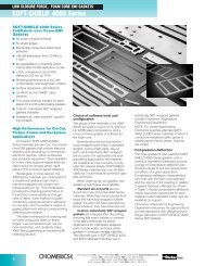
E. WINDOWSOPTICAL PERFORMANCETo deal with the material selection process anunderstanding of optical properties of shieldingwindows is imperative. These properties concernthe optical transmission of the finished window,including optical substrate, shielding screen, laminatingmaterial, coatings, and characteristics oftransmission color filters. This section discussesthe optical performance of the shielding screens.Knitted mesh screens are produced on industrialknitting machines that were originally developedfor the commercial, knitted fabric materials industry.The machines have been adapted to handlewire instead of yarn. In this process they producea continuous tube of material called a “stocking.”The diameter of the stockings varies from 3/8inch to 30 inches. Various sizes are used tomake electrically conductive metal gaskets andthe conductive mesh screens for shielding windows.The irregular shapes formed in the knittingprocess (see Figure 3-1) aid in minimizing anyobscuration of regular shapes as might be formedin typed or printed information. The density ofthe mesh is determined by the courses per inchalong the length of the stocking, the wire materialand the wire diameter. To maintain a square patternof openings in both directions, it is necessaryto call out the number of openings per incharound the stocking as well. This effectivelydetermines the complete description of the knittedmesh screen. Knitted screens are generallylimited to about 30 openings per inch when usedas a screen for shielding windows.wires per inch). Typical wire diameters vary from0.001 inch to 0.0025 inch depending upon platingand blackening. Blackening of the screenreduces reflections and improves image contrast.Figure 3-2. Woven Mesh Screens.A third shielding material is the transparent conductivecoating. This material exhibits good shieldingproperties at moderate optical transparency (referenceTable 2-1 on shielding performance for knitted,woven and transparent conductive coatings). Sincethe shielding effectiveness is a function of the resistivityof the transparent coating which, in turn, is afunction of the optical transmission, there are tradeoffsin performance (see Figure 3-3 and Table 3-1).An optimum relationship for this type of coatingoccurs at approximately 10 to 14 ohms per surfaceresistivity to obtain approximately 70% transmissionand greater than 50 dB shielding at 100 MHz.Figure 3. Knitted Mesh Screens.Woven mesh using fine wires, generally muchsmaller than 0.005 inch diameter, provide a significantimprovement in shielding effectivenessover other shielding widow materials, even athigher frequencies. These woven screens have80 or more wires to the inch in both directions(Figure 3-2). Typical mesh density is 100 mesh(100 by 100 wires per inch), 120 mesh (120 by120 wires per inch) and 150 mesh (150 by 150Figure 3-3. Light Transmission-Resistivity Relationship (ThinGold Coating).Mexico: 528-18-369-8610 • China: 86-10-67884650 • www.tecknit.comE-4
E. WINDOWSU.S. Customary[SI Metric]E-5Design Guidelines toEMI Shielding <strong>Windows</strong> cont.Figure 3-4 provides a ready reference for the opticalTransmission (percent open area) of the three typesof shielding materials for windows covering the mostcommonly used knitted mesh screens, woven meshscreens and transparent conductive coatings. Thecommonly used materials are annotated by circle (O)on the figure.Figure 3-4. Percent Open Area of Mesh Screen.Section A of Figure 3-4 encompasses the usefulrange of knitted materials. Wire diameters from0.001 inch to 0.0045 inch bound the upper andlower limits while 10 to 25 CPI provide the limits ofmesh densities. These boundaries provide the highestoptical open area ranging from about 80% togreater than 95%. Bonding of wire crossovers hasbeen assumed in all performance data shown in thisguideline.Section B of Figure 3-4 depicts the useful range ofwoven screen materials ranging from wire diametersof 0.001 inch to 0.0045 inch and mesh densitiesFigure 3-1.from 80 to 200 mesh. The circles indicate commonlyused mesh materials that are generally readilyavailable. Performance for 100 mesh screen with0.0045 inch diameter copper wire provides approximately30% optical transparency and 70 dB shielding,while 100 mesh with 0.002 inch Diameter copperwire provides about twice the open area (64%)while reducing the shielding effectiveness by only 10to 12 dB.Section C of Figure 3-4 (vertical coordinate) showsthe normal range of transparency for the transparentconductive coating. These electrically conductivetransparent coatings (ECTC) have a distinct advantageover screen materials when used with threecolor CRT’s employing a color mask on the faceplate.The color mask is used to delineate the specificphosphor color to be displayed. The masks have acolor repetition pattern or pitch that varies from anequivalent mesh density of about 60 mesh for broadcastmonitors to 130 mesh for the very high-resolutionmonitors. Whenever a repetitive pattern, suchas a shielding mesh screen, is placed in front of acolor CRT, patterns of dark and light bars are knownas moiré patterns. They occur as a result of themesh screen having nearly the same pitch as thepattern of the CRT color mask. Rotating the meshwill vary the number of bars. Changing the numberof wires per inch (mesh density) will also alter thenumber of bars. Often there is an optimum meshdensity, wire size and angular relationship to thefixed CRT color mask pattern that will minimize oreven eliminate the interference pattern.These light and dark bars are the result of the patternsof two objects, either aligning up exactly witheach other to produce light areas or misaligningcompletely and blocking all transmitted light to producedark bars. Sometimes, it is difficult to attain aperfect match between the CRT mask and thescreen mesh. ECTC windows on the other hand donot have a repetitive structure similar to the shieldingmesh screens. They are, therefore, ideal in someapplications as an EMI shield for color monitors.The main limitations with the ECTC windows are highShielding Screen Material Shielding Range (dB) Optical Open Area (%)Magnetic Electric Plane1 MHz 10MHz 1GHz 0.001” DIA. 0.002’ DIA. 0.0045” DIA.I Knitted Wire Mesh 30-40 60-70 20-25 95-98% 90-96% 79-91%(Monel-Cross over Bond)10-30 CPIII Transparent Conductive 40-50 70-80 30-40 60-80% NA NACoating (Molecular8 to 24 OHM/Square Structure)III Woven WireMesh 65-75 95-110 60-70 64-86% 36-70% 30-41%(Copper Wire) 80-200 meshU.S.A.: 908-272-5500 • U.K.: 44-1476-590600 • Spain: 34-91-4810178
E. WINDOWScost, their tendency to be easily scratched, a noticeablecolor tint for some coatings and a lower shieldingeffectiveness than the woven mesh screens.The TECKNIT EMI Shielding Design Guide is anexcellent reference in determining the requiredshielding for specific specifications (MIL-STD-461,FCC, VDE and others) against equipment circuitsand EMI generators. Tables 3-1 summarize the performancecapabilities of shielding windows from bothshielding and optical aspects.OPTICALLY CLEAR WINDOW SUBSTRATESGlass and clear plastic optical substrate materials arethe most common for covering large area aperturesfor viewing windows. This section discusses thebasic properties of these materials for shieldingapplications requiring both flat and curved windows.GLASS SUBSTRATESGlass substrate materials provide the hardest surfacefor resistance to scratches and marring. Once fullylaminated, these windows closely match the propertiesof safety glass, with the added protection of anembedded screen mesh.Properties of the glass conform to ASTM-C-1036 andmirror to mirror select quality. Edges are cut andtrimmed to remove any sharp surfaces. Edges maybe ground, ground and polished, beveled, or miteredon special order as specified by customer drawingsor specifications. Standard glass window thicknessis 0.205 inch with a tolerance of plus or minus 0.020inch. Other thickness may be furnished in theranges and tolerances shown in Table 4-1.Maximum outside dimensions (length by width) are18 inches by 14 inches with a standard tolerance ofplus or minus 0.031 inch. Major defects such asgaseous inclusions, which are permitted by FederalSpecifications, are culled before laminating. Glass,in effect, when specified for shielding windows willexceed the requirements as stipulated in federalSpecifications. Plate glass is specified to assure virtuallyparallel and flat surfaces. See TECKSHIELD-FData Sheet for laminated glass windows.PLASTIC SUBSTRATESNot all-clear plastics are of use in the manufacture ofshielding windows. Plastics are divided into two generalclasses: thermoplastic and thermosetting resins.A thermoplastic material softens when heated andhardens on cooling. Since this action is reversible itis possible for the material to be molded and remoldedwithout appreciable change in the material properties.The significant difference in thermosettingmaterials is the irreversible heating action. Theselatter materials, once softened by heating, remain inthe shape formed during the original heating cycle.Hence, the desired or final shape of the windows tobe made must be incorporated into the mold of thepart. Furthermore, with thermosetting plastics, thedesired color) other than clear) depends on the thoroughblending of the proper mixture of the coloringagent with the plastic material before molding.THERMOPLASTICS-Cellulose Derivatives: The principalcellulose derivatives are the nitrate, acetate,acetate butyrate, and ethyl cellulose. The celluloseplastics have a comparatively poor surface hardnessand poor abrasive resistance. They are readilyhygroscopic (absorb water) with a resultant changein dimensions. Most do not possess the high opticalqualities of glass or some of the other plastic substratematerials. Softening occurs at about 60*C forthese thermoplastic materials and, therefore must beused in applications which will not exceed their softeningtemperature. Cellulose acetate butyrate (CAB)is probably the best of the cellulose family of plastics.It is especially suited to molding and possesseslower water absorption than other cellulose derivatesand therefore, betters dimensional stability than celluloseacetate.THERMOPLASTICS-Synthetic Resins: The principalthermoplastic resin materials consist of polycarbonates,polystyrenes and methyl methacrylates(acrylic). In general these resins are characterizedby higher resistance to chemicals and lower waterabsorption than the cellulose derivatives. They generallyhave optical characteristics very close to glasswith a much lower tendency toward scratching, butare still very much softer than glass. Polycarbonateis about 10 times easier to scratch or mar than themethyl methacrylates (acrylic).Polycarbonate material is virtually unbreakable andcan withstand impacts greater than 200 ft.-lbs. for aone eighth inch thick sheet. Softening temperatureis about 125*C. The poorer than desirable scratchperformance makes polycarbonate a poor candidatefor viewing windows that require periodic cleaning,such as may be needed with cathode ray tubes(CRT). Some aromatic solvents (hydrocarbon) causesurface stress cracking in this material.Polystyrene material is relatively hard and rigid, naturallycolorless and quite transparent. The softeningrange is about 20*C higher than the cellulose plastics,but lower than that for acrylic resins. Mostother properties for this material are excellent exceptfor poor resistance to most organic solvents.Methyl methacrylate (acrylic) material has high luster,high transparency, and good surface hardness, iscomparatively inert chemically and is not toxic.Essentially, acrylic possesses almost all the desirablequalities of glass except for scratch resistance. Compared to other plastics, methyl methacrylate is harderthan most but still readily scratched by dust particles.Methyl methacrylate is a very stable compound andretains to a high degree its mechanical propertiesunder adverse environmental conditions. Impactresistance when compared to some plastics ispoor, although when compared to glass it is muchsuperior.Mexico: 528-18-369-8610 • China: 86-10-67884650 • www.tecknit.comE-6
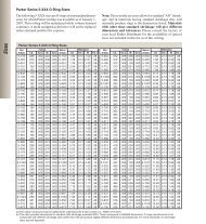
E. WINDOWSDesign Guidelines toEMI Shielding <strong>Windows</strong> cont.U.S. Customary[SI Metric]THERMOSETTING RESINS – ACP, CR-39 (PPG industries):ACP (Allyl Cast Plastic) is known as ColumbiaResin (CR-39). It is a transparent solid, cured fromthe clear, colorless, water-insoluble liquid monomerthrough the aid of a catalyst. It is strong, relativelyinsoluble and inert. It is normally free of internalhaze, has a low water absorption and moderate coefficientof thermal conductivity. Refractive index isalmost identical to that of crown glass, and yet, thedensity is about one-half. The resin material isSuperior to acrylic and other plastics with respect tosoftening under heat, crazing, resistance to abrasionand attach by chemicals. The continuous use temperatureis 100*C.In summary, the three most likely candidates foroptical substrate materials in shielding window applicationare glass, acrylic and CR-39, in that order.Table 4-2 summarizes the performance characteristicsof these materials.TABLE 4-1STANDARD SIZES AND TOLERANCESMATERIAL MAXIMUM SIZE TOLERANCE THICKNESS (Overall) REMARKSPlate Glass Standard ±0.031” Standard (1) Glass per ASTM-C-1036(woven mesh) 32” x 56” 0.270 ± 0.020 inch32” x 32” 0.205 ± 0.020 inchSpecialSpecial14” x 14” 0.145 ± 0.020 inchPlastic Standard ±0.031” Standard (acrylic) Acrylic per L-P-391(woven mesh) 24” x 24” 0.145 ± 0.020 inchSpecialSpecial (acrylic)32” x 32” 0.205 ± 0.020 inch32” x 56” 0.270 ± 0.020 inchPlastic 18” x 22” ±0.031” Standard (cast) (2) Smooth or matte finish,(knitted mesh 0.125±0.010 inch Polycarbonate CR-39,& ECTC) (4) Standard (edge laminated) (3) Acrylics0.135±0.015 inchSpecial (Cast)0.060±0.010 inch(1)TECKSHIELD-F Specification Reference, Appendix A-1(2)EMC-CAST Specification Reference, Appendix A-2(3)EMC-LAMlNATED Specification Reference, Appendix A-3(4)EMC-ECTC Specification Reference, Appendix A-4(5)Contact factory for larger edge bonded windows.E-7TABLE 4-2PROPERTIES OF WINDOW SUBSTRATES (TYPICAL VALUES FOR CLEAR COLORLESS MATERIAL)METHYLPLATE METHACRYLATE POLYCARBONATE (1) CR-39PROPERTY UNITS GLASS (ACRYLIC) (1)OPTICALIndex of refraction – 1.529 1.48-1.51 1.59 1.50-1.57Transmission % 90 21-23 85-89 89-91Haze % 0.9 0.6 0.5-2.0 0.4MECHANICALFlexure Strength psi 12-14,000 12-13,000 5,000Impact Strength (Izod Notch) ft-lb./in. 0.4 12-16 0.2-0.4Hardness Rockwell M80-M90 M68-M74 M95-M100Specific Gravity – 2.52 1.20 1.20 1.32ELECTRICALDielectric Strength volt/mil 450-530 380-425 290Dielectric Constnat @1MHz 2.7-3.2 3.0-3.1 3.5-3.8Volume Resistivity ohm-cm 10 15 8x10 16 4x10 14THERMALCoeff. Therm. Expan. in/in/ºF 4.7X10 -6 45x10 -6 37.5x10 -6 60x10 -6Continuous Use Temp. ºC/F 110/230 80/175 100/212 100/212Thermal ConductivitySpecific HeatBtu-in/hr•ft 2 •ºFBtu/lbºF1.440.351.35-1.410.31.450.3CHEMICAL/PHYSICALWater Absorbtion % (24hrs.) — 0.3-0.4 0.15 0.2Abrasion Resistance ASTM 1044 0 14 100 —(1)Connectors & Interconnections Handbook Volume 4, Materials, 1983.U.S.A.: 908-272-5500 • U.K.: 44-1476-590600 • Spain: 34-91-4810178
E. WINDOWSCONTRAST ENHANCEMENTThe optical performance of substrate materials maybe substantially improved by increasing the opticalcontrast of the displayed image through glare reductionand optical filtering. Additionally, special surfacetreatments for some plastics may increase thescratch and mar resistance of surfaces subject tofrequent cleaning. Here special coatings can significantlyreduce the harsh effects of dust and dirtscratches from cleaning materials, which causeunwanted light scattering and image distortion orobscuration.Wherever high ambient lighting conditions are present,loss in display contrast may occur from windowreflections unless these reflections are controlled bymeans of antireflection coatings, matte finishes, opticalcolor transmission filters, or special laminatessuch as polarizers.Antiglare or glare reduction techniques consist ofeither an antireflection coating for glass windows or amatte finish for glass or plastic windows.Antireflection coatings utilize optical interference filters,while matte finishes are imprinted into the surfaceof the substrate and scatter incident light toreduce specular reflection (See Figure 5-1).Color transmission filters transmit only specific colorhues within a comparatively narrow spectral bandreducing the amount of optical energy, which doesnot contribute to the display image. Polarizers selectivelyblock the passage of unwanted wide bandspectral energy such as is reflected from the internalsurface of a display.ANTIREFLECTION COATINGSAntireflection interference coatings are applied tooptical elements of shielding windows to reducereflections. These coatings are applied by severaldeposition methods, such as high vacuum evaporation,sputtering thin film coating techniques. Thetechniques to reduce surface reflection from glassoptical elements have been well known in the opticalindustry for many years. Virtually all lenses in moderncameras have a single or multilayer antireflectioncoating. The amount and the rate of materialapplied to the surface are controlled to obtain therequired film thickness. These specialized coatingsconsist of several thin film layers of different materialsto obtain a particular optical effect.The basic laws of optics determine the reflection thatoccurs at a boundary between two transparentmedia of different index of refraction (n). The indexof refraction is a measure of the speed of light in amedium. For vacuum, the index is 1.00 and for allpractical purposes, it is 1.00 for air. Higher indicesindicate a slower propagation speed for light in thatmedia. The index for plate glass, such as used inshielding windows, is 1.525. This higher indexmeans that the speed of light in plate glass isapproximately two-thirds the speed of light in air.These indices are used to determine the percentageFigure 5-1. Glare Reduction Techniques.of incident light, which will be reflected at theboundary.The reflection (R) occurs at the boundary of interfacebetween two different indices and can be calculatedfrom the equation:(n g – n a ) 2R=(n g – n a ) 2For ng: the index for glass is 1.52For na: the index for air, 1.00For the indices given above, the ratio of reflected toincident light is 0.04 or 4%. A similar reflection willoccur wherever a boundary between two differentindices exists, such as the boundary between glassand air at the second surface. The front and backsurface reflections then may amount to a total of 8%Mexico: 528-18-369-8610 • China: 86-10-67884650 • www.tecknit.comE-8
E. WINDOWSU.S. Customary[SI Metric]Design Guidelines toEMI Shielding <strong>Windows</strong> cont.of the incident light being reflected back to the viewerfor plate glass with an index of 1.52. Figure 5-2shows the relationship of reflection to indices from1.0 to 2.0.Figure 5-3. Air-Antireflection Coating-Glass interfaceE-9Figure 5-2. Percent Reflection Against Index of Refraction.Figure 5-3 represents schematically an air/antireflection-coatingglass interface. The light wavefrontrepresented by two electromagnetic rays (A& B) impinge onto the front surface of the antireflectioncoating. Small portions (4%) of rays A &B are reflected while the larger portion of eachenters the coating. Ray A reflects another smallportion (4%) at the boundary between the antireflectioncoating and the glass substrate. Thethickness of the coating is exactly ? of the wavelengthof the reflected light to be absorbed. Thereflected Ray A at the boundary between theantireflection coating at Point 2 arrives at Point 3exactly out of phase with Ray B (out of phaseoccurs where Ray A is positive, Ray B is negativeand of equal amplitude). At point 3 the out ofphase condition results in destructive interferencebetween rays A & B with a complete cancellationof the reflected wave fronts. The same cancellationoccurs at the back surface when it is alsosubjected to the antireflection coating.In reality, the number of materials that are availablefor antireflection coating are fairly limited,requiring a high index of refraction for the lasssubstrate and a low index for the coating. Underexact conditions, it was shown in the paragraphthat the air-to-coating boundary reflection mayresult in complete cancellation of the reflectionfrom the coating-to-glass boundary, thus producinga near zero reflection value at some selectedoptical wave length. Unfortunately, in most applications,exact matching of indices and layerthickness seldom occurs. Even for only slightlymismatched conditions, the human eye isextremely sensitive to low light levels. To theuntrained observer, a 1% to 2% reflectivity is stillvery apparent and often difficult to distinguishfrom an uncoated glass surface. To be effectivefor glare reduction application, the coating mustreduce a single surface reflection significantlybelow 0.5% The transmission of TECKNIT highefficiencyoptical coating is greater than 99%which is more than 7% higher than that foruncoated plate glass. Uncoated plate glass transmitsapproximately 90% of the incident light.Surface reflections account for 8% and absorptionaccounts for approximately 2%. To avoid thereflection of the second (back) glass-to-air boundary,the back surface must be coated with a similarcoating.The eight percent (8%) reflection of incident lightfrom the glass surface may be frequently asintense as the optical energy generated by manydisplays. Cathode ray tubes (CRT) monitors,radar scopes for traffic controllers, digital LED andLCD and electroluminescence are examples offairly low brightness displays. In some applicationswhere the ambient light is very high (outdoors),the intensity of the reflected light mayexceed the light energy from most data displays.U.S.A.: 908-272-5500 • U.K.: 44-1476-590600 • Spain: 34-91-4810178
E. WINDOWSUnder these conditions, it is often easier to seethe reflected image of the scene behind the viewerthan the display itself that has been completelyof almost completely washed-out (zero contrast)by ambient light. In these cases, the use of lightdispersion (scattering surfaces as are provided bymatte finishes. Circular polarizers are useful foreliminating reflections internal within the displaythat can be reflected back toward the viewerreducing image contrast.MATTE FINISHMatte finishes are used as an antireflection surfacetreatment to effect a dispersion of specularreflectance. These finishes for either glass (anetch finish) or plastic (mold or cast finish) areavailable as an alternate to thee antireflectioncoating (HEOC for glass). Matte front surface finishesare used in applications where the shieldingwindows may be used in close proximity to thedisplay, such as flat (or nearly flat) CRT, plasmadisplay, LED, LCD, and electroluminescent andmonochrome or multicolor displays.At or near normal incidence where ambient lightstrikes the window straight on, light reflected is afunction of the indices as discussed earlier. Asthe angle of incidence increases s measured fromthe normal (perpendicular) to the window surface,an abrupt increase in reflection occurs bout45∞ incident angle. These near grazing anglesare often coincident with the positioning of overheadlighting. Reflections under these conditionsare best treated with a shading hood or by usingmatte finish which dispense the reflected energy(reference Figure 5-1).POLARIZERSPolarizers provide a third method of discriminationbetween optical signals and optical noise.There are two basic types of polarizers, linear andcircular.Electromagnetic radiation is generally conceivedof on the basis of field theory. An electric andmagnetic field are said to exist at right angles toeach other. In any random waveform, the orientationof either field would be random in relationto some fixed axis. Therefore, in a bundle of opticalwaveforms or rays, there would be (statistically)a complete random orientation of the fields(the electric field, for example) as shown inFigure 5-4b. These waveforms would be unpolarized;that is, there would be no preferential orientationof either field. A polarized wave, then, isone in which the fields are specially oriented inone direction, Figure 5-4A.Figure 5-4. Polarized and Unpolarized WaveformsA linear polarizer selectively transmits an unpolarizedwaveform by resolving the field componentsthat are aligned with the polarizing axis of thepolarizer. In this manner, the polarized waveformconsists of a single orientation of the electric field.When viewed through another linear polarizer(called an analyzer) with its polarization axis atright angles (90º) to the polarized waveform, thelight will be completely blocked. When the axis isaligned at other than a right angle to the polarizedwaveform, the wave is transmitted as a functionof the angle (COSINE 2 0) between the axes of thepolarizer and the analyzer. For example, wherethe axes are aligned at 45º, about 50% of thepolarized light will pass through the analyzer.Linear polarizers are used to control light output.These polarizers attenuate reflected light glareform smooth objects where the reflected light hasbeen polarized in a known plane, such as horizontally.To minimize the reflected light, the linearpolarizer acting as an analyzer is oriented withits polarizing axis perpendicular to the reflectingsurface.Circular polarizers provide an important additionaladvantage. When viewing objects through a window,the objects on the inside of the enclosureare generally oriented at various angles to thewindow surface, such that the light that reflectsfrom those objects may be polarized in severaldifferent planes.Mexico: 528-18-369-8610 • China: 86-10-67884650 • www.tecknit.comE-10
E. WINDOWSU.S. Customary[SI Metric]Design Guidelines toEMI Shielding <strong>Windows</strong> cont.The problem then becomes one of discriminatingbetween light which enters the display from thewindow side and light generated within the display.Generally, the acceptance angle of the lightentering the display will be fairly narrow (Figure5-5). The farther away the display is located inrelation to the window, the narrower the acceptanceangle of the interfering light and, therefore,less chance that light will be retro-reflected backto the viewer. Light, which originates outside theacceptance angle will not contribute to the loss incontrast with the image being emitted at the display(CRT, LED, annunciators - those displays thatgenerate their own illumination). Additionally, orientationof the reflecting object within the displayplays an important part in determining what lightfrom the window will be reflected back out thewindow toward the viewer.Figure 5-6. Circular Polarizer.E-11Figure 5-5. Glare Acceptance Angle.CIRCULAR POLARIZER – HOW IT WORKSA circular polarizer consists of linear polarizer inseries with a 1/4 wave-retarding element. It isimportant that the linear polarizer precedes and isoriented (aligned) correctly to the ? wave-retardingelement.With reference to Figure 5-6, light passingthrough the linear polarizer is polarized along itspolarizing axis and enters the 1/4 wave retarder.The 1/4 wave retarder separates the polarizedrays into two equal rays that pass through theretarder at different speeds (by virtue of two differentindices of refraction). The thickness of theretarder determines the phase relationship of thetwo light rays and is selected to produce a 90ºphase shift (1/4 wavelength). After passingthrough the 1/4 wavelength retarder, the phaserelationship of the rays remains constant. Uponstriking a highly reflective surface (specular), thephase orientation of the two rays reverses with thephase lagging ray preceding the previously phaseleading ray by 1/4 wavelength.On reentry through the 1/4 wave element, theretarder phase aligns the two rays and orients theresultant wave at right angles to its original polarization.The 90º rotated polarized wave emergingfrom the 1/4 wave retarder is then completelyblocked by the linear polarizer (the first elementof the circular polarizer).Circular polarizers can not be used with LCD display.LCD displays use linear polarizers in theirnormal operation to effect selective filtering of theexternal illumination. This type of display wouldpartially or completely block the incident lightfrom the circular polarizer, effectively defeatingthe purpose of the various elements of the LCD.OPTICAL COLOR TRANSMISSION FILTERSOptical filters generally are classified according totheir spectral properties such as short wave cutoff,long wave cut-off, bandpass, rejection, orneutral density.Short wave cut-off filters are used to block theultraviolet while long wave cut-off filters may beused to eliminate infrared heating. Bandpass filtersare principally used to increase the signal-tonoiseratio (contrast) of displays (or detectors).Rejection filters are usually employed to eliminatespecific spectral wavelength(s) or to minimizetheir intensity, which might be harmful to theoperation of equipment, such as laser beam.Neutral density filters reduce the average illuminationacross the visual spectrum.U.S.A.: 908-272-5500 • U.K.: 44-1476-590600 • Spain: 34-91-4810178
E. WINDOWSIn shielding window applications, transmission filtersare used to provide various hue and shadesof transmitted light. To assist the designer inselecting the proper filter for specific applications,it becomes important to be able to calculate theeffect of material thickness and combinations ofelements that tend to alter the transmitted lightand the overall density of the filter.Light transmitted through the filter material experiencesa first surface reflection, absorption withinthe bulk of the material and losses due to thesecond surface reflection. The transmitted light(T) is a fraction of the incident light and the opticaldensity of the filter is given by:1D = log 10TWhere there are several transmission factorsinvolved (multiple values of T), thee factorsshould be included and multiplied together. Forexample, if the transmission factor for a color filterat the peak wavelength is Tp and the opticalsubstrate transmission factor is Ts, the densityexpression would be:D T = log 101T P T SStandard colors are available for plastics whichbroadly cover four hue classes (red, yellow, green,blue) and neutral gray. Table 5-1 tabulates suggestedfilters, which most nearly match the spectralband for each of the emitters.Figure 5-7 provides spectral transmission curvesfor the more commonly used filters.ABRASION RESISTANT COATINGSThe surfaces of most plastics are relatively soft incomparison to glass. As a result, the front surfaceof shielding windows are subjected to possiblescratching and marring when periodicallycleaned to remove dust, dirt and grease in normalhandling during operation of the equipment.These soft surfaces can be treated with speciallyformulated coatings for use on thermoplastic andthermosetting plastics.Abrasion resistant coating not only providesscratch and mar resistance, but is also resistantto moisture and cleaning solvents. The coatingsre clear and non-yellowing and are resistant toultraviolet light. They can be applied to methylmethacrylate (acrylic), polycarbonate or CR-39.Polycarbonates are not recommended for normalshielding window applications unless protectedwith an abrasion resistant coating.Figure 5-7. Standard Spectral Transmision Filters.TABLE 5-1RECOMMENDED TRANSMITTING FILTERS FOR TYPICAL LED EMITTERSEMITTER FILTER PEAK PERCENT PERCENTNUMBER WAVELINGTH TRANSMISSION TOTAL LUMINOUS(p in nm) at p TRANSMISSIONLEDRed 2423 650 80 10Yellow 2422 580 82 60Green 2092 530 53 21Mexico: 528-18-369-8610 • China: 86-10-67884650 • www.tecknit.comE-12
E. WINDOWSDesign Guidelines toEMI Shielding <strong>Windows</strong> cont.U.S. Customary[SI Metric]ASSEMBLY AND MOUNTINGThe edge of shielding windows is prepared formounting to the enclosure by applying an interfacegasket, which conducts induced currentsfrom the shielding mesh or conductive surfaces tothe ground plane of the system.There are essentially two basic barrier terminationsfor shielding windows: (1) conductive busbar;(2) conductive gasketing. The conductivebusbar I used to contact the shielding screen orconductive coating. The busbar terminates theedge of the window opening by contacting thescreen mesh while providing a flat surface on oneor both sides of the window (Figure 6-1) to makeelectrical contact to the enclosure bezel.Conductive gasketing is often used in combinationwith conductive busbars to provide a resilientinterface for aid in absorbing hock and vibration.Figure 6-1. Busbar Termination.CONDUCTIVE BUSBARA conductive busbar is an electrical conductorthat can be used as a common electrical connectionaround the perimeter of the shielding windowto the conductive shielding barrier of knitted wiremesh screen, transparent conductive coating(ECTC) or woven mesh screen.Generally, the more economical way to manufacturesmall shielding windows is to either laminateor cast knitted wire mesh screen or woven meshscreen into large area sheets and/or to dissect thesheets into several smaller area windows. Thewindows that are cut to size from the largersheets have the mesh screen emerging at thefour edges of the window as shown in Figure 6-1.Contact is made to the screen by means of a conductivebusbar of either a highly conductive coatingsuch as an organic-type paint which is highlyfilled with conductive silver particles or a depositedmetal film.Silver is the preferred filler for paint to attain maximumconductivity. The liquid carrier for the paintis an acrylic base, which produces a hard, firmbusbar and is compatible with most optical substratematerials. The busbar then provides a comparativelylarge contact area to which an electrochemicallycompatible, conductive, resilientgasket may be attached for shock mount andmoisture barrier.An alternate mounting method for these types ofwindows, employing a peripheral busbar, is tobond the window directly to the enclosure using aconductive RTV (room temperature vulcanization)adhesive or a conductive epoxy. This lattermounting technique provides a comparativelyrigid mounting and should be backed up by severalmounting clips or fasteners to ensure properbonding and to reduce possible seam flexure.CONDUCTIVE GASKETINGThe termination of the shielding mesh screen toattain maximum performance from the shieldingwindow is as important in the material and methodsselection as in the shielding screen itself.Improper screen termination may severely reducethe shielding effectiveness of a high performanceshielding window as may be required for performanceshielding window as may be required forNASCIM 5100A (Tempest) applications. Thereare three recommended edge terminations forwoven mesh screens in applications requiring themaximum performance over any extended period.The three methods are listed in order of performance.1. Bond, Direct Contact, Self Gasketing: Shieldingeffectiveness tests have shown that the mostconsistent results and highest performance areFigure 6-2. Bond Direct Contact.E-13U.S.A.: 908-272-5500 • U.K.: 44-1476-590600 • Spain: 34-91-4810178
E. WINDOWSattained when the shielding screen is bondedpermanently to the enclosure by spot welding,brazing or soldering, depending upon thematerial used for the screen. Generally, thismethod is not cost effective. A nearly identicalassembly may be attained by a mechanicalclamping of the screen as shown in Figure 6-2.For both glass and plastic windows, the use ofelastomer gaskets (neoprene or silicone) asmoisture barriers and for shock mounting isrecommended.2. Wrap-Around, Direct Contact, Self Gasketing:The mesh screen is wrapped over a sponge orhollow core elastomer gasket and secured tothe underside of the window (Figure 6-3). Theuse of elastomer moisture barrier and shockmounts to protect the window and screen frompossible adverse environment is recommended.Figure 6-3. Wrap Around Screen, Direct Contact (MostCommonoly Used Configuration).Figure 6-4. Interfacial Gasket, Indirect Contact with MeshScreens (Most Economical)3. Interfacial Gasket, Indirect Contact, ConductiveGasketing: the mesh screen is extended alongthe flat of the step formed in the laminationprocess and secured to the underside of thewindow (Figure 6-4). A conductive metallic orelastomer gasket I mounted and bonded to thesurface of the step. The gasket should beresilient and compatible with the screen andenclosure materials. Contact resistance mustbe kept low by means of a low impedancebond, such as a conductive RTV or conductiveepoxy. A recommended gasket for this type ofapplication, providing both EMC and moisturebarrier, is a knitted mesh bonded to a siliconesponge (see Tecknit DUOGASKET). The knittedmesh strip should utilize tin-plated phosphorbronze (TPPB). TPPB provides highestshielding and environmental compatibilitybetween the shielding screen and the enclosuresurface.Many combinations of gaskets are possible. Thethree methods described have been successful inspecific applications. The greatest number ofinterfacing surfaces which must make low impedancecontact between each interface, the greaterwill be induced electromagnetic noise current andthe lower the shielding effectiveness of the system.As a rule of thumb, provide a 10:1 signal tonoise ratio margin (about 20 dB more shielding)than may be actually required when all the matingsurfaces are freshly cleaned and properly protected.SURFACE PREPARATIONThe primary function of an EMC gasket is to provideimpedance that matches or exceeds the conductivitythe enclosure and minimizes the couplingefficiency of the seam itself from becominga re-radiator. Normally, the reflection and absorptionfunctions of a conductive shielding gasket areto a large extent masked by metal cover has beenreplaced by a quasi-continuous open mesh whichat best is equivalent to a very thin barrier. At highfrequencies (about 100MHz) the screen does notrespond as a solid barrier. Special attention mustbe paid to the method by which the induced EMIcurrents in the mesh screen are returned to thesystem ground. Any significant difference inseam impedance, including that introduced bythe gasket materials, may produce nonuniformcurrent flow resulting in the generation of EMIvoltages. Such induced voltages can thenbecome sources of EMI radiated energy. To minimizethese effects, the seam design and preparationis important and the following features shouldbe incorporated into any new design:1. Mating surfaces should be as flat and parallelas practically possible.2. Mating surfaces must be conductive and protectedfrom oxidation by plating with a hardconductive finish that is galvanically compatiblewith each other and with interfacial gaskets(tin, nickel, cadmium).3. Protective coatings having less than half theconductivity of the mating surfaces should beavoided.Mexico: 528-18-369-8610 • China: 86-10-67884650 • www.tecknit.comE-14
E. WINDOWSDesign Guidesline toEMI Shielding <strong>Windows</strong> cont.U.S. Customary[SI Metric]4. Flange width should allow at least five timesthe maximum expected separation betweenmating conductive surfaces.5. Mating surfaces should be cleaned to removedirt and oxide films just prior to assembly ofthe shielding window to the enclosure andbezel.6. Bonded surfaces should be held under pressureduring adhesive curing to minimize surfaceoxidation and to maximize conductivityafter cure.CORROSIONCorrosion is one of the major factors, which influencesspecific design considerations. Generally,the lightweight structural materials, aluminumand magnesium, are most highly active electrochemicallywhen in contact with the more conductivematerials used for shielding. Selectingsuitable shielding materials and finishes, whichinhibit oxidation and corrosion and are compatiblewith enclosure materials, becomes a majortradeoff in the designing of shielding windows.Corrosion occurs between dissimilar metals in thepresence of an electrolyte. Dissimilar metals incontact in the presence of an electrolyte causegalvanic corrosion. A single metal under stress inthe presence of an electrolyte may result in stresscorrosion due to impurities embedded within theconductor. Table 6-1, electrochemical compatibilitygrouping, lists groups of common materialsused as structural, barrier and gasketing materials.The rate of corrosion (erosion of the lessnoble metal, anodic) depends upon the electrochemicalpotential difference between the dissimilarmetals and the strength of the electrolyte.Table 6-1. Grouping of Metals by ElectrochemicalCompatibility.(ANODIC)Group I Group II Group III Group IVMagnesium Aluminum Cadmium Plating BrassMagnesium Aluminum Alloys Carbon Steel Stainless SteelAlloys Beryllium Iron Copper & CopperAluminum Zinc & Zinc Plsling Nickel & Nickel Plating AlloysAluminum Chromium Plating Tin & Tin Plating Nickel / CopperAlloys Cadmium Plating Tin / Lead Solder AlloysBeryllium Carbon Steel Lead MonelZinc & Zinc Iron Brass SilverPlating Nickel & Nickel Plating Stainless Steel GraphiteChromium Tin & Tin Plating Copper & Copper Alloys RhodiumPlating Tin / Lead Solder Nickel/Copper Alloys PalladiumLead Monel TitaniumPlatinumGold(CATHODIC)Selection of materials from a common group providesthe least chance for corrosion due to galvanicaction when materials are in contact forextended periods of time in a normal office environment.The materials are arranged in theirdecreasing order of galvanic activity within eachgroup and from left to right. Materials at the topof a group or in groups to the left erode undergalvanic action. Dissimilar metals, which are indifferent groups, may be accommodated by platingone or both with a material that is common toboth the enclosure and the mating surface. Forexample, aluminum and copper are not compatiblein most environmental situations since theyare not contained within one single group (aluminumis in groups I and II, while copper is ingroups III and IV. To make these materials compatible,either one or both, preferable the latter,would have to be tin plated.MOUNTING WINDOWSTwist drills that are commonly used for metalsmay normally be used on most plastics. Since,when machining plastics, a scraping action producesbetter results than a cutting action; drillsmay be repointed to provide zero rake angle.Moderate speed and light pressures producebest results and minimize temperature changesat the cutting edge, which may result in galling orseizing.Plastic windows may be provided with holes,which are often used for mounting and accessholes for screwdriver adjustments for “zeroing” or“scaling” digital readouts. These holes should bedrilled prior to the application of surface coatingor finishes whenever possible to prevent scratchingor marring the surfaces of the window.Holes or notches are not recommended for glasswindows.Common mounting methods include pressureclipsto secure windows under pressure duringcuring and clamping bars for larger plastic orglass windows. Bolt spacing © for windows,especially those with resilient gasketing, shouldfollow the basic equation as given by:C =480 (a/b) E t3 ∆H13 P min + 2 P max1/4inchesE-15U.S.A.: 908-272-5500 • U.K.: 44-1476-590600 • Spain: 34-91-4810178
E. WINDOWSWhere: a=width of clamping barb=width of resilent gasketE=modulus of elasticity of cover platet=thickness of clamping bar∆H=H1–H2 (difference between max/mingasket deflection)P min=minimum pressure (at minimumdeflection)P max=maximum pressure (at maximumdeflection)The bolt spacing equation can be simplified bymaking some assumptions:1. The bar width (a) will always be equal orgreater than the gasket width (b); therefore,the ratio a/b will usually be greater than one(1). The worst case, which requires the minimumbolt spacing (C), occurs when a/b equalsone. Should the bar be twice the width of thegasket, the bolt spacing could be increased byabout 20%.2. The maximum closing pressure, as a rule ofthumb, should not exceed the minimum pressureby more than a 3:1 ratio.3. The minimum closing pressure with a solidelastomer moisture seal should not be lessthan 50 PSI (P min.).4. Modulus of elasticity for most metals (clampingbar) is greater than 10 PSI.5. Assume a maximum deflection of 0.010 inch(∆H).Then, maximum bolt spacing, C, becomes:Example: Aluminum clamping bar 1/8 inch thick(t) would require a center-to-center bolt spacingof 3-1/8 or less.SPECIFYING SHIELDING WINDOWSSections 1 through 6 have provided methods bywhich the designer can establish minimum systemneed from shielding and optical clarityrequirements.Table 3-1 summarizes the shielding range in dBand open area in percent (%) of three types ofshielding screen materials.Table 4-1 tabulates maximum sizes, thicknessand tolerances for standard glass and plastic opticalsubstrates.Table 4-2 tabulates optical, mechanical, electrical,thermal and chemical/physical properties of standardoptical substrate materials: plate glass,methyl methacrylate (acrylic), polycarbonate, andCR-39.Table 5-1 tabulates standard color transmissionfilters for plastic substrates.Table 7-1 summarizes standard features of theTECKNIT TECKSHIELD-F, and EMC-ECTC windows.Table 7-1 provides a suggested work sheet, whichwill aid TECKNIT Application Engineers in handlingrequest for designing or ordering flat shieldingwindows. For curved shielding windows fully laminatedor edges bonded, contact factory. Usuallyby consulting with the factory before the designstage can result in cost savings and performanceenhancement for curved shielding windows.C = 15(t) 3/4Table 7-1TECKSHIELD-F(Fully Laminated)EMC-ECTCMaximum Size 32” x 54”(813mm x 1372mm)Shielding Material Woven Mesh or TransparentKnitted MeshConductive CoatingShielding Effectiveness (1GHz) >60 dB >30 dBAnti-Glare Finish (On Request) Yes YesAnti-Reflection Coating (On Request) Yes Yes(HEOC)(One Side Only)(HEOC)Color Transmission Yes YesFilters (On Request) (Ref. Table 5-1) (Ref. Table 5-1)Abrasive Resistant Yes YesCoating(On Acrylic and Polycarbonate)Circular Polarizers Yes Yes(Fully Laminated)(Edge Bond)Mexico: 528-18-369-8610 • China: 86-10-67884650 • www.tecknit.comE-16
E. WINDOWSDesign Guidelines toEMI Shielding <strong>Windows</strong> cont.U.S. Customary[SI Metric]ENGINEERING SPECIFICATIONS ES-71-01,TECKSHIELD WINDOWS – FLAT GLASSI OPTICAL QUALITYThe finished window will meet the optical qualitycriteria with respect to any imperfections anddefects as detailed below:A. Minor Imperfections1. Definition – Any one of the following conditions,exceeding 0.0001 square inches butnot exceeding 0.0025 square inch areaper defect and not exceeding 0.2 inch inits longest dimension, in the viewing area:a. embedded Particlesb. air bubblesc. scratchesd. wire screen defects2. Accept/Reject CriteriaThe window shall not have more than onesuch “imperfection” per 40 sq. in. of viewingarea.B. Major Defects3. Definition – Any condition as described inSection A, but exceeding 0.0025 squareinch in area or exceeding 0.2 inch in itslongest dimension per defect in the viewingarea.4. Accept/Reject CriteriaAny “Major Defect” shall be cause forrejection.B. Specular Reflectance: When applied to substratematerials having indices of refraction of1.5 ± 0.04, the specular reflectance from acoated surface shall average less than 0.85%for an angle of incidence of 10º over the wavelengthrange of 450 to 650 nanometers.C. Coating Quality: The coating shall be uniformin quality and condition, clean, smooth, andfree from foreign materials, and from physicalimperfections and optical imperfections asfollows:1. The coating shall show no evidence of flaking,peeling or blistering.2. The coating shall not contain blemishes,such as discoloration, stains, smears andstreaks or show evidence of a cloudy orhazy appearance.3. The coating shall show no evidence ofscratches, digs, or pinholes within a centralarea, which covers 60% of the overallviewing area.D. Abrasion Resistance: There shall be no visibledamage to the coated surface when rubbed 15times with a standard rubber-pumice eraserunder a force of 2 to 2-1/2 pounds.E. Humidity: Continuous exposure to 100% relativehumidity at a temperature of 80º C.F. Operating and Storage Temperature Range: -55ºto + 80ºC continuous.II ANTI REFLECTION COATING (HEOC)The multi-layer low-reflection coating will meetthe minimum acceptable requirements for opticalcontrast enhancement when used for TECKNITEMI shielding windows.A. Coated Area: Unless otherwise specified, glasselements shall be coated over their entireeffective aperture, except for an allowableuncoated area with a maximum width of 0.060inch around edges.E-17U.S.A.: 908-272-5500 • U.K.: 44-1476-590600 • Spain: 34-91-4810178
E. WINDOWSMexico: 528-18-369-8610 • China: 86-10-67884650 • www.tecknit.comE-18
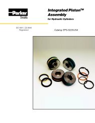
E. WINDOWSECTC <strong>Windows</strong>U.S. Customary[SI Metric]ELECTRICALLY CONDUCTIVE TRANSPARENT COATINGGENERAL DESCRIPTIONECTC WINDOWS are custom designed opticaldisplay panels produced by depositing a very thinelectrically conductive transparent coating directlyonto the surface of various optical substrate materialsto provide high EMI shielding performancecoupled with good light transmission properties.APPLICATION INFORMATIONApplications of ECTC WINDOWS are found inequipment requiring visual displays where theviewing panel must also serve to reduce the radiatedelectromagnetic energy entering or leavingthe device.SUBSTRATE MATERIALSMost transparent plastic and glass sheet materialare suitable for ECTC coating. However, eventhose optical substrate materials with high qualitysurfaces, have minute surface imperfectionswhich become more apparent after coating. Inmost applications these blemishes will notdegrade the appearance of the finished windowor the shielding performance.CONDUCTIVE COATINGStandard ECTC coating has a nominal resistivityof 14.0 ohms per square and a light transmissionof about 70 percent in the visible spectrum.Applying ECTC coatings to both surfaces of theoptical substrate, increases shielding effectivenessby 6 to 10 dB, while reducing the opticaltransmission from 70 percent to about 50 percent.ECTC coatings are easily damaged by abrasionsince “finger printing” from oils present in normalskin moisture are difficult to remove. In normalusage, the coating is applied to the inner surfaceof the window substrate which permits cleaning ofthe front surface with a commercial windowcleaner. NOTE: Inspection, handling and installationpersonnel should use clean, lint-free cottongloves when handling ECTC <strong>Windows</strong>.SPECIFICATIONSMATERIAL DESCRIPTION• Optical SubstrateAcrylic: Acrylic sheet per Federal SpecificationL-P-391, Type 1, Grade C, clear (ASTM-D-4802).Glass: Glass sheet per SpecificationASTM-C-1036, clear.Commercial Grade Polycarbonate• Conductive Coating:TECKNIT ECTC vacuum deposited thin metal film.Indium Tin Oxide coatings available upon request.• Busbar Termination: TECKNIT Silver Acrylic conductivecoating.• Mounting Frame (when specified): Aluminum alloyPERFORMANCE CHARACTERISTICS• CoatingSurface Resistivity: 14 ohms/square nominal(±4 ohms/square).• Temperature RangeAcrylic: -67°F to 150°F [-55°C to 65°C].Glass: -67°F to 167°F [-55°C to 85°C].MATERIAL H-FIELD E-FIELD PLANE WAVEECTC 100 kHz 10 MHz 1 GHz20 dB 90 dB 30 dBTested in accordance with TECKNIT Test MethodTSETS-01, which is based upon modified MIL-STD- 285. Typical values are based on a 5"square window.E-19U.S.A.: 908-272-5500 • U.K.: 44-1476-590600 • Spain: 34-91-4810178
E. WINDOWSBUSBAR TERMINATION ANDINTERFACE GASKETINGThe edges of ECTC WINDOWS are terminatedwith a border of highly conductive, silver busbarmaterial. This conductive band serves two purposes:1. Provides a uniform current distribution. Thebusbar material has a very low surface resistivitywhen compared to the ECTC coating.2. Provides a more durable low impedance bearingsurface than the ECTC coating alone. Aninterface gasket joins the ECTC window coating tothe enclosure panel.The most widely used interface gasket is TECK-NIT CONSIL, silver-filled silicone rubber gaskets.These gaskets provide both environmental andelectromagnetic sealing without damage to thebusbar or coating.FRAMING AND MOUNTINGStandard ECTC <strong>Windows</strong> can be mounted directlyto the equipment panel or enclosure without aninterface gasket using TECKNIT conductiveepoxy. When using standard interface gasketing,TECKNIT standard framing is available.STANDARD OPTICAL SUBSTRATE MATERIALTable 1. STANDARD THICKNESS (T)MATERIALS THICKNESS (T) TOLERANCEin. [mm] in. [mm]Acrylic .062 [1.52] ±.016 [0.41].125 [3.18] ±.020 [0.51]Glass .090 [2.29] ±.020 [0.51].125 [3.18] ±.020 [0.51]STANDARD WINDOW CONFIGURATIONFigure 1. Window Dimensioning.*Continuous Busbar around periphery(TECKNIT Silver Acrylic Conductive Coating).STANDARD FRAME STYLESFigure 2. Frame Cross SectionSTANDARD FRAME DIMENSIONINGFigure 3. Overall Frame StyleSTANDARD TOLERANCESTable 2.WINDOWSYMBOL DIMENSION TOLERANCEA,B 18 in. [up to 457 mm] ±.031 [0.79]FRAMEC,D,E,F,G 12 in. [up to 305 mm] ±.015 [0.38]12-18 in. [305 to 457 mm] ±.020 [0.50]K,L 12 in. [up to 102 mm] ±.015 [0.38]4-24 in. [102.1 to 610 mm] ±.031 [0.79]FRAME CROSS SECTIONW,X 0-.750 in. [up to 19 mm] ±.010 [0.25].750 -1.250 in. [19.1 to 31.8 mm] ±.012 [0.30]S,T .750 in. [up to 19 mm] ±.006 [0.15]ORDERING INFORMATIONECTC <strong>Windows</strong> are custom designed to customerspecifications and drawings. Customer drawingsshould provide dimensional data as suggested inFigure 3 such as overall size, viewing area, windowsize and thickness (dimensions AxB), type ofedge termination and interface gasket, type frameby style number and special options. For assistance,contact your TECKNIT representative orfactory engineer.Mexico: 528-18-369-8610 • China: 86-10-67884650 • www.tecknit.comE-20
E. WINDOWSTeckfilm TRANSPARENT CONDUCTIVE COATING ON POLYESTER FILMU.S. Customary[SI Metric]GENERAL DESCRIPTIONTECKFILM is a highly conductive coating depositedon a transparent polyester film. It is availablein rolls 30" wide. Usable width is 28". The conductivecoating is overcoated with a ceramic typefilm which serves to increase visible light transmissionand to provide a protective barrier thatexhibits electrical conductivity through the layer.CONSIL ® -II silver filled silicone elastomer materialis recommended between the TECKFILM andconductive mating surface as an interface gasketand an environmental seal between the enclosureand TECKFILM window panel assembly.APPLICATION INFORMATIONTECKFILM is designed for electric and planewaveshielding, grounding and static discharge applications.TECKFILM is used as a transparent, shieldingpanel for visual displays in instrumentationequipment, control panels, computer processing,printers, peripheral equipment and large electrodedisplays as a grounding shield.MOUNTING TECHNIQUESVarious methods of mounting are as follows:1. Affixed to conductive mating surface withclamps or bonded with TECKNIT Two-Part RTVSilver Silicone Adhesive Sealant (Part No. 72-00036).2. Mounted between a substrate and conductivemounting surface with or without the aid of edgebonding to the substrate.NOTE: TECKFILM conductive surface can bemarred if handled excessively.EMI SHIELDING PERFORMANCETECKNIT TECKFILM Shielding Effectiveness hasbeen tested in accordane with TECKNIT TestMethod TSETS-01 which is based upon modifiedMIL-STD- 285. Typical shielding effectiveness valuesare based on a 5" square window.SPECIFICATIONSMATERIAL DESCRIPTION• Substrate: Polyester film .005 in. [0.13mm] thick, clear and colorless.• Conductive Coating: Vacuum deposited thin metal film withprotective ceramic coating.• Standard Bulk MaterialPart Number: 70-00117PERFORMANCE CHARACTERISTICS• Substrate and CoatingSurface Resistivity: 14 ohms/square (nominal)(±4 ohms/square).Visible Light Transmission: 70 to 80%.Temperature Range: -76°F to 300°F [-60°C to 150°C].ORDERING INFORMATIONFabricated and rule die cut window shapes upto 28" wide can be supplied. Contact yourTECKNIT area representative or factory engineerfor assistance.MATERIAL H-FIELD E-FIELD PLANE WAVE100 kHz 10 MHz 1 GHzTECKFILM 20 dB 90 dB 30 dBE-21U.S.A.: 908-272-5500 • U.K.: 44-1476-590600 • Spain: 34-91-4810178
E. WINDOWSTeckshield ® -FHIGH PERFORMANCE EMC WINDOWSGENERAL DESCRIPTIONTECKSHIELD-F high-performance fully laminatedflat windows are specially designed to provideoptimum optical transmission and EMI shieldingin severe interference environments. TECK-SHIELD-F windows have proven to be effective inTEMPEST qualified Visual Display Units, as wellas in printers and enclosures requiring large viewingapertures. A special low-resistance mesh islaminated between two layers of glass or acrylic.The edge termination between the window meshand the enclosure is designed to provide uniformmesh-to-enclosure continuity around the entireperimeter of the shielding aperture.FEATURES• Full lamination provides rugged construction,prevents moisture intrusion or entrapmentbetween optical layers, enhances optical contrastby elimination of two optical media-to- airinterfaces.• High shielding performance of large viewingapertures at a broad range of frequencies.• Minimum optical distortion of viewed display.• Design options include color filters and polarizersfor contrast enhancement, which permitflexibility in matching optical and shieldingrequirements to specific applications.APPLICATION INFORMATIONTECKSHIELD-F high-performance flat windowsare designed for enclosures requiring superiorshielding against EMI radiation or susceptibility.They provide maximum EMI protection and highoptical clarity for teleprinters, digital, graphic, andother flat displays. TECKSHIELD-F windows canalso be economically matched to most visual displayunits to minimize image distortion and tomaximize shielding effectiveness.EMI SHIELDING PERFORMANCEMESH H-FIELD E-FIELD PLANE WAVESCREEN 100 KHZ 10 MHZ 1 GHZ 10 GHZ100 OPI 55 dB 120 dB 60 dB 40 dB145 OPI 55 dB 120 dB 80 dB 45 dBSPECIFICATIONSMATERIAL DESCRIPTION• Standard Optical MediaGlass: Per Specification ASTM-C-1036, Type 1, Class 1.Acrylic: Per Federal Specification L-P-391, Type 1, Grade C(ASTM-D-4802).• Optical Media OptionsAcrylic Colors: See Table 2.Anti-Reflection Coatings:Non-Glare Coating (Matte Finish).High Efficiency Anti-Reflection Coating(Less than 0.6% Reflection).• Mesh Screen100 OPI: Blackened Copper Mesh 0.0022" Wire Diameter,60% Open Area.145 OPI: Blackened Copper Mesh 0.0022" Wire Diameter,45% Open Area.Interface Gasket: Copper Mesh Wrap-Around Termination.See Figure 2.Duogasket: See Figure 3.Busbar Termination: Tecknit Silver Acrylic ConductiveCoating (Fig. 5)PERFORMANCE CHARACTERISTICS• Operating & Storage TemperatureGlass: -67°F to 176°F [-55°C to 80°C]Acrylic: -67°F to 140°F [-55°C to 60°C]Tested in accordance with TECKNIT Test MethodTSETS-01, which is based upon modified MIL-STD-285. Typical Shielding Effectiveness valuesare based on a 5" square window.Mexico: 528-18-369-8610 • China: 86-10-67884650 • www.tecknit.comE-22
E. WINDOWSU.S. Customary[SI Metric]STANDARD WINDOW CONSTRUCTIONStandard TECKSHIELD-F fully laminated windowconstruction consists of: (a) Standard meshscreen, blackened and laminated between (b)two layers of standard optical medium (clear andcolorless see Fig. 1), and with (c) an interfacialgasket (copper mesh wrap around or Duogasket)to provide electrical continuity between the windowmesh and equipment enclosure. TheDuogasket consists of an environmental sealand an EMI gasket seal.Standard window thicknesses are 0.205 in.[5.2 mm] for glass substrates and 0.145 in.[3.68 mm] for acrylic substrates.using TECKNIT conductive epoxy to establishan electrical bond to the enclosure. Additionalmechanical clips may be required to locate andmechanically secure the window to the enclosure.STANDARD TOLERANCES Table 1.WINDOWSYMBOL DIMENSION TOLERANCEA,B 18 in. [up to 457 mm] ±0.031 [0.79]FRAME DIMENSIONC,D,E,F,G up to 12 in. [305 mm]12 to 18 in. [305-457 mm]±0.015 [0.38]±0.020 [0.50]K,L up to 4 in. [102 mm]4 to 24 in. [102.1-610 mm]±0.015 [0.38]±0.031 [0.79]FRAME CROSS SECTIONW,X up to 0 - .750 in. [19 mm].750 to1.250 in. [19.1-31.8 mm]±0.010 [0.25]±0.012 [0.30]S,T up to 0.750 in. [19 mm] ±0.006 [0.15]E-23FRAMING AND MOUNTINGStandard TECKSHIELD-F windows may bemounted directly to the equipment enclosure utilizingthe recommended interface gasket terminationshown in Figs. 2, 3, 4 and 5. When specifyinga finished mounting frame for the standardwindow thickness shown in Fig. 1, provide adrawing of the frame as shown in Fig. 6 using theTECKNIT styles shown in Fig. 2-5.In some instances, standard TECKSHIELD-F windowsmay be mounted directly to the equipmentenclosure without an interface Duogasket byACRYLIC COLOR TRANSMISSION FILTERSTable 2.Red Amber Yellow Green Blue Gray2423 2422 2208 2092 2069 2514ORDERING INFORMATIONTECKSHIELD-F high-performance windows arecustom designed to customer specifications.Drawings should be provided that show dimensionaldata such as overall dimensions, mountinghole dimensions, desired viewing area, windowand frame thickness (when required), type ofedge terminations and interface gasket, type offrame or bezel and special options. For assistancecontact your nearest TECKNIT area representativeor factory location.Teckshield ® -F Polycarbonate <strong>Windows</strong>FEATURES• 80% open area-best light transmission of allTecknit woven window meshes.• Available as thin as .053" [1.35].• -60°F to 158°F [-55°C to 70°C] operatingtemperature.• All standard Tecknit EMI terminations available.EMI SHIELDING PERFORMANCEH-FIELD E-FIELD PLANE WAVE100 kHz 10 MHz 1 GHz 10 GHz80 OPI SS 35 dB 85dB 42 dB 30 dB100 OPI SS 40 dB 105 dB 52 dB 35 dBSPECIFICATIONSMATERIAL DESCRIPTION• Mesh Screen: Blackened 304 stainless steel, .001" dia.,80 or 100 openings per inch.• Standard Substrate: Polycarbonate, clear & colorless.• Available Upon RequestUL-94VO-rated polycarbonateAbrasion resistant & anti-glare coatingsU.S.A.: 908-272-5500 • U.K.: 44-1476-590600 • Spain: 34-91-4810178
E. WINDOWSTeckshield® -FAllycarbonate <strong>Windows</strong>ALLYCARBONATE EMI SHIELDED WINDOWSPHYSICAL & OPTICAL PROPERTIES OFMONOMER CASTING MEDIUMTemperature Range:-60ºCto 100ºC-60ºC to 130ºC (1 Hour Duration)Rockwell Hardness (M):97 ASTM Test Method (D 785)Visible Transmission %:93.3 ASTM Test Method (D1003)Tecknit Allylcarbonate shielded windows are manufacturedby casting a woven EMI shield meshinto a material that has optical properties similarto that of glass. The window offers a lightweight,cost effective alternative to traditional glass laminatedshielded windows and is a more flexiblematerial to machine, making it more suited tomeet the changing design demands that are partof modern electronics.Available Standard Shielding Mesh Types50 OPI - Blackened stainless steel woven screen 0.001inch diameter wire100 OPI - Blackened stainless steel woven screen 0.001inch diameter wire100 OPI - Blackened copper woven screen 0.002 inchdiameter wireShielding Performance of Mesh ScreensH-FIELD E-FIELD PLANE WAVE100 kHz 10 MHz 1 GHz 10 GHz50 OPI 16db 45db 56db 36db100 OPI 40db 105db 52db 35db100 OPI 55db 120db 60db 40dbNote: (OPI Number of openings per inch of woven screen)Some examples of shielding screens also available as a non-standard are,80 OPI and 150 OPI woven materials, however lead times for these productsmay vary. Please contact our Sales Office.Allylcarbonace windows are ideally suited toapplications where there is a requirement toshield displays or visual apertures. <strong>Windows</strong> aremachined using computerised programmingtechnology This offers a facility to accuratelyengrave data or drill mounting holes into the windowitself.The windows operate in a very broad temperaturerange and have a high resistance to abrasion andmost acids and solvents. The window product isideally suited to many applications and is nowsupplied throughout a broad range of companiesin military and Commercial Industries.FEATURES• 80% open area-best light transmission of allTecknit woven window meshes.• Available as thin as .053" [1.35].• -60°F to 158°F [-55°C to 70°C] operatingtemperature.• All standard Tecknit EMI terminations available.• Cast Material Supplied as a Standard.079” [2mm] to .236” [6mm] thickClear or medium-grade matte finishMexico: 528-18-369-8610 • China: 86-10-67884650 • www.tecknit.comE-24