Integrated Lights Out Manager (ILOM) Administration Guide
Integrated Lights Out Manager (ILOM) Administration Guide
Integrated Lights Out Manager (ILOM) Administration Guide

You also want an ePaper? Increase the reach of your titles
YUMPU automatically turns print PDFs into web optimized ePapers that Google loves.
<strong>Integrated</strong> <strong>Lights</strong> <strong>Out</strong> <strong>Manager</strong>(<strong>ILOM</strong>) <strong>Administration</strong> <strong>Guide</strong>For <strong>ILOM</strong> 1.0Sun Microsystems, Inc.www.sun.comPart No. 819-1160-13October 2006, Revision 01Submit comments about this document at: http://www.sun.com/hwdocs/feedback
ContentsPrefacexi1. <strong>ILOM</strong> and System Management Overview 1–11.1 Introduction 1–11.1.1 Common Tasks That You Can Perform With <strong>ILOM</strong> 1–21.1.2 <strong>ILOM</strong> Default Settings 1–31.2 About Sun N1TM System <strong>Manager</strong> 1–42. <strong>ILOM</strong> Initial Setup 2–12.1 Connecting to the <strong>ILOM</strong> Using a Serial Connection 2–12.2 Connecting to the <strong>ILOM</strong> Using an Ethernet Connection 2–32.2.1 Configure the IP Address Using BIOS Setup Utility 2–42.2.2 Configuring the <strong>ILOM</strong> to use DHCP 2–52.2.3 Configuring the <strong>ILOM</strong> to Use a Static IP Address 2–62.2.3.1 Obtain the <strong>ILOM</strong> IP Address 2–62.2.3.2 Configuring a Static IP Address Using CLI and a SerialConnection 2–72.2.3.3 Configuring a Static IP Address Using CLI andEthernet 2–82.2.3.4 Configuring a Static IP Address Using the WebGUI 2–83. Using the Command Line Interface 3–1iii
3.1 Logging In To and <strong>Out</strong> Of CLI 3–13.2 Using CLI Commands 3–33.2.1 CLI Namespace 3–33.2.2 Privilege Levels 3–43.2.3 CLI Command Syntax 3–43.2.3.1 Command Verbs 3–53.2.3.2 Command Options 3–53.2.3.3 Command Targets 3–63.2.3.4 Command Properties 3–63.3 Managing Access to <strong>ILOM</strong> 3–63.3.1 Displaying Access Settings 3–73.3.2 Configuring Access Settings 3–73.3.2.1 Syntax 3–73.3.2.2 Targets, Properties, and Values 3–73.3.2.3 Examples 3–83.4 Managing the Host 3–83.4.1 Managing the Host State 3–93.4.2 Managing the Host Console 3–93.4.3 Viewing Host Sensors 3–93.5 Managing <strong>ILOM</strong> Network Settings 3–103.5.1 Displaying Network Settings 3–103.5.2 Configuring Network Settings 3–103.5.2.1 Syntax 3–113.5.2.2 Targets, Properties, and Values 3–113.6 Managing <strong>ILOM</strong> Serial Port Settings 3–123.6.1 Displaying Serial Port Settings 3–123.6.2 Configuring Serial Port Settings 3–123.6.2.1 Syntax 3–12iv <strong>Integrated</strong> <strong>Lights</strong> <strong>Out</strong> <strong>Manager</strong> (<strong>ILOM</strong>) <strong>Administration</strong> <strong>Guide</strong> • October 2006
3.6.2.2 Targets, Properties, and Values 3–133.7 Managing User Accounts 3–133.7.1 Adding a User Account 3–143.7.2 Deleting a User Account 3–143.7.3 Displaying User Accounts 3–143.7.4 Configuring User Accounts 3–143.7.4.1 Syntax 3–153.7.4.2 Targets, Properties, and Values 3–153.8 Managing <strong>ILOM</strong> Alerts 3–153.8.1 Displaying Alerts 3–163.8.2 Configuring Alerts 3–163.8.2.1 Syntax 3–163.8.2.2 Targets, Properties, and Values 3–173.9 Managing Clock Settings 3–183.9.1 Displaying Clock Settings 3–183.9.2 Configuring the Clock to Use NTP Servers 3–183.9.2.1 Syntax 3–183.9.2.2 Targets, Properties, and Values 3–183.10 Displaying <strong>ILOM</strong> Information 3–193.10.1 Displaying Version Information 3–193.10.2 Displaying Available Targets 3–193.11 Updating the <strong>ILOM</strong> Firmware 3–204. Using the WebGUI 4–14.1 Overview of WebGUI Requirements, Users, Tasks and Features 4–14.1.1 Browser and Software Requirements 4–24.1.2 Users and Privileges 4–24.1.3 WebGUI Tasks 4–24.1.4 WebGUI Features 4–3Contentsv
4.2 Logging In and <strong>Out</strong> of the WebGUI 4–45. System Monitoring and Maintenance Using the WebGUI 5–15.1 Upgrading the <strong>ILOM</strong> Firmware 5–25.2 Resetting the <strong>ILOM</strong> 5–55.3 Resetting the <strong>ILOM</strong> and BIOS Passwords 5–65.4 Viewing Replaceable Component Information 5–65.5 Viewing Temperature, Voltage, and Fan Sensor Readings 5–75.6 Viewing Alert Destinations and Configuring Alerts 5–115.6.1 Viewing Alert Destinations 5–115.6.2 Configuring an Alert 5–135.6.3 Sending a Test Alert 5–145.7 Viewing and Clearing the System Event Log 5–155.7.1 Interpreting the System Event Log (SEL) Time Stamps 5–175.8 Enabling SNMP Settings and Viewing SNMP Users 5–185.8.1 Configuring SNMP Settings 5–185.8.2 Adding, Editing and Deleting SNMP Communities 5–205.8.3 Adding, Modifying and Deleting SNMP Users 5–225.9 Controlling the Server Locator Indicator 5–235.10 Viewing <strong>ILOM</strong> Hardware, Firmware, and IPMI Versions 5–245.11 Viewing Active Connections to the <strong>ILOM</strong> 5–256. System Configuration Using the WebGUI 6–16.1 Setting the <strong>ILOM</strong> Session Time-<strong>Out</strong> Period 6–16.2 Configuring the <strong>ILOM</strong> Serial Port 6–26.3 Setting the <strong>ILOM</strong> Clock 6–46.3.1 Setting the <strong>ILOM</strong> Clock Manually 6–46.3.2 Synchronizing the <strong>ILOM</strong> Clock with an NTP Server: 6–56.3.3 Interpreting <strong>ILOM</strong> Clock Settings 6–5vi <strong>Integrated</strong> <strong>Lights</strong> <strong>Out</strong> <strong>Manager</strong> (<strong>ILOM</strong>) <strong>Administration</strong> <strong>Guide</strong> • October 2006
6.4 Configuring Network Settings 6–66.5 Uploading a New SSL Certificate 6–86.6 Enabling HTTP or HTTPS Web Access 6–107. Managing Users Using the WebGUI 7–17.1 Managing User Accounts 7–17.1.1 Adding User Roles and Setting Privileges 7–27.1.2 Modifying an <strong>ILOM</strong> User Account 7–57.1.3 Deleting a User Account 7–77.2 Viewing and Modifying Lightweight Directory Access Protocol Settings7–88. Using The Remote Console Application 8–18.1 About the Remote Console Application 8–18.1.1 Installation Requirements 8–28.1.2 CD and Diskette Redirection Operational Model 8–38.2 Starting the Remote Console Application 8–48.3 Redirecting Keyboard, Video, Mouse, or Storage Devices 8–108.3.1 Redirecting Keyboard and Mouse Devices 8–108.3.2 Redirecting Storage Devices 8–128.4 Controlling Power to the Host Server 8–139. Using Intelligent Platform Management Interface (IPMI) 9–19.1 About IPMI 9–19.1.1 IPMItool 9–29.2 Supported IPMI 2.0 Commands 9–210. Lightweight Directory Access Protocol (LDAP) 10–110.0.1 How LDAP Servers Organize Directories 10–110.0.2 How LDAP Clients and Servers Work 10–310.1 Configuring LDAP 10–4Contentsvii
10.1.1 Configuring LDAP Server 10–410.1.2 Configure <strong>ILOM</strong> 10–510.1.2.1 Using the CLI 10–510.1.2.2 Using the WebGUI 10–611. Using Simple Network Management Protocol (SNMP) 11–111.1 About SNMP 11–111.1.1 How SNMP Works 11–111.2 SNMP Management Information Base (MIB) Files 11–211.3 MIBs Integration 11–311.4 About SNMP Messages 11–311.5 About <strong>ILOM</strong> and SNMP 11–411.5.1 Integrating the MIBs 11–411.5.2 Adding Your Server to Your SNMP Environment 11–411.5.3 Configuring Receipt of SNMP Traps 11–411.6 Managing SNMP User Accounts 11–511.6.1 Adding a User Account 11–511.6.2 Deleting a User Account 11–511.6.3 Configuring User Accounts 11–511.6.3.1 Syntax 11–511.6.3.2 Targets, Properties, and Values 11–611.6.3.3 Examples 11–6A. Command Line Interface Reference A–1A.1 CLI Command Quick Reference A–1A.2 CLI Command Reference A–5A.2.1 Using the cd Command A–6A.2.2 Using the create Command A–6A.2.3 Using the delete Command A–7viii <strong>Integrated</strong> <strong>Lights</strong> <strong>Out</strong> <strong>Manager</strong> (<strong>ILOM</strong>) <strong>Administration</strong> <strong>Guide</strong> • October 2006
A.2.4 Using the exit Command A–8A.2.5 Using the help Command A–9A.2.6 Using the load Command A–10A.2.7 Using the reset Command A–11A.2.8 Using the set Command A–12A.2.9 Using the show Command A–14A.2.10 Using the start Command A–18A.2.11 Using the stop Command A–19A.2.12 Using the version Command A–19GlossaryGlossary–1IndexIndex–1Contentsix
x <strong>Integrated</strong> <strong>Lights</strong> <strong>Out</strong> <strong>Manager</strong> (<strong>ILOM</strong>) <strong>Administration</strong> <strong>Guide</strong> • October 2006
PrefaceThis <strong>Integrated</strong> <strong>Lights</strong> <strong>Out</strong> <strong>Manager</strong> (<strong>ILOM</strong>) <strong>Administration</strong> <strong>Guide</strong> provides instructionsfor managing Sun servers using the <strong>Integrated</strong> <strong>Lights</strong> <strong>Out</strong> <strong>Manager</strong> (<strong>ILOM</strong>).<strong>ILOM</strong> is included on certain Sun servers. If you have one of these servers, it willinclude an <strong>ILOM</strong> Supplement, which contains platform-specific information, such assensors and thresholds, and details about the hardware.Sun Welcomes Your CommentsSun is interested in improving its documentation and welcomes your comments andsuggestions. You can submit your comments by going to:http://www.sun.com/hwdocs/feedbackPlease include the title and part number of your document with your feedback:<strong>Integrated</strong> <strong>Lights</strong> <strong>Out</strong> <strong>Manager</strong> (<strong>ILOM</strong>) <strong>Administration</strong> <strong>Guide</strong>, part number 819-1160-13xi
Using UNIX CommandsThis document might not contain information about basic UNIX ® commands andprocedures such as shutting down the system, booting the system, and configuringdevices. Refer to the following for this information:■■Software documentation that you received with your systemSolaris Operating System documentation, which is at:http://docs.sun.comThird-Party Web SitesSun is not responsible for the availability of third-party web sites mentioned in thisdocument. Sun does not endorse and is not responsible or liable for any content,advertising, products, or other materials that are available on or through such sitesor resources. Sun will not be responsible or liable for any actual or alleged damageor loss caused by or in connection with the use of or reliance on any such content,goods, or services that are available on or through such sites or resources.Typographic ConventionsTypeface *AaBbCc123AaBbCc123AaBbCc123MeaningThe names of commands, files,and directories; onscreencomputer outputWhat you type, when contrastedwith onscreen computer outputBook titles, new words or terms,words to be emphasized.Replace command-line variableswith real names or values.ExamplesEdit your.login file.Use ls -a to list all files.% You have mail.% suPassword:Read Chapter 6 in the User’s <strong>Guide</strong>.These are called class options.You must be superuser to do this.To delete a file, type rm filename.* The settings on your browser might differ from these settings.xii <strong>Integrated</strong> <strong>Lights</strong> <strong>Out</strong> <strong>Manager</strong> (<strong>ILOM</strong>) <strong>Administration</strong> <strong>Guide</strong> • October 2006
CHAPTER 1<strong>ILOM</strong> and System ManagementOverviewThis chapter contains the following sections:■ Section 1.1, “Introduction” on page 1-1.■ Section 1.2, “About Sun N1TM System <strong>Manager</strong>” on page 1-4.1.1 IntroductionThe <strong>ILOM</strong> is a dedicated system of hardware and supporting software that allowsyou to manage your Sun server independently of the operating system.<strong>ILOM</strong> includes the following components:■ Service Processor (SP) - This is the hardware. It consists of a dedicated processorboard that communicates through the system serial port and a dedicated Ethernetport.■ Command Line Interface (CLI) - The command line interface is a dedicatedsoftware application that allows you to operate the <strong>ILOM</strong> using keyboardcommands. You can use the command-line interface to send commands to the<strong>ILOM</strong>. You can connect a terminal or emulator directly to the system serial port,or connect over the Ethernet using a Secure Shell (SSH).To log in to and use the CLI, see Chapter 3.■WebGUI - The WebGUI provides a powerful, yet easy-to-use browser interfacethat allows you to log in to the SP and perform system management, monitoring,and IPMI tasks.For instructions on how to use the WebGUI, see Chapter 4.1-1
■Remote Console/Java Client - The Java Client supports the Remote Consolefunctionality, which allows you to access your server’s console remotely. Itredirects the keyboard, mouse, and video screen, and can redirect input andoutput from the local machine’s CD and diskette drives.For instructions on how to use the remote console, see Chapter 8.You do not need to install additional hardware or software to begin managing yourserver with <strong>ILOM</strong>.<strong>ILOM</strong> also supports industry-standard IPMI and SNMP management interfaces:■ Intelligent Platform Management Interface (IPMI) v2.0 – Using a Secure Shell(SSH), you can interact with the <strong>ILOM</strong> to do the following: establish secureremote control of your server, monitor the status of hardware componentsremotely, monitor system logs, receive reports from replaceable components, andredirect the server console.For more on IPMI, see Chapter 9.■Simple Network Management Protocol (SNMP) interface – <strong>ILOM</strong> also provides anSNMP v3.0 interface (with limited support for SNMP v1 and SNMP v2c) forexternal data center management applications such as Sun N1 System <strong>Manager</strong>,IBM Tivoli, and Hewlett-Packard OpenView.For more on SNMP, see Chapter 11.Which interface you use depends on your overall system management plan and thespecific tasks that you wish to perform.1.1.1 Common Tasks That You Can Perform With <strong>ILOM</strong>TABLE 1-1 shows common tasks and the management interfaces used to perform eachtask.TABLE 1-1Common TasksTaskRedirect the system graphical console to a remoteclient browser.Connect a remote diskette drive to the system as avirtual diskette drive.Connect a remote CD-ROM drive to the system as avirtual CD-ROM drive.IPMIWebInterface CLI SNMPYesYesYesMonitor system fans, temperatures, and voltagesremotely.Yes Yes Yes Yes1-2 <strong>Integrated</strong> <strong>Lights</strong> <strong>Out</strong> <strong>Manager</strong> (<strong>ILOM</strong>) <strong>Administration</strong> <strong>Guide</strong> • October 2006
TABLE 1-1Common Tasks (Continued)TaskIPMIWebInterface CLI SNMPMonitor system BIOS messages remotely. Yes Yes YesMonitor system operating system messages remotely. Yes Yes YesInterrogate system components for their IDs and/orserial numbers.Yes Yes YesRedirect the system serial console to a remote client. No Yes YesMonitor system status (health check) remotely. Yes Yes Yes YesInterrogate system network interface cards remotelyfor MAC addresses.Yes Yes YesManage user accounts remotely. Yes Yes YesManage system power status remotely (power on,power off, power reset).Monitor and manage environmental settings for keysystem components (CPUs, motherboards, fans).Yes Yes YesYes Yes Yes Monitoronly1.1.2 <strong>ILOM</strong> Default SettingsSun has configured the <strong>ILOM</strong> card and <strong>ILOM</strong> firmware on your server to reflect themost common default settings used in the field. It is unlikely that you will need tochange any of these defaults, which appear in TABLE 1-2.TABLE 1-2<strong>ILOM</strong> Default SettingsSystem Component Default Status Action RequiredService Processor card Preinstalled NoneService Processor firmware Preinstalled NoneIPMI interface Enabled NoneWebGUI Enabled NoneCommand-line interface (CLI) Enabled NoneSNMP interface Enabled NoneChapter 1 <strong>ILOM</strong> and System Management Overview 1-3
1.2 About Sun N1 TM System <strong>Manager</strong>If you plan to manage your server as one resource in a comprehensive data centermanagement solution, Sun N1 System Management provides an alternative to<strong>ILOM</strong>. This software suite provides advanced virtualization features that enable youto monitor, maintain, and provision multiple Solaris, Linux, and Microsoft Windowsservers in your data center.The Sun N1 System <strong>Manager</strong> is available to download from:www.sun.com/software/solaris/index.jspYou can also install it from the Sun N1 System <strong>Manager</strong> DVD shipped in yoursystem box. This software suite is installed on a dedicated server in your data centerand allows one or more remote management clients to perform the following taskson multiple managed servers:■ Manage multiple servers – Configure, provision, deploy, manage, monitor, patch,and update from one to thousands of Sun servers.■ Monitor system information – System manufacturer, make, model, serial number,management MAC addresses, disk information, expansion slot information, andplatform CPU and memory information.■ Manage power remotely – Power off, power on, power reset, and power status.■ Manage <strong>ILOM</strong>s and BIOS – Information about system <strong>ILOM</strong> firmware, version,and status. You can also perform remote upgrades to firmware on <strong>ILOM</strong>s.■ Manage system boot commands and options – Remote boot control via IPMI andremote mapping of boot devices and boot options.■ Manage remote system health checks – Information about the status of a server.■ Manage operating systems – Deploy, monitor, and patch both Solaris and Linuxoperating systems.■ Perform bare-metal discovery.To learn more about this suite of powerful data center management tools, see:http://www.sun.com/software/products/system_manager/1-4 <strong>Integrated</strong> <strong>Lights</strong> <strong>Out</strong> <strong>Manager</strong> (<strong>ILOM</strong>) <strong>Administration</strong> <strong>Guide</strong> • October 2006
CHAPTER 2<strong>ILOM</strong> Initial SetupThis chapter describes how to do the <strong>ILOM</strong> initial setup.The <strong>ILOM</strong> communicates through the system serial port and/or through a dedicatedEthernet port.■ You can run the Command Line Interface (CLI) connected directly to the serialport.■ You can run the CLI and the WebGUI through the Ethernet port.Connecting with the Ethernet requires some configuration.This chapter contains the following sections:■ Section 2.1, “Connecting to the <strong>ILOM</strong> Using a Serial Connection” on page 2-1.■ Section 2.2, “Connecting to the <strong>ILOM</strong> Using an Ethernet Connection” on page 2-3.2.1 Connecting to the <strong>ILOM</strong> Using a SerialConnectionYou can access the <strong>ILOM</strong> CLI at any time by connecting a terminal or a PC runningterminal emulation software to the RJ-45 serial port on the <strong>ILOM</strong> board.1. Verify that your terminal, laptop, or terminal server is operational.2. Configure that terminal device or the terminal emulation software to use thefollowing settings:■ 8N1: eight data bits, no parity, one stop bit■ 9600 baud■ Disable hardware flow control (CTS/RTS)2-1
3. Unpack your server and connect the system power cable to a power source.Refer to your platform-specific documentation for instructions on installing thehardware, cabling, and powering on.4. Connect a serial cable from the serial port on the server’s back panel to a terminaldevice.Refer to your -specific documentation or the supplement for the location of the serialport.Note – The serial port requires that the serial cable connected to it use the followingpin assignments. Note that these are the same as the serial cable connector for theSun Advanced <strong>Lights</strong> <strong>Out</strong> <strong>Manager</strong> (ALOM) or Remote System Control (RSC). SeeTABLE 2-1.TABLE 2-1PinSerial Management Port PinoutsSignal Description1 Request To Send (RTS)2 Data Terminal Ready (DTR)3 Transmit Data (TXD)4 Ground5 Ground6 Receive Data (RXD)7 Data Carrier Detect (DCD)8 Clear To Send (CTS)5. Press Enter on the terminal device.This establishes the connection between the terminal device and the <strong>ILOM</strong>.Note – If you connect a terminal or emulator to the serial port before it has beenpowered up or during its power up sequence, you will see bootup messages.When the system has booted, the <strong>ILOM</strong> displays its login prompt:SUNSPnnnnnnnnnn login:The first string in the prompt is the default host name. It consists of the prefixSUNSP and the <strong>ILOM</strong>’s MAC address. The MAC address for each <strong>ILOM</strong> is unique.2-2 <strong>Integrated</strong> <strong>Lights</strong> <strong>Out</strong> <strong>Manager</strong> (<strong>ILOM</strong>) <strong>Administration</strong> <strong>Guide</strong> • October 2006
6. Log in to the CLI:a. Type the default user name, root.b. Type the default password, changeme.Once you have successfully logged in, the <strong>ILOM</strong> displays the <strong>ILOM</strong> defaultcommand prompt:->The <strong>ILOM</strong> is now accessing the CLI. You can now run CLI commands.For example, to display status information about the motherboard in your server,type the following command:-> show /SYS/MB7. To go to the host serial console (host COM0), type the following commands:cd /SP/consolestartNote – After you have returned to the serial console, to switch back to the CLI,enter the Escape-( key sequence.Chapter 3 describes how to use the CLI.For instructions on how to use the serial console, see the platform-specificdocumentation.2.2 Connecting to the <strong>ILOM</strong> Using anEthernet ConnectionTo access the full range of <strong>ILOM</strong> functionality, you must connect a LAN to theEthernet port and configure your Ethernet connection.<strong>ILOM</strong> supports Dynamic Host Configuration Protocol (DHCP) and static IPaddressing.■ To configure DHCP or a static IP address using the BIOS, see Section 2.2.1,“Configure the IP Address Using BIOS Setup Utility” on page 2-4■ To configure DHCP, see Section 2.2.2, “Configuring the <strong>ILOM</strong> to use DHCP” onpage 2-5.Chapter 2 <strong>ILOM</strong> Initial Setup 2-3
■To configure a static IP address, see Section 2.2.3, “Configuring the <strong>ILOM</strong> to Use aStatic IP Address” on page 2-6.2.2.1 Configure the IP Address Using BIOS SetupUtilityThe BIOS Setup Utility allows you to set the <strong>ILOM</strong> IP address. It allows you toconfigure it manually, or use DHCP.1. Unpack your server and connect the system power cable to a power source.Refer to your platform documentation for instructions on installing the hardware,cabling, and powering on.2. If you are going to use DHCP, verify that your DHCP server is configured toaccept new media access control (MAC) addresses.3. Start the BIOS Setup Utility.a. Boot the system.b. Watch the boot messages. You will see a line that says you can press F2 to enterBIOS setup.c. After you see the message, press F2.After some messages and screen changes, the BIOS Setup Utility appears.4. Select the Advanced tab.The Advanced page appears.5. Highlight IPMI 2.0 Configuration in the list, then select Enter.The IPMI 2.0 Configuration page appears.6. Fill in the IPMI 2.0 Configuration page.a. Under IP Assignment, select DHCP or Static.b. If you selected Static, fill in the IP address, subnet mask and default gateway atthe bottom of the page.7. Select Commit to save your changes.If you selected DHCP, the BIOS utility automatically updates the address fields.Caution – You must use Commit to save the changes on this page. Using F10 willnot save your changes.2-4 <strong>Integrated</strong> <strong>Lights</strong> <strong>Out</strong> <strong>Manager</strong> (<strong>ILOM</strong>) <strong>Administration</strong> <strong>Guide</strong> • October 2006
2.2.2 Configuring the <strong>ILOM</strong> to use DHCPTo configure the <strong>ILOM</strong> to use a DHCP address:1. Verify that your DHCP server is configured to accept new media access control(MAC) addresses.2. Unpack your server and connect the system power cable to a power source.Refer to your platform documentation for instructions on installing the hardware,cabling, and powering on.3. Obtain the <strong>ILOM</strong> MAC address from one of the following locations.MAC addresses are 12-digit hexadecimal strings in the format xx:xx:xx:xx:xx:xxwhere x represents a single hexadecimal letter (0–9, A–F, a–f). Write down thataddress for future reference.■ The <strong>ILOM</strong> has a serial port to which you can attach a terminal device. If you login to the <strong>ILOM</strong> and enter the command show /SP/network, the <strong>ILOM</strong> displaysthe current Mac address.■ The label attached to the GRASP board. You need to open the cover of the serverto view this label.■ The Customer Information Sheet shipped with your server.■ The system BIOS setup screen. Choose Advanced - IPMI 2.0 Configuration - SetLAN Configuration - MAC address.■ Command-line interface. Log in to the <strong>ILOM</strong> via the CLI and type the commandshow /SP/network to display the MAC address.4. Connect an Ethernet cable to the RJ-45 NET MGT Ethernet port.Refer to your platform documentation or the supplement for the location of RJ-45NET MGT Ethernet port.5. You can assign an Ethernet address directly, or you can let DHCP assign one foryou.a. To assign your own Ethernet address, use the DHCP configuration software toassign an IP address to the MAC address noted above. See the DHCP serverdocumentation for details.b. To let DHCP assign an IP address:Note – Different DHCP server applications running on different operating systemsstore these log files in different locations. Consult your DHCP system administratorto locate the correct path to the log file.i. When you connect an Ethernet cable to the <strong>ILOM</strong>, the <strong>ILOM</strong> provides itsMAC address and DHCP assigns the <strong>ILOM</strong> an IP address.Chapter 2 <strong>ILOM</strong> Initial Setup 2-5
ii. Log in to your DHCP server and view its DHCP log file.iii. Identify the IP address in the log file that corresponds to the <strong>ILOM</strong> MACaddress.Typically, DHCP log file entries are individual lines with the following commaseparatedfields:ID, Date, Time, Description, IP Address, Host Name, MAC AddressLocate the MAC address of your <strong>ILOM</strong> in the MAC Address (seventh) field ofthe correct DHCP file entry, and record the corresponding value of the IPAddress (fifth) field. This is the IP address that you must use to access theWebGUI and the remote console.When this procedure is complete, you can access the <strong>ILOM</strong> using the IP addressassigned by DHCP.2.2.3 Configuring the <strong>ILOM</strong> to Use a Static IP AddressUsually, you will configure the <strong>ILOM</strong> to use DHCP, as described in Section 2.2.2,“Configuring the <strong>ILOM</strong> to use DHCP” on page 2-5.If you choose to configure the <strong>ILOM</strong> using a static IP address, you can do so usingthree different methods:■ CLI serial connection (Section 2.2.3.2, “Configuring a Static IP Address Using CLIand a Serial Connection” on page 2-7)■ CLI Ethernet connection (Section 2.2.3.3, “Configuring a Static IP Address UsingCLI and Ethernet” on page 2-8)■ WebGUI Ethernet (Section 2.2.3.4, “Configuring a Static IP Address Using theWebGUI” on page 2-8)■ BIOS Setup Utility (Section Section 2.2.1, “Configure the IP Address Using BIOSSetup Utility” on page 2-4)2.2.3.1 Obtain the <strong>ILOM</strong> IP AddressBefore you begin, you must obtain the <strong>ILOM</strong> IP address from one of the followinglocations. Record the IP address for future reference.2-6 <strong>Integrated</strong> <strong>Lights</strong> <strong>Out</strong> <strong>Manager</strong> (<strong>ILOM</strong>) <strong>Administration</strong> <strong>Guide</strong> • October 2006
■■Command-line interface. Log in to the <strong>ILOM</strong> via the CLI and type the commandshow /SP/network to display the IP address.The system BIOS setup screen. Choose Advanced => IPMI 2.0 Configuration.Under LAN Configuration, look at IP Address.Note – You can set the IP address using the BIOS Setup Utility.If the address on the IPMI configuration page is acceptable, you do not need tochange anything.To change the IP address, type the new address in the IP address field. Type in a newsubnet mask and default gateway if necessary. When you are done, click Commit.See Section 2.2.1, “Configure the IP Address Using BIOS Setup Utility” on page 2-4for details.2.2.3.2 Configuring a Static IP Address Using CLI and a SerialConnectionTo set a static IP address for the <strong>ILOM</strong> using the CLI and a serial line connection, dothe following.1. Establish a serial connection to the <strong>ILOM</strong>.See Section 2.1, “Connecting to the <strong>ILOM</strong> Using a Serial Connection” on page 2-1 fordetails.2. Log in to the <strong>ILOM</strong>.3. Type the following command to set the working directory.cd /SP/network4. Type the following commands to specify a static Ethernet configuration.set pendingipaddress=xxx.xxx.xx.xxset pendingipnetmask=yyy.yyy.yyy.yset pendingipgateway=zzz.zzz.zz.zzzset commitpending=truewhere xxx.xxx.xx.xx, yyy.yyy.yyy.y and zzz.zzz.zz.zzz are the IP address, netmask, andgateway for your <strong>ILOM</strong> and network configuration. To obtain the <strong>ILOM</strong> IP address,see Section 2.2.3.1, “Obtain the <strong>ILOM</strong> IP Address” on page 2-6.5. Log out of the <strong>ILOM</strong>.Chapter 2 <strong>ILOM</strong> Initial Setup 2-7
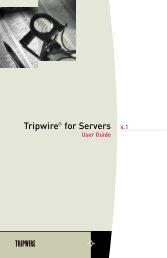
2.2.3.3 Configuring a Static IP Address Using CLI and Ethernet1. Log in to the <strong>ILOM</strong> using Secure Shell (SSH) over the network, or by connectinga terminal to the serial port.To establish a Secure Shell (SSH) connection to the CLI, type the appropriateconnection command in the SSH application. For example, to connect to the <strong>ILOM</strong>with an IP address of 129.144.82.20, type the following command:# ssh -l root 129.144.82.20Use the IP address you obtained in Section 2.2.3.1, “Obtain the <strong>ILOM</strong> IP Address” onpage 2-6.2. Type the following command to set the working directory.cd /SP/network3. Type the following commands to specify a static Ethernet configuration.Note – The following values are samples only. You must specify the IP address,netmask, and gateway appropriate for your <strong>ILOM</strong> and network configuration.set pendingipaddress=129.144.82.26set pendingipnetmask=255.255.255.0set pendingipgateway=129.144.82.254set pendingipdiscovery=staticset commitpending=true2.2.3.4 Configuring a Static IP Address Using the WebGUITo set a static IP address for the <strong>ILOM</strong> using the WebGUI, do the following.1. Connect to the <strong>ILOM</strong> through a web browser running on a remote system.Use the IP address you obtained in Section 2.2.3.1, “Obtain the <strong>ILOM</strong> IP Address” onpage 2-6.2. Log in to the WebGUIThe default user name is root, and the default password is changeme.3. Choose the Configuration tab and its Network tab to display information aboutthe current <strong>ILOM</strong> network configuration. See FIGURE 2-1.4. Select the Use the Following IP Address option. See FIGURE 2-1.2-8 <strong>Integrated</strong> <strong>Lights</strong> <strong>Out</strong> <strong>Manager</strong> (<strong>ILOM</strong>) <strong>Administration</strong> <strong>Guide</strong> • October 2006
FIGURE 2-1<strong>Integrated</strong> <strong>Lights</strong> <strong>Out</strong> <strong>Manager</strong> Network Settings Page5. Modify the displayed settings as required and click save.Chapter 2 <strong>ILOM</strong> Initial Setup 2-9
2-10 <strong>Integrated</strong> <strong>Lights</strong> <strong>Out</strong> <strong>Manager</strong> (<strong>ILOM</strong>) <strong>Administration</strong> <strong>Guide</strong> • October 2006
CHAPTER 3Using the Command Line InterfaceThis chapter describes how to use the <strong>ILOM</strong>’s Command Line Interface (CLI). Thesections include:■ Section 3.1, “Logging In To and <strong>Out</strong> Of CLI” on page 3-1.■ Section 3.2, “Using CLI Commands” on page 3-3.■ Section 3.3, “Managing Access to <strong>ILOM</strong>” on page 3-6.■ Section 3.4, “Managing the Host” on page 3-8.■ Section 3.5, “Managing <strong>ILOM</strong> Network Settings” on page 3-10.■ Section 3.6, “Managing <strong>ILOM</strong> Serial Port Settings” on page 3-12.■ Section 3.7, “Managing User Accounts” on page 3-13.■ Section 3.8, “Managing <strong>ILOM</strong> Alerts” on page 3-15.■ Section 3.9, “Managing Clock Settings” on page 3-18.■ Section 3.10, “Displaying <strong>ILOM</strong> Information” on page 3-19..■ Section 3.11, “Updating the <strong>ILOM</strong> Firmware” on page 3-20.3.1 Logging In To and <strong>Out</strong> Of CLIYou can access the command line through the serial port or over the Ethernet.■■Serial port – The serial port provides access to the CLI and to the system console.IPMI terminal mode and PPP mode are not available on the serial port.SSH –You can connect to the CLI using an Ethernet connection. Secure shellconnections (SSC) are enabled by default.The <strong>ILOM</strong> supports a maximum of 10 active sessions, including serial, SSH, and webinterface sessions. You can view active sessions by entering the command show/SP/sessions.3-1
Note – Telnet connections to the <strong>ILOM</strong> are not supported.Logging In and <strong>Out</strong> Using SSH1. Start your SSH client2. To log in to the <strong>ILOM</strong>, type:$ ssh root@SPipaddress3. Type your password when prompted.Note – The default user name is root, and the default password is changeme.For example:$ ssh root@192.168.25.25root@192.168.25.25's password:Sun <strong>Integrated</strong> <strong>Lights</strong> <strong>Out</strong> <strong>Manager</strong>Version 1.0Copyright 2006 Sun Microsystems, Inc. All rights reserved.Warning: password is set to factory default.->4. To log out, type exit.Logging In and <strong>Out</strong> Using the Serial Port1. Configure your terminal device or the terminal emulation software running on alaptop or PC to the following settings:■ 8N1: eight data bits, no parity, one stop bit■ 9600 baud■ Disabled software flow control (CTS/RTS)2. Connect a serial cable from the <strong>ILOM</strong> RJ-45 Serial Mgt port to a terminal device.3. Press ENTER on the terminal device to establish a connection between thatterminal device and the <strong>ILOM</strong>.You should see the following prompt:SUNSP0003BA84D777 login:3-2 <strong>Integrated</strong> <strong>Lights</strong> <strong>Out</strong> <strong>Manager</strong> (<strong>ILOM</strong>) <strong>Administration</strong> <strong>Guide</strong> • October 2006
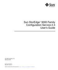
4. Log in to the <strong>ILOM</strong> and type the user name and password.The default user name is root, and the default password is changeme.Note – Once you have logged in to the <strong>ILOM</strong> as root, change the default passwordfor increased security.5. To log out, type exit.3.2 Using CLI CommandsThis section describes how to use CLI commands.3.2.1 CLI NamespaceThe CLI architecture is based on a hierarchical namespace, which is a predefined treethat contains every managed object in the system. This namespace defines thetargets for each command verb.The <strong>ILOM</strong> includes two namespaces: the /SP namespace, and the /SYS namespace.■ The /SP namespace manages the <strong>ILOM</strong>. For example, you use this space tomanage users, clock settings, and other <strong>ILOM</strong> issues. FIGURE 3-1 shows the /SPnamespace.■ The /SYS namespace manages the host system. For example, you can change thehost state, read sensor information, and access other information for managedsystem hardware. Your /SYS namespace diagram is determined by the managedhardware devices in your server.Chapter 3 Using the Command Line Interface 3-3
You can view your /SYS namespace by typing the show /SYS command from thecommand line. FIGURE 3-1 shows the /SP namespace. The /SYS namespace is uniqueto each platform.FIGURE 3-1SP Namespace3.2.2 Privilege LevelsThe CLI provides two privilege levels: Administrator and Operator. Administratorshave full access to <strong>ILOM</strong> functionality and Operators have read-only access to <strong>ILOM</strong>information.Note – The default user, root, has administrator privileges. To create a user accountwith operator privileges, see Section 3.7.1, “Adding a User Account” on page 3-14.CLI commands are case-sensitive.3.2.3 CLI Command SyntaxThe syntax of a command is: The following sections describe each of these.3-4 <strong>Integrated</strong> <strong>Lights</strong> <strong>Out</strong> <strong>Manager</strong> (<strong>ILOM</strong>) <strong>Administration</strong> <strong>Guide</strong> • October 2006
3.2.3.1 Command VerbsThe CLI supports the following command verbs.TABLE 3-1CommandcdcreatedeleteexithelploadresetsetshowstartstopversionCLI Command VerbsDescriptionNavigates the object namespace.Sets up an object in the namespace.Removes an object from the namespace.Terminates a session to the CLI.Displays Help information about commands and targets.Transfers a file from an indicated source to an indicated target.Resets the state of the target.Sets target properties to the specified value.Displays information about targets and properties.Starts the target.Stops the target.Displays the version of <strong>ILOM</strong> firmware running.3.2.3.2 Command OptionsThe CLI supports the following options. All options are not supported for allcommands. See a specific command section for the options that are valid with thatcommand. The help and examine options can be used with any command.TABLE 3-2Command OptionsOption Long Form Short Form Description-default-destinationCauses the verb to perform only its default functions.Specifies the destination for data.-display -d Shows the data the user wants to display.-examine -x Examines the command but does not execute it.-force -f Causes an immediate action instead of an orderlyshutdown.-help -h Displays Help information.Chapter 3 Using the Command Line Interface 3-5
TABLE 3-2Command Options (Continued)Option Long Form Short Form Description-level -l Executes the command for the current target and alltargets contained through the level specified.-output -o Specifies the content and form of command output.-script-sourceSkips warnings or prompts normally associated withthe command.Indicates the location of a source image.3.2.3.3 Command TargetsEvery object in your namespace is a target. All targets are not supported for allcommands. Section A.2, “CLI Command Reference” on page A-5 lists eachcommand, with its targets and properties.3.2.3.4 Command PropertiesProperties are the configurable attributes specific to each object. An object can haveone or more properties. Section A.2, “CLI Command Reference” on page A-5 listseach command, with its targets and properties.3.3 Managing Access to <strong>ILOM</strong>You can display or configure HTTP, HTTPS, and Secure Shell (SSH) services from theCLI. By default, HTTPS access is enabled.<strong>ILOM</strong> is managed through the /SP namespace.3-6 <strong>Integrated</strong> <strong>Lights</strong> <strong>Out</strong> <strong>Manager</strong> (<strong>ILOM</strong>) <strong>Administration</strong> <strong>Guide</strong> • October 2006
3.3.1 Displaying Access SettingsTABLE 3-3 shows the commands used to display access settings.TABLE 3-3Commands to Display Access SettingsType this command...show /SP/services/httpshow /SP/services/httpsshow /SP/services/ssh/keys/dsashow /SP/services/ssh/keys/rsato display this setting.HTTPHTTPSSSH key3.3.2 Configuring Access SettingsUse the set command to change properties and values for HTTP and HTTPSservices.3.3.2.1 Syntaxset target [propertyname=value]3.3.2.2 Targets, Properties, and ValuesTABLE 3-3 shows the valid targets, properties, and values for HTTP, HTTPS, and SSHservices.TABLE 3-4Valid Targets, Properties and Values for HTTP, HTTPS and SSHTarget Property Value Default/SP/services/httpport80secureredirectenabled|disabledenabledservicestateenabled|disableddisabledChapter 3 Using the Command Line Interface 3-7
TABLE 3-4Valid Targets, Properties and Values for HTTP, HTTPS and SSHTarget Property Value Default/SP/services/httpsport443servicestateenabled|disabledenabled/SP/services/ssh/keys/dsafingerprintlengthpublickey/SP/services/ssh/keys/rsafingerprintlengthpublickey3.3.2.3 ExamplesTo configure automatic redirection from HTTP to HTTPS, type:set /SP/services/http secureredirect=trueTo change the HTTPS port to 445 type:set /SP/services/https port=4453.4 Managing the HostYou can use the <strong>ILOM</strong> to change the host's state and to access the host console.3-8 <strong>Integrated</strong> <strong>Lights</strong> <strong>Out</strong> <strong>Manager</strong> (<strong>ILOM</strong>) <strong>Administration</strong> <strong>Guide</strong> • October 2006
3.4.1 Managing the Host StateTo send a break to the host, type:Escape + B (press the Escape key and type upper case B).To power on the host, type:start /SYSTo power off the host, type:stop /SYSTo reset the host, type:reset /SYSNote – Entering reset /SYS does not affect the power state of the host.3.4.2 Managing the Host ConsoleType the following command to start a session to the server console:start /SP/consoleType the following command to terminate a server console session started byanother user:stop /SP/console3.4.3 Viewing Host SensorsHost systems are equipped with sensors that show the state of critical components.For example, they record things like temperatures, voltages and fan speeds. Theshow command can be used to show the state of sensors. Use the command:show /SYS/sensorChapter 3 Using the Command Line Interface 3-9
where sensor is a particular sensor. For example, the following command shows thestate of sensor /PROC/P0:-> show /SYS/PROC/P0/SYS/PROC/P0Targets:Properties:T_CORE = 7700.000000 RPMV_+1V25 = 1.404000 VoltsV_+1V5 = 45.000000 degrees CV_+2V5 = 7800.000000 RPMCommands:cdshowFor more information about sensors, including how to view them using the WebGUI,see Section 5.5, “Viewing Temperature, Voltage, and Fan Sensor Readings” onpage 5-7For details on individual sensors, see your platform supplement.3.5 Managing <strong>ILOM</strong> Network SettingsYou can display or configure the <strong>ILOM</strong> network settings from the CLI.3.5.1 Displaying Network SettingsType the following command to display network settings:show /SP/network3.5.2 Configuring Network SettingsUse the set command to change properties and values for network settings.Network settings have two sets of properties: pending and active. The active settingsare the settings currently in use by the <strong>ILOM</strong>. These settings are read-only. If youwant to change settings, enter the updated settings as the pending settings3-10 <strong>Integrated</strong> <strong>Lights</strong> <strong>Out</strong> <strong>Manager</strong> (<strong>ILOM</strong>) <strong>Administration</strong> <strong>Guide</strong> • October 2006
(pendingipaddress or pendingipgateway), then set the commitpendingproperty to true. This prevents accidental disconnections for both port and networksettings.Note – Ensure that the same IP address is always assigned to an <strong>ILOM</strong> by eitherassigning a static IP address to your <strong>ILOM</strong> after initial setup, or configuring yourDHCP server to always assign the same IP address to an <strong>ILOM</strong>. This enables the<strong>ILOM</strong> to be easily located on the network.3.5.2.1 Syntaxset target [propertyname=value]3.5.2.2 Targets, Properties, and ValuesThe following targets, properties, and values are valid for <strong>ILOM</strong> network settings.TABLE 3-5<strong>ILOM</strong> Network Targets, Properties and ValuesTarget Property Value Default/SP/networkcommitpendingtrue|(none)(none)pendingipaddressnonependingipdiscoverydhcp|staticdhcppendingipgatewaynonependingipnetmask255.255.255.255ExamplesTo change the IP address for the <strong>ILOM</strong>, type:-> set /SP/network ipaddress=nnn.nn.nn.nn commitpending=trueNote – Changing the IP address will disconnect your active session if you areconnected to the <strong>ILOM</strong> via a network.To change the network settings from DHCP to static assigned settings, type:-> set /SP/network pendingipdiscovery=static pendingipaddress=nnn.nn.nn.nn pendingipgateway=nnn.nn.nn.nn pendingipnetmask=nnn.nn.nn.nn commitpending=trueChapter 3 Using the Command Line Interface 3-11
3.6 Managing <strong>ILOM</strong> Serial Port SettingsYou can display or configure the <strong>ILOM</strong> serial port settings from the CLI. The <strong>ILOM</strong>has two serial ports: an internal host port that interfaces directly with the host serverusing the start /SP/console command, and an external port that is exposed onback of the server.3.6.1 Displaying Serial Port SettingsType the following command to display settings for the external serial port:show /SP/serial/externalType the following command to display settings for the host serial port:show /SP/serial/host3.6.2 Configuring Serial Port SettingsUse the set command to change properties and values for serial port settings. Portsettings have two sets of properties: pending and active. The active settings are thesettings currently in use by the <strong>ILOM</strong>. These settings are read-only. If you want tochange settings, enter the updated settings as the pending settings, then set thecommitpending property to true. This prevents accidental disconnections for bothport and network settings.3.6.2.1 Syntaxset target [propertyname=value]3-12 <strong>Integrated</strong> <strong>Lights</strong> <strong>Out</strong> <strong>Manager</strong> (<strong>ILOM</strong>) <strong>Administration</strong> <strong>Guide</strong> • October 2006
3.6.2.2 Targets, Properties, and ValuesThe following targets, properties, and values are valid for <strong>ILOM</strong> serial ports.TABLE 3-6Valid Targets, Properties and Values for <strong>ILOM</strong> Serial PortsTarget Property Value Default/SP/serial/externalcommitpendingtrue|(none)(none)flowcontrolnonenonependingspeed9600speed96009600/SP/serial/hostcommitpendingtrue|(none)(none)pendingspeed(none)speed96009600ExampleTo change the speed (baud rate) for the host serial port from 9600 to 57600, type:-> set /SP/serial/host pendingspeed=56000 commitpending=trueNote – The speed of the host serial port must match the speed setting for serial port0, COM1, or /dev/ttys0 on the host operating system for the <strong>ILOM</strong> tocommunicate properly with the host.3.7 Managing User AccountsThis section explains how to add, modify and delete <strong>ILOM</strong> user accounts.The <strong>ILOM</strong> supports up to 10 user accounts, Two of those, root and anonymous, areset by default and cannot be removed. Therefore, you can configure eight additionalaccounts.Each user account consists of a user name, a password, and a role.Caution – The <strong>ILOM</strong> includes a user account "sunservices," which shares the <strong>ILOM</strong>root password. Normally, it is used exclusively by Sun Service personnel; however itcan also be used to perform recovery procedures documented in the product notes.Incorrect use of this account can corrupt the service processor image or operations.Chapter 3 Using the Command Line Interface 3-13
The roles include:■■Administrator - Enables access to all <strong>ILOM</strong> features, functions, and commands.Operator - Enables limited access to <strong>ILOM</strong> features, functions, and commands. Ingeneral, Operators cannot changed configuration settings.Operators cannot:■ See or change LDAP settings■ Add or remove users■ Change network settings (view only)■ Change Network Time Protocol (NTP) settings (view only)■ Change SNMP settings (view only)■ Change HTTP settings (view only)3.7.1 Adding a User AccountType the following command to add a local user account:create /SP/users/username password=password role=administrator|operator3.7.2 Deleting a User AccountType the following command to delete a local user account:delete /SP/users/username3.7.3 Displaying User AccountsType the following command to display information about all local user accounts:show /SP/users3.7.4 Configuring User AccountsUse the set command to change passwords and roles for configured user accounts.3-14 <strong>Integrated</strong> <strong>Lights</strong> <strong>Out</strong> <strong>Manager</strong> (<strong>ILOM</strong>) <strong>Administration</strong> <strong>Guide</strong> • October 2006
3.7.4.1 Syntaxset target [propertyname=value]3.7.4.2 Targets, Properties, and ValuesThe following targets, properties, and values are valid for local user accounts.TABLE 3-7Valid Targets, Properties and Values for Local User AccountsTarget Property Value Default/SP/users/usernamepermissionsadministrator|operatoroperatorpasswordExamplesWhen changing the role for user1 from Administrator to Operator type:-> set /SP/users/user1 role=operatorTo change user1's password type:-> set /SP/users/user1 passwordChanging password for user /SP/users/user1/password...Enter new password:********Enter new password again:********New password was successfully set for user /SP/users/user1Note – You must have Administrator privileges to change user properties.3.8 Managing <strong>ILOM</strong> AlertsThe system is equipped with a number of sensors that measure voltages,temperatures and other things. <strong>ILOM</strong> polls the sensors and posts an event in theevent log (SEL) when they cross a threshold. Some of these readings are also used toperform actions such as adjusting fan speeds, illuminating LEDs and powering offthe chassis.Chapter 3 Using the Command Line Interface 3-15
The alert management view allows you to configure the system to send alerts to IPaddresses.Caution – The <strong>ILOM</strong> tags all events or actions with LocalTime=GMT (or UDT).Browser clients show these events in LocalTime. This can cause apparentdiscrepancies in the event log. When an event occurs on the <strong>ILOM</strong>, the event logshows it in UDT, but a client would show it local time.An alert is an IPMI Platform Event Trap (PET) generated when a sensor crosses thespecified threshold. For example, if you configure an alert for critical thresholds, the<strong>ILOM</strong> sends an IPMI trap to the specified destination when any sensor crosses theupper or lower critical (CT) threshold.All alerts are IPMI PET traps, as defined in the Intelligent Platform ManagementInterface (IPMI) v2.0.A special criteria, informational, is reserved for system events that are not related tosensors.3.8.1 Displaying AlertsType the following command to display alerts:show /SP/alert/rules3.8.2 Configuring AlertsUse the set command to change properties and values for alerts.3.8.2.1 Syntaxset target [propertyname=value]3-16 <strong>Integrated</strong> <strong>Lights</strong> <strong>Out</strong> <strong>Manager</strong> (<strong>ILOM</strong>) <strong>Administration</strong> <strong>Guide</strong> • October 2006
3.8.2.2 Targets, Properties, and ValuesThe following targets, properties, and values are valid for IPMI PET alerts.TABLE 3-8Valid Targets, Properties and Values for IPMI Pet AlertsTarget Property Value Default/SP/alert/rules/1...15 destinationleveldisable|information|warning|critical|non-recoverable(none)disableThe parameters are:■ rule – The number of the alert rule; a number from 1 to 15.■ipaddress – The IP address to which the alert will be sent.■ level – The severity level of the alert (see TABLE 3-9).TABLE 3-9Alert LevelsAlert LevelsName in SensorReadings ViewDescriptionInformational N/A This level traps system events that are not relatedto sensors, such as “The host has booted.”warning NC The sensor is outside of its normal range but notcritical.critical CT The sensor has crossed a critical threshold.non-recoverable NR The sensor has reached a threshold beyond thetolerance level of the corresponding component(s).disable N/A Don’t send alerts at this level.ExamplesTo configure an alert, type:-> set /SP/alert/rules/1 destination=128.145.77.21 level=criticalTo change an alert level to critical, type:-> set /SP/alert/rules/1 level=criticalTo turn off an alert, type:-> set /SP/alert/rules/1 level=disableChapter 3 Using the Command Line Interface 3-17
3.9 Managing Clock SettingsYou can display clock settings or configure your clock to synchronize with one ortwo Network Time Protocol (NTP) servers. If you do not configure an NTP server,the time is set by the system BIOS.3.9.1 Displaying Clock SettingsType the following command to display clock settings:show /SP/clock3.9.2 Configuring the Clock to Use NTP ServersUse the set command to change properties and values for NTP servers.3.9.2.1 Syntaxset target [propertyname=value]3.9.2.2 Targets, Properties, and ValuesThe following targets, properties, and values are valid for NTP servers.TABLE 3-10Valid Targets, Properties and Values for NTP ServersTarget Property Value Default/SP/clients/ntp/server/1 address (none)/SP/clients/ntp/server/2 address (none)ExampleTo configure your clock to synchronize with an NTP server, type:-> set /SP/clients/ntp/server/1 address=125.128.84.20Then enable the NTP service by typing:3-18 <strong>Integrated</strong> <strong>Lights</strong> <strong>Out</strong> <strong>Manager</strong> (<strong>ILOM</strong>) <strong>Administration</strong> <strong>Guide</strong> • October 2006
-> set /SP/clock/usentpserver=enabledNote – Once you enable the NTP service, it can take up to five minutes for the clockto synchronize.3.10 Displaying <strong>ILOM</strong> InformationYou can display active session, current versions, and other information about the<strong>ILOM</strong> using the CLI. TABLE 3-11 shows the commands and the information theydisplay.TABLE 3-11CommandCommands To Display <strong>ILOM</strong> InformationDisplays...versionshow /SP/cli/commandsshow /SP/sessionshelp targetsThe current <strong>ILOM</strong> versionAll of the CLI commandsAll active sessionsAvailable valid targets3.10.1 Displaying Version InformationType the following command to display the current <strong>ILOM</strong> version:3.10.2 Displaying Available TargetsType the following command to display the available valid targets:help targetsChapter 3 Using the Command Line Interface 3-19
3.11 Updating the <strong>ILOM</strong> FirmwareYou can use CLI to update the <strong>ILOM</strong> firmware. Updating the <strong>ILOM</strong> from thecommand line enables you to update both the <strong>ILOM</strong> firmware and the BIOS at thesame time. See Section A.2.6, “Using the load Command” on page A-10 for moreinformation.Caution – Ensure that you have reliable power before upgrading your firmware. Ifpower to the system fails (for example, if the wall socket power fails or the system isunplugged) during the firmware update procedure, the <strong>ILOM</strong> could be left in anunbootable state.Caution – Shut down your host operating system before proceeding. Otherwise the<strong>ILOM</strong> will shut the host down ungracefully, which could cause file systemcorruption.Note – The upgrade takes about five minutes to complete. During this time, noother tasks can be performed in the <strong>ILOM</strong>.1. If the server OS is running, perform a clean shutdown.2. Type the following command to update the <strong>ILOM</strong> firmware:load -source URLNote – A network failure during the file upload will result in a time-out. Thiscauses the <strong>ILOM</strong> to reboot with the prior version of the <strong>ILOM</strong> firmware.3-20 <strong>Integrated</strong> <strong>Lights</strong> <strong>Out</strong> <strong>Manager</strong> (<strong>ILOM</strong>) <strong>Administration</strong> <strong>Guide</strong> • October 2006
Example:-> load -source tftp://archive/newmainimageAre you sure you want to load the specified file (y/n)? yFile upload is complete.Firmware image verification is complete.Do you want to preserve the configuration (y/n)? nUpdating firmware in flash RAM:.Firmware update is complete.<strong>ILOM</strong> will not be restarted with the new firmware.Chapter 3 Using the Command Line Interface 3-21
3-22 <strong>Integrated</strong> <strong>Lights</strong> <strong>Out</strong> <strong>Manager</strong> (<strong>ILOM</strong>) <strong>Administration</strong> <strong>Guide</strong> • October 2006
CHAPTER 4Using the WebGUIThis chapter describes how to use the <strong>ILOM</strong> WebGUI.The sections include:■ Section 4.1, “Overview of WebGUI Requirements, Users, Tasks and Features” onpage 4-1.■ Section 4.1.4, “WebGUI Features” on page 4-3■ Section 4.2, “Logging In and <strong>Out</strong> of the WebGUI” on page 4-44.1 Overview of WebGUI Requirements,Users, Tasks and FeaturesThe graphical user interface (GUI) enables you to monitor and manage local andremote systems. Using a standard Internet browser, you can expect to be up andrunning the WebGUI in less than five minutes.One of the most powerful features of <strong>ILOM</strong> is the ability to redirect the server'sgraphical console to a remote workstation or laptop system. When you redirect thehost console, you can configure the remote system's keyboard and mouse to act asthe server's mouse and keyboard. You can also configure the diskette drive or CD-ROM drive on the remote system as a device virtually connected to the Sun server.You can also redirect diskette images (.img) and CD-ROM images (.iso) for remoteaccess.4-1
4.1.1 Browser and Software RequirementsThe WebGUI has been tested successfully with recently released Mozilla, Firefox,and Internet Explorer web browsers, and may be compatible with other webbrowsers.The <strong>ILOM</strong> product comes preinstalled on the Sun server. However, you need Javasoftware on the client to perform redirection, as described in Chapter 8.4.1.2 Users and PrivilegesAfter you log in to the WebGUI, you can perform basic software provisioning,Intelligent Platform Management Interface (IPMI) tasks, and system monitoring.<strong>ILOM</strong> user accounts include a role which defines what you can do. The roles are:■ Administrator - Enables access to all <strong>ILOM</strong> features, functions, and commands.■ Operator - Enables limited access to <strong>ILOM</strong> features, functions, and commands.Operators cannot changed their assigned roles or privileges.For more information on users, including how to manage user accounts using theWebGUI, see Chapter 7.4.1.3 WebGUI TasksSome of the common tasks you can perform using the WebGUI include:■■■■■■■■■■Redirect the system's graphical console to a remote client browser.Connect a remote diskette drive or diskette image to the system as a virtualdiskette drive.Connect a remote CD-ROM drive or CD-ROM image to the system as a virtualCD-ROM drive.Monitor system fans, temperatures, and voltages remotely.Monitor BIOS power-on self-test (POST) progress log entries remotely.View IPMI log entries, which the operating system can write.Examine component information, including CPU information, dynamic randomaccessmemory (DRAM) configuration, host Media Access Control (MAC)addresses, system serial numbers, and other features.Manage user accounts remotely.Power on, power off, power cycle, and reset the system remotely.Administer user accounts.4-2 <strong>Integrated</strong> <strong>Lights</strong> <strong>Out</strong> <strong>Manager</strong> (<strong>ILOM</strong>) <strong>Administration</strong> <strong>Guide</strong> • October 2006
4.1.4 WebGUI FeaturesA WebGUI page is shown below.MastheadNavigation BarContentFIGURE 4-1WebGUI SampleEach WebGUI page has three main sections: the masthead, the navigation bar, andthe content area.The masthead provides the following buttons and fields on all pages of the WebGUI:■ Refresh button – Click to refresh the information in the content area of the page.The Refresh button does not save new data that you may have entered or selectedon the page. Use the Save button that is provided in the content area for a specificWebGUI page.Note – Do not use the Refresh button from your Internet web browser when you areusing the WebGUI.■■■■Log <strong>Out</strong> button – Click to end the current session of the WebGUI. You are directedto the logout screen.About button – Click to view copyright information.User field – Displays the user name of the current user of the WebGUI.Server field – Displays the name of the <strong>ILOM</strong>.The navigation bar provides tabs that you can click to open a specific WebGUI page.When you click a main tab, subcategories of tabs are displayed, providing you withfurther options to choose. Select the tabs to open the appropriate WebGUI pages.Chapter 4 Using the WebGUI 4-3
The content area of the WebGUI page is where you find information about thespecific topic or operation you chose using the tabs. The content area displays suchthings as logs, status indicators, task wizards, and command buttons to execute anoperation.4.2 Logging In and <strong>Out</strong> of the WebGUIThis section explains how to log in to and out of the WebGUI.Note – The <strong>ILOM</strong> boots automatically when the Sun server is cabled appropriatelyand plugged in to an AC supply, usually within one minute. However, if themanagement Ethernet is not connected or if the <strong>ILOM</strong>'s Dynamic HostConfiguration Protocol (DHCP) process fails due to the absence of a DHCP server onthe management network, the <strong>ILOM</strong> might take a few minutes to boot.Disabling the use of the browser proxy server (if one is used) for access to themanagement network might make the WebGUI response time faster.Note – Do not use the Refresh or Log <strong>Out</strong> buttons in your Internet web browserwhen using the WebGUI. Instead, only use the Refresh and Log <strong>Out</strong> buttonsprovided at the top right of the WebGUI window.You need the IP address of the <strong>ILOM</strong>. The <strong>ILOM</strong>'s IP address is provided in the BIOSSetup screen. You can also observe the DHCP server issue the IP address when the<strong>ILOM</strong> boots, or look up the <strong>ILOM</strong>'s MAC address-to-IP address mapping in theDHCP server's logs or lease file.1. To log in to the WebGUI, type the IP address of the <strong>ILOM</strong> into your web browser.The login screen appears.4-4 <strong>Integrated</strong> <strong>Lights</strong> <strong>Out</strong> <strong>Manager</strong> (<strong>ILOM</strong>) <strong>Administration</strong> <strong>Guide</strong> • October 2006
FIGURE 4-2WebGUI Login Screen2. Type your user name and password.When you first try to access the WebGUI, it prompts you to type the default username and password. The default user name and password are:■ Default user name – root■Default password – changemeThe default user name and password are in lowercase characters.One local user ID is predefined with the user name root with the role Administrator.You cannot delete this user ID or change its role attributes. The initial passwordchangeme also is provided. This password is required for log in on the serial port,Secure Shell (SSH), and the WebGUI. To increase secure access to the <strong>ILOM</strong>, changethe default password to a new, unique password. See Section 5.4, “ViewingReplaceable Component Information” on page 5-6.3. Click Log In.The WebGUI appears.Chapter 4 Using the WebGUI 4-5
● To log out of the WebGUI, click the Log <strong>Out</strong> button at the top right of theWebGUI.The log out screen appears.Do not use the Log <strong>Out</strong> button in your web browser to log out from the WebGUI.FIGURE 4-3WebGUI Log <strong>Out</strong> Screen4-6 <strong>Integrated</strong> <strong>Lights</strong> <strong>Out</strong> <strong>Manager</strong> (<strong>ILOM</strong>) <strong>Administration</strong> <strong>Guide</strong> • October 2006
CHAPTER 5System Monitoring andMaintenance Using the WebGUIThis chapter describes how to use the WebGUI to perform monitoring andmaintenance.It includes the following sections:■ Section 5.1, “Upgrading the <strong>ILOM</strong> Firmware” on page 5-2.■ Section 5.2, “Resetting the <strong>ILOM</strong>” on page 5-5.■ Section 5.3, “Resetting the <strong>ILOM</strong> and BIOS Passwords” on page 5-6.■ Section 5.4, “Viewing Replaceable Component Information” on page 5-6.■Section 5.5, “Viewing Temperature, Voltage, and Fan Sensor Readings” onpage 5-7.■ Section 5.6, “Viewing Alert Destinations and Configuring Alerts” on page 5-11.■ Section 5.7, “Viewing and Clearing the System Event Log” on page 5-15.■ Section 5.8, “Enabling SNMP Settings and Viewing SNMP Users” on page 5-18.■ Section 5.9, “Controlling the Server Locator Indicator” on page 5-23.■ Section 5.10, “Viewing <strong>ILOM</strong> Hardware, Firmware, and IPMI Versions” onpage 5-24■ Section 5.11, “Viewing Active Connections to the <strong>ILOM</strong>” on page 5-255-1
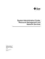
5.1 Upgrading the <strong>ILOM</strong> FirmwareBoth the <strong>ILOM</strong> and BIOS firmware are tightly coupled and are always updatedtogether. A single firmware image contains both the <strong>ILOM</strong> and BIOS firmware.Caution – Ensure that you have reliable power before upgrading your firmware. Ifpower to the system fails (for example, if the wall socket power fails or the system isunplugged) during the firmware update procedure, the <strong>ILOM</strong> could be left in anunbootable state.Do not proceed until you have reliable power.Caution – Shut down your host operating system before proceeding. Otherwise the<strong>ILOM</strong> will shut the host down ungracefully, which could cause file systemcorruption.Note – The upgrade takes about five minutes to complete. During this time, noother tasks can be performed in the <strong>ILOM</strong>.To observe the status of the upgrade while it’s happening, set the session time-out to3 hours. See Section 6.1, “Setting the <strong>ILOM</strong> Session Time-<strong>Out</strong> Period” on page 6-1 fordetails.1. Log in to the <strong>ILOM</strong> with administrator privileges.2. Ensure that you can access the new flash image on the client machine that you areusing to update the <strong>ILOM</strong>.3. If the server OS is running, perform a clean shutdown.4. From the Maintenance tab, choose Firmware Upgrade.The Upgrade the Firmware page appears.Caution – Do not close the WebGUI using the Log <strong>Out</strong> button in the web browserwhen the <strong>ILOM</strong> is in Upgrade mode. If you must close the WebGUI, use theWebGUI’s Cancel button.5-2 <strong>Integrated</strong> <strong>Lights</strong> <strong>Out</strong> <strong>Manager</strong> (<strong>ILOM</strong>) <strong>Administration</strong> <strong>Guide</strong> • October 2006
FIGURE 5-1Upgrade Page5. Click Enter Upgrade Mode.A dialog box appears and asks you to confirm that you want to enter Upgrademode.6. Click OK to enter Upgrade mode.The <strong>ILOM</strong> stops its normal operation and prepares for a flash upgrade.7. Type the path to the new <strong>ILOM</strong> flash image file in the Select File to Upload field,or click the Browse button to locate and select the firmware update file (*.ima).FIGURE 5-2File Name DialogChapter 5 System Monitoring and Maintenance Using the WebGUI 5-3
8. Click Upload.The Upgrade wizard copies the selected file into the <strong>ILOM</strong>'s DRAM and thenverifies that the copy procedure was successful. This takes about one minute with afast network connection.The system displays a confirmation dialog box.Note – A network failure during the file upload will result in a time out and the<strong>ILOM</strong> will reboot with the prior version of the <strong>ILOM</strong> firmware.9. In the dialog box, click OK.The Verify Firmware Image dialog appears.FIGURE 5-3Verify Firmware Image Dialog10. Select Preserve Configuration to keep your <strong>ILOM</strong> settings. Otherwise, they willbe overwritten.■ Upgradable Modules – Select Service Processor Firmware to upgrade thefirmware image and BIOS.■ Preserve Configuration – Select this to retain your original configuration settings.Deselect it to overwrite them.11. Click the Start Upgrade button, or click the Cancel button to stop the upgrade.5-4 <strong>Integrated</strong> <strong>Lights</strong> <strong>Out</strong> <strong>Manager</strong> (<strong>ILOM</strong>) <strong>Administration</strong> <strong>Guide</strong> • October 2006
Note – If you choose to cancel the firmware upgrade operation, the <strong>ILOM</strong> willreboot without the updated software. You must close the Internet browser and logback in to the WebGUI before you can perform any other type of operation.If you clicked Start Update, a progress screen indicates that the firmware image isbeing upgraded. Once the upgrade progress reaches 100%, the firmware upgrade iscomplete.After the upgrade operation has completed successfully, the <strong>ILOM</strong> willautomatically reboot. This is done so that the image upgrade can take effect.Note – You cannot perform any other operation within your current Internetbrowser session.12. Close your Internet browser and reconnect to the <strong>ILOM</strong>.Note – If the configuration is not preserved, enter BIOS setup and save the optimaldefault settings.5.2 Resetting the <strong>ILOM</strong>1. Log in to the <strong>ILOM</strong> as Administrator or Operator to reach the WebGUI.2. From the Maintenance tab, choose Reset SP.Chapter 5 System Monitoring and Maintenance Using the WebGUI 5-5
The Reset Service Processor page appears.FIGURE 5-4Reset Service Processor Page3. Click the Reset SP button to reset the <strong>ILOM</strong>.The <strong>ILOM</strong> reboots. The WebGUI is unavailable while the <strong>ILOM</strong> reboots.5.3 Resetting the <strong>ILOM</strong> and BIOS PasswordsThis procedure causes the <strong>ILOM</strong> to reset the administration password and to clearthe BIOS password.■ The administration (root) password becomes changeme.■The BIOS password is cleared, so that when you attempt to access the BIOS, itdoes not prompt for a password.This procedure requires changing a hardware jumper in your server enclosure. Seeyour service manual for details.5.4 Viewing Replaceable ComponentInformationThis section explains how to view detailed information about the Sun serverreplaceable components, sometimes referred to as field-replaceable units (FRUs) andcustomer-replaceable units (CRUs).5-6 <strong>Integrated</strong> <strong>Lights</strong> <strong>Out</strong> <strong>Manager</strong> (<strong>ILOM</strong>) <strong>Administration</strong> <strong>Guide</strong> • October 2006
Depending on the component you select, information about the manufacturer,component name, serial number, and part number might be displayed.1. Log in to the <strong>ILOM</strong> as Administrator or Operator to reach the WebGUI.2. From the System Information tab, select Components.The Replaceable Component Information page appears.FIGURE 5-5Sample Replacable Component Page3. Select a component from the drop-down list.Information about the selected component appears.5.5 Viewing Temperature, Voltage, and FanSensor ReadingsThis section explains how to view the temperature, voltage, and fan sensor readings.For details on individual sensors, see your platform supplement.Chapter 5 System Monitoring and Maintenance Using the WebGUI 5-7
The system is equipped with a number of sensors that measure voltages,temperatures, and other settings. <strong>ILOM</strong> polls the sensors and posts an event in thesensor event log (SEL) when they cross a threshold. Some of these readings are alsoused to perform actions, such as adjusting fan speeds, illuminating LEDs andpowering off the chassis.If an event crosses a threshold defined in the Alert Destinations view, it generates analert, which is sent to the destination configured in Section 5.6, “Viewing AlertDestinations and Configuring Alerts” on page 5-11.The thresholds appear in the Sensor Readings view shown in FIGURE 5-6.Caution – The <strong>ILOM</strong> tags all events or actions with LocalTime=GMT (or UDT).Browser clients show these events in LocalTime. This can cause apparentdiscrepancies in the event log. When an event occurs on the <strong>ILOM</strong>, the event logshows it in UDT, but a client would show it local time.1. Log in to the <strong>ILOM</strong> as Administrator or Operator to reach the WebGUI.2. From the System Monitoring tab, choose Sensor Readings.Note – The sensor displays in this section are examples. The sensor names, rangesand functions might be different on your system. For details, see your platformsupplement.The Sensor Readings page appears.5-8 <strong>Integrated</strong> <strong>Lights</strong> <strong>Out</strong> <strong>Manager</strong> (<strong>ILOM</strong>) <strong>Administration</strong> <strong>Guide</strong> • October 2006
FIGURE 5-6Sample Sensor Readings Page3. Select the type of sensor readings that you want to view from the drop-down list.The selections are All Sensors, Temperature Sensors, Voltage Sensors, or Fan Sensors.The WebGUI displays the readings.For details, see your platform supplement.4. To sort the data by the values in any column, click the triangle symbol next to thecolumn heading.For example, clicking the symbol next to Status sorts the entries by Status. Clickingit again reverses the sort order.5. Click the Refresh button to update the sensor readings to their current status.6. Click the Show Thresholds button to display the settings that trigger alerts.The WebGUI updates the Sensor Readings table.Chapter 5 System Monitoring and Maintenance Using the WebGUI 5-9
FIGURE 5-7Sample Updated Sensor Readings With ThresholdsNote – The sensors shown in FIGURE 5-7 are examples only. The actual sensor names,ranges, and functions might be different on your platform. For details, see yourplatform supplement.In this example, if the system temperature reaches 35 o C, the <strong>ILOM</strong> will send analert.Sensor thresholds include the following:■ Low/High NR – Low or high non-recoverable■ Low/High CT – Low or high critical■ Low/High NC – Low or high non-critical7. Click the Hide Thresholds button hide the thresholds.The WebGUI redisplays the sensor readings without the thresholds.5-10 <strong>Integrated</strong> <strong>Lights</strong> <strong>Out</strong> <strong>Manager</strong> (<strong>ILOM</strong>) <strong>Administration</strong> <strong>Guide</strong> • October 2006
5.6 Viewing Alert Destinations andConfiguring AlertsThis section explains how to view alert destinations and configure alert settings forthe <strong>ILOM</strong>.The alert management view allows you to map alert levels to destinations (IPaddresses). For example, you can configure it so that all critical alerts are sent to onedestination and all non-recoverable alerts are sent to another.An alert is generated when a sensor crosses the specified threshold. For example, ifyou configure an alert for critical thresholds, the <strong>ILOM</strong> sends an IPMI trap to thespecified destination when any sensor crosses the upper or lower critical (CT)threshold.All alerts are IPMI PET traps, as defined in the Intelligent Platform ManagementInterface (IPMI) v2.0. A special criteria, informational, is reserved for system eventsthat are not related to sensors.Each line in the alert management view is called a “rule”. Each rule identifies analert level and sends all alerts at that level to the specified IP address.Note – Because there are four alert levels and 15 alert rules, you can configure thesystem to send the same level of alert to multiple destinations.5.6.1 Viewing Alert DestinationsUsers with operator privileges can view the alert settings. Changing them requiresadministrator privileges.1. Log in to the <strong>ILOM</strong> as Administrator or Operator to reach the WebGUIChapter 5 System Monitoring and Maintenance Using the WebGUI 5-11
2. From the Configuration tab, choose Alert Management.The Alert Destinations page appears, displaying a list of alerts.FIGURE 5-8Alert Destination Page5-12 <strong>Integrated</strong> <strong>Lights</strong> <strong>Out</strong> <strong>Manager</strong> (<strong>ILOM</strong>) <strong>Administration</strong> <strong>Guide</strong> • October 2006
The alert table includes four columns:■Radio buttons – Use to select an alert.■ Alert # – The number of the alert rule. A number from 1 to 15.■Alert Level – Displays the severity level of the alert. Possible levels include:TABLE 5-1Alert LevelsAlert LevelsName in SensorReadings ViewDescriptionInformational N/A This level traps system events that are not relatedto sensors, such as “The host has booted.”Warning NC The sensor is outside of its normal range but notcritical.Critical CT The sensor has crossed a critical threshold.Non-Recoverable NR The sensor has reached a threshold beyond thetolerance level of the corresponding component(s).Disable All N/A Don’t send alerts at this level.■Destination IP Address – The IP address to which the alert will be sent.5.6.2 Configuring an AlertConfiguring an alert requires administrator privileges.To configure an alert:1. Select a radio button to select an alert in the table.2. Click the Edit button.The Alert dialog box appears.Chapter 5 System Monitoring and Maintenance Using the WebGUI 5-13
FIGURE 5-9Alert Dialog Box3. Select an event severity from the drop-down list.4. Type the destination IP address for the alert.5. Click the Save button.The modified alert appears in the Alert Destinations table.5.6.3 Sending a Test AlertThis procedure causes the <strong>ILOM</strong> to send a test alert. It requires administratorprivilege.To send a test alert:1. Select a radio button to select an alert in the table.2. Click the Send Test Alert button.A confirmation dialog box indicates that the alert was sent to the specified IPaddress.3. Click OK to exit the dialog.4. On the destination machine, verify that the alert was sent successfully.5-14 <strong>Integrated</strong> <strong>Lights</strong> <strong>Out</strong> <strong>Manager</strong> (<strong>ILOM</strong>) <strong>Administration</strong> <strong>Guide</strong> • October 2006
5.7 Viewing and Clearing the System EventLogThis section explains how to view and clear the system event log (SEL).The IPMI system event log provides status information about the Sun server'shardware and software to the <strong>ILOM</strong> software, which displays the events in theWebGUI. Events are notifications that occur in response to some actions.Caution – The <strong>ILOM</strong> tags all events or actions with LocalTime=GMT (or UDT).Browser clients show these events in LocalTime. This can cause apparentdiscrepancies in the event log. When an event occurs on the <strong>ILOM</strong>, the event logshows it in UDT, but a client would show it local time.To view and clear the system event logs:1. Log in to the <strong>ILOM</strong> as Administrator or Operator to reach the WebGUI.2. Select System Monitoring => Event Logs.The System Event Logs page appears.FIGURE 5-10 System Event Log PageChapter 5 System Monitoring and Maintenance Using the WebGUI 5-15
3. Select an event log category that you want to view from the drop-down list.You can select from the following types of events:■ Sensor-specific events – Events generated by sensors.■ BIOS-generated events – Error messages generated in the BIOS.■ System management software events – Events that occur within the <strong>ILOM</strong>software.After you have selected a category of event, the Event Log table displays thespecified events.The fields in the Event Log table are described below.FieldDescriptionEvent ID The number of the event, in sequence from number 1.Time StampSensor NameSensor TypeDescriptionThe day and time the event occurred. If the Network Time Protocol(NTP) server is enabled to set the <strong>ILOM</strong> time, the <strong>ILOM</strong> clock will useUniversal Coordinated Time (UTC)The name of a component for which an event was recorded.The sensor name abbreviations correspond to the followingcomponents:• sys – System or chassis• p – Processor• io – I/O board• ps – Power supply• fp – Front panel• ft – Fan tray• mb – MotherboardIf there are multiple components, the name is followed by a number. Forexample p0 represents processor 0.The type of sensor for the specified event.A description of the event.4. To clear the event log, click the Clear Event Log button.A confirmation dialog box appears.5. Click OK to clear all entries in the log.5-16 <strong>Integrated</strong> <strong>Lights</strong> <strong>Out</strong> <strong>Manager</strong> (<strong>ILOM</strong>) <strong>Administration</strong> <strong>Guide</strong> • October 2006
5.7.1 Interpreting the System Event Log (SEL) TimeStampsThe SEL time stamps are related to the <strong>ILOM</strong> clock settings. If the clock settingschange, the change is reflected in the time stamps.When the <strong>ILOM</strong> reboots, the <strong>ILOM</strong> clock is set to Thu Jan 1 00:00:00 UTC 1970. The<strong>ILOM</strong> reboots as a result of the following:■ A complete system unplug/replug power cycle■ An IPMI command; for example, mc reset cold■ A command-line interface (CLI) command; for example, reset /SP■ WebGUI operation; for example, selecting Reset SP from the Maintenance tab■ An <strong>ILOM</strong> firmware upgradeNote – Log event timestamps might appear different between host and clientsystems because of time zone adjustment.The timestamps on events reported in the server's system event log and IPMI logsare always based on GMT/UTC. However, when you view system information froma client system using the GUI or IPMItool, the timestamps displayed are adjustedbased on the time zone of the client system. Therefore, the same event can appear tohave two different timestamps when viewed directly from the host and from a clientsystem in a different time zone.After an <strong>ILOM</strong> reboot, the <strong>ILOM</strong> clock is changed by the following:■When the host is booted – The host's BIOS unconditionally sets the <strong>ILOM</strong> time tothat indicated by the host's RTC. The host's RTC is set by the followingoperations:■ When the host's CMOS is cleared as a result of changing the host's RTC batteryor inserting the CMOS-clear jumper on the motherboard. The host's RTC startsat Jan 1 00:01:00 2002.■ When the host's operating system sets the host's RTC. The BIOS does notconsider time zones. Solaris and Linux software respect time zones and will setthe system clock to UTC. Therefore, after the OS adjusts the RTC, the time setby the BIOS will be UTC. Microsoft Windows software does not respect timezones and sets the system clock to local time. Therefore, after the OS adjuststhe RTC, the time set by the BIOS will be local time.■ When the users sets the RTC using the host BIOS Setup screen.Chapter 5 System Monitoring and Maintenance Using the WebGUI 5-17
■■Continuously by NTP if NTP is enabled on the <strong>ILOM</strong> – NTP jumping is enabledto recover quickly from an erroneous update from the BIOS or user. NTP serversprovide UTC time. Therefore, if NTP is enabled on the <strong>ILOM</strong>, the <strong>ILOM</strong> clock willbe in UTC.Through the CLI, WebGUI and IPMI.To set the <strong>ILOM</strong> clock, see Section 6.3, “Setting the <strong>ILOM</strong> Clock” on page 6-4.5.8 Enabling SNMP Settings and ViewingSNMP UsersThis section explains how to enable monitoring and management of the Sun serverusing the Simple Network Management Protocol (SNMP). The Sun server supportsSNMP versions 1, 2c, and 3. SNMP v3, which is the preferred version to use forsecure operations, is enabled by default. The <strong>ILOM</strong> has a preinstalled SNMP agentthat enables you to manage the server using the <strong>ILOM</strong>. You can use anymanagement application that supports SNMP to manage the Sun server.SNMP is used to access and manipulate Management Information Base (MIB) fileson the target agent. For more information about SNMP and the classes of MIB filesthat the Sun server supports, see Section 11.1, “About SNMP” on page 11-1.5.8.1 Configuring SNMP Settings1. Log in to the <strong>ILOM</strong> as Administrator to reach the WebGUI.Only accounts with administrator privileges are enabled to modify SNMP settings.2. From the Configuration tab, select System Management Access, and then selectSNMP.The SNMP Settings page appears.5-18 <strong>Integrated</strong> <strong>Lights</strong> <strong>Out</strong> <strong>Manager</strong> (<strong>ILOM</strong>) <strong>Administration</strong> <strong>Guide</strong> • October 2006
FIGURE 5-11 SNMP Settings3. Type the port number in the Port field.4. Enable or disable Set Requests by clicking the Set Requests checkbox.If sets are disabled, all SNMP objects are read only.5. if disabled, everything defaults to read6. If you want to permit SNMP set requests, select the Set Requests check box.7. Select a check box to enable SNMP v1, v2c, or v3.SNMP v3 is enabled by default. You can independently enable or disable v1, v2c,and v3 protocol versions.8. Click the Save button for your settings to take effect.9. At the bottom of the page, you can also add, edit, or delete SNMP communities, aswell as SNMP users. See FIGURE 5-12.Chapter 5 System Monitoring and Maintenance Using the WebGUI 5-19
FIGURE 5-12 SNMP Communities and Users5.8.2 Adding, Editing and Deleting SNMPCommunitiesTo add an SNMP community:1. Click the Communities link, or scroll down to the Communities list.2. Click the Add button under the SNMP Communities list.5-20 <strong>Integrated</strong> <strong>Lights</strong> <strong>Out</strong> <strong>Manager</strong> (<strong>ILOM</strong>) <strong>Administration</strong> <strong>Guide</strong> • October 2006
The Add dialog box appears.FIGURE 5-13 Add Community Dialog Box3. Type the name in Community Name field.The name can contain up to 35 characters. It must start with an alphabetic characterand cannot contain a space.4. Select either read-only (ro) or read-write (rw) permissions.5. Click the Save button.To edit an SNMP community:1. Click the Communities link, or scroll down to the Communities list.2. Select the radio button of the SNMP community to edit.3. Click the Edit button under the SNMP Communities list.The Edit dialog box appears.4. Select either read-only (ro) or read-write (rw) permissions.5. Click the Save button.To delete an SNMP community1. Click the Communities link, or scroll down to the Communities list.Chapter 5 System Monitoring and Maintenance Using the WebGUI 5-21
2. Select the radio button of the SNMP community to be deleted.3. Click the Delete button under the SNMP Communities list.A confirmation dialog box appears.4. Click OK to delete the SNMP community.5.8.3 Adding, Modifying and Deleting SNMP UsersTo add an SNMP User:1. Click the Users link or scroll down to the Users list.1. Click the Add button under the SNMP Users list.The Add dialog box appears.2. Type a user name in the User Name field.The name can include up to 35 characters. It must start with an alphabetic characterand cannot contain a space.3. Select either Message Digest 5 (MD5) or Secure Hash Algorithm (SHA).4. Type in an authentication password.The authentication password must contain 8 to 16 characters, with no colon or spacecharacters. It is case sensitive.5. Type it again in the Confirm Password field.6. Select either read-only (ro) or read-write (rw) permissions.7. Select either DES or none for a privacy protocol.8. Type in a privacy password.The privacy password must contain 8 to 16 characters, with no colon or spacecharacters. It is case sensitive.9. Type it again in the Confirm Password field.10. Click the Save button.To edit an SNMP User:1. Click the Users link or scroll down to the Users list.2. Select the radio button of the SNMP user to be edited.3. Click the Edit button under the SNMP Users list.The Edit dialog box appears.5-22 <strong>Integrated</strong> <strong>Lights</strong> <strong>Out</strong> <strong>Manager</strong> (<strong>ILOM</strong>) <strong>Administration</strong> <strong>Guide</strong> • October 2006
4. Select either Message Digest 5 (MD5) or Secure Hash Algorithm (SHA).5. Type in an authentication password.The authentication password must contain 8 to 16 characters, with no colon or spacecharacters. It is case sensitive.6. Type it again in the Confirm Password field.7. Select either read-only (ro) or read-write (rw) permissions.8. Select either DES or none for a privacy protocol.9. Type in a privacy password.The privacy password must contain 8 to 16 characters, with no colon or spacecharacters. It is case sensitive.10. Type it again in the Confirm Password field.11. Click the Save button.To delete an SNMP user1. Click the Users link, or scroll down to the Users list.2. Select the radio button of the SNMP user to be deleted.3. Click the Delete button under the SNMP Users list.A confirmation dialog box appears.4. Click OK to delete the SNMP user.5.9 Controlling the Server Locator IndicatorThis section explains how to turn the Locator indicator on the Sun server on and off.Note – Your platform might have a Server Locator Indicator. Check your platformsupplement.The Server Locator Indicator is a pair of small lights that you turn on to help youidentify a specific server among many in a data center. One light is positioned on thefront of the server in the upper left corner, and the other is on the back of the serverin the upper center section.1. Log in to the <strong>ILOM</strong> as Administrator or Operator to reach the WebGUI.Chapter 5 System Monitoring and Maintenance Using the WebGUI 5-23
2. From the System Monitoring tab, select Locator Indicator.The Locator Indicator page appears.FIGURE 5-14 Locator Indicator Page3. To turn the Locator indicator on and off, use the drop-down list.The Locator indicator is either illuminated or turned off, according to your selection.5.10 Viewing <strong>ILOM</strong> Hardware, Firmware,and IPMI VersionsThis section explains how to view the <strong>ILOM</strong> hardware and firmware revisions, aswell as the Intelligent Platform Management Interface (IPMI) version.1. Log in to the <strong>ILOM</strong> as Administrator or Operator to reach the WebGUI.2. From the System Information tab, select Versions.The Version Information page appears (see FIGURE 5-15). This page displays the<strong>ILOM</strong> hardware and software revisions, and the IPMI version.5-24 <strong>Integrated</strong> <strong>Lights</strong> <strong>Out</strong> <strong>Manager</strong> (<strong>ILOM</strong>) <strong>Administration</strong> <strong>Guide</strong> • October 2006
FIGURE 5-15 Version Information Page5.11 Viewing Active Connections to the<strong>ILOM</strong>This section explains how to view all active connections to the <strong>ILOM</strong>.1. Log in to the <strong>ILOM</strong> as Administrator or Operator to reach the WebGUI.2. From the User Management tab, select Active Sessions.The Active Sessions page appears. You can find the user name, the date and timethat the user initiated the session, and the type of session(web or command shell).Chapter 5 System Monitoring and Maintenance Using the WebGUI 5-25
FIGURE 5-16 Active Sessions Page5-26 <strong>Integrated</strong> <strong>Lights</strong> <strong>Out</strong> <strong>Manager</strong> (<strong>ILOM</strong>) <strong>Administration</strong> <strong>Guide</strong> • October 2006
CHAPTER 6System Configuration Using theWebGUIThis chapter describes how to do system configuration using the WebGUI.It includes the following sections:■ Section 6.1, “Setting the <strong>ILOM</strong> Session Time-<strong>Out</strong> Period” on page 6-1.■ Section 6.2, “Configuring the <strong>ILOM</strong> Serial Port” on page 6-2.■ Section 6.3, “Setting the <strong>ILOM</strong> Clock” on page 6-4.■ Section 6.4, “Configuring Network Settings” on page 6-6.■ Section 6.5, “Uploading a New SSL Certificate” on page 6-8.■ Section 6.6, “Enabling HTTP or HTTPS Web Access” on page 6-10.6.1 Setting the <strong>ILOM</strong> Session Time-<strong>Out</strong>PeriodThis section explains how to set the time-out period for your <strong>ILOM</strong> session. Onceyou set the time-out period, if your session is inactive for that amount of time, youwill be automatically logged out of the session.1. Log in to the <strong>ILOM</strong> as Administrator or Operator to reach the WebGUI.2. From the System Information tab, select Session Time-<strong>Out</strong>.The Session Time-out page appears.6-1
FIGURE 6-1Session Time-<strong>Out</strong> Page3. From the drop-down list, select the amount of time for the session time-outperiod.4. Click the Apply button.A confirmation dialog box appears.5. Click OK in the dialog box.The session time-out period is set to the selected amount of time. If you exceed theamount of time set for your session, you are automatically logged out of theWebGUI.6.2 Configuring the <strong>ILOM</strong> Serial PortThis section explains how to configure the <strong>ILOM</strong> serial port. Use this procedure onlywhen you need to change the serial port default settings, which are 9600 baud andno flow control.The serial port provides access to the WebGUI, the command-line interface (CLI),and to the system console stream using serial port redirection.■ The internal serial port is the connection between the host server and the <strong>ILOM</strong>that allows an <strong>ILOM</strong> user to access the host serial console. The <strong>ILOM</strong> internalserial port speed must match the speed of the serial console port on the hostserver, often referred to as serial port 0, COM1, or /dev/ttyS0.6-2 <strong>Integrated</strong> <strong>Lights</strong> <strong>Out</strong> <strong>Manager</strong> (<strong>ILOM</strong>) <strong>Administration</strong> <strong>Guide</strong> • October 2006
■The external serial port is the RJ-45 serial port on the <strong>ILOM</strong>. Typically the internaland external serial port connections should run at the same speed to avoid flowcontrol issues when connecting to the host console from the <strong>ILOM</strong> external serialport.1. Log in to the <strong>ILOM</strong> as Administrator to reach the WebGUI.2. From the Configuration tab, select Serial Port.The Serial Port Settings page appears.FIGURE 6-2Serial Port Settings Page3. Select the baud rate for the internal serial port using the Internal Serial Port dropdownlist.This setting must match the setting for serial port 0, COM1 or /dev/ttyS0 on thehost operating system.The baud rate value must match the speed that was specified for the BIOS serialredirection feature (default is 9600 baud) and the speed used for the boot loader andoperating system configuration.4. Select the baud rate for the external serial port using the External Serial Port dropdownlist.This setting must match the baud rate on the RJ-45 serial port on the Sun server.5. Click the Save button for your changes to take effect, or click the Cancel button toreturn to the previous settings.Chapter 6 System Configuration Using the WebGUI 6-3
6.3 Setting the <strong>ILOM</strong> ClockThis section explains how to set the <strong>ILOM</strong> clock manually or to synchronize the<strong>ILOM</strong> date and time with a Network Time Protocol (NTP) server.The <strong>ILOM</strong> clock is described in Section 5.7.1, “Interpreting the System Event Log(SEL) Time Stamps” on page 5-17.Before you begin, obtain IP addresses of the NTP servers you want to use.6.3.1 Setting the <strong>ILOM</strong> Clock Manually1. Log in to the <strong>ILOM</strong> as Administrator to reach the WebGUI.2. From the Configuration tab, select Clock Settings.The Clock Settings page appears.FIGURE 6-3Clock Settings Page6-4 <strong>Integrated</strong> <strong>Lights</strong> <strong>Out</strong> <strong>Manager</strong> (<strong>ILOM</strong>) <strong>Administration</strong> <strong>Guide</strong> • October 2006
3. Type a date in the Date text box.Type the date in the format mm/dd/yyyy.4. Set the hour and minute using the drop-down lists.5. Click the Save button for your changes to take effect.6.3.2 Synchronizing the <strong>ILOM</strong> Clock with an NTPServer:1. Log in to the <strong>ILOM</strong> as Administrator to reach the WebGUI.2. From the Configuration tab, select Clock Settings.The Clock Settings page appears. See FIGURE 6-3.3. Click the Enable check box next to Synchronize Time Using NTP.4. Type the IP addresses of the NTP servers you want to use.5. Click the Save button for your changes to take effect.6.3.3 Interpreting <strong>ILOM</strong> Clock SettingsWhen the <strong>ILOM</strong> reboots, the <strong>ILOM</strong> clock is set to Thu Jan 1 00:00:00 UTC 1970. The<strong>ILOM</strong> reboots as a result of the following:■ A complete system unplug/replug power cycle■ An IPMI command; for example, mc reset cold■ A command-line interface (CLI) command; for example, reset /SP■ WebGUI operation; for example, from the Maintenance tab, select Reset SP■ An <strong>ILOM</strong> firmware upgradeNote – Log event timestamps might appear different between host and clientsystems because of time zone adjustment.The timestamps on events reported in the server's system event log and IPMI logsare always based on GMT/UTC. However, when you view system information froma client system using the GUI or IPMItool, the timestamps displayed are adjustedbased on the time zone of the client system. Therefore, the same event can appear tohave two different timestamps when viewed directly from the host and from a clientsystem in a different time zone.After an <strong>ILOM</strong> reboot, the <strong>ILOM</strong> clock is changed by the following:Chapter 6 System Configuration Using the WebGUI 6-5
■■■When the host is booted – The host’s BIOS unconditionally sets the <strong>ILOM</strong> time tothat indicated by the host’s RTC. The host’s RTC is set by the followingoperations:■ When the host’s CMOS is cleared as a result of changing the host’s RTC batteryor inserting the CMOS-clear jumper on the motherboard. The host’s RTC startsat Jan 1 00:01:00 2002.■ When the host’s operating system sets the host’s RTC. The BIOS does notconsider time zones. Solaris and Linux software respect time zones and will setthe system clock to UTC. Therefore, after the OS adjusts the RTC, the time setby the BIOS will be UTC. Microsoft Windows software does not respect timezones and sets the system clock to local time. Therefore, after the OS adjuststhe RTC, the time set by the BIOS will be local time.■ When the user sets the RTC using the host BIOS Setup screen.Continuously through NTP if NTP is enabled on the <strong>ILOM</strong> - NTP jumping isenabled to recover quickly from an erroneous update from the BIOS or user. NTPservers provide UTC time. Therefore, if NTP is enabled on the <strong>ILOM</strong>, the <strong>ILOM</strong>clock will be in UTC.Through the CLI, WebGUI, and IPMI6.4 Configuring Network SettingsThis section explains how to configure the network parameters for the <strong>ILOM</strong>.The <strong>ILOM</strong> automatically configures its IP settings using the Dynamic HostConfiguration Protocol (DHCP). If your network does not support this protocol, youneed to set the parameters manually.1. Log in to the <strong>ILOM</strong> as Administrator to reach the WebGUI.2. From the Configuration tab, select Network.The Network Settings page appears.6-6 <strong>Integrated</strong> <strong>Lights</strong> <strong>Out</strong> <strong>Manager</strong> (<strong>ILOM</strong>) <strong>Administration</strong> <strong>Guide</strong> • October 2006
FIGURE 6-4Network Settings Page3. Complete the information in the Network Settings page.Use the descriptions in TABLE 6-1 when completing the information.TABLE 6-1ItemNetwork Settings Page FieldsDescriptionMAC AddressConfigurationMethodThe <strong>ILOM</strong>’s media access control (MAC) address is set at the factory.The MAC address is a hardware address that is unique to eachnetworked device. The <strong>ILOM</strong>’s MAC address is provided on a labelon the <strong>ILOM</strong>, on the Customer Information Sheet included on theship kit, and in the BIOS Setup screen.Select one of the following radio buttons to configure the <strong>ILOM</strong>’s IPaddress either dynamically or statically.• Obtain an IP Address Automatically (Use DHCP) – Enables aDHCP server to configure the <strong>ILOM</strong>’s IP address dynamically.• Use the Following IP Address – Enables you to configure the<strong>ILOM</strong>’s IP address with a static IP. The IP Address, Subnet Mask,and Default Gateway fields will become editable when you selectthis option.Chapter 6 System Configuration Using the WebGUI 6-7
TABLE 6-1ItemNetwork Settings Page FieldsDescriptionIP AddressSubnet MaskDefault GatewayType the <strong>ILOM</strong>’s IP address. The IP address is a unique name thatidentifies the system on a TCP/IP network.Type the subnet mask of the network on which the <strong>ILOM</strong> resides.Type the <strong>ILOM</strong>’s gateway access address.4. Click the Save button for your settings to take effect.Settings are considered pending until you click the Save button. Changing the IPaddress will end your <strong>ILOM</strong> session.You are prompted to close your Internet browser.5. Log back in to the <strong>ILOM</strong> using the new IP address.Note – If you changed the network settings, you must log back in with a newbrowser session.6.5 Uploading a New SSL CertificateThis section explains how to upload a Secure Sockets Layer (SSL) certificate and SSLprivate key to use when accessing the <strong>ILOM</strong>.To establish a secure HTTPS connection to the <strong>ILOM</strong>, you must upload an SSLcertificate and a private key into the <strong>ILOM</strong>. These two together help provide a secureconnection to the correct server when using HTTPS. Ensure that the uploaded SSLcertificate and private key match. If they do not match, secure access may not workproperly.1. Log in to the <strong>ILOM</strong> as Administrator to reach the WebGUI.2. From the Configuration tab, select System Management Access, then select SSLCertificate.The SSL Certificate Upload page appears.6-8 <strong>Integrated</strong> <strong>Lights</strong> <strong>Out</strong> <strong>Manager</strong> (<strong>ILOM</strong>) <strong>Administration</strong> <strong>Guide</strong> • October 2006
FIGURE 6-5SSL Certificate Upload Page3. Type the file name of the new SSL certificate or click the Browse button to searchfor a new SSL certificate.The file name has a .pem file extension. The <strong>ILOM</strong> does not support pass-phraseencrypted certificates.4. Click the Upload button to upload the selected SSL certificate.The SSL Certificate Upload Status dialog appears.5. Once you have uploaded the certificate and private key, click the OK button toreset the <strong>ILOM</strong> immediately, or click the Cancel button to reset the <strong>ILOM</strong> later.The <strong>ILOM</strong> must be reset for the new certificate to take effect. If you click OK, youmust close your Internet browser and reconnect to the <strong>ILOM</strong>. HTTPS is enabled bydefault.You can now access the <strong>ILOM</strong> securely using the following format in your IPAddress field from your Internet browser:https://For example, if the <strong>ILOM</strong>’s IP address is 192.168.0.30, type the following:https://192.168.0.30Note – Ensure that you include the "s" after http.Chapter 6 System Configuration Using the WebGUI 6-9
6.6 Enabling HTTP or HTTPS Web AccessThis section explains how to view and modify web server settings. HypertextTransfer Protocol (HTTP) and Hypertext Transfer Protocol Secure (HTTPS) enableyou to retrieve hypertext messages from client to server and server to client. Bothprotocols are based on the Transmission Control Protocol/Internet Protocol(TCP/IP). HTTPS is an extension of HTTP that uses Secure Sockets Layer (SSL) toenable secure transmissions over a TCP/IP network. HTTPS is enabled by default.1. Log in to the <strong>ILOM</strong> as Administrator to reach the WebGUI.2. From the Configuration tab, select System Management Access, then select WebServer.The Web Server Settings page appears.FIGURE 6-6Web Server Settings Page3. Select the HTTP or HTTPS web server.■ To select an HTTP web server – Select Enabled from the drop-down list. You canalso select:■ Redirect HTTP Connection to HTTPS. HTTP connnections are automaticalyredirected to HTTPS.6-10 <strong>Integrated</strong> <strong>Lights</strong> <strong>Out</strong> <strong>Manager</strong> (<strong>ILOM</strong>) <strong>Administration</strong> <strong>Guide</strong> • October 2006
■■Disabled - Turn HTTP off.To select an HTTPS web server – Select the HTTPS Web Server Enabled check box.The HTTPS web server is enabled by default.4. Assign an HTTP or HTTPS port number.5. Click the Save button for your settings to take effect.Chapter 6 System Configuration Using the WebGUI 6-11
6-12 <strong>Integrated</strong> <strong>Lights</strong> <strong>Out</strong> <strong>Manager</strong> (<strong>ILOM</strong>) <strong>Administration</strong> <strong>Guide</strong> • October 2006
CHAPTER 7Managing Users Using the WebGUIThis chapter describes how to do manage users using the WebGUI. It includes thefollowing sections:■ Section 7.1, “Managing User Accounts” on page 7-1.■Section 7.2, “Viewing and Modifying Lightweight Directory Access ProtocolSettings” on page 7-8.Note – You can also add users with the Command Line Interface (CLI), as describedin Section 3.7, “Managing User Accounts” on page 3-13.7.1 Managing User AccountsThis section explains how to add, modify and delete <strong>ILOM</strong> user accounts.The <strong>ILOM</strong> supports up to 10 user accounts, Two of those, root and anonymous, areset by default and cannot be removed. Therefore, you can configure eight additionalaccounts.Each account has an associated user name, password, and role. The roles includeAdministrator, which provides access to all <strong>ILOM</strong> functionality and commands, andOperator, which provides limited access to the <strong>ILOM</strong> functionality and commands.Operator and Administrator roles can be assigned separately for network and serialuse.Caution – The <strong>ILOM</strong> includes a user account "sunservices," which shares the <strong>ILOM</strong>root password. Normally, it is used exclusively by Sun Service personnel; however itcan also be used to perform recovery procedures documented in the product notes.Incorrect use of this account can corrupt the service processor image or operations.7-1
7.1.1 Adding User Roles and Setting PrivilegesEach user account consists of a user name, a password, and assigned network andserial roles.The roles include:■ Administrator – Enables access to all <strong>ILOM</strong> features, functions, and commands.■ Operator – Enables limited access to <strong>ILOM</strong> features, functions, and commands.Operators cannot changed their assigned roles.The GUI includes a Network Privilege and a Serial Privilege selection.■ Network Privilege assigns the user to a role.■ Serial Privilege is unused.1. Log in to the <strong>ILOM</strong> as Administrator to reach the WebGUI.Only accounts with Administrator privileges are allowed to add, modify, or deleteuser accounts.If a new user is given Administrator privileges, those privileges are alsoautomatically granted for the command-line interface (CLI) and Intelligent PlatformManagement Interface (IPMI) to the <strong>ILOM</strong>.2. From the User Management tab, select User Accounts.The User Accounts page appears.7-2 <strong>Integrated</strong> <strong>Lights</strong> <strong>Out</strong> <strong>Manager</strong> (<strong>ILOM</strong>) <strong>Administration</strong> <strong>Guide</strong> • October 2006
FIGURE 7-1User Accounts Page3. Select a radio button next to a user account identified as Not Configured.If all 10 user account slots are configured, you must delete an existing user accountbefore you can add a new user account. See Section 7.1.3, “Deleting a User Account”on page 7-7.4. Click the Add button.The Add User dialog box appears.Chapter 7 Managing Users Using the WebGUI 7-3
FIGURE 7-2Add User Dialog Box5. Complete the following information:a. Type a user name in the User Name field.The user name must be at least 4 characters and no more than 16 characters. Usernames are case sensitive and must start with an alphabetical character. You canuse alphabetical characters, numerals, hyphens, and underscores. Do not includespaces in user names.b. Type a password in the Password field.The password must be at least 8 characters and no more than 16 characters. Thepassword is case sensitive. Use alphabetical, numeric, and special characters forbetter security. You can use any character except a colon. Do not include spaces inpasswords.c. Retype the password in the Confirm Password field to confirm the password.d. Assign network and serial privileges by selecting either Administrator orOperator in each field.e. When you are done entering the new user’s information, click Add.The User Accounts page is redisplayed. The new user account and associatedinformation is listed on the User Accounts page.7-4 <strong>Integrated</strong> <strong>Lights</strong> <strong>Out</strong> <strong>Manager</strong> (<strong>ILOM</strong>) <strong>Administration</strong> <strong>Guide</strong> • October 2006
7.1.2 Modifying an <strong>ILOM</strong> User AccountThis section explains how to modify an <strong>ILOM</strong> user account. Modifying a useraccount can change the user’s password, and their network and serial privileges.Note – Only accounts with Administrator privileges are enabled to add, modify, ordelete user accounts.If a new user is given Administrator privileges, those privileges are alsoautomatically granted to the user for the command-line interface (CLI) andIntelligent Platform Management Interface (IPMI) to the <strong>ILOM</strong>1. Log in to the <strong>ILOM</strong> as Administrator to reach the WebGUI.2. From the User Management tab, select User Accounts.The User Accounts page appears.FIGURE 7-3User Accounts Page3. Select a radio button to select a user account to modify.4. Click the Edit button.The Edit User dialog box appears.Chapter 7 Managing Users Using the WebGUI 7-5
FIGURE 7-4Edit User Dialog Box5. Modify the password if needed.a. Select the Change Password check box if you want to change the userpassword. If you do not want to change the password, deselect the check box.b. Type a new password in the Password field.The password must be at least 8 characters and no more than 16 characters. Thepassword is case sensitive. Use alphabetical, numeric, and special characters forbetter security. You can use any character except a colon. Do not include spaces inpasswords.c. Retype the password in the Confirm Password field to confirm the password.6. Modify network and serial privileges as needed.In the Network and Serial fields, select either Administrator or Operator.7. After you have modified the account information, click the OK button for yourchanges to take effect, or click the Cancel button to return to the previous settings.A confirmation dialog box verifies that the user account was modifiedsuccessfully. The User Accounts page then is redisplayed.7-6 <strong>Integrated</strong> <strong>Lights</strong> <strong>Out</strong> <strong>Manager</strong> (<strong>ILOM</strong>) <strong>Administration</strong> <strong>Guide</strong> • October 2006
7.1.3 Deleting a User AccountThis section explains how to delete an <strong>ILOM</strong> user account.1. Log in to the <strong>ILOM</strong> as Administrator to reach the WebGUI.2. From the User Management tab, select User Accounts.The User Accounts page appears.FIGURE 7-5User Accounts Page3. Select the radio button next to the user accounty you want to delete.4. Click the Delete button.The confirmation dialog box appears.Chapter 7 Managing Users Using the WebGUI 7-7
FIGURE 7-6Delete User Confirmation Dialog Box5. Click the OK button to confirm the deletion, or click the Cancel button to stop thedeletion.If you click the OK button, the user account reverts to an unassigned user account.7.2 Viewing and Modifying LightweightDirectory Access Protocol SettingsThis section explains how to view and modify the Lightweight Directory AccessProtocol (LDAP) settings. You must properly configure your LDAP server beforeyou can use LDAP authentication on the <strong>ILOM</strong>.The Sun server supports LDAP authentication for users. LDAP is a general-purposedirectory service. A directory service is a distributed database application designedto manage the entries in a directory, and to make those entries available to users andother applications. For more information, see Chapter 10.1. Log in to the <strong>ILOM</strong> as Administrator to reach the WebGUI.2. From the User Management tab, select LDAP Settings.The LDAP Settings page appears.7-8 <strong>Integrated</strong> <strong>Lights</strong> <strong>Out</strong> <strong>Manager</strong> (<strong>ILOM</strong>) <strong>Administration</strong> <strong>Guide</strong> • October 2006
FIGURE 7-7LDAP Settings Page3. Complete the information in the LDAP Settings page.Use the descriptions in the following table when completing the information.TABLE 7-1LDAP Settings Page FieldsCheck Box or FieldStateDefault RoleIP AddressPortSearchbaseBind DNBind PasswordDescriptionSelect the Enabled check box to authenticate LDAP and local users.Deselect the check box to authenticate only local users.Select either Administrator or Operator.Type the IP address of the LDAP server.Type the port number used to communicate with the LDAP server.Type the branch of your LDAP server to search for users. Forexample, ou=people, ou=sales, dc=sun, dc=comType the Distinguished Name (DN) of a read-only proxy user on theLDAP server. The <strong>ILOM</strong> must have read-only access to your LDAPserver to search for and to authenticate users.Type the password of a read-only user.4. Click the Save button for your changes to take effect.Chapter 7 Managing Users Using the WebGUI 7-9
7-10 <strong>Integrated</strong> <strong>Lights</strong> <strong>Out</strong> <strong>Manager</strong> (<strong>ILOM</strong>) <strong>Administration</strong> <strong>Guide</strong> • October 2006
CHAPTER 8Using The Remote ConsoleApplicationThis chapter describes how to use the remote console application.It includes the following sections:■ Section 8.1, “About the Remote Console Application” on page 8-1.■ Section 8.2, “Starting the Remote Console Application” on page 8-4.■Section 8.3, “Redirecting Keyboard, Video, Mouse, or Storage Devices” onpage 8-10.■ Section 8.4, “Controlling Power to the Host Server” on page 8-13.8.1 About the Remote Console ApplicationThe remote console application, which is started using the WebGUI, allows you tocontrol your server’s operating system remotely, using the screen, mouse andkeyboard, and to redirect local CD and diskette (floppy) drives as if they wereconnected directly to the server.■ The screen, mouse and keyboard functionality allows you to use the operatingsystem and other GUI-based programs, instead of restricting you to thecommand-line-based utilities provided by terminals and emulators.■ The ability to redirect CD and diskette drives allows you to download and uploadsoftware to and from the server as if you were accessing its own CD and diskettedrives.8-1
8.1.1 Installation RequirementsYou do not need to install software on the host system (server). The <strong>ILOM</strong> ships withthe remote console application installed.A compatible web browser and JRE 1.5 are required to operate the remote consoleapplication. See TABLE 8-1.You do not need to install any OS-specific drivers or helper applications on clientsystems to run the remote console application.TABLE 8-1Client Installation RequirementsClient OSJava Runtime EnvironmentIncluding Java Web StartBrowser(s)Microsoft Windows XP Pro JRE 1.5 (Java 5.0) Internet Explorer 6.0 andlaterMozilla 1.7.5 or laterMozilla Firefox 1.0Red Hat Linux 3.0 and 4.0Desktop and WorkstationEditionsJRE 1.5 (Java 5.0)Mozilla 1.7.5 or laterMozilla Firefox 1.0Solaris 9 JRE 1.5 (Java 5.0) Mozilla 1.7.5Solaris 10 JRE 1.5 (Java 5.0) Mozilla 1.7.5SUSE Linux 9.2 JRE 1.5 (Java 5.0) Mozilla 1.7.5Note – To download the Java 1.5 runtime environment, go to http://java.com.The remote console application uses the following TCP ports:TABLE 8-2Remote Console Ports and InterfacesPort Interface Application443 TCP HTTPS5120 TCP Remote CD5121 TCP Remote keyboard and mouse5123 TCP Remote Diskette6577 TCP CURI (API) - TCP and SSL8-2 <strong>Integrated</strong> <strong>Lights</strong> <strong>Out</strong> <strong>Manager</strong> (<strong>ILOM</strong>) <strong>Administration</strong> <strong>Guide</strong> • October 2006
TABLE 8-2Remote Console Ports and Interfaces (Continued)Port Interface ApplicationTCP 7578 Video DataUDP 161 SNMP V3 AccessUDP 3072 Trap <strong>Out</strong> (outgoing only)Note – If the <strong>ILOM</strong> is configured to use HTTP, it uses TCP port 80.8.1.2 CD and Diskette Redirection Operational ModelWhen you redirect the local client CD drive or diskette drive to a remote host server,the following rules apply:■ In all cases, the CD drive and diskette drive appear to be plugged in to the host.■ If you don’t redirect them, the host will act as if there is no medium unless thereis a CD in the host CD drive. If there is a CD in the host CD drive, the hostaccesses it normally.Information in TABLE 8-3 describes different case scenarios in which the remoteconsole application and CD drive and diskette drive redirection operate.TABLE 8-3Remote Console Operation With DVD Drive and Diskette DriveCase Status DVD As Seen by Host Diskette As Seen by Host1 Remote console application notstarted, or Remote Consolestarted but DVD/disketteredirection not started2 Remote console applicationstarted with no medium presentin the drive3 Remote console applicationstarted with no medium, thenmedium is insertedDVD device present. Nomedium indication is sent to thehost from the <strong>ILOM</strong> wheneverthe hosts asks.DVD device present. Wheneverthe host asks, which may beautomatic or when you accessthe device on the host, theremote client sends a statusmessage. In this case, since thereis no medium, the status is nomedium.DVD device present. Wheneverthe hosts asks (automatic ormanual), the remote client sendsa status message as mediumpresent and also indicates themedium change.Diskette device present. Nomedium indication is sent to thehost from the <strong>ILOM</strong> wheneverthe host asks.Diskette device present.Whenever the host asks (forexample, you double-click on adrive), the remote client sends astatus message. In this casesince there is no medium, thestatus is no medium.Diskette device present.Whenever the host asks(manual), the remote clientsends a status message asmedium present and alsoindicates the medium change.Chapter 8 Using The Remote Console Application 8-3
TABLE 8-3Remote Console Operation With DVD Drive and Diskette Drive (Continued)Case Status DVD As Seen by Host Diskette As Seen by Host4 Remote console applicationstarted with medium insertedSame as 3. Same as 3.5 Remote console applicationstarted with medium present,then medium is removed6 Remote console applicationstarted with image redirection7 Remote console applicationstarted with image, butredirection is stopped (which isthe only way to stop ISOredirection)Next command from the hostwill get a status messageindicating medium not present.Same as 3. Same as 3.Driver knows DVD redirectionstopped, so it sends a mediumabsent status on the next hostquery.8 Network failure The software has a keepalivemechanism. The software willdetect keep-alive failure sincethere is no communication andwill close the socket, assumingthe client is unresponsive.Driver will send a no mediumstatus to the host.9 Client crashes. Same as 8. Same as 8.Next command from the hostwill get a status messageindicating medium not present.Driver knows DVD redirectionstopped so it sends a mediumabsent status on the nextdiskette query.The software has a keepalivemechanism. The software willdetect unresponsive client andclose the socket, as well asindicate to the driver that theremote connection went away.Driver will send a no mediumstatus to the host.8.2 Starting the Remote Console ApplicationUse this procedure to start the remote console application from the WebGUI.1. Type the IP address of the <strong>ILOM</strong> into the browser locator box and press ENTER.The <strong>ILOM</strong> login page appears, as shown in FIGURE 8-2.FIGURE 8-1URL Sample8-4 <strong>Integrated</strong> <strong>Lights</strong> <strong>Out</strong> <strong>Manager</strong> (<strong>ILOM</strong>) <strong>Administration</strong> <strong>Guide</strong> • October 2006
2. Type the user name and password.The default user name is root and the default password is changeme.During this procedure, you might see security warnings. When you are prompted,select Accept, Allow, or whatever else will tell your security software to enable theconnection.FIGURE 8-2<strong>ILOM</strong> PageChapter 8 Using The Remote Console Application 8-5
The <strong>ILOM</strong> screen displays the System Information => Versions Information page.FIGURE 8-3Version Information3. Select the Remote Control tab.The Remote Control options appear.FIGURE 8-4Launch Redirection Page4. If necessary, set the mouse mode.If you are not changing the mouse mode, skip to Step 5.■■Absolute mouse mode – Select this setting for best performance when you areusing a Solaris or Microsoft Windows operating system.Relative mouse mode – Select this setting for best performance when you areusing a Linux operating system. Linux currently does not support Absolutemode.8-6 <strong>Integrated</strong> <strong>Lights</strong> <strong>Out</strong> <strong>Manager</strong> (<strong>ILOM</strong>) <strong>Administration</strong> <strong>Guide</strong> • October 2006
Caution – Do not change the mouse mode unless it is necessary, as it causes the<strong>ILOM</strong> to reset itself.a. Select Remote Control => Mouse Mode Settings.The Mouse Mode Settings page appears.FIGURE 8-5Mouse Mode Settingsb. Check to see if the mouse mode is set correctly, and if it is, proceed to Step 5.c. If the mouse mode is set incorrectly, select either Absolute or Relative mousemode from the drop-down list.A confirmation dialog box appears.d. Click the OK button in the dialog box.The <strong>ILOM</strong> is reset. This process takes about two or three minutes, during whichtime the <strong>ILOM</strong> is unavailable.Note – Do not reboot the host while the <strong>ILOM</strong> is resetting itself, or the host mightbecome confused about the mouse mode. For best results, change the mouse modeto the desired state prior to booting the host.e. After the <strong>ILOM</strong> resets itself, repeat Step 1 through Step 3, then proceed toStep 5.The new mouse mode is now in effect. The mouse mode setting is stored on the<strong>ILOM</strong>. Therefore, subsequent connections to the WebGUI will use the new mode.Chapter 8 Using The Remote Console Application 8-7
Note – If you use Relative mouse mode, you might have difficulty getting aredirected mouse out of the remote console window. To regain control of the cursor,type ALT+m5. Select 8-bit or 16-bit color.Note – For faster performance, select 8-bit color.6. Click Launch Redirection.The Redirection page appears.During this procedure, you might see security warnings. When you are prompted,select Accept, Allow, Yes, or whatever else will tell your security software to enablethe connection.The JavaRConsole message appears.FIGURE 8-6Java Web Start7. When you see the login dialog box, type the username and password.The defaults username is root and the default password is changeme.FIGURE 8-7Remote Console Login Dialog Box8. Select a bandwidth (optional).Choose bandwidth that matches your actual bandwidth.8-8 <strong>Integrated</strong> <strong>Lights</strong> <strong>Out</strong> <strong>Manager</strong> (<strong>ILOM</strong>) <strong>Administration</strong> <strong>Guide</strong> • October 2006
Note – Setting the bandwidth higher than what is actually available can degradeperformance. Sometimes you can improve performance by setting the bandwidthlower.9. Click the OK button to launch the remote console application.When the login is successful, the Remote Console screen appears.FIGURE 8-8Remote Console ScreenThe remote console application starts with the video and keyboard enabled.10. Choose Devices => Mouse to enable mouse redirection (Optional).FIGURE 8-9Mouse and Keyboard Redirection SelectedYou should now be able to use the remote console application to start your server’soperating system.Video and keyboard are enabled by default. In most cases, all you need to do isenable the mouse redirection.For detailed instructions on how to enable and disable I/O and storage devices (CD-ROM and Diskette drives), see Section 8.3, “Redirecting Keyboard, Video, Mouse, orStorage Devices” on page 8-10.Chapter 8 Using The Remote Console Application 8-9
8.3 Redirecting Keyboard, Video, Mouse, orStorage DevicesThe remote console application supports the redirection of the following types ofdevices:■ Video display – the server’s video output is automatically displayed on theremote console window.■ Keyboard and mouse devices – Standard keyboards, mouse and other pointingdevices.■ Keyboard redirection is enabled by default.■ Mouse redirection must be enabled manually.■ Storage devices – CD/DVD drives or diskette drives8.3.1 Redirecting Keyboard and Mouse DevicesUse the following procedure to redirect a server keyboard and mouse device to yourlocal workstation or laptop.Note – For the mouse to work correctly, you might have to change the mouse modeas well. This is described in Step 4 of the procedure Section 8.2, “Starting the RemoteConsole Application” on page 8-4.1. Start the remote console application as described in Section 8.2, “Starting theRemote Console Application” on page 8-4.The Remote Console screen appears.2. Choose Devices => Mouse to enable mouse redirection.3. If keyboard redirection is disabled, select Devices => Keyboard to enable it.Note – Keyboard redirection is selected by default.8-10 <strong>Integrated</strong> <strong>Lights</strong> <strong>Out</strong> <strong>Manager</strong> (<strong>ILOM</strong>) <strong>Administration</strong> <strong>Guide</strong> • October 2006
FIGURE 8-10 Keyboard and Mouse Selected4. Use the Keyboard menu to control keyboard attributes and to send specialcharacters that might not be available on the keyboard in remote console mode.FIGURE 8-11 Keyboard Options■■Selecting Auto-Keybreak Mode causes the SP to send a key release eventautomatically. Use this mode when network latency causes the host to act as ifkeys are being held down.To simulate a Ctrl+Alt key sequence:a. Choose Left Alt Key (or Right Alt Key).b. Hold down the Ctrl key.c. Release the Ctrl key.d. Deselect Left Alt Key (or Right Alt Key).■ To send F10 (used in BIOS), click F10.■To send a break, click Control Alt Delete.Chapter 8 Using The Remote Console Application 8-11
8.3.2 Redirecting Storage DevicesUse the following procedure to enable a storage device attached to your localworkstation or laptop to serve as a storage device for a server. You can use thisoption to install software from a local CD/DVD drive to multiple remote servers.Note – You can also use this procedure to redirect a CD image file or a disketteimage file stored on your hard drive.1. Start the remote console application as described in Section 8.2, “Starting theRemote Console Application” on page 8-4.The Remote Console screen appears.2. Choose Devices => CD-ROM or Devices => Floppy.This enables the corresponding local storage device to connect to the remote serveras though it were a storage device attached directly to that remote server.FIGURE 8-12 CD-ROM Selected3. To start a CD image file or a diskette image file from your hard drive, select CD-ROM Image or Floppy Image.A browser appears.Note – You cannot select two CD-ROM devices or two diskette devices. Forexample, you cannot select CD-ROM and CD-ROM image.4. Use the browser to navigate to the corresponding image file, then click the OKbutton.5. To disconnect a device from the server, deselect the corresponding menu item.8-12 <strong>Integrated</strong> <strong>Lights</strong> <strong>Out</strong> <strong>Manager</strong> (<strong>ILOM</strong>) <strong>Administration</strong> <strong>Guide</strong> • October 2006
8.4 Controlling Power to the Host ServerThis section explains how to control the power to a Sun server.1. Log in to the WebGUI as described in Section 4.2, “Logging In and <strong>Out</strong> of theWebGUI” on page 4-4.2. Select Remote Control => Remote Power Control.The Server Power Control page appears.FIGURE 8-13 Server Power Control Page3. To change the power status of the server, select an action from the drop-down list.■ Reset – Select to reboot the server immediately.■ Immediate Power Off – Select to power off the server.■ Graceful Shutdown and Power Off – Select to gracefully shut down the systemoperating system before the system is powered off.■ Power On – Select to power on the server.■ Power Cycle – Select to power off the server, wait, and then power on the serveragain.4. Click the OK button in the confirmation dialog to implement your selection.Chapter 8 Using The Remote Console Application 8-13
8-14 <strong>Integrated</strong> <strong>Lights</strong> <strong>Out</strong> <strong>Manager</strong> (<strong>ILOM</strong>) <strong>Administration</strong> <strong>Guide</strong> • October 2006
CHAPTER 9Using Intelligent PlatformManagement Interface (IPMI)This chapter describes introduces the <strong>ILOM</strong>'s Intelligent Platform ManagementInterface (IPMI) functionality and lists the supported IPMI commands.This chapter includes the following sections:■ Section 9.1, “About IPMI” on page 9-1.■ Section 9.2, “Supported IPMI 2.0 Commands” on page 9-2.9.1 About IPMIThe Intelligent Platform Management Interface (IPMI) is an open-standard hardwaremanagement interface specification that defines a specific way for embeddedmanagement subsystems to communicate. IPMI information is exchanged thoughbaseboard management controllers (BMCs), which are located on IPMI-complianthardware components. Using low-level hardware intelligence instead of theoperating system has two main benefits: first, this configuration allows for out-ofbandserver management, and second, the operating system is not burdened withtransporting system status data.Your <strong>ILOM</strong> is IPMI v2.0 compliant. You can access IPMI functionality through thecommand line with the IPMItool utility either in-band or out-of-band. Additionally,you can generate an IPMI-specific trap from the web interface, or manage theserver's IPMI functions from any external management solution that is IPMI v1.5 orv2.0 compliant. For more information about the IPMI v2.0 specification, go to:http://www.intel.com/design/servers/ipmi/spec.htm#spec2.9-1
Note – Your server includes a number of IPMI-compliant sensors that measurethings such as voltages, temperature ranges and security latches that detect whenthe enclosure is opened. For a complete list of sensors, see your platformsupplement.Caution – Do not use any interface other than the <strong>ILOM</strong> CLI or WebGUI to alter thestate or configuration of any sensor or LED. Doing so could void your warranty.9.1.1 IPMItoolIPMItool is a simple command-line interface that is useful for managing IPMIenableddevices. You can use this utility to perform IPMI functions with a kerneldevice driver or over a LAN interface. IPMItool enables you to manage system fieldreplaceableunits (FRUs), monitor system health, and monitor and manage systemenvironmentals, independent of the operating system.You can download IPMItool from http://ipmitool.sourceforge.net/, orlocate IMPItool and its related documentation on your server Resource CD.When IPMItool is installed, it includes a man page. To view it, enter:man ipmitool9.2 Supported IPMI 2.0 CommandsTABLE 9-1 lists the supported IPMI 2.0 commands.Note – When a hard drive is unconfigured in the host OS, the command ipmitool... sdr elist shows it as “Drive Present, Hot Spare.” This means it is insertedbut safe to remove.For details on individual commands, see the Intelligent Platform ManagementInterface Design Specification, v2.0. A copy is available at:http://www.intel.com/design/servers/ipmi/spec.htm9-2 <strong>Integrated</strong> <strong>Lights</strong> <strong>Out</strong> <strong>Manager</strong> (<strong>ILOM</strong>) <strong>Administration</strong> <strong>Guide</strong> • October 2006
TABLE 9-1Supported IPMI 2.0 CommandsSupported IPMI 2.0 CommandsGeneral CommandsGet Device IDCold ResetWarm ResetGet Self Test ResultsSet/Get ACPI Power StateReset/Set/Get Watchdog TimerSet/Get BMC Global EnablesClear/Get Message FlagsEnable Message Channel ReceiveGet/Send MessageRead Event Message BufferGet Channel Authentication CapabilitiesGet Session ChallengeActivate/Close SessionSet Session Privilege LevelGet Session InfoSet/Get Channel AccessGet Channel Info CommandSet/Get User Access CommandSet/Get User NameSet User Password CommandMaster Write-ReadSet/Get Chassis CapabilitiesGet Chassis StatusChassis ControlChassis IdentifySet Power Restore PolicyGet System Restart CauseChapter 9 Using Intelligent Platform Management Interface (IPMI) 9-3
TABLE 9-1Supported IPMI 2.0 Commands (Continued)Supported IPMI 2.0 Commands (Continued)Set/Get System Boot OptionsSet/Get Event Receiver IPMISystem Interface SupportKCSBTRCMP• Multiple Payloads• Enhanced Authentication• EncryptionPEF and Alerting CommandsGet PEF CapabilitiesArm PEF Postpone TimerSet/Get PEF Configuration ParametersSet/Get Last Processed Event IDAlert ImmediatePET AcknowledgeSensor Device CommandsGet Sensor Reading FactorsSet/Get Sensor HysteresisSet/Get Sensor ThresholdSet/Get Sensor Event EnableGet Sensor ReadingSet Sensor TypeFRU Device CommandsGet FRU Inventory Area InfoRead/Write FRU Data SDR DeviceCommandsGet SDR Repository Info9-4 <strong>Integrated</strong> <strong>Lights</strong> <strong>Out</strong> <strong>Manager</strong> (<strong>ILOM</strong>) <strong>Administration</strong> <strong>Guide</strong> • October 2006
TABLE 9-1Supported IPMI 2.0 Commands (Continued)Supported IPMI 2.0 Commands (Continued)Get SDR Repository AllocationReserve SDR RepositoryGet/Add SDRPartial Add SDRClear SDR RepositoryGet SDR Repository TimeEnter/Exit SDR Repository UpdateRun Initialization AgentSEL Device CommandsGet SEL InfoGet SEL Allocation InfoReserve SELGet/Add SEL EntryClear SELSet/Get SEL TimeLAN Device CommandsGet LAN Configuration ParametersSuspend BMC ARPsSerial/Modem Device CommandsSet/Get Serial Modem ConfigurationSet Serial Modem MUXGet TAP Response CodesSerial/Modem Connection ActiveCallbackSet/Get User Callback OptionsEvent CommandsChapter 9 Using Intelligent Platform Management Interface (IPMI) 9-5
TABLE 9-1Supported IPMI 2.0 Commands (Continued)Supported IPMI 2.0 Commands (Continued)Get Event CountSet/Get Event DestinationSet/Get Event Reception StateSend ICMB Event Message9-6 <strong>Integrated</strong> <strong>Lights</strong> <strong>Out</strong> <strong>Manager</strong> (<strong>ILOM</strong>) <strong>Administration</strong> <strong>Guide</strong> • October 2006
CHAPTER 10Lightweight Directory AccessProtocol (LDAP)The <strong>ILOM</strong> supports LDAP authentication for users, based on the OpenLDAPsoftware. LDAP is a general-purpose directory service. A directory service is acentralized database for distributed applications designed to manage the entries in adirectory. Thus, multiple applications can share a single user database. For moredetailed information on LDAP, see http://www.openldap.org/.LDAP is based on a client-server model. LDAP provides the directory, and theclients use the directory service to access entries. The data stored in a directory canbe distributed among several LDAP servers.10.0.1 How LDAP Servers Organize DirectoriesData in LDAP is organized hierarchically, starting at a root and branching down intoindividual entries. Entries at the top level of the hierarchy represent largerorganizations, and under the larger organizations are entries for smallerorganizations. At the bottom of the hierarchy are entries for individual people orresources.10-1
FIGURE 10-1 LDAP Directory StructureEach entry is uniquely identified by a distinguished name (dn). A distinguishedname consists of a name that uniquely identifies the entry at that hierarchical leveland a path that traces the entry back to the root of the tree.For example, the distinguished name for jsmith is:dn: uid=jsmith, ou=people, dc=sun.comHere, uid represents the user ID of the entry, ou represents the organizational unitin which the entry belongs, and dc represents the larger organization in which theentry belongs. The following diagram shows how distinguished names are used toidentify entries uniquely in the directory hierarchy.10-2 <strong>Integrated</strong> <strong>Lights</strong> <strong>Out</strong> <strong>Manager</strong> (<strong>ILOM</strong>) <strong>Administration</strong> <strong>Guide</strong> • October 2006
FIGURE 10-2 LDAP Distinguished Names10.0.2 How LDAP Clients and Servers WorkIn the LDAP client-server model, LDAP servers make information about people,organizations, and resources accessible to LDAP clients. Clients make changes to theLDAP database using a client utility, usually bundled with the LDAP server. When achange is made to the LDAP database, all client applications see the changeimmediately so there is no need to update each distributed application. An LDAPclient can perform these operations, among others:■ Search for and retrieve entries from the directory■ Add new entries to the directory■ Update entries in the directory■ Delete entries from the directory■ Rename entries in the directoryFor example, to update an entry in the directory, an LDAP client submits thedistinguished name of the entry with updated attribute information to the LDAPserver. The LDAP server uses the distinguished name to find the entry and performsa modify operation to update the entry in the directory. The updated information isimmediately available to all the distributed applications using that LDAP server.Chapter 10 Lightweight Directory Access Protocol (LDAP) 10-3
To perform any of these LDAP operations, an LDAP client needs to establish aconnection with an LDAP server. LDAP specifies the use of TCP/IP port number389, although servers may run on other ports.Your Sun server can be a client of an LDAP server. In order to use LDAPauthentication, you need to create a user on your LDAP server that your Sun servercan authenticate, or bind to, so the client has permission to search the properdirectory on the LDAP server.10.1 Configuring LDAPTo use LDAP, you must configure your LDAP server, according to your LDAPserver's documentation, and your <strong>ILOM</strong>, using either the CLI or the WebGUI.This procedure requires detailed knowledge of your LDAP server configuration.Gather basic network information about your LDAP server, including its IP address,before you begin.Note – This task is similar to configuring LDAP as a name service for Linux orSolaris.10.1.1 Configuring LDAP Server1. Ensure that all users authenticating to the <strong>ILOM</strong> have passwords stored in cryptor MD5 crypt.The <strong>ILOM</strong> only supports LDAP authentication for passwords in these two formats.2. Add object classes posixAccount and shadowAccount, and populate therequired property values for this schema (RFC 2307).TABLE 10-1LDAP Property ValuesRequired PropertyuiduidNumbergidNumberDescriptionUser name for logging in to your <strong>ILOM</strong>Any unique numberAny unique number10-4 <strong>Integrated</strong> <strong>Lights</strong> <strong>Out</strong> <strong>Manager</strong> (<strong>ILOM</strong>) <strong>Administration</strong> <strong>Guide</strong> • October 2006
TABLE 10-1LDAP Property Values (Continued)Required PropertyuserPasswordhomeDirectoryloginShellDescriptionPasswordAny value (this property is ignored by the <strong>ILOM</strong>)Any value (this property is ignored by the <strong>ILOM</strong>)3. Provide the <strong>ILOM</strong> access to user accounts on your LDAP server.Either enable your LDAP server to accept anonymous binds, or create a proxy useron your LDAP server that has read-only access to all user accounts that willauthenticate through the <strong>ILOM</strong>.See your LDAP server documentation for further details.10.1.2 Configure <strong>ILOM</strong>Once the LDAP server is configured, you must configure the <strong>ILOM</strong>, using either theCLI or the WebGUI.10.1.2.1 Using the CLI1. Enter the proxy user name and password. From the command line, type:set /SP/clients/ldap binddn=cn=proxyuser, ou=sales, dc=sun, dc=com bindpw=password2. Enter the IP address of the LDAP server. From the command line, type:set /SP/clients/ldap ipaddress=ldapipaddress3. Assign the port used to communicate with the LDAP server; the default port is389. From the command line, type:set /SP/clients/ldap port=ldapportEnter the distinguished name of the branch of your LDAP tree that contains usersand groups. From the command line, type:set /SP/clients/ldap searchbase="ou=people, ou=sales, dc=sun, dc=com"This is the location in your LDAP tree that you want to search for userauthentication.4. Set the state of the LDAP service to enabled. From the command line, type:set /SP/clients/ldap state=enabled5. To verify that LDAP authentication works, log in to the <strong>ILOM</strong> using an LDAPuser name and password.Chapter 10 Lightweight Directory Access Protocol (LDAP) 10-5
Note – The <strong>ILOM</strong> searches local users before LDAP users. If an LDAP user nameexists as a local user, the <strong>ILOM</strong> uses the local account for authentication.10.1.2.2 Using the WebGUI1. Log in to the <strong>ILOM</strong> as Administrator or Operator to reach the WebGUI.2. Select User Management => LDAP Settings.The LDAP Settings page appears.FIGURE 10-3 LDAP Settings Page3. Enter the following values:■ State – Select the Enabled check box to authenticate LDAP users■ Role – The default role of LDAP users. Select either Operator or Administrator.■ IP Address – The IP address of the LDAP serv er■ Port – The port number on the LDAP server.■ Searchbase – Type the branch of your LDAP server to search for users.■ Bind DN – Type the Distinguished Name (DN) of a read-only proxy user on theLDAP server. <strong>ILOM</strong> must have read-only access to your LDAP server to searchfor and to authenticate users.10-6 <strong>Integrated</strong> <strong>Lights</strong> <strong>Out</strong> <strong>Manager</strong> (<strong>ILOM</strong>) <strong>Administration</strong> <strong>Guide</strong> • October 2006
■Bind Password – Type the password of the read-only user.4. To verify that LDAP authentication works, log in to the <strong>ILOM</strong> using an LDAPuser name and password.Note – The <strong>ILOM</strong> searches local users before LDAP users. If an LDAP user nameexists as a local user, the <strong>ILOM</strong> uses the local account for authentication.Chapter 10 Lightweight Directory Access Protocol (LDAP) 10-7
10-8 <strong>Integrated</strong> <strong>Lights</strong> <strong>Out</strong> <strong>Manager</strong> (<strong>ILOM</strong>) <strong>Administration</strong> <strong>Guide</strong> • October 2006
CHAPTER 11Using Simple NetworkManagement Protocol (SNMP)This chapter describes how to use SNMP. It includes the following sections:■ Section 11.1, “About SNMP” on page 11-1.■ Section 11.2, “SNMP Management Information Base (MIB) Files” on page 11-2.■ Section 11.3, “MIBs Integration” on page 11-3.■ Section 11.4, “About SNMP Messages” on page 11-3.■ Section 11.5, “About <strong>ILOM</strong> and SNMP” on page 11-4.■ Section 11.6, “Managing SNMP User Accounts” on page 11-5.11.1 About SNMPThe Sun server supports the Simple Network Management Protocol (SNMP)interface, versions 1, 2c, and 3. SNMP is an open technology that enables themanagement of networks and devices, or nodes, connected to the network. SNMPmessages are sent over IP using the User Datagram Protocol (UDP). Anymanagement application that supports SNMP can manage your server.11.1.1 How SNMP WorksUtilizing SNMP requires two components, a network management station and amanaged node (in this case, the <strong>ILOM</strong>). Network management stations hostmanagement applications, which monitor and control managed nodes.11-1
Managed nodes are any number of devices, including servers, routers, and hubs,which host SNMP management agents responsible for carrying out the requestsfrom management stations. The management station monitors nodes by pollingmanagement agents for the appropriate information using queries. Managed nodescan also provide unsolicited status information to a management station in the formof a trap. SNMP is the protocol used to communicate management informationbetween the management stations and agents.The SNMP agent is preinstalled and runs on the <strong>ILOM</strong>, so all SNMP management ofthe server should occur through the <strong>ILOM</strong>. To utilize this feature, your operatingsystem must have an SNMP client application. See your operating system vendor formore information.The SNMP agent on your <strong>ILOM</strong> provides the following capabilities: inventorymanagement, and sensor and system state monitoring.11.2 SNMP Management Information Base(MIB) FilesThe base component of an SNMP solution is the Management Information Base(MIB). A MIB is a text file that describes a managed node’s available informationand where it is stored. When a management station requests information from amanaged node, the agent receives the request and retrieves the appropriateinformation from the MIBs. The Sun server supports the following SNMP classes ofManagement Information Base (MIB) files. Download and install the productspecificMIB files from your Resource CD or Tools and Drivers CD for your platform.■ The system group and SNMP group from RFC1213 MIB■ SNMP-FRAMEWORK-MIB■ SNMP-USER-BASED-MIB■ SNMP-MPD-MIB SUN-PLATFORM-MIB■ ENTITY-MIB■ SUN-PLATFORM-MIB11-2 <strong>Integrated</strong> <strong>Lights</strong> <strong>Out</strong> <strong>Manager</strong> (<strong>ILOM</strong>) <strong>Administration</strong> <strong>Guide</strong> • October 2006
11.3 MIBs IntegrationUse the MIBs to integrate the management and monitoring of the server into SNMPmanagement consoles. The MIB branch is a private enterprise MIB, located at MIBobject iso(1).org (3). dod (6). internet (1). private (4). enterprises (1). sun (42).products (2). FIGURE 11-1. The standard SNMP port (161) is used by the SNMP agenton the <strong>ILOM</strong>.FIGURE 11-1 Sun server MIB Tree11.4 About SNMP MessagesSNMP is a protocol, not an operating system so you need some type of applicationto use SNMP messages. Your SNMP management software may provide thisfunctionality, or you can use an open source tool like net-SNMP, which is available athttp://net-snmp.sourceforge.net/Both management stations and agents use SNMP messages to communicate.Management stations can send and receive information. Agents can respond torequests and send unsolicited messages in the form of a trap. There are fivefunctions that management stations and agent use:Chapter 11 Using Simple Network Management Protocol (SNMP) 11-3
■■■■■GetGetNextGetResponseSetTrapBy default, port 161 is used for SNMP messages and port 162 is used to listen forSNMP traps.11.5 About <strong>ILOM</strong> and SNMPThe <strong>ILOM</strong> has a preinstalled SNMP agent that supports trap delivery to an SNMPmanagement application.To use this feature, you must 1) integrate the platform-specific MIBs into your SNMPenvironment, 2) tell your management station about your server, then 3) configurethe specific traps.The Sun server MIB tree appears in FIGURE 11-1.11.5.1 Integrating the MIBsUse a third party SNMP management application to load the SUN-PLATFORM-MIB.11.5.2 Adding Your Server to Your SNMP EnvironmentAdd your Sun server as a managed node using your SNMP managementapplication. See your SNMP management application documentation for furtherdetails.11.5.3 Configuring Receipt of SNMP TrapsTo configure a trap in your <strong>ILOM</strong>, see Section 3.8, “Managing <strong>ILOM</strong> Alerts” onpage 3-15, orSection 5.6, “Viewing Alert Destinations and Configuring Alerts” onpage 5-11.11-4 <strong>Integrated</strong> <strong>Lights</strong> <strong>Out</strong> <strong>Manager</strong> (<strong>ILOM</strong>) <strong>Administration</strong> <strong>Guide</strong> • October 2006
11.6 Managing SNMP User AccountsYou can add, delete, or configure SNMP user accounts from the CLI. By default,SNMP v3 is enabled, and SNMP v1 and v2c are disabled.To do this on the WebGUI, see Section 5.8.1, “Configuring SNMP Settings” onpage 5-18.11.6.1 Adding a User AccountTo add an SNMP v3 read-only user account, type the following command:create /SP/services/snmp/users/username authenticationpassword=passwordTo add an SNMP v1/v2c user account, type this command:create /SP/services/snmp/communities/communityname11.6.2 Deleting a User AccountTo delete an SNMP v3 user account, type this command :delete /SP/services/snmp/users/usernameTo delete an SNMP v1/v2c user account, type this command:delete /SP/services/snmp/communities/communityname11.6.3 Configuring User AccountsTo configure SNMP user accounts, use the set command.11.6.3.1 Syntaxset target [propertyname=value]Chapter 11 Using Simple Network Management Protocol (SNMP) 11-5
11.6.3.2 Targets, Properties, and ValuesThese targets, properties, and values are valid for SNMP user accounts.TABLE 11-1SNMP User Account Targets, Properties and ValuesTarget Property Value Default/SP/services/snmp/communities/communitynamepermissions ro|rw ro/SP/services/snmp/users/usernameauthenticationprotocolMD5|SHAMD5authenticationpassword(null string)permissionsro|rwroprivacyprotocolnone|DESnone*privacypassword(null string)/SP/services/snmpengineid = nonestring(null string)port = 161integer161sets = enabledenabled|disableddisabledv1 = disabledenabled|disableddisabledv2c = disabledenabled|disableddisabledv3 = disabledenabled|disabledenabled* If the privacyprotocol property has a value other than none, then a privacypassword must be set.11.6.3.3 ExamplesWhen changing the parameters of SNMP users, you must set values for all of theproperties, even if you are not changing all of the values. For example, to changeuser al's privacyprotocol to DES you must type:-> set /SP/services/snmp/users/al privacyprotocol=DESprivacypassword=password authenticationprotocol=SHAauthenticationpassword=passwordYour changes would be invalid if you only typed:-> set /SP/services/snmp/users/al privacyprotocol=DESNote – You can change SNMP user permissions without resetting the privacy andauthentication properties.11-6 <strong>Integrated</strong> <strong>Lights</strong> <strong>Out</strong> <strong>Manager</strong> (<strong>ILOM</strong>) <strong>Administration</strong> <strong>Guide</strong> • October 2006
APPENDIX ACommand Line Interface ReferenceThis chapter contains the following sections:■■Section A.1, “CLI Command Quick Reference” on page A-1.Section A.2, “CLI Command Reference” on page A-5.A.1 CLI Command Quick ReferenceThis chapter contains the most common <strong>ILOM</strong> commands used to administer yourSun server from the command-line interface (CLI).TABLE A-1Command Syntax and UsageContent Typeface DescriptionYour inputOnscreen outputFixed-widthboldFixed-widthregularText that you type into the computer. Typeit exactly as shown.Text that the computer displaysVariable Italic Replace these with a name or value youchoose.Square brackets [ ]Vertical bars |Text in square brackets is optional.Text separated by a vertical bar representsthe only available values. Select one.A-1
TABLE A-2General CommandsDescriptionShow all valid targets.Log out of the CLI.Display the version of the <strong>ILOM</strong> firmwarerunning on the <strong>ILOM</strong>.Display clock information.Display all of the CLI commands.Display the active <strong>ILOM</strong> sessions.Commandhelp targetsexitversionshow /SP/clockshow /SP/cli/commandsshow /SP/sessionsDisplay information about commands and targets. helpDisplay information about a specific command.Update the <strong>ILOM</strong> and BIOS firmware.Display a list of the <strong>ILOM</strong> event logs.help createload -source tftp://newSPimageshow /SP/logs/event/listTABLE A-3User CommandsDescriptionAdd a local user.Delete a local user.Change a local user's properties.Display information about alllocal users.Display information about LDAPsettings.Change LDAP settings.Commandcreate /SP/users/user1 password=passwordrole=administrator|operatordelete /SP/users/user1set /SP/users/user1 role=operatorshow -display [targets|properties|all]-level [value|all] /SP/usersshow /SP/clients/ldapset /SP/clients/ldap binddn=proxyuserbindpw=proxyuserpassworddefaultrole=administrator|operatoripaddress=ipaddressA-2 <strong>Integrated</strong> <strong>Lights</strong> <strong>Out</strong> <strong>Manager</strong> (<strong>ILOM</strong>) <strong>Administration</strong> <strong>Guide</strong> • October 2006
TABLE A-4DescriptionNetwork and Serial Port Setting CommandsCommandDisplay networkconfiguration information.Change network propertiesfor the <strong>ILOM</strong>. Changingcertain network properties,like the IP address, willdisconnect your activesession.Display information aboutthe external serial port.Change the external serialport configuration.Display information aboutthe serial connection to thehost.show /SP/networkset /SP/network pendingipaddress=ipaddresspendingipdiscovery=dchp|staticpendingipgateway=ipgatewaypendingipnetmask=ipnetmask commitpending=trueshow /SP/serial/externalset /SP/serial/external pendingspeed=integercommitpending=trueshow /SP/serial/hostChange the host serial portconfiguration.Note: This speed settingmust match the speedsetting for serial port 0,COM1 or /dev/ttyS0 on thehost operating system.set /SP/serial/host pendingspeed=integercommitpending=trueTABLE A-5DescriptionAlert CommandsCommandDisplay information aboutPET alerts. You canconfigure up to 15 alerts.Change alert configuration.show /SP/alert/rules/1...15set /SP/alert/rules/1...15 destination=ipaddresslevel=down|critical|major|minorAppendix A Command Line Interface Reference A-3
TABLE A-6DescriptionSystem Management Access CommandsCommandDisplay information show /SP/services/httpabout HTTP settings.Change HTTP set /SP/services/http port=portnumber secureredirectsettings, such as enabled|disabledenabling automatic servicestate=enabled|disabledredirection to HTTPS.Display informationabout HTTPS access.Change HTTPSsettings.show /SP/services/httpsset /SP/services/https port=portnumber servicestate=enabled|disabledDisplay SSH DSA key show /SP/services/ssh/keys/dsasettings.Display SSH RSA key show /SP/services/ssh/keys/rsasettings.TABLE A-7DescriptionSNMP CommandsCommandDisplay information aboutSNMP settings. By default,the SNMP port is 161 and v3is enabled.show /SP/services/snmp engineid=snmpengineidport=snmpportnumber sets=enabled|disabledv1=enabled|disabled v2c=enabled|disabledv3=enabled|disabledDisplay SNMP users.Add an SNMP user.Delete an SNMP user.Display information aboutSNMP public (read-only)communities.Add this device to an SNMPpublic community.Delete this device from anSNMP public community.show /SP/services/snmp/userscreate /SP/services/snmp/users/snmpusernameauthenticationpassword=passwordauthenticationprotocol=MD5|SHApermissions=rw|ro privacypassword=passwordprivacyprotocol=none|DESdelete /SP/services/snmp/users/snmpusernameshow /SP/services/snmp/communities/publiccreate /SP/services/snmp/communities/public/comm1delete /SP/services/snmp/communities/public/comm1A-4 <strong>Integrated</strong> <strong>Lights</strong> <strong>Out</strong> <strong>Manager</strong> (<strong>ILOM</strong>) <strong>Administration</strong> <strong>Guide</strong> • October 2006
TABLE A-7DescriptionSNMP Commands (Continued)CommandDisplay information aboutSNMP private (read-write)communities.Add this device to an SNMPprivate community.Delete this device from anSNMP private community.show /SP/services/snmp/communities/privatecreate /SP/services/snmp/communities/private/comm2delete /SP/services/snmp/communities/private/comm2TABLE A-8DescriptionHost System CommandsCommandStart the host system.Stop the host system.Reset the host system.Start a session to connect to thehost console.Stop the session connected to thehost console.start /SYSstop /SYSreset /SYSstart /SP/consolestop /SP/consoleTABLE A-9Clock SettingsDescriptionSet the <strong>ILOM</strong> clock tosynchronize with a primaryNTP server.Set the <strong>ILOM</strong> clock tosynchronize with asecondary NTP server.Commandset /SP/clients/ntp/server/1 address=ntpIPaddressset /SP/clients/ntp/server/2 address=ntpIPaddress2A.2 CLI Command ReferenceThis section provides reference information about the CLI commands.Appendix A Command Line Interface Reference A-5
A.2.1Using the cd CommandUse the cd command to navigate the namespace. When you cd to a target location,that location then becomes the default target for all other commands. Using the -default option with no target returns you to the top of the namespace. Typing justcd displays your current location in the namespace. Typing help targets displaysa list of all targets in the entire namespace.Syntaxcd targetOptions[-d|default] [-e|examine] [-h|help]Targets and PropertiesAny location in the namespace.ExamplesTo create a user named sally, cd to /SP/users, then execute the create commandwith /SP/users as the default target.-> cd /SP/users-> create sallyTo find your location, type cd.-> cd /SP/usersA.2.2Using the create CommandUse the create command to set up an object in the namespace. Unless you specifyproperties with the create command, they are empty.A-6 <strong>Integrated</strong> <strong>Lights</strong> <strong>Out</strong> <strong>Manager</strong> (<strong>ILOM</strong>) <strong>Administration</strong> <strong>Guide</strong> • October 2006
Syntaxcreate [options] target [propertyname=value]Options[-d|default] [-e|examine] [-h|help]Targets, Properties, and ValuesTABLE A-10Targets, Properties and Values for create CommandValid Targets Properties Values Default/SP/users/usernamepassword(none)roleadministrator/operatoroperator/SP/services/snmp/community/communitynamepermissions ro|rw ro/SP/services/snmp/user/usernameauthenticationprotocolauthenticationpasswordMD5MD5(null string)permissionsro|rwroprivacyprotocolnone|DESDESprivacypassword(null string)Example-> create /SP/users/susan role=administratorA.2.3Using the delete CommandUse the delete command to remove an object from the namespace. You will beprompted to confirm a delete command. Eliminate this prompt by using the-script option.Syntaxdelete [options] [-script] targetAppendix A Command Line Interface Reference A-7
Options[-x|examine] [-f|force] [-h|help] [-script]TargetsTABLE A-11Targets for delete CommandValid Targets/SP/users/username/SP/services/snmp/community/communityname/SP/services/snmp/user/usernameExamples-> delete /SP/users/susan-> delete -script /SP/alert/rules/tojohnA.2.4Using the exit CommandUse the exit command to terminate a session to the CLI.Syntaxexit [options]Options[-x|examine] [-h|help]A-8 <strong>Integrated</strong> <strong>Lights</strong> <strong>Out</strong> <strong>Manager</strong> (<strong>ILOM</strong>) <strong>Administration</strong> <strong>Guide</strong> • October 2006
A.2.5Using the help CommandUse the help command to display Help information about commands and targets.Using the -output terse option displays usage information only. The -outputverbose option displays usage, description, and additional information includingexamples of command usage. If you do not use the -output option, usageinformation and a brief description of the command are displayed.Specifying command targets displays a complete list of valid targets for thatcommand from the fixed targets in /SP and /SYS. Fixed targets are targets thatcannot be created by a user.Specifying command targets legal displays copyright information and productuse rights.Syntaxhelp [options] command [targets ]Options[-x|examine] [-h|help] [-output terse|verbose]Commandscd, create, delete, exit, help, load, reset, set, show, start,stop, versionExamples-> help loadThe load command is used to transfer a file from a server to a target.Usage: load -source URL [target]-source : specify the location to get a file-> help -output verbose resetThe reset command is used to reset a target.Usage: reset [-script] [target]Available options for this command:Appendix A Command Line Interface Reference A-9
-script : do not prompt for yes/no confirmation and act as if yes was specified.Examples:-> reset /SYSAre you sure you want to reset /SYS (y/n)? yPerforming hard reset on /SYS-> reset/SP Are you sure you want to reset /SP (y/n)? nCommand aborted. ->A.2.6Using the load CommandUse the load command to transfer an image file from a source, indicated by aUniform Resource Indicator (URI), to update the <strong>ILOM</strong> firmware. The URI canspecify a protocol and credentials used for the transfer. Only the TFTP protocol issupported, so the URL must begin with tftp:// . If credentials are required and notspecified, the command prompts you for a password.Note – Use this command to update your <strong>ILOM</strong> firmware and BIOS.Syntaxload -source URLOptions[-x|examine] [-h|help] [-source]Example-> load -source tftp://archive/newmainimageA-10 <strong>Integrated</strong> <strong>Lights</strong> <strong>Out</strong> <strong>Manager</strong> (<strong>ILOM</strong>) <strong>Administration</strong> <strong>Guide</strong> • October 2006
Note – A firmware upgrade will cause the server and <strong>ILOM</strong> to be reset. It isrecommended that a clean shutdown of the server be done prior to the upgradeprocedure. An upgrade takes about five minutes to complete. <strong>ILOM</strong> will enter aspecial mode to load new firmware. No other tasks can be performed in <strong>ILOM</strong> untilthe firmware upgrade is complete and <strong>ILOM</strong> is reset.-> load -source tftp://archive/newmainimageAre you sure you want to load the specified file (y/n)? yFile upload is complete.Firmware image verification is complete.Do you want to preserve the configuration (y/n)? nUpdating firmware in flash RAM:.Firmware update is complete.<strong>ILOM</strong> will not be restarted with the new firmware.A.2.7Using the reset CommandUse the reset command to reset the state of the target. You will be prompted toconfirm a reset operation. Eliminate this prompt by using the -script option.Note – The reset command does not affect the power state of hardware devices.Syntaxreset [options] targetOptions[-x|examine] [-h|help] [-script]Appendix A Command Line Interface Reference A-11
TargetsTABLE A-12Targets for reset CommandValid Targets/SP/SYSExamples-> reset /SP-> reset /SYSA.2.8Using the set CommandUse the set command to specify the properties of the target.Syntaxset [options] [-default] target [propertyname=value]Options[-x examine] [-h help]Targets, Properties, and ValuesTABLE A-13Targets, Properties and Values for set CommandValid Targets Properties Values Default/SP/users/usernamepassword(none)roleadministrator|operatoroperator/SP/alert/rules/rulenameleveldown|critical|major|minorcriticalrulename = 1 through 15destination(none)/SP/clock usentpserver enabled|disabled /SP/clockA-12 <strong>Integrated</strong> <strong>Lights</strong> <strong>Out</strong> <strong>Manager</strong> (<strong>ILOM</strong>) <strong>Administration</strong> <strong>Guide</strong> • October 2006
TABLE A-13Targets, Properties and Values for set Command (Continued)Valid Targets Properties Values Default/SP/services/http servicestate enabled|disabled /SP/services/http/SP/services/https servicestate enabled|disabled /SP/services/https/SP/services/snmpengineidIP addressport161setsenabled|disableddisabledtrapsenabled|disableddisabledv1enabled|disableddisabledv2cenabled|disableddisabledv3enabled|disabledenabled/SP/services/snmp/community/communitynamepermissions ro|rw ro/SP/services/snmp/user/usernameauthenticationprotocolauthenticationpasswordMD5MD5(null string)permissionsro|rwroprivacyprotocolnone|DESDESprivacypassword(null string)/SP/clients/ldapbinddn(none)bindpw(none)defaultroleadministrator|operatoroperatoripaddress|nonenoneport389searchbase(none)stateenable|disableddisabled/SP/clients/servers/[1|2] address||none(none)/SP/networkcommitpendingtrue(none)pendingipaddress|none(none)pendingdiscoverydhcp|staticdhcppendingipgateway|none(none)pendingipnetmask255.255.255.255/SP/serial/externalcommitpendingtrue(none)flowcontrolnonenonependingspeed9600/SP/serial/hostcommitpendingtrue(none)pendingspeed9600Appendix A Command Line Interface Reference A-13
Examples-> set /SP/users/susan role=administrator-> set /SP/clients/ldap state=enabled binddn=proxyuser bindpw=ez24getA.2.9Using the show CommandUse the show command to display information about targets and properties.Using the -display option determines the type of information shown. If youspecify -display targets, then all targets in the namespace below the currenttarget are shown. If you specify -display properties, all property names and valuesfor the target are shown. With this option you can specify certain property names,and only those values are shown. If you specify -display all, all targets in thenamespace below the current target are shown, and the properties of the specifiedtarget are shown. If you do not specify a -display option, the show command actsas if -display all was specified.The -level option controls the depth of the show command and it applies to allmodes of the -display option. Specifying -level 1 displays the level of thenamespace where the object exists. Values greater than 1 return information for thetarget's current level in the namespace and the levels below. If theargument is -level all, it applies to the current level in the namespace andeverything below.Syntaxshow [options] [-display targets|properties|all] [-levelvalue|all] target [propertyname]Options[-d|-display] [-e|examine] [-l|level]A-14 <strong>Integrated</strong> <strong>Lights</strong> <strong>Out</strong> <strong>Manager</strong> (<strong>ILOM</strong>) <strong>Administration</strong> <strong>Guide</strong> • October 2006
Targets and PropertiesTABLE A-14Targets for show CommandValid TargetsProperties/SYS/SP/SP/alert/SP/alert/rules/alertrulenametypeleveldestination/SP/clients/ldapbinddnbindpwdefaultroleipaddressportsearchbasestate/SP/clients/ntp/SP/clients/ntp/server/SP/clients/ntp/server/[1|2]/SP/clockdatetimeusentpserver/SP/logs/SP/logs/eventclear/SP/logs/event/lis/SP/networkcommitpendingipaddressipdiscoveryipgatewayipnetmasklinkstatusmacaddresspendingipaddresspendingdiscoverypendingipgatewaypendingipnetmaskAppendix A Command Line Interface Reference A-15
TABLE A-14Valid TargetsTargets for show Command (Continued)Properties/SP/serial/SP/serial/external/SP/serial/hostcommitpendingflowcontrolpendingspeedspeedcommitpendingpendingspeedspeed/SP/services/SP/services/http/SP/services/https/SP/services/snmpportsecureredirectservicestateportservicestatengineidportsetstrapsv1v2cv3/SP/services/snmp/communities//SP/services/snmp/communities/private/SP/services/snmp/communities/publicpermissionspermissions/SP/services/snmp/users/SP/services/ssh/SP/services/ssh/keys/SP/services/ssh/keys/dsa/SP/services/ssh/keys/rsafingerprintlengthpublickeyfingerprintlengthpublickey/SP/sessionsA-16 <strong>Integrated</strong> <strong>Lights</strong> <strong>Out</strong> <strong>Manager</strong> (<strong>ILOM</strong>) <strong>Administration</strong> <strong>Guide</strong> • October 2006
TABLE A-14Valid TargetsTargets for show Command (Continued)Properties/SP/sessions/sessionidstarttimesourcetypeuser/SP/users/SP/users/usernameroleExamples-> show -display properties /SP/users/susan/SP/users/susanProperties:role = Administrator-> show /SP/clients -level 2/SP/clients/SP/clients/ldapTargets:Properties:Commands:Targets:Properties:ldapntpcdshowbinddn = cn=<strong>Manager</strong>,dc=sun,dc=combindpw = secretdefaultrole = Operatoripaddress = 129.144.97.180port = 389searchbase = ou=people,dc=sun,dc=comstate = disabledAppendix A Command Line Interface Reference A-17
Commands:cdshow/SP/clients/ntpTargets:serverProperties:Commands:cdshowA.2.10Using the start CommandUse the start command to turn on the target or to initiate a connection to the hostconsole.Syntaxstart [options] targetOptions[-x|examine] [-h|help] [-state]TargetsTABLE A-15Valid TargetsTargets for start CommandDescription/SYS/SP/consoleStarts (powers on) the system.Starts an interactive session to the console stream.Examples-> start /SP/consoleA-18 <strong>Integrated</strong> <strong>Lights</strong> <strong>Out</strong> <strong>Manager</strong> (<strong>ILOM</strong>) <strong>Administration</strong> <strong>Guide</strong> • October 2006
-> start /SYSA.2.11Using the stop CommandUse the stop command to shut down the target or to terminate another user'sconnection to the host console. You will be prompted to confirm a stop command.Eliminate this prompt by using the -script option.Syntaxstop [options] [-script] targetOptions[-x|examine] [-f|force] [-h|help]TargetsTABLE A-16Valid TargetsTargets for stop CommandDescription/SYS/SP/consolePerform an orderly shutdown, followed by a power off of thespecified hardware. Use the -force option to skip the orderlyshutdown and force an immediate power off.Terminate another user's connection to the host console.Examples-> stop /SP/console-> stop -force /SYSA.2.12Using the version CommandUse the version command to display <strong>ILOM</strong> version information.Appendix A Command Line Interface Reference A-19
SyntaxversionOptions[-x|examine] [-h|help]Example-> versionversion SP firmware version: 1.0.0SP firmware build number: 4415SP firmware date: Mon Mar 28 10:39:46 EST 2005SP filesystem version: 0.1.9A-20 <strong>Integrated</strong> <strong>Lights</strong> <strong>Out</strong> <strong>Manager</strong> (<strong>ILOM</strong>) <strong>Administration</strong> <strong>Guide</strong> • October 2006
GlossaryThe following terms are used within the Sun server documentation.Aaccess control list(ACL)addressaddress resolutionAddress ResolutionProtocol (ARP)AdministratorAdvancedConfiguration andPower Interface(ACPI)A software authorization mechanism that enables you to control which usershave access to a server. Users can define ACL rules that are specific to aparticular file or directory, granting or denying access to one or more users orgroups.In networking, a unique code that identifies a node in the network. Namessuch as “host1.sun.com” are translated to dotted-quad addresses, such as“168.124.3.4” by the Domain Name Service (DNS).A means for mapping Internet addresses into physical media access control(MAC) addresses or domain addresses.A protocol used to associate an Internet Protocol (IP) address with a networkhardware address (MAC address).The person with full access (root) privileges to the managed host system.An open-industry specification that provides power management capabilitiesto a system that enable the operating system to determine when peripheraldevices are idle and to utilize ACPI-defined mechanisms for putting thedevices into low power modes. The ACPI specification also describes a largenumber of power states for CPUs, devices, and systems as a whole. Onefeature of the ACPI enables the OS to modify the voltage and frequency of aGlossary-1
CPU in response to system load, thus enabling the system’s main powerconsumingelement (the CPU) to vary its power consumption based on systemload.AdvancedProgrammableInterrupt Controller(APIC)Advanced TechnologyAttachment (ATA)Advanced TechnologyAttachment PacketInterface (ATAPI)agentalertAlert Standard Format(ASF)authenticationauthorizationAutoYaSTA device that manages interrupt requests for multiple central processing units(CPUs). The APIC decides which request has the highest priority and sends aninterrupt to the processor for that request.A specification that describes the physical, transport, electrical, and commandprotocols used to attach storage devices to host systems.An extension to the Advanced Technology Attachment (ATA) standard forconnecting removable media storage devices in host systems, includingCD/DVD drives, tape drives, and high-capacity diskette drives. Also called“ATA-2” or “ATA/ATAPI.”A software process, usually corresponding to a particular local managed host,that carries out manager requests and makes local system and applicationinformation available to remote users.A message or log generated by the collection and analysis of error events. Analert indicates that there is a need to perform some hardware or softwarecorrective action.A preboot or out-of-band platform management specification that enables adevice, such as an intelligent Ethernet controller, to autonomously scan ASFcompliantsensors on the motherboard for voltage, temperature, or otherexcursions and to send Remote Management and Control Protocol (RMCP)alerts according to the Platform Event Trap (PET) specification. ASF wasintended primarily for out-of-band management functions for client desktops.ASF is defined by the Distributed Management Task Force (DMTF).The process that verifies the identity of a user in a communication session, or adevice or other entity in a computer system, before that user, device, or otherentity can access system resources. Session authentication can work in twodirections. A server authenticates a client to make access control decisions. Theclient can authenticate the server as well. With Secure Sockets Layer (SSL), theclient always authenticates the server.The process of granting specific access privileges to a user. Authorization isbased on authentication and access control.An installation program for SUSE Linux that automates the process ofconfiguring one or more servers.Glossary-2 <strong>Integrated</strong> <strong>Lights</strong> <strong>Out</strong> <strong>Manager</strong> (<strong>ILOM</strong>) <strong>Administration</strong> <strong>Guide</strong> • October 2006
Bbandwidthbaseboard managementcontroller (BMC)baud ratebindBIOS (BasicInput/<strong>Out</strong>put System)bits per second (bps)boot loaderA measure of the volume of information that can be transmitted over acommunication link. Often used to describe the number of bits per second anetwork can deliver.A device used to manage chassis environmental, configuration, and servicefunctions, and receive event data from other parts of the system. It receivesdata through sensor interfaces and interprets this data by using the sensor datarecord (SDR) to which it provides an interface. The BMC provides anotherinterface to the system event log (SEL). Typical functions of the BMC are tomeasure processor temperature, power supply values, and cooling fan status.The BMC can take autonomous action to preserve system integrity.The rate at which information is transmitted between devices, for example,between a terminal and a server.In the Lightweight Directory Access Protocol (LDAP), this refers to theauthentication process that LDAP requires when users access the LDAPdirectory. Authentication occurs when the LDAP client binds to the LDAPserver.System software that controls the loading of the operating system and testingof hardware at system power on. BIOS is stored in read-only memory (ROM).The unit of measurement for data transmission speed.A program contained in read-only memory (ROM) that automatically runs atsystem power-on to control the first stage of system initialization andhardware tests. The boot loader then transfers control to a more complexprogram that loads the operating system.CcachecertificateA copy of original data that is stored locally, often with instructions or themost frequently accessed information. Cached data does not have to beretrieved from a remote server again when requested. A cache increaseseffective memory transfer rates and processor speed.Public key data assigned by a trusted Certificate Authority (CA) to provideverification of an entity’s identity. This is a digitally signed document. Bothclients and servers can have certificates. Also called a “public key certificate.”Glossary-3
Certificate Authority(CA)clientcommand-line interface(CLI)Common InformationModel (CIM)consoleCoordinated UniversalTime (UTC)core filecritical eventcustom JumpStartcustomer-replaceableunit (CRU)A trusted organization that issues public key certificates and providesidentification to the owner of the certificate. A public key Certificate Authorityissues certificates that state a relationship between an entity named in thecertificate, and a public key that belongs to that entity, which is also present inthe certificate.In the client/server model, a system or software on a network that remotelyaccesses resources of a server on a network.A text-based interface that enables users to type executable instructions at acommand prompt.An open systems information model published by the DistributedManagement Task Force (DMTF) that enables a common application to managedisparate resources, such as printers, disk drives, or CPUs.A terminal, or dedicated window on a screen, where system messages aredisplayed. The console window enables you to configure, monitor, maintain,and troubleshoot many server software components.The international standard for time. UTC was formerly called GreenwichMeridian Time (GMT). UTC is used by Network Time Protocol (NTP) serversto synchronize systems and devices on a network.A file created by the Solaris or Linux operating system when a programmalfunctions and terminates. The core file holds a snapshot of memory, takenat the time the fault occurred. Also called a “crash dump file.”A system event that seriously impairs service and requires immediateattention.A type of installation in which the Solaris software is automatically installedon a system that is based on a user-defined profile.A system component that the user can replace without special training or tools.DData EncryptionStandard (DES)A common algorithm for encrypting and decrypting data.Glossary-4 <strong>Integrated</strong> <strong>Lights</strong> <strong>Out</strong> <strong>Manager</strong> (<strong>ILOM</strong>) <strong>Administration</strong> <strong>Guide</strong> • October 2006
Desktop ManagementInterface (DMI)digital signatureDigital SignatureAlgorithm (DSA)direct memory access(DMA)directory serverdisk arraydisk partitionDistinguished Name(DN)DistributedManagement Task Force(DMTF)domainA specification that sets standards for accessing technical support informationabout computer hardware and software. DMI is hardware and operatingsystem (OS) independent, and can manage workstations, servers, or othercomputing systems. DMI is defined by the Distributed Management Task Force(DMTF).A certification of the source of digital data. A digital signature is a numberderived from a public key cryptographic process. If the data is modified afterthe signature was created, the signature becomes invalid. For this reason, adigital signature can ensure data integrity and detection of data modification.A cryptographic algorithm specified by the Digital Signature Standard (DSS).DSA is a standard algorithm used to create digital signatures.The transfer of data directly into memory without supervision of the processor.In the Lightweight Directory Access Protocol (LDAP), a server which storesand provides information about people and resources within an organizationfrom a logically centralized location.A storage subsystem containing an arrangement of multiple disk drives,designed to provide performance, high availability, serviceability, and otherbenefits.A logical section of a physical hard disk drive reserved for a specific file systemand function.In the Lightweight Directory Access Protocol (LDAP), a unique text string thatidentifies an entry’s name and location within the directory. A DN can be afully qualified domain name (FQDN) that includes the complete path from theroot of the tree.A consortium of over 200 companies that authors and promotes standards forthe purpose of furthering the ability to remotely manage computer systems.Specifications from the DTMF include the Desktop Management Interface(DMI), the Common Information Model (CIM), and the Alert Standard Format(ASF).A grouping of hosts that is identified by a name. The hosts usually belong tothe same Internet Protocol (IP) network address. The domain also refers to thelast part of a fully qualified domain name (FQDN) that identifies the companyor organization that owns the domain. For example, “sun.com” identifies SunMicrosystems as the owner of the domain in the FQDN “docs.sun.com.”Glossary-5
domain nameDomain Name Server(DNS)Domain Name Service(DNS)Domain Name System(DNS)dual inline memorymodule (DIMM)Dynamic HostConfiguration Protocol(DHCP)dynamic random-accessmemory (DRAM)The unique name assigned to a system or group of systems on the Internet. Thehost names of all the systems in the group have the same domain name suffix,such as “sun.com.” Domain names are interpreted from right to left. Forexample, “sun.com” is both the domain name of Sun Microsystems, and asubdomain of the top-level “.com” domain.The server that typically manages host names in a domain. DNS serverstranslate host names, such as “www.example.com,” into Internet Protocol (IP)addresses, such as “030.120.000.168.”The data query service that searches domains until a specified host name isfound.A distributed name resolution system that enables computers to locate othercomputers on a network or the Internet by domain name. The systemassociates standard Internet Protocol (IP) addresses, such as “00.120.000.168,”with host names, such as “www.sun.com.” Machines typically get thisinformation from a DNS server.A circuit board that holds double the amount of surface-mount memory chipsthat a single inline memory module (SIMM) holds. A DIMM has signal andpower pins on both sides of the board, whereas a SIMM has pins on only oneside of the board. A DIMM has a 168-pin connector and supports 64-bit datatransfer.A protocol that enables a DHCP server to assign Internet Protocol (IP)addresses dynamically to systems on a Transmission Control Protocol/InternetProtocol (TCP/IP) network.A type of random-access memory (RAM) that stores information in integratedcircuits that contain capacitors. Because capacitors lose their charge over time,DRAM must be periodically recharged.Eelectrically erasableprogrammableread-only memory(EEPROM)A type of nonvolatile programmable read-only memory (PROM) that can beerased by exposing it to an electrical charge.Glossary-6 <strong>Integrated</strong> <strong>Lights</strong> <strong>Out</strong> <strong>Manager</strong> (<strong>ILOM</strong>) <strong>Administration</strong> <strong>Guide</strong> • October 2006
electrostatic discharge(ESD)enhanced parallel port(EPP)erasable programmableread-only memory(EPROM)Etherneteventexternally initiatedreset (XIR)The sudden dissipation of static electrical charge. ESD can easily destroysemiconductor components.A hardware and software standard that enables systems to transmit data attwice the speed of standard parallel ports.A nonvolatile programmable read-only memory (PROM) that can be written toas well as read from.An industry-standard type of local area network (LAN) that enables real-timecommunication between systems connected directly through cables. Ethernetuses a Carrier Sense Multiple Access/Collision Detection (CSMA/CD)algorithm as its access method, wherein all nodes listen for, and any node canbegin transmitting data. If multiple nodes attempt to transmit at the same time(a collision), the transmitting nodes wait for a random time before attemptingto transmit again.A change in the state of a managed object. The event-handling subsystem canprovide a notification to which a software system must respond when itoccurs, but which the software did not solicit or control.A signal that sends a “soft” reset to the processor in a domain. XIR does notreboot the domain. An XIR is generally used to escape from a hung system inorder to reach the console prompt. A user then can generate a core dump file,which can be useful in diagnosing the cause of the hung system.FfailoverFast Ethernetfdisk partitionFibre Channel (FC)The automatic transfer of a computer service from one system, or more often asubsystem, to another to provide redundant capability.Ethernet technology that transfers data up to 100M bits per second. FastEthernet is backward compatible with 10M-bit per second Ethernetinstallations.A logical partition of a physical disk drive that is dedicated to a particularoperating system on an x86-based system.A connector that provides high bandwidth, increased distance, and additionalconnectivity from hosts to peripherals.Glossary-7
Fibre Channel-Arbitrated Loop (FC-AL)field-replaceable unit(FRU)file systemFile Transfer Protocol(FTP)firewallfirmwareflash PROMfully qualified domainname (FQDN)A 100-Mbyte per second loop topology used with Fibre Channel that enablesconnection of multiple devices such as disk drives and controllers. Anarbitrated loop connects two or more ports, but allows only two ports tocommunicate at a given time.A system component that is replaceable at the customer site.A consistent method by which information is organized and stored on physicalmedia. Different operating systems typically have different file systems. Filesystems are often a tree-structured network of files and directories, with a rootdirectory at the top and parent and child directories below root.A basic Internet protocol based on Transmission Control Protocol/InternetProtocol (TCP/IP) that enables the retrieving and storing of files betweensystems on the Internet without regard for the operating systems orarchitectures of the systems involved in the file transfer.A network configuration, usually both hardware and software, that protectsnetworked computers within an organization from outside access. A firewallcan monitor or prohibit connections to and from specified services or hosts.Software that is typically used to help with the initial booting stage of a systemand with system management. Firmware is embedded in read-only memory(ROM) or programmable ROM (PROM).A programmable read-only memory (PROM) that can be reprogrammed whileinstalled within the system, from software on a disk, by a voltage pulse, orflash of light.The complete and unique Internet name of a system, such as “www.sun.com.”The FQDN includes a host server name (www) and its top-level (.com) andsecond-level (.sun) domain names. A FQDN can be mapped to a system’sInternet Protocol (IP) address.GgatewayGigabit EthernetA computer or program that interconnects two networks and then passes datapackets between the networks. A gateway has more than one networkinterface.Ethernet technology that transfers data up to 1000M bits per second.Glossary-8 <strong>Integrated</strong> <strong>Lights</strong> <strong>Out</strong> <strong>Manager</strong> (<strong>ILOM</strong>) <strong>Administration</strong> <strong>Guide</strong> • October 2006
Grand UnifiedBootloader (GRUB)graphical user interface(GUI)A boot loader that can install two or more operating systems (OS) onto a singlesystem and that can manage which OS to boot at power-on.An interface that uses graphics, along with keyboard and mouse, to provideeasy-to-use access to an application.Hheatsinkhosthost IDhost namehot plughot swapHypertext TransferProtocol (HTTP)Hypertext TransferProtocol Secure(HTTPS)A structure, attached to or part of a semiconductor device that can dissipateheat to the surrounding environment.A system, such as a backend server, with an assigned Internet Protocol (IP)address and host name. The host is accessed by other remote systems on thenetwork.Part of the 32-bit Internet Protocol (IP) address used to identify a host on anetwork.The name of a particular machine within a domain. Host names always map toa specific Internet Protocol (IP) address.Describes a component that is safe to remove or add while the system isrunning. Typically, the system must be rebooted before the hot-plugcomponent is configured into the system.Describes a component that can be installed or removed by simply pulling thecomponent out and putting a new component into a running system. Thesystem either automatically recognizes the component change and configures itor requires user interaction to configure the system. However, in neither case isa reboot required. All hot-swappable components are hot pluggable, but not allhot-pluggable components are hot swappable.The Internet protocol that retrieves hypertext objects from remote hosts. HTTPmessages consist of requests from client to server and responses from server toclient. HTTP is based on Transmission Control Protocol/Internet Protocol(TCP/IP).An extension of HTTP that uses Secure Sockets Layer (SSL) to enable securetransmissions over a Transmission Control Protocol/Internet Protocol(TCP/IP) network.Glossary-9
Iin-band systemmanagementinstall server<strong>Integrated</strong> <strong>Lights</strong> <strong>Out</strong><strong>Manager</strong> (<strong>ILOM</strong>)Intelligent PlatformManagement Interface(IPMI)Internet ControlMessage Protocol(ICMP)Internet Protocol (IP)Internet Protocol (IP)addressinterrupt request(IRQ)Server management capability that is enabled only when the operating systemis initialized and the server is functioning properly.A server that provides the Solaris software DVD or CD images from whichother systems on a network can install the Solaris software.An integrated hardware, firmware, and software solution for in-chassis or inbladesystem management.A hardware-level interface specification that was designed primarily for outof-bandmanagement of server systems over a number of different physicalinterconnects. The IPMI specification describes extensive abstractionsregarding sensors. This enables a management application running on theoperating system (OS) or in a remote system to comprehend the environmentalmakeup of the system and to register with the system’s IPMI subsystem toreceive events. IPMI is compatible with management software fromheterogeneous vendors. IPMI functionality includes Field Replacable Unit(FRU) inventory reporting, system monitoring, logging, system recovery(including local and remote system resets and power on and off capabilities),and alerting.An extension to the Internet Protocol (IP) that provides for routing, reliability,flow control, and sequencing of data. ICMP specifies error and controlmessages used with the IP.The basic network layer protocol of the Internet. IP enables the unreliabledelivery of individual packets from one host to another. IP does not guaranteethat the packet will be delivered, how long it will take, or if multiple packetswill be delivered in the order they were sent. Protocols layered on top of IPadd connection reliability.In Transmission Control Protocol/Internet Protocol (TCP/IP), a unique 32-bitnumber that identifies each host or other hardware system on a network. TheIP address is a set of numbers separated by dots, such as “192.168.255.256,”that specifies the actual location of a machine on an intranet or the Internet.A signal that a device requires attention from the processor.Glossary-10 <strong>Integrated</strong> <strong>Lights</strong> <strong>Out</strong> <strong>Manager</strong> (<strong>ILOM</strong>) <strong>Administration</strong> <strong>Guide</strong> • October 2006
IPMItoolA utility used to manage IPMI-enabled devices. IPMItool can manage IPMIfunctions of either the local system or a remote system. Functions includemanaging field-replaceable unit (FRU) information, local area network (LAN)configurations, sensor readings, and remote system power control.JJava (TM) Web StartapplicationJumpStartinstallationA web application launcher. With Java Web Start, applications are launched byclicking on the web link. If the application is not present on your system, JavaWeb Start downloads it and caches it onto your system. Once an application isdownloaded to its cache, it can be launched from a desktop icon or browserlink. The most current version of the application is always presented.A type of installation in which the Solaris software is automatically installedon a system by using the factory-installed JumpStart software.KkernelKeyboard ControllerStyle (KCS) interfacekeyboard, video,mouse, storage(KVMS)The core of the operating system (OS) that manages the hardware and providesfundamental services, such as filing and resource allocation, that the hardwaredoes not provide.A type of interface implemented in legacy personal computer (PC) keyboardcontrollers. Data is transferred across the KCS interface using a per-bytehandshake.A series of interfaces that enables a system to respond to keyboard, video,mouse, and storage events.Glossary-11
Llights out management(LOM)Lightweight DirectoryAccess Protocol(LDAP)Lightweight DirectoryAccess Protocol (LDAP)serverLinux Loader (LILO)local area network(LAN)local hostTechnology that provides the capability for out-of-band communication withthe server even if the operating system is not running. This enables the systemadministrator to switch the server on and off; view system temperatures, fanspeeds, and so forth; and restart the system from a remote location.A directory service protocol used for the storage, retrieval, and distribution ofinformation, including user profiles, distribution lists, and configuration data.LDAP runs over Transmission Control Protocol/Internet Protocol (TCP/IP)and across multiple platforms.A software server that maintains an LDAP directory and service queries to thedirectory. The Sun Directory Services and the Netscape Directory Services areimplementations of an LDAP server.A boot loader for Linux.A group of systems in close proximity that can communicate via connectinghardware and software. Ethernet is the most widely used LAN technology.The processor or system on which a software application is running.Mmajor eventManagementInformation Base(MIB)man pagesA system event that impairs service, but not seriously.A tree-like, hierarchical system for classifying information about resources in anetwork. The MIB defines the variables that the master Simple NetworkManagement Protocol (SNMP) agent can access. The MIB provides access tothe server’s network configuration, status, and statistics. Using SNMP, you canview this information from a network management station (NMS). By industryagreement, individual developers are assigned portions of the tree structure towhich they may attach descriptions that are specific to their own devices.Online UNIX documentation.Glossary-12 <strong>Integrated</strong> <strong>Lights</strong> <strong>Out</strong> <strong>Manager</strong> (<strong>ILOM</strong>) <strong>Administration</strong> <strong>Guide</strong> • October 2006
media access control(MAC) addressMessage Digest 5(MD5)minor eventWorldwide unique, 48-bit, hardware address number that is programmed in toeach local area network interface card (NIC) at the time of manufacture.A secure hashing function that converts an arbitrarily long data string into ashort digest of data that is unique and of fixed size.A system event that does not currently impair service, but which needscorrection before it becomes more severe.NnamespaceNetwork File System(NFS)Network InformationService (NIS)network interface card(NIC)network managementstation (NMS)network maskNetwork Time Protocol(NTP)nodenonmaskable interrupt(NMI)In the tree structure of a Lightweight Directory Access Protocol (LDAP)directory, a set of unique names from which an object name is derived andunderstood. For example, files are named within the file namespace andprinters are named within the printer namespace.A protocol that enables disparate hardware configurations to function togethertransparently.A system of programs and data files that UNIX systems use to collect, collate,and share specific information about machines, users, file systems, andnetwork parameters throughout a network of computer systems.An internal circuit board or card that connects a workstation or server to anetworked device.A powerful workstation with one or more network management applicationsinstalled. The NMS is used to remotely manage a network.A number used by software to separate the local subnet address from the restof a given Internet Protocol (IP) address.An Internet standard for Transmission Control Protocol/Internet Protocol(TCP/IP) networks. NTP synchronizes the clock times of networked deviceswith NTP servers to the millisecond using Coordinated Universal Time (UTC).An addressable point or device on a network. A node can connect a computingsystem, a terminal, or various peripheral devices to the network.A system interrupt that is not invalidated by another interrupt.Glossary-13
nonvolatile memorynonvolatile randomaccessmemory(NVRAM)A type of memory that ensures that data is not lost when system power is off.A type of random-access memory (RAM) that retains information when systempower is off.Oobject identifier(OID)OpenBoot (TM) PROMOpenIPMIOperatorout-of-band (OOB)system managementA number that identifies an object’s position in a global object registration tree.Each node of the tree is assigned a number, so that an OID is a sequence ofnumbers. In Internet usage the OID numbers are delimited by dots, forexample, “0.128.45.12.” In the Lightweight Directory Access Protocol (LDAP),OIDs are used to uniquely identify schema elements, including object classesand attribute types.A layer of software that takes control of an initialized system after the poweronself-test (POST) successfully tests components. OpenBoot PROM buildsdata structures in memory and boots the operating system.An operating system-independent, event-driven library for simplifying accessto the Intelligent Platform Management Interface (IPMI).A user with limited privileges to the managed host system.Server management capability that is enabled when the operating systemnetwork drivers or the server are not functioning properly.PparitypartitionPeripheral ComponentInterconnect (PCI)Peripheral InterfaceController (PIC)A method used by a computer for checking that data received matches datasent. Also refers to information stored with data on a disk that enables thecontroller to rebuild data after a drive failure.A physical section on a hard disk drive.A local bus standard used to connect peripherals to 32-bit or 64-bit systems.An integrated circuit that controls peripherals in an interrupt request (IRQ)-driven system, taking away that load from the central processing unit (CPU).Glossary-14 <strong>Integrated</strong> <strong>Lights</strong> <strong>Out</strong> <strong>Manager</strong> (<strong>ILOM</strong>) <strong>Administration</strong> <strong>Guide</strong> • October 2006
permissionsphysical addressPlatform Event Filtering(PEF)Platform Event Trap(PET)portport numberpower cyclingpower-on self-test(POST)PowerPCPreboot ExecutionEnvironment (PXE)A set of privileges granted or denied to a user or group that specify read,write, or execution access to a file or directory. For access control, permissionsstate whether access to the directory information is granted or denied, and thelevel of access that is granted or denied.An actual hardware address that matches a memory location. Programs thatrefer to virtual addresses are subsequently mapped to physical addresses.A mechanism that configures the service processor to take selected actionswhen it receives event messages, for example, powering off or resetting thesystem or triggering an alert.A configured alert triggered by a hardware or firmware (BIOS) event. A PET isan Intelligent Platform Management Interface (IPMI)-specific, Simple NetworkManagement Protocol (SNMP) trap, which operates independently of theoperating system.The location (socket) to which Transmission Control Protocol/Internet Protocol(TCP/IP) connections are made. Web servers traditionally use port 80, the FileTransfer Protocol (FTP) uses port 21, and Telnet uses port 23. A port enables aclient program to specify a particular server program in a computer on anetwork. When a server program is started initially, it binds to its designatedport number. Any client that wants to use that server must send a request tobind to the designated port number.A number that specifies an individual Transmission Control Protocol/InternetProtocol (TCP/IP) application on a host machine, providing a destination fortransmitted data.The process of turning the power to a system off then on again.A program that takes uninitialized system hardware and probes and tests itscomponents at system startup. POST configures useful components into acoherent, initialized system and hands it over to the OpenBoot PROM. POSTpasses to OpenBoot PROM a list of only those components that have beensuccessfully tested.An embedded processor.An industry-standard client/server interface that enables a server to boot anoperating system (OS) over a Transmission Control Protocol/Internet Protocol(TCP/IP) network using Dynamic Host Configuration Protocol (DHCP). ThePXE specification describes how the network adapter card and BIOS worktogether to provide basic networking capabilities for the primary bootstrapprogram, enabling it to perform a secondary bootstrap over the network, suchGlossary-15
as a TFTP load of an OS image. Thus, the primary bootstrap program, if codedto PXE standards, does not need knowledge of the system’s networkinghardware.Privacy Enhanced Mail(PEM)programmableread-only memory(PROM)protocolproxypublic key encryptionA standard for Internet electronic mail that encrypts data to ensure privacyand data integrity.A memory chip on which data can be programmed only once and whichretains the program forever. PROMs retain data even when power is off.A set of rules that describes how systems or devices on a network exchangeinformation.A mechanism whereby one system acts on behalf of another system inresponding to protocol requests.A cryptographic method that uses a two-part key (code) that is made up ofpublic and private components. To encrypt messages, the published publickeys of the recipients are used. To decrypt messages, the recipients use theirunpublished private keys, which are known only to them. Knowing the publickey does not enable users to deduce the corresponding private key.Rrack unit (U)random-access memory(RAM)read-only fileread-only memory(ROM)real-time clock (RTC)rebootA measure of vertical rack space equal to 1.75 inches (4.45 cm).Volatile, semiconductor-based memory in which any byte of memory can beaccessed without touching the preceding bytes.A file that a user cannot modify or delete.A nonvolatile memory chip on which data has been prerecorded. Once writtenonto a ROM chip, data cannot be removed and can only be read.A battery-backed component that maintains the time and date for a system,even when the system is powered off.An operating system-level operation that performs a system shutdownfollowed by a system boot. Power is a prerequisite.Glossary-16 <strong>Integrated</strong> <strong>Lights</strong> <strong>Out</strong> <strong>Manager</strong> (<strong>ILOM</strong>) <strong>Administration</strong> <strong>Guide</strong> • October 2006
Red Hat Package<strong>Manager</strong> (RPM)redirectionredundant array ofindependent disks(RAID)Remote Managementand Control Protocol(RMCP)remote procedure call(RPC)remote systemresetrootroot directoryrouterRSA algorithmschemaA collection of tools developed by Red Hat, Inc. for Red Hat Linux that canautomate the install, uninstall, update, verify, and query software processes ona computer. RPM is now commonly used by multiple Linux vendors.The channeling of input or output to a file or device rather than to the standardinput or output of a system. The result of redirection sends input or outputthat a system would normally display to the display of another system.A way of storing the same data at different places, thus redundantly, onmultiple hard disks. RAID enables a set of disk drives to appear as a singlelogical disk drive to an application such as a database or file system. DifferentRAID levels provide different capacity, performance, high availability, and costcharacteristics.A networking protocol that enables an administrator to respond to an alertremotely by powering the system on or off or forcing a reboot.A method of network programming that enables a client system to callfunctions on a remote server. The client starts a procedure at the server and theresult is transmitted back to the client.A system other than the one on which the user is working.A hardware-level operation that performs a system power off, followed by asystem power on.In UNIX operating systems, the name of the superuser (root). The root user haspermissions to access any file and carry out other operations not permitted toordinary users. Roughly equivalent to the Administrator user name onWindows Server operating systems.The base directory from which all other directories stem, either directly orindirectly.A system that assigns a path over which to send network packets or otherInternet traffic. Although both hosts and gateways do routing, the term“router” commonly refers to a device that connects two networks.A cryptographic algorithm developed by RSA Data Security, Inc. It can be usedfor both encryption and digital signatures.Definitions that describe what type of information can be stored as entries inthe directory. When information that does not match the schema is stored inthe directory, clients attempting to access the directory might be unable todisplay the proper results.Glossary-17
SSecure Shell (SSH)Secure Sockets Layer(SSL)sensor data record(SDR)Serial Attached SCSI(SAS)serial consoleserver certificateServer Message Block(SMB) protocolservice processor (SP)A UNIX shell program and network protocol that enables secure andencrypted log in and execution of commands on a remote system over aninsecure network.A protocol that enables client-to-server communication on a network to beencrypted for privacy. SSL uses a key exchange method to establish anenvironment in which all data exchanged is encrypted with a cipher andhashed to protect it from eavesdropping and alteration. SSL creates a secureconnection between a web server and a web client. Hypertext Transfer ProtocolSecure (HTTPS) uses SSL.To facilitate dynamic discovery of features, the Intelligent PlatformManagement Interface (IPMI) includes this set of records . They includesoftware information, such as how many sensors are present, what type theyare, their events, threshold information, and so on. The sensor data recordsenable software to interpret and present sensor data without any priorknowledge about the platform.A point-to-point serial peripheral interface that links controllers directly todisk drives. SAS devices include two data ports that enable failoverredundancy, which guarantees data communication through a separate path.A terminal or a tip line connected to the serial port on the service processor. Aserial console is used to configure the system to perform other administrativetasks.A certificate used with Hypertext Transfer Protocol Secure (HTTPS) toauthenticate web applications. The certificate can be self-signed or issued by aCertificate Authority (CA).A network protocol that enables files and printers to be shared across anetwork. The SMB protocol provides a method for client applications to readand write to files on and request services from server programs in the network.The SMB protocol enables you to mount file systems between Windows andUNIX systems. The SMB protocol was designed by IBM and subsequentlymodified by Microsoft Corp. Microsoft renamed the protocol the CommonInternet File System (CIFS).A device used to manage chassis environmental, configuration, and servicefunctions, and receive event data from other parts of the system. It receivesdata through sensor interfaces and interprets this data by using the sensor datarecord (SDR) to which it provides an interface. The SP provides anotherGlossary-18 <strong>Integrated</strong> <strong>Lights</strong> <strong>Out</strong> <strong>Manager</strong> (<strong>ILOM</strong>) <strong>Administration</strong> <strong>Guide</strong> • October 2006
interface to the system event log (SEL). Typical functions of the SP are tomeasure processor temperature, power supply values, and cooling fan status.The SP can take autonomous action to preserve system integrity.session time-outSimple Mail TransferProtocol (SMTP)Simple NetworkManagement Protocol(SNMP)Small ComputerSystem Interface(SCSI)Spanning Tree Protocol(STP)subnetsubnet masksuperusersystem event log(SEL)A specified duration after which a server can invalidate a user session.A Transmission Control Protocol/Internet Protocol (TCP/IP) used for sendingand receiving email.A simple protocol used to exchange data about network activity. With SNMP,data travels between a managed device and a network management station(NMS). A managed device can be any device that runs SNMP, such as hosts,routers, web servers, or other servers on the network.An ANSI standard for controlling peripheral devices by one or more hostcomputers. SCSI defines a standard I/O bus-level interface and a set of highlevelI/O commands.A networking protocol based on an intelligent algorithm that allows bridges tomap a redundant topology and eliminates packet looping in local areanetworks (LANs).A working scheme that divides a single logical network into smaller physicalnetworks to simplify routing. The subnet is the portion of an Internet Protocol(IP) address that identifies a block of host IDs.A bit mask used to select bits from an Internet address for subnet addressing.The mask is 32 bits long and selects the network portion of the Internet addressand one or more bits of the local portion. Also called an “address mask.”A special user who has privileges to perform all administrative functions on aUNIX system. Also called “root.”A log that provides nonvolatile storage for system events that are loggedautonomously by the service processor or directly with event messages sentfrom the host.Glossary-19
TTelnetthresholdtime-outtransmission controlblock (TCB)Transmission ControlProtocol/InternetProtocol (TCP/IP)trapTrivial File TransportProtocol (TFTP)The virtual terminal program that enables the user of one host to log in to aremote host. A Telnet user of one host who is logged in to a remote host caninteract as a normal terminal user of the remote host.Minimum and maximum values within a range that sensors use whenmonitoring temperature, voltage, current, and fan speed.A specified time after which the server should stop trying to finish a serviceroutine that appears to be hung.Part of the Transmission Control Protocol/Internet Protocol (TCP/IP) thatrecords and maintains information about the state of a connection.An Internet protocol that provides for the reliable delivery of data streamsfrom one host to another. TCP/IP transfers data between different types ofnetworked systems, such as systems running Solaris, Microsoft Windows, orLinux software. TCP guarantees delivery of data and that packets will bedelivered in the same sequence in which they were sent.Event notification made by Simple Network Management Protocol (SNMP)agents by their own initiative when certain conditions are detected. SNMPformally defines seven types of traps and permits subtypes to be defined.A simple transport protocol that transfers files to diskless systems. TFTP usesUser Datagram Protocol (UDP).Uuninterruptible powersupply (UPS)Universal Serial Bus(USB)An auxiliary or backup power supply that provides electrical service overextended system power outages. A UPS for a LAN or computer systemprovides continuous power in the event of a power failure.An external bus standard that supports data transfer rates of 450M bits persecond (USB 2.0). A USB port connects devices, such as mouse pointers,keyboards, modems, and printers, to the computer system.Glossary-20 <strong>Integrated</strong> <strong>Lights</strong> <strong>Out</strong> <strong>Manager</strong> (<strong>ILOM</strong>) <strong>Administration</strong> <strong>Guide</strong> • October 2006
unshielded twistedpair/shielded twistedpair (UTP/STP)user accountUser Datagram Protocol(UDP)user identification(userid)user identificationnumber (UIDnumber)user nameA type of Ethernet cable.A record of essential user information that is stored on the system. Each userwho accesses a system has a user account.A connectionless transport layer protocol that adds some reliability andmultiplexing to the Internet Protocol (IP). UDP enables one applicationprogram to deliver, via IP, datagrams to another application program onanother machine. The Simple Network Management Protocol (SNMP) isusually implemented over UDP.A unique string identifying a user to a system.The number assigned to each user accessing a UNIX system. The system usesUID numbers to identify, by number, the owners of files and directories.A combination of letters, and possibly numbers, that identifies a user to thesystem.Vvoltage regulatormodule (VRM)volumevolume managerAn electronic device that regulates a system’s microprocessor voltagerequirements in order to maintain the correct voltage.One or more disk drives that can be grouped into a unit for data storage.Software that organizes data blocks on physical disk drives into logicalvolumes, which makes the disk data independent of the physical path name ofthe disk drives. Volume manager software provides data reliability throughdisk striping, concatenation, mirroring, and dynamic growth of metadevices orvolumes.WW3CRefers to the World Wide Web Consortium. W3C is an internationalorganization that governs Internet standards.Glossary-21
web serverwide area network(WAN)Software that provides services to access the Internet or an intranet. A webserver hosts web sites, provides support for HTTP/HTTPS and other protocols,and executes server-side programs.A network consisting of many systems that provides file transfer services. AWAN can cover a large physical area, sometimes worldwide.XX.509 certificate The most common certificate standard. X.509 certificates are documentscontaining a public key and associated identity information, digitally signed bya Certificate Authority (CA).X Window SystemA common UNIX window system that enables a workstation or terminal tocontrol multiple sessions simultaneously.Glossary-22 <strong>Integrated</strong> <strong>Lights</strong> <strong>Out</strong> <strong>Manager</strong> (<strong>ILOM</strong>) <strong>Administration</strong> <strong>Guide</strong> • October 2006
IndexAalertsconfiguring, 5-11<strong>ILOM</strong>, 3-16Bbaud rate, setting, 6-3BIOS password, resetting, 5-6breaksending, 3-9, 8-11Ccase, 3-4CLIaccess settings, 3-6alerts, 3-16commandsyntax, A-1commandsaccess settings, A-4alert, A-3cd, A-6character case, 3-4clock settings, A-5command verbs overview, 3-5create, A-6delete, A-7displaying, 3-19exit, A-8help, A-9host, A-5load, A-10miscellaneous, A-2network and serial port, A-3options, 3-5reset, A-11set, 3-18, A-12show, A-14SNMP, A-4start, A-18stop, A-19user, A-2version, A-19namespaces, 3-3overviewprivilege levels, 3-4SSH log in, 3-2SSH log out, 3-2clock, 5-17, A-2settings, 3-18, A-5Command Line Interfacesee CLIconfiguring alerts, 5-11configuring DHCP, 2-5customer replacable units (CRUs), 5-6Ddefault root password, 3-2DHCPconfiguring, 2-5<strong>ILOM</strong>, 2-3Eevent logIndex-1
clearing, 5-15, 5-16interpreting time stamps, 5-17viewing, 5-15Ffan sensors, 5-7field replacable units (FRUs), 5-6firmwareupgrading, 5-2viewing revisions, 5-24FRUs, 5-6Hhardwarepower and WebGUI, 8-13redirectingkeyboard and mouse, 8-10storage devices, 8-12replaceable components, 5-6viewing revisions, 5-24host serial console, 6-2host, managing, 3-8HTTP settings, 3-6HTTPSenabling, 6-10settings, 3-6I<strong>ILOM</strong>alerts and CLI, 3-16and LDAP, 10-1 to 10-5, ?? to 10-6CLISSH log in, 3-2SSH log out, 3-2static IP, Ethernet, 2-8static IP, serial, 2-7clock, 6-4configuring alerts, 5-11configuring DHCP, 2-5configuring static IP address, 2-6default settings, 1-3Ethernet connection, 2-3managing network settings, 3-10managing serial port settings, 3-12managing user accounts, 3-13namespaces, 3-3password authentication, 10-4power and WebGUI, 8-13redirecting keyboard and mouse, 8-10resetting password, 5-6serial connection, 2-1serial port, configuring, 6-2tasks and management interfaces, 1-2time-out, 6-1upgrading firmware, 5-2user accounts, 7-2WebGUI, configuring static IP, 2-8internal serial port, 6-2IP addressstatic, 2-6IPMI, 3-17, 4-2alerts and traps, 3-16IPMItool, 9-2overview, 1-2, 9-1sensors, 9-2JJava Client, remote console, 1-2LLDAPauthentication, 10-4log inCLI and SSH, 3-2WebGUI, 4-4log outCLI and SSH, 3-2WebGUI, 4-4MMAC address, 1-4, 2-2, 2-5Management Information Base (MIB)description of, 11-2NN1, 1-4NTP, configuring, 3-18Ppassword, root, 3-2PET alerts, 3-17Index-2 <strong>Integrated</strong> <strong>Lights</strong> <strong>Out</strong> <strong>Manager</strong> (<strong>ILOM</strong>) <strong>Administration</strong> <strong>Guide</strong> • October 2006
Rremote client, redirecting hardware to, 8-3remote consoleoverview, 1-2, 8-1redirectingkeyboard and mouse, 8-10storage devices, 8-12sending a break to host, 8-11starting, 8-4replaceable components, 5-6root password, 3-2Ssending a break to host, 3-9, 8-11sensorsfan sensors, temperature, 5-7voltage, 5-7server locator, 5-23service processor, 1-1SNMP, 11-1 to 11-6and MIB, 11-2enabling settings and users, 5-18host state, how to manage, 3-8management software, 11-3overview, 1-2, 11-1Port, Standard (161), 11-3user accountsadding, 11-5configuring, 11-5deleting, 11-5properties, 11-6v1, v2c, v3, 11-6SPoverview, 1-1software, see <strong>ILOM</strong>SSHCLI log in, 3-2CLI log out, 3-2settings, 3-6static IP address, 2-6system management using N1, 1-4Uuser accounts, <strong>ILOM</strong>, 7-2user privilege levels, 3-4users, enabling with SNMP, 5-18Vviewingevent log, 5-15replaceable components, 5-6voltage sensors, 5-7WWebGUIconfiguring serial port, 6-2controlling power, 8-13log in, 4-4log out, 4-4overview, 1-1remote console, 8-1setting clock, 6-4static IP, configuring, 2-8time-out, 6-1Ttemperature sensors, 5-7time stamp, 5-17Index-3
Index-4 <strong>Integrated</strong> <strong>Lights</strong> <strong>Out</strong> <strong>Manager</strong> (<strong>ILOM</strong>) <strong>Administration</strong> <strong>Guide</strong> • October 2006