Shadwell SOM Final Report - Supervisor of Salvage and Diving
Shadwell SOM Final Report - Supervisor of Salvage and Diving
Shadwell SOM Final Report - Supervisor of Salvage and Diving

Create successful ePaper yourself
Turn your PDF publications into a flip-book with our unique Google optimized e-Paper software.
SL740-AD-RPT-0100640-LP-106-7025Ex-SHADWELL / Ex-State <strong>of</strong> Maine<strong>Salvage</strong> <strong>Report</strong>DISTRIBUTION STATEMENT – A. THIS DOCUMENT HAS BEEN APPROVEDFOR PUBLIC RELEASE; ITS DISTRIBUTION IS UNLIMITED.Published by direction <strong>of</strong> the Comm<strong>and</strong>er, Naval Sea Systems Comm<strong>and</strong>August 2007
ForewordHurricane Katrina’s storm surge <strong>and</strong> high winds funneled up Mobile Bay <strong>and</strong> shifted tw<strong>of</strong>ire test ships from their moor in Little S<strong>and</strong> Isl<strong>and</strong> near Mobile, Alabama. The Navy <strong>and</strong>the Coast Guard’s firefighting <strong>and</strong> materials test ships Ex USS SHADWELL <strong>and</strong> T/V-STATE OF MAINE were sufficiently grounded that on October 11 th , CNO authorizedSUPSALV to extract the vessels <strong>and</strong> return them to proper moors.Seeing this as a training opportunity, Mobile <strong>Diving</strong> <strong>and</strong> <strong>Salvage</strong> Unit (MDSU) ONEdeployed a detachment to provide diving <strong>and</strong> ground support services to support theextraction. SUPSALV contracted with DONJON for commercial dredging services.This team, lead by SUPSALV salvage engineers, developed a plan, executed it over a 2-1/2 month period, <strong>and</strong> successfully restored the vessels to their proper positions.This task when coupled with the training opportunity for MDSU divers, provided atangible benefit to both the Naval Research Laboratory <strong>and</strong> U.S. Coast Guard who wherethe “customers” <strong>and</strong> the Navy salvage community who gained valuable h<strong>and</strong>s-onexperience in vessel extraction..Well done to the salvage teams who preformed this operation.Richard HooperCaptain, USNDirector <strong>of</strong> Ocean Engineering<strong>Supervisor</strong> <strong>of</strong> <strong>Diving</strong>
Ex-SHADWELL / Ex-State <strong>of</strong> Maine <strong>Salvage</strong> <strong>Report</strong>Table <strong>of</strong> Contents1. Background ········································································································ 12. Ship descriptions <strong>and</strong> statistics ·········································································· 23. Grounding details <strong>and</strong> development <strong>of</strong> a plan···················································· 44. <strong>Salvage</strong> Plan ······································································································ 65. Berm Construction······························································································ 76. Dredging <strong>and</strong> l<strong>and</strong>-based earth removal ···························································· 97. Laser Hull Girder Deflection Monitoring System ·············································· 128. T/V STATE OF MAINE Extraction···································································· 139. EX-SHADWELL Extraction··············································································· 1510. Funding <strong>and</strong> Cost <strong>of</strong> Operation ······································································· 1711. Lessons Learned ····························································································· 2012. Conclusion········································································································ 22AppendicesA. Initial str<strong>and</strong>ing survey conducted by USS GRAPPLE (ARS 53)B. Navy <strong>and</strong> Coast Guard Tasking Authorization Messagesi. NRL Washington DC Ltr Request For <strong>Salvage</strong> And RecoveryAssistanceii. NRL Washington DC Msg <strong>of</strong> 31 Aug 05 requesting <strong>Salvage</strong>Assistanceiii. CNO <strong>Salvage</strong> Authorization For Ex-SHADWELL And STATE OFMAINEiv. Coast Guard Request For <strong>Salvage</strong> And Recovery Assistancev. US Coast Guard State <strong>of</strong> Maine Purchase Request <strong>and</strong> SOWC. Ex-SHADWELL Ultrasonic Survey <strong>and</strong> Structural Assessment <strong>and</strong>Summary Findings UT reportD. POSSE Models <strong>of</strong> Ex-SHADWELLi. Current Conditionii. Hollow out Middleiii. Hollow out Bowiv. Swing OutE. <strong>Salvage</strong> Planning Documentationi. Refloat Concept <strong>of</strong> Operations for NRL Fire Test Vessel Ex-SHADWELL (LSD-15) <strong>and</strong> USCG Fire Test Vessel Ex-STATE OFMAINEii. <strong>Final</strong> Planning Meeting Agenda (15 Mar 2006)F. Ex-SHADWELL Hull Deflection Discussion presented by PCCI on 15March 2006.G. May <strong>and</strong> June Tidal PredictionsH. EX-SHADWELL Mooring Planning Materiali. Drawing <strong>of</strong> Mooring Planii. Mooring Analysisiii. Mooring Line InformationI. Complete list <strong>of</strong> ESSM Equipment provided for the operation <strong>and</strong> list <strong>of</strong>equipment retained after State <strong>of</strong> Maine extraction dated 17 May 2006.J. Certificates <strong>of</strong> Deliveryii
K. Timeline <strong>of</strong> major eventsL. Situation <strong>Report</strong>s for entire project.M. GPC’s <strong>Final</strong> <strong>Report</strong> for Operational Delivery Order #0856/S116N. Debrief presentation prepared after completion <strong>of</strong> the operation by Mr.Rick Thiel (00C21).iii
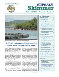
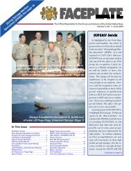
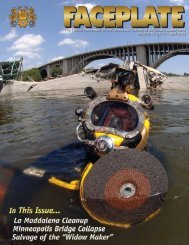
1. BackgroundEx-SHADWELL / Ex-State <strong>of</strong> Maine<strong>Salvage</strong> <strong>Report</strong>On August 31, 2005, Hurricane Katrina brought destructive storm surge <strong>and</strong>winds into Mobile Bay <strong>and</strong> caused USCG fire test vessel Ex-T/V-State <strong>of</strong> Maine (Ex-<strong>SOM</strong>AINE) <strong>and</strong> the Naval Research Laboratory (NRL) fire test vessel Ex-SHADWELL(LSD-15) to drag anchors <strong>and</strong> shift their respective moorings at Little S<strong>and</strong> Isl<strong>and</strong> inMobile AL. Ex-SHADWELL, a WWII amphibious l<strong>and</strong>ing dock ship, was movedapproximately 100 yards north <strong>and</strong> rested on the beach at the north end <strong>of</strong> the cove. Ex-SO MAINE, originally contracted by American President Lines, but was taken over by thegovernment for service as a Korean Conflict Troop Transport Ship, was driven 20 yardsnorth <strong>and</strong> 150 yards east until it rested on a s<strong>and</strong> bar at the mouth <strong>of</strong> the cove. Little S<strong>and</strong>Isl<strong>and</strong> is a man made isl<strong>and</strong> east <strong>of</strong> the main harbor channel leading to Mobile. It wasdeveloped from dredge spoils <strong>and</strong> is subject to Army Corps <strong>of</strong> Engineers (ACOE)oversight. This report will discuss the planning <strong>and</strong> extraction <strong>of</strong> the two ships <strong>and</strong> theirreturn to permanent moors in the cove <strong>of</strong> Little S<strong>and</strong> Isl<strong>and</strong>.Figure 1. Ex-SO MAINE (on the right) grounded aft <strong>and</strong> to port <strong>of</strong> her original moor.Ex-SHADWELL pushed onto the beach in this overflight following Hurricane Katrina.1
2. Ship Descriptions <strong>and</strong> StatisticsEx-USS SHADWELL (LSD-15)Authorized Lend-Lease Act As BritishMechanized Artillery Transport Tomahawk(BAPM-7)Commissioned: 07/24/1944Decommissioned: 03/09/70LOA:Beam:Max Draft:Light Displacement:Custodian:Originally, WWII USN L<strong>and</strong>ing ShipDock458 Ft72 Ft18 Ft4960 LTNRL, Fire Research Det., Little S<strong>and</strong>sIsl<strong>and</strong>, Mobile Bay, Mobile, AL2
T/V STATE OF MAINE (T-AP-198)EX-USNS UPSHUR, EX-PRESIDENT HAYESCommissioned: 12/01/52Decommissioned:LOA:Beam:Max Draft:Light Displacement:Custodian:Built by New York Shipbuilding Co. in 1951. Taken overby US Navy renamed USS Upshur <strong>and</strong> used as TroopTransport Ship during Korean Conflict. From 1973 –1997 loaned to Maine Maritime Academy renamed State<strong>of</strong> Maine. Currently, on loan from MARAD to US CoastGuard's Fire & Safety Test Detachment on Little S<strong>and</strong>Isl<strong>and</strong>, Mobile AL, for fire-fighting research1973 (end <strong>of</strong> USN troopship era)533 Ft73 Ft27 Ft6720 LtU.S. Coast Guard, Fire & Safety Test Detachment,Mobile, Al3
3. Grounding Details <strong>and</strong> Development <strong>of</strong> a PlanNaval Research Laboratory requested COMNAVSEASYSCOM salvageassistance after Hurricane Katrina via 311936Z AUG 05 NRL WASHINGTON DCMessage <strong>and</strong> on 7 September, 2005 the Coast Guard Research <strong>and</strong> Development Centerrequested salvage <strong>and</strong> recovery assistance for the Coast Guard's Fire Test Vessel, STATEOF MAINE.An initial survey was conducted in early September by SUPSALV engineersaccompanied by Donjon Marine (US Navy East Coast <strong>Salvage</strong> Contractor) <strong>and</strong> <strong>of</strong>immediate concern was the material condition <strong>of</strong> Ex-SHADWELL’s hull.Decommissioned in 1970, the ship had not been dry docked since then <strong>and</strong> had minimalmaintenance on the hull with practically no maintenance below the water line. Thecondition <strong>of</strong> Ex-SO MAINE was significantly better, due to the ship’s continuous usagethrough 1997.USS GRAPPLE (ARS-53), in theater participating in the Gulf Coast recoveryfrom Hurricane Katrina, was able to provide the first post-hurricane depth survey <strong>of</strong> thecove. This depth survey, conducted during the week <strong>of</strong> 13 September 2005 provided anindication <strong>of</strong> the amount <strong>of</strong> dredging work that would be required to refloat the ships.USS GRAPPLE also provided additional input on the material condition <strong>of</strong> the ships <strong>and</strong>a situational report on the surrounding waters. USS GRAPPLE’s Survey is included inAppendix A.On 17 October 2005, Naval Research Laboratory (NRL) <strong>of</strong>ficially requestedSUPSALV to provide salvage <strong>and</strong> recovery assistance for fire test ship Ex-SHADWELL.While the vessel was in no danger <strong>of</strong> sinking <strong>and</strong> was not a hazard to navigation, NRLrequested SUPSALV assistance to restore the vessel to its moored position in order toallow continued use as a fire test vessel. This document <strong>and</strong> other NRL <strong>and</strong> Coast Guardtasking messages are included in Appendix B.Due to the poor material condition <strong>of</strong> the hull, an in-depth survey <strong>of</strong> Ex-SHADWELL’s hull, which included Ultrasonic Testing, was conducted by GPC/PCCI(U.S. Navy contractors for ESSM support <strong>and</strong> POSSE modeling, respectively) inNovember, 2005. The survey documented considerable corrosion <strong>of</strong> the hull below thewaterline <strong>and</strong> found that the longitudinals in this same region were completely wasted atthe hull. This loss <strong>of</strong> the longitudinal stiffeners meant that much <strong>of</strong> the bottom platingwas unsupported between the frames <strong>and</strong> susceptible to buckling under compressiveloads. A copy <strong>of</strong> this survey is provided in Appendix C.Both hulls were modeled in SUPSALV’s Program for Ship <strong>Salvage</strong> Engineering(POSSE) to calculate hull stresses <strong>and</strong> to estimate the ground reaction. POSSE’sversatility allowed for hull corrosion <strong>and</strong> loss <strong>of</strong> structural support to be figured into thestrength analysis <strong>of</strong> the hull girder. In Ex-SHADWELL’s case, buckling <strong>of</strong> the bottomplating in compressive loading was the dominant failure mode <strong>of</strong> concern <strong>and</strong> the shipwas estimated to be 4088 LT aground. Ex-SO MAINE was estimated to be 1800 LTaground <strong>and</strong> the analysis yielded no significant concern for the strength <strong>of</strong> the hull girder.Based on the strength <strong>of</strong> the Ex-SO MAINE, no additional modeling was performed.SUPSALV’s concerns about Ex-SHADWELL’s structure resulted in a salvage plan thatwas developed to keep the hull girder system in tension throughout the process. The plan4
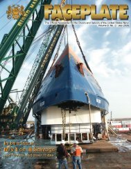
involved jetting under the hull in the middle <strong>of</strong> the vessel <strong>and</strong> then lowering the stern <strong>and</strong>finally lowering the bow when the ship was ready to float free. The POSSE model wasupdated a number <strong>of</strong> times throughout the process. The initial condition <strong>of</strong> Ex-SHADWELL is depicted in Figure 2. Follow-on models accomplished as the salvageprocess evolved are included in Appendix D.Draft/Displacement SummaryRefloatStr<strong>and</strong>ed Draft / Displacement DataIntact Direct After Outflow As Str<strong>and</strong>edDraft at FP ft 12.47 8.11Draft at AP ft 11.44 3.82Trim ft 1.03F 4.29FDraft at Fwd Marks ft 12.47 8.11Draft at Aft Marks ft 11.44 3.82Static Heel Angle deg 4P 7STotal Weight LT 5,482 5,482 5,482VCG ft 28.65 28.65 28.65LCG ft-FP 220.79A 220.79A 220.79ATCG ft-CL 0.20P 0.20P 0.20PBuoyancy LT 5,482 2,502KB ft 6.42 3.47LCB ft-FP 220.72A 205.17ATCB ft-CL 1.72P 4.66SKMt ft 31.53 69.00FSc ft 0.00 0.00GMt ft 2.88 32.23Figure 2. Ex-SHADWELL’s initial condition as modeled by PCCI using Program <strong>of</strong> Ship<strong>Salvage</strong> Engineering (POSSE).From the initial survey, a notional salvage plan was developed which called forthe use <strong>of</strong> dredging to reduce grounding forces <strong>and</strong> refloat the ships. To accomplish this5
salvage, SUPSALV assembled a team that consisted <strong>of</strong> Donjon Marine, SUPSALV’sEast Coast <strong>Salvage</strong> Contractor, local contractors (under subcontract to Donjon), GPCwho is SUPSALV’s Emergency Ship <strong>Salvage</strong> Material (ESSM) contractor, <strong>and</strong> Mobile<strong>Diving</strong> <strong>and</strong> <strong>Salvage</strong> Unit (MDSU) ONE, Det ONE. It was anticipated that MDSU ONEdivers would support the operation by assisting in jetting the hull plates under Ex-SHADWELL, assisting in clearing the dredging suctions <strong>and</strong> cutter heads as theyencountered foreign objects, <strong>and</strong> setting up <strong>and</strong> operating the beach gear to aid in pullingthe ships <strong>of</strong>f their str<strong>and</strong>s. This joint operation provided a rare real-world salvageopportunity for the MDSU divers, made use <strong>of</strong> the Navy owned ESSM <strong>Salvage</strong>equipment staged in Cheatham Annex, Virginia, <strong>and</strong> took advantage <strong>of</strong> the expertise <strong>of</strong>their east coast salvage contractor, Donjon. The joint salvage operation betweencommercial assets <strong>and</strong> U.S. Navy <strong>Salvage</strong> forces would reduce the cost <strong>of</strong> the salvageoperation to the U.S. Government <strong>and</strong> provide a valuable salvage training experience tothe U.S. Navy participants.Other Team members included:• PCCI who provided a salvage engineer to perform POSSE calculations• US Coast Guard Fire & Safety Test Detachment, Mobile, AL. Provided base forstaging equipment transport to Little S<strong>and</strong> Isl<strong>and</strong>, provided L<strong>and</strong>ing Craft forequipment transport <strong>and</strong> Personnel Boat for MDSU transport. Obtained permitsfor maintenance dredging. Provided access to Ex-SO MAINE <strong>and</strong> supportednumerous other Little S<strong>and</strong> Isl<strong>and</strong> logistics issues.• U.S. Navy Research Lab. Provided access to <strong>and</strong> support for monitoring hullgirder stresses on Ex-SHADWELL.4. <strong>Salvage</strong> PlanSUPSALV, in conjunction with Donjon, PCCI, <strong>and</strong> MDSU, developed a plan toconduct the salvage <strong>of</strong> the two fire test ships. The plan consisted <strong>of</strong>:1. Establishing a dredge spoil area on Little S<strong>and</strong> Isl<strong>and</strong>.2. Dredging under <strong>and</strong> around the ships.3. Dredging final berths for the two vessels.4. Using l<strong>and</strong> based earth removal equipment to open a channel on the port side <strong>of</strong>Ex-SHADWELL <strong>and</strong> to begin excavation to the south <strong>of</strong> to Ex-SHADWELL’s newpermanent berth.5. Using MDSU divers to keep dredging equipment free <strong>of</strong> debris <strong>and</strong> to jet s<strong>and</strong>from under the keel <strong>of</strong> Ex-SHADWELL.6. Using ESSM gear <strong>and</strong> local tugs to extract the two ships <strong>and</strong> position them intheir final moor.7. Continually monitor stresses on Ex-SHADWELL through use <strong>of</strong> a Hull GirderDeflection Monitoring System <strong>and</strong> to update the Ex-SHADWELL POSSE modelas conditions changed during the salvage process.The complete salvage plan, Titled “Refloat Concept <strong>of</strong> Operations” as developedby PCCI / GPC <strong>and</strong> Donjon on 1 December, 2005 is provided in Appendix E.6
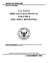
A final planning document was developed in conjunction with an on-site coordinationmeeting held prior to the start <strong>of</strong> the operation. This document, also provided inAppendix E, details the agenda <strong>of</strong> a 15-16 March 2006 planning meeting held in Mobile,AL. The document outlines the agenda, objectives, equipment required by all parties,<strong>and</strong> the final action items that needed to be resolved to ensure the operation wassuccessful.Figure 3. Chart compiled from surveys depicting the cove in Little S<strong>and</strong> Isl<strong>and</strong> after thestorm.5. Berm ConstructionBased on the initial USS GRAPPLE survey <strong>and</strong> subsequent surveys conducted byMcWIlliams, the dredging requirements were developed. The salvage plan requiredremoval <strong>of</strong> approximately 70,000 cubic yards <strong>of</strong> material. Donjon contracted with a localmarine construction firm to construct a berm large enough to contain the anticipateddredge spoils. The berm would allow the dredge slurry to settle <strong>and</strong> water to flow out aspillway. Since Little S<strong>and</strong> Isl<strong>and</strong> originated as a spoil site, the permitting process wassimplified. The US Coast Guard Fire & Safety Test Detachment, Mobile, AL applied tohave an existing permit for “maintenance dredging” reactivated.The berm construction specifications called for construction <strong>of</strong> an 11 foot highearthen wall encompassing approximately 20 acres on Little S<strong>and</strong> Isl<strong>and</strong>, Mobile, AL.(see Figure 4). The bermed area needed to be capable <strong>of</strong> accommodating 400,000 cubicyards <strong>of</strong> dredged spoil material to be removed from the mooring slip containing the Navy<strong>and</strong> Coast Guard test vessels at the isl<strong>and</strong>. The berm wall was to be constructed fromground material (i.e., s<strong>and</strong>) from the isl<strong>and</strong>. S<strong>and</strong> would be excavated along theperimeter <strong>of</strong> the berm wall <strong>and</strong> used for the wall’s construction. The berm wall had to beat least 10 feet wide at the top to allow movement <strong>of</strong> construction equipment on the walltop. The wall also had to be wide enough at the base to support the weight <strong>of</strong> s<strong>and</strong>7
created by the wall’s 11 foot height. The berm wall was sloped both on the inside <strong>and</strong>outside <strong>of</strong> the berm. The outside wall was sloped at a ratio <strong>of</strong> one foot high to three feetwide while the inside wall was built with a one to two foot slope.Figure 4. Little S<strong>and</strong> Isl<strong>and</strong>. Cove containing Ex-SO MAINE <strong>and</strong> Ex-SHADWELL to theleft. Dredge spoil area <strong>and</strong> berm location drawn in red to right. This picture was takenwell before Hurricane Katrina <strong>and</strong> the third vessel shown in the image to starboard <strong>of</strong>Ex-SO MAINE was not present at the time <strong>of</strong> the storm.While the contractor had to provide all the heavy-duty equipment <strong>and</strong> personnelneeded to construct the berm, they were <strong>of</strong>fered transport to the isl<strong>and</strong> using the CG Fire& Safety Test Detachment’s (F&STD) vessels. In support <strong>of</strong> this effort, F&STDprovided transport for the contract workers to <strong>and</strong> from the isl<strong>and</strong> each day. Transportincluded F&STD’s heavy duty transporter which was a 74 foot L<strong>and</strong>ing CraftMechanized (LCM-8) with a motorized front l<strong>and</strong>ing gate. The cargo bay <strong>of</strong> the LCM-8is approximately 14 feet 5-inches wide, 42-feet long, <strong>and</strong> capable <strong>of</strong> transporting up to120,000 pounds. Additionally, a 35-foot workboat <strong>and</strong> two 24-foot small boats were alsoavailable for transporting personnel. Each small boat could accommodate 10 people.8
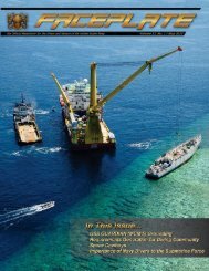
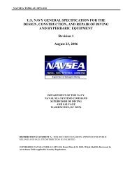
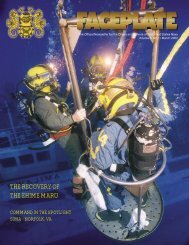
Figure 5. Coast Guard Fire <strong>and</strong> Safety Test Division transport vessel (LCM-8)delivering supplies to Little S<strong>and</strong> Isl<strong>and</strong>.6. Dredging <strong>and</strong> L<strong>and</strong>-Based Earth RemovalAfter completion <strong>of</strong> the spoil basin, the task <strong>of</strong> dredging began. The objectiveswere to:1. Remove sufficient material to allow for the extraction <strong>of</strong> both the Ex-SHADWELL<strong>and</strong> Ex-SO MAINE.2. Create two deepwater slips for both the Ex-SHADWELL <strong>and</strong> Ex-SO MAINE witha mound in between <strong>and</strong> to the “<strong>of</strong>fshore sides” so that, except in the mostextreme weather conditions, the vessels “slips”, in conjunction with their mooringsystems, will ensure they remain in their prescribed locations. The higherelevations outside the vessels’ slips will substantially assist in this effort.The large dredge arrived on site on 10 April 2006 <strong>and</strong> worked through 26 June.This machine pumped through a 15” diameter pipe to the spoil site. The dredge wasstaffed to work 24-hour operations. As the dredge began work in the cove, metallicdebris was <strong>of</strong>ten encountered. This included old mooring chain, wire rope, pilings, <strong>and</strong>other miscellaneous debris. Encountering this material with a dredge cutter head resultedin down time while the equipment operators, <strong>of</strong>ten in conjunction with MDSU divers,cleared the dredge pumps, cutter head or suction pipes. Occasionally, damage resultedfrom the entanglement <strong>and</strong> supplies were required to return the equipment to operation.Figure 6 is an image <strong>of</strong> the dredge working on the starboard side <strong>of</strong> the Ex-SO MAINE.Figure 7 is an image <strong>of</strong> the cutter head <strong>of</strong> the dredge being cleared <strong>of</strong> debris by its crew.9
Figure 6. Large Dredge working the starboard side <strong>of</strong> State <strong>of</strong> MaineFigure 7. MDSU <strong>and</strong> dredge operators work to clear large dredge cutter head <strong>of</strong> debrisencountered during dredging operationsIn order to complete the dredging, Donjon eventually ordered a second dredge tothe site. The second dredge worked from 3 May through 15 June <strong>and</strong> was instrumental incombating the high concentration <strong>of</strong> clay that occupied the cove under Ex-SHADWELL<strong>and</strong> Ex-SO MAINE. Figure 8 is a picture <strong>of</strong> the smaller dredge working under the portquarter <strong>of</strong> Ex-SHADWELL on the 1 June 2006.10
Figure 8. Small Dredge clearing a channel on the port quarter <strong>of</strong> Ex-SHADWELLDredge spoils were pumped to the center <strong>of</strong> the bermed area where earth movingequipment tended the outflow pipes, monitored the outfall <strong>and</strong> graded dried s<strong>and</strong> t<strong>of</strong>acilitate the containment <strong>of</strong> the dredge spoil. The large earth moving equipment on theisl<strong>and</strong> moved the spoils <strong>and</strong> the outflow pipes around the bermed area to ensure all thespace inside the berm was effectively utilized. Figure 9 is an image <strong>of</strong> the spoil site. Theimage shows the outflow pipes, piled up spoil, <strong>and</strong> the berm, nearly filled with water inthe background.The earth moving equipment also supported the dredging efforts two additionalways. The first was by removing earth adjacent to Ex-SHADWELL’s port side as she saton the beach. At the beginning <strong>of</strong> the operation, Ex-SHADWELL port side sat over hards<strong>and</strong>. The excavator cleared enough material to allow the small dredge to begin workingthe port side <strong>of</strong> the hull. By mid-June, the large dredge was also able to work on Ex-SHADWELL’s port side.The second dredging operation undertaken by the earth moving equipment was tohelp prepare the new moor for Ex-SHADWELL. During the week <strong>of</strong> 8 May, 2006 anexcavator began pulling s<strong>and</strong> out <strong>of</strong> the shallows on the south west side <strong>of</strong> the cove. Thisportion <strong>of</strong> the cove had been filled in by Katrina <strong>and</strong> required clearing to allow Ex-SHADWELL into its prescribed moor. As the excavator dug, the shoreline shifted south.The s<strong>and</strong> that was removed was pushed <strong>and</strong> graded by a bulldozer <strong>and</strong> evolved into asubstantial dune which would help shield Ex-SHADWELL from potential southerlyblows. Figure 10 is an image <strong>of</strong> the s<strong>and</strong> piles being excavated <strong>and</strong> pushed up into dunes.11
Figure 9 Little S<strong>and</strong> Isl<strong>and</strong> spoil site. Earth moving equipment arranging s<strong>and</strong> during adredging break.Figure 10. South West corner <strong>of</strong> the cove on Little S<strong>and</strong> Isl<strong>and</strong>. Machinery moving s<strong>and</strong>removed from Ex-SHADWELL’s planned moor.7. Laser Hull Girder Deflection Monitoring SystemConcern for the potential <strong>of</strong> local failure through plate buckling resulted in thedevelopment <strong>of</strong> a system to monitor very small deflections <strong>of</strong> Ex-SHADWELL’s hull.This system, the Hull Girder Laser Monitoring System, used a surveyor’s laser level <strong>and</strong>12
a laser sensing target to measure changes in the hull at multiple pre-defined points, whichwere then be used to calculate stress in the hull. Ex-SHADWELL’s well deck was open<strong>and</strong> large enough to set the system up. The rotating laser was fixed in the center <strong>of</strong> thewell deck <strong>and</strong> sixteen measurement points were established. The measurement pointsestablished hull deflection conditions at frames 22, 36, 74, 88, 101 <strong>and</strong> 111.Measurements could be collected in less than 30 minutes <strong>and</strong> the system proved accurateto within 1/16-inch over the length <strong>of</strong> the well deck. Figure 11 contains a photo <strong>of</strong> therotating laser level <strong>and</strong> one <strong>of</strong> the measurement points. Appendix F. contains severalspreadsheets depicting hull deflection readings from Ex-SHADWELL.Figure 11. Davis White rotating laser level (to the right) <strong>and</strong> receiver/measurement pointto the left (highlighted by arrow) in well deck <strong>of</strong> Ex-SHADWELL8. T/V STATE OF MAINE ExtractionEx-SO MAINE was grounded aft with the bow cantilevered over the ship’sprevious mooring position. The plan was to first, dress up the permanent moor berth withthe dredge. Then dredging was to be concentrated at the stern until the ground force wasestimated to be reduced to 150 LT. This would allow beach gear or beach gear <strong>and</strong> tugcombination to pull the ship free <strong>of</strong> the bar <strong>and</strong> then have the tugs reposition Ex-<strong>SOM</strong>AINE in its moor. MDSU set up beach gear running from the starboard anchor hawsehole leading forward <strong>and</strong> starboard to shore <strong>and</strong> a second leg leading nearlyperpendicular <strong>of</strong>f the starboard side (see Figure 12). Each <strong>of</strong> these legs <strong>of</strong> U.S. NavySt<strong>and</strong>ard Beach Gear consisted <strong>of</strong> the following: 6,000 pound Lightweight Anchor, oneshot 2-1/4” chain, spools <strong>of</strong> 1-5/8” wire rope (300 or 600 feet), <strong>and</strong> a hydraulic puller.After dredging at the stern <strong>and</strong> starboard side for nearly 30 days (10 April – 9 May minus13
dredge down time) an attempt was made to pull Ex-SO MAINE free <strong>of</strong> her st<strong>and</strong>. Nearly100,000 lbs <strong>of</strong> pull was achieved with the starboard bow hydraulic puller but nomovement was detected. On 10 May, a strong southerly was blowing water to the northend <strong>of</strong> Mobile Bay raising the water level above the normal high tide <strong>and</strong> two CrescentTugs were engaged try to shift Ex-SO MAINE’s stern to starboard. The tugs effort inconjunction with the single leg <strong>of</strong> beach gear failed to shift Ex-SO MAINE that day s<strong>of</strong>urther dredging was employed.Figure 12. Excavator assisting MDSU ONE team in setting the anchor in a deadman. Inforeground is the bridle assembly <strong>and</strong> 50-ton hydraulic cable puller <strong>and</strong> to the left is thecontrol panel <strong>and</strong> new electronic tension measuring device.The second leg <strong>of</strong> beach gear was deployed on 11 May <strong>and</strong> tensioned, confirmingthe anchor was set. By 14 May, 24 hour a day dredge operations had completed a trench30 ft deep along the grounded length <strong>of</strong> the hull on both the port <strong>and</strong> starboard side <strong>and</strong>on 15 May the ship refloated following the collapse <strong>of</strong> the remaining supporting groundmaterial. The hull was positioned in the mooring location designated by the USCG FS&TDet in Little S<strong>and</strong> Isl<strong>and</strong> Cove, which approximates the pre-str<strong>and</strong>ing position. Atemporary moor was established using ship's port <strong>and</strong> starboard bow anchors set on theshore <strong>and</strong> one stern mooring leg. One additional mooring leg is being readied fordeployment following completion <strong>of</strong> Ex-SHADWELL ops. GPC began packing up much<strong>of</strong> the ESSM gear deployed for the operation including the U.S. Navy St<strong>and</strong>ard BeachGear <strong>and</strong> the Hydraulic Pulling engines. This material was returned to Cheatham Annex<strong>and</strong> the remaining ESSM gear, left on site for the Ex-<strong>Shadwell</strong> extraction, is identified inAppendix I, “Remaining ESSM Gear to Support <strong>Salvage</strong> Operations in Mobile AL”.14
Figure 13. Two Crescent Towing tugs attempting to free Ex-SO MAINE from str<strong>and</strong> on10 May 2006. Ex-SO MAINE finally floated free on 15 May after additional dredging.9. Ex-SHADWELL ExtractionHurricane Katrina pushed Ex-SHADWELL on the beach. Her port side was sittingover dry s<strong>and</strong> <strong>and</strong> her bow was firmly pined on the beach. Figure 14 shows Ex-SHADWELL after the storm <strong>and</strong> at the beginning <strong>of</strong> the l<strong>and</strong>-based excavation. Ex-SHADWELL’S extraction began on 7 April with excavators <strong>and</strong> bulldozers beginning toremove earth from the port side <strong>of</strong> the hull.Figure 14. Ex-SHADWELL hard aground <strong>and</strong> at the beginning <strong>of</strong> l<strong>and</strong> based excavation.Because <strong>of</strong> Ex-SHADWELL’s degraded longitudinal stringers <strong>and</strong> the potential forthe hull plates to buckle under additional stress, the salvors carefully planned herextraction to maintain tension on her hull girder system. Flooding alarms were installed(components from the ESSM Towing System) on 10 April <strong>and</strong> the Laser Hull GirderMonitoring System was set up on 12 April to track changes in hull stress.15
By 21 April, shore-based excavation on the port side was complete <strong>and</strong> on 26April, MDSU One divers began jetting s<strong>and</strong> out from under the hull between frames 24<strong>and</strong> 76. This was done to place the center <strong>of</strong> the hull in tension <strong>and</strong> not increase anypressure on the plates <strong>and</strong> hull girders.On April 26 th , SUPSALV placed a second dredge on contract <strong>and</strong> beganextracting s<strong>and</strong> <strong>and</strong> mud along the port <strong>and</strong> starboard quarters on Ex-SHADWELL. Thelarge dredge was generally working on the Ex-SO MAINE extraction <strong>and</strong> dredging thecove where the two vessels would be permanently moored once extracted.When Ex-SO MAINE floated free on 15 May, both dredges concentrated on Ex-SHADWELL alternating between Ex-SHADWELL <strong>and</strong> the site <strong>of</strong> the permanent moor.On 19 May pilings associated with an old service platform were discovered just to thenorth <strong>of</strong> Ex-SHADWELL’s planned permanent moor. It was decided to remove theportion <strong>of</strong> the platform above the cove bottom but not to remove its foundation becausethere was enough space between the service platform <strong>and</strong> the cove shoreline for themoored vessel.Back on Ex-SHADWELL, the shore side digging <strong>and</strong> small dredging had increasedthe clearance on the port side to allow the large dredge to work both sides <strong>of</strong> the hull.MDSU One divers set up their diving barge forward on Ex SHADWELL on 19 May <strong>and</strong>began jetting under the hull between frames 15 <strong>and</strong> 29 <strong>and</strong> completed jetting betweenframes 29 <strong>and</strong> 85.On 12 June, after nearly continuous dredging with both dredges since 15 May,Ex-SHADWELL’s list dropped from 11 degrees starboard to 6 degrees starboard.Dredging continued <strong>and</strong> MDSU divers were routinely engaged in removing obstructionsfrom the dredge paths to keep those systems in operation. On 16 June, Ex-SHADWELLshifted from 7 degrees starboard to 0.5 degrees port. Attempts to push Ex-SHADWELLfree using the Utility Tug that was providing daily support were unsuccessful. The largedredge re-engaged the clay on the starboard side <strong>of</strong> Ex SHADWELL <strong>and</strong> after two days<strong>of</strong> downtime for repairs on 21 <strong>and</strong> 22 June, the dredge continued working starboard side,from the stern forward to amidships, digging at the 33-foot level <strong>and</strong> then the 25 footlevel. The ship continued to rest on a shelf along the centerline <strong>of</strong> the hull. It wasanticipated that this shelf would fall away as its base was removed by the dredge.Analysis <strong>of</strong> tidal predictions indicated that a period <strong>of</strong> more extreme tides wasapproaching <strong>and</strong> would peak during this 24 – 27 June time frame. The salvage team washoping that their dredging efforts would allow them to take advantage <strong>of</strong> these high tides.A copy <strong>of</strong> the predicted tides for May <strong>and</strong> June are provided in Appendix G. The tidetables clearly show the key role the monthly tide cycle played on the days both Ex-<strong>SOM</strong>AINE <strong>and</strong> Ex-SHADWELL floated free <strong>of</strong> their str<strong>and</strong>s.On 26 June at 1045, more than an hour earlier than predicted, Ex-SHADWELLfloated free <strong>and</strong> local tugs were used to pull the ship out <strong>of</strong> the cove, rotate her 180degrees in the shipping channel <strong>and</strong> push her back the into her permanent mooring on thesouth end <strong>of</strong> the cove on the Little S<strong>and</strong> Isl<strong>and</strong>. This moor, as diagrammed in Figure 15,was at the south end <strong>of</strong> the cove <strong>and</strong> well separated from Ex-SO MAINE whose shifttoward Ex-SHADWELL during Hurricane Katrina may have contributed to her mooringsystem failure.16
Following the setting <strong>of</strong> the permanent moor, PCCI was tasked with performing amooring analysis for the final Ex-SHADWELL moor. That analysis concluded that it waspossible that the ship would shift in its moor with strong northerly or southerly winds.Furthermore, they noted that if a significant storm surge did not accompany the wind, itwas likely that the sides <strong>of</strong> the dredged channel would assist in keeping the ship in itsmoor. That Mooring Analysis report is included in Appendix H.Two FWD legs are ship’s original bowanchors. Two AFT stern <strong>and</strong> four breast legsare made up <strong>of</strong> buried 7,000 to 10,000lbanchor dead-men with approx 100 feet <strong>of</strong> 2-1/4 to 2-3/4 inch stud or die-lock chainshackled into 10 inch nylon hawsers,attached to the ship mooring bitts.Approx 40Concreteobstructionat depth<strong>of</strong>12 FTInstalledBow FR 11FR 22FR 59 FR 100Figure 15. Ex-SHADWELL permanent mooring plan10. Funding - Cost <strong>of</strong> OperationOriginal tasking required separate identification <strong>of</strong> funding requirements for Ex-SHADWELL <strong>and</strong> Ex-SO MAINE so SUPSALV developed funding estimates for each <strong>of</strong>the tasks. Eventually, NRL indicated that they would pay the entire cost <strong>of</strong> the operation<strong>and</strong> then they would bill the Coast Guard for their share. This simplified the accountingtask for SUPSALV who prorated costs to Ex-SO MAINE as a percentage <strong>of</strong> the totalcosts. Costs for each area <strong>of</strong> support for the operation are identified in Figure 15 <strong>and</strong> thebreakdown <strong>of</strong> costs between Ex-SHADWELL <strong>and</strong> Ex-SO MAINE is provided in Figure16.17
<strong>Final</strong> CostFundsAppropiatedObligationsUSCG HSCG3206XE00011 $15,249.00 N0002403D4202 10 $10,000.00GPC PCCI & ESSM Support $269,308.00Site Survey included above N0002401D4018 856 $5,249.00Hull UT Inspection included abovePOSSE Model SHADWELL included above NRL N0017306RC00013 $30,996.00 N0002401D4018 856 $20,996.00POSSE Model <strong>SOM</strong> included aboveLaser Hull Girder Deflection System included above N0002403D4202 10 $10,000.00ESSM Equipment & Operators included aboveSHADWELL Mooring Design included above NRL N0017306RC00049 $1,778,357.00 N0002401D4018 856 $5,330.00<strong>SOM</strong> Mooring Design $0.00N0002401D4018 856 $97,233.00DONJON Support $2,751,510.30<strong>Salvage</strong> Master included above N0002403D4202 10 $1,557,066.00Dredge Barges included aboveFloating Crane w/H<strong>and</strong>ling Tug included above N0002401D4018 856 $30,000.00Harbor Tugs included aboveEarth Moving Equipment included above N0017306RC00049.03 $150,000.00 N0002403D4202 10 $79,500.00Berm Construction included aboveN0002401D4018 856 $70,500.00N0017306RC00049.04 $764,301.76 N0002403D4202 10 $740,500.00N0002401D4018 856 $25,000.00SUPSALV Support/Travel $0.00N0017306RC00049.05 $500,000.00 N0002403D4202 10 $416,282.00N0002401D4018 856 $15,000.00TOTAL w/out MDSU: $3,020,818.30 Total: $3,238,903.76 Total: $3,082,656.00Total Funds Not Used: $218,085.46 Unobligated Funds $156,247.76MDSU ONE Support $85,000.00 NRL direct to MDSU $100,000.00MDSU Extension $15,000.00Total Cost: $3,120,818.30Figure 16. Costing data for the extraction project.18
Agency <strong>Shadwell</strong> St. <strong>of</strong> MaineContractDelivery Orde CATEGORY TOTAL COST COSTDONJONMARINE CO.,INC. 0010SubcontractorsC&C Marine/Large Dredge $1,932,000.23 $1,257,790.81 $674,209.42Construction Solutions/Crane Barge $321,335.91 $208,856.13 $112,479.78Lott Enterprises/small dredge $221,974.43 $170,096.35 $51,878.08Beard Equipment/Ground Equpment $12,493.93 $9,624.85 $2,869.08Crescent Towing/Tugs $14,368.35 $9,229.60 $5,138.75Others/Fuel, supplies, consumables $4,155.07 $2,432.70 $1,722.37PCCI, Inc./Engineering Support $101,652.56 $76,652.56 $25,000.00Subtotal $2,607,980.48 $1,734,683.00 $873,297.48SCH LABOR $99,493.22 $72,052.30 $27,440.92NONSCH LABOR $10,496.48 $5,248.24 $5,248.24PERDIEM $12,467.91 $8,729.59 $3,738.32TRANSPORT $7,985.17 $5,283.52 $2,701.65MISC $13,097.04 $10,624.34 $2,472.70Delivery Order Total $2,751,520.30 $1,836,620.99 $914,899.31GPC, JointVenture0856Subcontractor $9,234.00 $6,463.80 $2,770.20Engineering Labor $50,601.45 $36,892.05 $13,709.40GPC labor $90,785.00 $63,549.50 $27,235.50Travel/PerDiem $37,262.00 $26,083.40 $11,178.60Transportation Equipment $27,914.00 $19,539.80 $8,374.20Supplies/Material $16,272.00 $11,390.40 $4,881.60Material Serv. On Order $8,211.00 $5,747.70 $2,463.30Material On Order $4,546.00 $3,182.20 $1,363.80Award Fee $24,482.55 $17,284.89 $7,197.66Delivery Order Total $269,308.00 $190,133.74 $79,174.26MDSU $123,861.01 $83,861.01 $40,000.00Project Total $3,144,689.31 $2,110,615.74 $1,034,073.57Figure 17. Cost breakdown between Ex-SHADWELL <strong>and</strong> Ex-SO MAINE.19
calculated ground reaction, was obviously unable to refloat the ship. Progressivelydeeper cuts were required in order to free the hull. This extended the duration <strong>of</strong> theoverall salvage operation.MDSU OneMDSU participated in this salvage task as a training opportunity for the memberswho deployed to Alabama. Setting up two sets <strong>of</strong> beach gear on the Ex-SO MAINE <strong>and</strong>placing a load on the gear was an excellent practical exercise although it was not clearthat the beach gear played a role in freeing Ex-SO MAINE from its str<strong>and</strong>.A key MDSU task was the the jetting <strong>of</strong> mud under the hull <strong>of</strong> EX-SHADWELL.This task was an integral part <strong>of</strong> the salvage plan. It reduced the ground reaction <strong>of</strong> thehull <strong>and</strong> ensured the keel was kept in tension, easing the pressure on the fragile hullplates <strong>and</strong> structureMDSU was on site from 1 April through 7 June 2006. In addition to the jettingtask <strong>and</strong> the beach gear setup exercise, MDSU divers supported the dredging operationswith almost daily dives to clear the dredge <strong>of</strong> debris or to locate <strong>and</strong> identify debrisencountered by the dredges <strong>and</strong> rig that debris for removal. Other than when performingthe two planned salvage support tasks, it was difficult to keep the team fully employeduntil the dredges encountered a new item <strong>of</strong> debris in its path This was a minor timemanagement efficiency issue.ESSMAppendix I contains a detailed list <strong>of</strong> equipment ESSM provided to support thisoperation. Appendix I also includes a list <strong>of</strong> equipment that was retained after Ex-<strong>SOM</strong>AINE extraction <strong>and</strong> positioning at her permanent moor. As a part <strong>of</strong> providing <strong>and</strong>maintaining this equipment for the duration <strong>of</strong> the operation, a number <strong>of</strong> issues came tolight <strong>and</strong> lessons resulting from those issues are identified below:• Equipment Repair Kits: Evaluate Configuration to support extendedoperations.• RHIB: Equipment Configuration & Trailer needed to support longdistance tow <strong>and</strong> long term operations. The bladders were worn <strong>and</strong> onehad to be re-pressurized regularly.• Small Electric Generators: ESSM should purchase h<strong>and</strong> carry model forportable operations.• Pump & Hose Fittings: Complete conversion to Camlock compatiblesystem.• <strong>Salvage</strong> Rigging Van: Develop a Field Kit• Local Fuel Loading <strong>and</strong> Storage Requirements• Shipboard Welding Kit – Purchase/stock kit for portable above waterwelding.00C StaffSUPSALV salvors should have a kit <strong>of</strong> gear to support remote operations. This kitshould include a marine b<strong>and</strong> VHF radio, a h<strong>and</strong>held GPS, <strong>and</strong> a digital camera. The21
NMCI provided laptops outfitted with Verizon Cards provided satisfactory remoteelectronic communications.12. ConclusionEx-SHADWELL <strong>and</strong> Ex-SO MAINE were extracted from their str<strong>and</strong> <strong>and</strong>positioned in their final mooring locations <strong>and</strong> all mooring equipment has beenpositioned to meet the customer's requirements. Little S<strong>and</strong> Isl<strong>and</strong>’s cove has beendredged to support the permanent moors. All salvage equipment has been removed fromthe isl<strong>and</strong>, loaded on to trucks, <strong>and</strong> is being transported back to the ESSM warehouse.Certification <strong>of</strong> Delivery letters were provided to customer reps for both ships <strong>and</strong> areincluded as Appendix J. A copy <strong>of</strong> the timeline for this operation is included inAppendix K. Text from the Situation <strong>Report</strong> Messages, issued three times a week, areincluded as Appendix L. This Timeline <strong>and</strong> the Situation <strong>Report</strong>s document thedetermination <strong>and</strong> perseverance <strong>of</strong> the project team who steadfastly resolved the manyobstacles encountered in order to complete the successful salvage operation. GPC’s finalreport for Operational Delivery Order #0856/S116 is provided as Appendix M. Abriefing conducted after the operation highlights many <strong>of</strong> the challenges <strong>of</strong> the tasks <strong>and</strong>provides additional photos <strong>of</strong> the operations. This brief is provided as Appendix N.Figure 18. Ex SHADWELL <strong>and</strong> Ex-SO MAINE moored in their final positions.22
Appendix Aex-STATE OF MAINE SALVAGE SURVEYLT Shaun P. Hayes, USNRUSS GRAPPLE (ARS 53)
TABLE OF CONTENTSSALVAGE SURVEY.................................................................................................................... 3ACTION TAKEN TO DATE......................................................................................................... 5SITE SURVEY ............................................................................................................................... 6EXTERNAL CASUALTY SURVEY ............................................................................................ 7INTERNAL CASUALTY SURVEY ............................................................................................. 8AUXILIARY MACHINERY SUMMARY ................................................................................... 9DECK MACHINERY SUMMARY............................................................................................. 10BOAT SUMMARY...................................................................................................................... 11CARGO SUMMARY................................................................................................................... 12LIQUID LOAD SUMMARY....................................................................................................... 13FLOODING SUMMARY ............................................................................................................ 14Enclosure 1: ex-STATE OF MAINE Initial Survey Photographs................................................. 1Enclosure 2: ex-STATE OF MAINE Soundings (13SEP05/1900Z)............................................. 1Enclosure 3: Little S<strong>and</strong>s Isl<strong>and</strong> Inlet Soundings .......................................................................... 1Enclosure 4: ex-STATE OF MAINE Soundings (Pre-KATRINA) .............................................. 1TABLE OF FIGURESFigure 1: ex-SHADWELL / ex-STATE OF MAINE before Hurricane Katrina........................... 1Figure 2: ex-SHADWELL / ex-STATE OF MAINE after Hurricane Katrina.............................. 1Figure 3: Structural damage to ex-STATE OF MAINE................................................................ 2Figure 4: Starboard Side <strong>of</strong> ex-STATE OF MAINE ..................................................................... 2Figure 5: ex-STATE OF MAINE rudder from port side ............................................................... 3Figure 6: ex-STATE OF MAINE rudder from starboard side....................................................... 3Figure 7: ex-STATE OF MAINE Bow View................................................................................ 4Figure 8: Starboard side <strong>of</strong> ex-STATE OF MAINE...................................................................... 4Figure 9: ex-STATE OF MAINE Port Main Deck........................................................................ 5Figure 10: ex-STATE OF MAINE Starboard Main Deck............................................................. 5Figure 11: ex-STATE OF MAINE Foc'sle .................................................................................... 6Figure 12: ex-STATE OF MAINE Aft Gypsy Heads ................................................................... 6Figure 13: ex-STATE OF MAINE Starboard Aft Bits.................................................................. 7Figure 14: ex-STATE OF MAINE Port Aft Bits........................................................................... 7Figure 15: ex-SHADWELL/ex-STATE OF MAINE Soundings After Katrina............................ 1Figure 16: ex-STATE OF MAINE Sounding Before Katrina....................................................... 12
SALVAGE SURVEYGeneral Information:Type <strong>of</strong> Casualty:Str<strong>and</strong>ingDate/time <strong>of</strong> casualty: Hurricane KATRINA, August 2005Ship’s name:ex-STATE OF MAINEHull type:BARRETT Class TransportBuilder: New York Shipbuilding Corp. Camden, N.J. Year: 1952Flag:United StatesHull or Pennant # (Naval)/Official # <strong>and</strong> Builder’s (merchant): AP-198Homport:Little S<strong>and</strong>s Isl<strong>and</strong> Mobile Bay, Mobile AlabamaPlanning Yard (USN):UnknownOwner:Custodian Fire Research Detachment Little S<strong>and</strong>s Isl<strong>and</strong> Mobile Bay, Mobile, ALISIC (Naval)/Agent (merchant): Not applicableLocal Contact: CWO Quincy Merriweather, USCG – (251) 441-5040Location (area name):Little S<strong>and</strong>s Isl<strong>and</strong> Mobile Bay, Mobile Alabama(coordinates):approximately 30° 30.7’ N 088° 01.7’ WNearest Port: Mobile, Alabama Distance: NegligibleNearest U.S. or Allied Naval facility:Naval Station Pascagoula- 58 Nm (sea) / 44 mi (l<strong>and</strong>)Nearest major U.S. or Allied Naval station/repair facility:Naval Station Ingelside- 605 Nm (sea) / 681 mi (l<strong>and</strong>)Naval Station Mayport- 1000 Nm (sea) / 425 mi (l<strong>and</strong>)Crew Status:Not applicableHazardous Cargo?Numerous miscellaneous hazardouscargo onboard. Many <strong>of</strong> themiscellaneous HAZMAT distributed Spill? Possiblethroughout the ship in individualcontainersOil spill or other pollution occurred or likely?PossiblePrincipal characteristics <strong>of</strong> casualty:LBP: Unknown LOA: 534’ Beam: 73’Light Draft (original)Seagoing Loaded (original)Normal service draft: Unknown 27’ (original)Displacement: 11230 tons (original) 17630 tons (original)Deadweight:6400 tons (original)Number <strong>of</strong> Tanks/Holds:UnknownPropulsion:UnknownFraming system/significant structural details: UnknownBrief descriptions <strong>of</strong> casualty, pre-casualty condition, cargo load, major damage, <strong>and</strong> ship’s overall condition:No signs <strong>of</strong> damage to hull from external survey conducted. Small damage toDamage (hull/structural): added-on ladder <strong>and</strong> porthole on port side near main deck from apparent collisionwith ex-SHADWELL. See Enclosure 1, Figure 3 & 4.Machinery (condition/status): Unknown.Flooding:No signs <strong>of</strong> flooding caused by str<strong>and</strong>ing from external survey conducted.Fire:Used as fire research facility. No fires appear to have been caused by str<strong>and</strong>ing.Aim/intent <strong>of</strong> salvage operation:Debeach ex-STATE OF MAINE into a dredged moor on Little S<strong>and</strong>s Isl<strong>and</strong>Mobile Bay, Mobile AlabamaAvailable Assets:On-scene:In-area:USCG Group MobileUSS GRAPPLE (ARS 53)Mobile <strong>Diving</strong> <strong>and</strong> <strong>Salvage</strong> Unit Two detachments in theaterOther assets:Drawings <strong>and</strong> documents available:General Arrangments Unknown Lines Unknown3
Secrion Scantlings Unknown Shell Expansion UnknownDC Book Unknown DC Plates UnknownLiquid Load Diagram Unknown Flooding Effect Diagram UnknownDraft Diagram Unknown Ship’s Information Book UnknownBonjean’s Curves Unknown Structural Plans UnknownSounding/Ullage Tables Unknown Capacity Plan UnknownDeadweight Scale Unknown Trim <strong>and</strong> Stability Book UnknownStowage/Load Plan Unknown Cargo Manifest UnknownDeck Log Unknown Engineer’s Log UnknownPre-casualty stability information known or available from plans/documents:KG Unknown KM Unknown TPI Unknown MTI UnknownComments: NoneBefore Str<strong>and</strong>ingAfter Str<strong>and</strong>ingDrafts:13SEP05, 1900ZFwd: Unknown 18’ 9” (18’ 6” PORT/ 19’ STBD)Aft: Unknown 18’ 6” (approximated)Hog/Sag: Unknown UnknownDisplacement: Unknown UnknownTrim: Unknown UnknownList: Unknown Visible starboard list <strong>of</strong> unknownamountHeading: Unknown 072T (calculated from GPS data)Engine Order: None NoneLoading Summary* Unknown UnknownSolid Cargo: Unknown UnknownLiquid Cargo: Unknown UnknownFuel: Unknown UnknownLube Oil: Unknown UnknownFeed Water: Unknown UnknownPortable Water: Unknown UnknownWater Ballast: Unknown UnknownPermanent Ballast: Unknown UnknownAmmunition/Explosives Unknown UnknownFlooding Summary* Unknown UnknownCourse/speed at time <strong>of</strong> str<strong>and</strong>ing: None/NonePosition <strong>of</strong> rudder at time <strong>of</strong> str<strong>and</strong>ing: Amidships. See Enclosure 1, Figure 5 & 6.* See attached sheet(s) for detailed loading/flooding accounting4
ACTION TAKEN TO DATEDate: Accomplished by: Action:Unknown Unknown Anchors Laid Out: Mooring chain laid out for berth prior to Hurricane Katrina.See Enclosure 1, Figure 7 & 8.Unknown Unknown Ship Ballasted: UnknownUnknown Unknown Ship Lightened: UnknownUnknown Unknown Weight Shifts/Changes: Unknown5
SITE SURVEYCasualty exposed to:Swell:Seas:Wind:Currents:Weather Temperature:Type <strong>and</strong> range <strong>of</strong> tide:Bottom:Material:Slope:Topography:Beach Survey Conducted?Access:to the wreck site:to the wreck:to beach/shore:General Site Description:Exposure:Weather:Access to Deep Water:Weather forecasts available?Tides tables available?Current predictionsavailable?Current Effects:Scouring:Silting/S<strong>and</strong> Buildup?Via Mobile shipping channel (approx. depth <strong>of</strong> 45 feet)Added-on platform <strong>and</strong> ladders on starboard sideVia Mobile shipping channel (approx. depth <strong>of</strong> 45 feet)Tide gage set up?Current monitored?(height/period)(height/period, breaking?)(speed/direction)(surface, speed/direction)(subsurface, speed/direction)From discussion with local USCG personnel, <strong>and</strong> from depth contour informationprovided by USCG, it appears there has been no historical scouring effect bycurrent.From discussion with local USCG personnel <strong>and</strong> from depth contour informationprovided by USCG, current appears to historically cause s<strong>and</strong> buildup in the LittleS<strong>and</strong> Isl<strong>and</strong> inlet. Additionally, from the depth contour information provided bylocal USCG personnel <strong>and</strong> from GRAPPLE’s own soundings, it appearsHurricane Katrina has caused a build up <strong>of</strong> at least 3 to 4 feet <strong>of</strong> s<strong>and</strong> in the LittleS<strong>and</strong> Isl<strong>and</strong> inlet.Accurate large scale chart, recent edition, covering salvage site available?Area around casualty <strong>and</strong> channel to deep water sounded?Pollution note:Description:None observed during initial external survey.Magnitude:Source:Attach sketch showing position/orientation <strong>of</strong> casualty relative to shoreline, obstructions, hazards, deep water; channel to deep water; soundings;any anchors laid out; extent <strong>of</strong> any pollution <strong>and</strong> containment efforts, etc.6
EXTERNAL CASUALTY SURVEYDate/Time: September 13, 2005 1900ZDive Survey: None conducted <strong>Supervisor</strong>: N/APhotographs, video tapes, sonar traces, etc., available? See Enclosure ????Aground over what length(s):UnknownSettled into bottom? Yes Machinery Suctions clear? All visible appear clearSoundings:Distance from Bow: Port Starboard0 Ft 20’ 18’ 6”1 st chock on hull <strong>of</strong> ex-STATE OF MAINE 20’ 16’ 6”2 nd chock on hull <strong>of</strong> ex-STATE OF MAINE 20’ 6” 15’ 5”3 rd chock on hull <strong>of</strong> ex-STATE OF MAINE 21’ 11’4 th chock on hull <strong>of</strong> ex-STATE OF MAINE 15’ 12’Double Water Tight Doors (3 rd Level) 15’ 12’5 th chock on hull <strong>of</strong> ex-STATE OF MAINE 15’ 12’6 th chock on hull <strong>of</strong> ex-STATE OF MAINE 15’ 13’7 th chock on hull <strong>of</strong> ex-STATE OF MAINE 12’ 6” 12’Stern point <strong>of</strong> rudder 6’ 6’External Damage:General Position/Attitude/Damage: Ex-STATE OF MAINE appears to have twisted to starboard during thesurge <strong>of</strong> Hurricane Katrina. Based on the soundings above, it appearsthat she may still be floating in the bow but she most likely ran agroundaft due to the twist.Cargo leaking/spilling from hull ruptures: None observed during initial external survey (13SEP05)Propeller(s) <strong>and</strong> Shaft(s):1 Propeller1 <strong>and</strong> 1 ShaftRudder: 1Hatches <strong>and</strong> W/T Closures:Three sets <strong>of</strong> double water tight doors on the hull on both sides <strong>of</strong> ex-STATE OF MAINE. Numerous water tight doors above the main deckhave rusted in the closed position.Potential removable weights:Object Location Approximate WeightMany potential removable weights topside, seeEnclosure 1, Figures 9-11.Lifting points: Due to size <strong>of</strong> ex-STATE OF MAINE, lifting appears to be impracticablePulling points: See Enclosure 1, Figures 12-14.Attach sketches or copy <strong>of</strong> arrangement plans showing damage to shell plating, superstructure <strong>and</strong> decks, mudline,portions <strong>of</strong> ship aground. Scaled underwater pr<strong>of</strong>iles for U.S. Navy hulls can be found in Chapter 2 <strong>of</strong> theUnderwater Ship Husb<strong>and</strong>ry Manual (UWSHM) (S0600-AA-PRO-020).7
INTERNAL CASUALTY SURVEYStructural Damage:Framing:UnknownTank Tops:UnknownHatches/Doors: UnknownPiping Systems: UnknownMachinery Spaces: UnknownSignificant material available from casualty bos’n locker/riggers’ stores? UnknownMain Machinery:Type: Unknown No. Shafts: 2SHP: Unknown Engines per shaft: UnknownStatus: Unknown Repairable on site? UnknownFuel available? Unknown <strong>Salvage</strong>able? Unknown8
AUXILIARY MACHINERY SUMMARYNo. Units Power Required: Capacity Status*Air Compressors: Unknown (cfm/psi)Generator Sets: Unknown (kW/volt)Boilers: Unknown (lbs/hr, psi)Evaporators: Unknown (gal/hr)Hydraulic Units: Unknown (gpm/psi)Pumps: Unknown (gpm/psi)Other:Unknown* STATUSOOC Out-<strong>of</strong>-commission, not operableCW Operable, if cooling water can be suppliedPWR Operable, but requires power sourceF Operable, prime mover requires fuel--note fuel type (DFM, No 2, gas, etc.)A1 Fully operableA2 Operable at reduced capability9
DECK MACHINERY SUMMARYLocation Power Required: Capacity Status*Winches: Unknown Unknown (wire/tons) Unkown UnkownBooms/Cranes: Unknown Unknown (tons) Unkown UnkownCapstans/GypsyHeads:2 located aft Unknown (tons) Unkown UnkownAnchor Windlass: Unknown (anchor) Unkown UnkownPORT/STBD Units?Cross-connect?* STATUSOOC Out-<strong>of</strong>-commission, not operableCW Operable, if cooling water can be suppliedPWR Operable, but requires power sourceF Operable, prime mover requires fuel -- note fuel type (DFM, No 2, gas, etc.)A1 Fully operableA2 Operable at reduced capabilityBG Fall/blocks usable for beach gear (for booms/cranes)10
BOAT SUMMARYLocation Type 2 Weight 3 Capacity 4 Status 5Starboard Side 01 Level Unknown Unknown Unknown UnknownStarboard Side 01 Level Unknown Unknown Unknown UnknownStarboard Side 01 Level Unknown Unknown Unknown UnknownStarboard Side 01 Level Unknown Unknown Unknown UnknownPort Side 01 Level Unknown Unknown Unknown UnknownPort Side 01 Level Unknown Unknown Unknown UnknownPort Side 01 Level Unknown Unknown Unknown UnknownPort Side 01 Level Unknown Unknown Unknown UnknownTOTAL LIQUID WEIGHT:1 Note whether in skids, davits or welldeck, fore/aft <strong>and</strong> p/s position2 LCM, motor whaleboat, etc., note propulsion3 Weight in tons4 Pounds cargo/number <strong>of</strong> personnel5 Use following codes for boat status <strong>and</strong> availabilityA1 fully operable L1 launchableA2 operable at reduced capability L2 launchable,risk <strong>of</strong> damageA3 inoperable propulsion/hull sound L3 crane/boom req’dA4 hull damage, repairable L4 inaccessibleA5 OOC, beyond repair on site11
CARGO SUMMARYHold Type Contents Weight LCG KGUnknownTOTAL CARGO WEIGHT:LCG measured from:Hold: Give number/letter designation; list ‘tween-decks separately if loaded w/cargo different from holdType: Bulk (BLK), break-bulk (BK BLK), palletized (PLT), containerized (CTR-40 or CTR-20), roll-on/roll-<strong>of</strong>f (RO/RO), vehicles (VEH)Contents: Give actual commodities carried, i.e., grain, coal, machine parts, etc. If arrangement plans not available, include sketch showing holdlocationsItems <strong>of</strong> cargo useful for salvage operations?12
LIQUID LOAD SUMMARYLiquid Load as <strong>of</strong> ____________________ / ____________________ casualty( before / after )Tank Contents Weight LCG KG TCGUnknownTOTAL LIQUID WEIGHT:List all liquids carried. Segregate cargo, ships, fuel, lube oil, feed <strong>and</strong> potable water, ballast, etc. Casualty’s pre-printed sounding record sheetsmay be used if available (obtain from fuel, oil, water king, liquid cargo <strong>of</strong>ficer, DCA). Include sketches if arrangement plans or liquid loaddiagram are not available. Mark ruptured/leaking tanks. Compare before <strong>and</strong> after str<strong>and</strong>ing quantities. Can differences be accounted for?13
FLOODING SUMMARYFlooding as <strong>of</strong> ____________________ / ____________________ casualty( before / after )Compartment Depth Weight LCG KG TCG FS? FC?UnknownComments:TOTAL FLOODING WEIGHT:14
ex-STATE OF MAINE Initial Survey PhotographsFigure 1: ex-SHADWELL / ex-STATE OF MAINE before Hurricane KatrinaThe ex-SHADWELL (left) <strong>and</strong> ex-STATE OF MAINE prior to Hurricane Katrina. Items to note, from left to right,are the forward port mooring leg <strong>of</strong> ex-SHADWELL, the shore power cables <strong>of</strong> ex-SHADWELL, <strong>and</strong> the aftmooring legs <strong>of</strong> ex-STATE OF MAINE.Figure 2: ex-SHADWELL / ex-STATE OF MAINE after Hurricane KatrinaEnclosure (1)
Figure 3: Structural damage to ex-STATE OF MAINEItems to note, the crushed added-on ladder <strong>and</strong> ruptured porthole from an apparent collision with ex-SHADWELL.Figure 4: Starboard Side <strong>of</strong> ex-STATE OF MAINENo apparent damage to the starboard side <strong>of</strong> ex-STATE OF MAINE as a result <strong>of</strong> Hurricane Katrina or thestr<strong>and</strong>ing.2
Figure 5: ex-STATE OF MAINE rudder from port sideFrom view <strong>of</strong> port <strong>and</strong> starboard side, with no discernable draft marks available near the waterline, scaledmeasurement <strong>of</strong> the above <strong>and</strong> below photographs estimates the aft draft to be approximately 18’ 6”. It can also beseen that the rudder is amidships after str<strong>and</strong>ing.Figure 6: ex-STATE OF MAINE rudder from starboard side3
Figure 7: ex-STATE OF MAINE Bow ViewTwo things <strong>of</strong> importance can be seen in the above photograph. One, the obvious list to starboard <strong>of</strong> the ex-STATEOF MAINE. Two, both bow anchor chains tending out <strong>of</strong> the hawse pipe toward the ship’s port side. Below(though hard to tell from the picture), port stern anchor chain now tends aft <strong>and</strong> to starboard since Katrina. Fromthese two observations it seems the ex-STATE OF MAINE may have twisted to starboard, possibly colliding withex-SHADWELL.Figure 8: Starboard side <strong>of</strong> ex-STATE OF MAINE4
Figure 9: ex-STATE OF MAINE Port Main DeckFigure 10: ex-STATE OF MAINE Starboard Main Deck5
Figure 11: ex-STATE OF MAINE Foc'sleFigure 12: ex-STATE OF MAINE Aft Gypsy Heads6
Figure 13: ex-STATE OF MAINE Starboard Aft BitsFigure 14: ex-STATE OF MAINE Port Aft Bits7
ex-STATE OF MAINE Soundings (13SEP05/1900Z)Waypoint Latitude Longitude Average Depth NotesWPT 2 30 30.659N 088 01.656 W 20' Stbd side bow, draft marking 19'WPT 3 30 39.654N 088 01.670 W 20' Stbd ChalkWPT 4 30 39.660N 088 01.682 W 20.5' Stbd ChalkWPT 5 30 39.665N 088 01.686 W 21' Stbd ChalkWPT 6 30 39.671N 088 01.697 W 15' Stbd ChalkWPT 7 30 39.681 N 088 01.705 W 15' Stbd Double DoorsWPT 8 30 39.683 N 088 01.716 W 15' Stbd ChalkWPT 9 30 39.685 N 088 01.726 W 15' Stbd ChalkWPT 10 30 39.692 N 088 01.737 W 12.5 Stbd ChalkWPT 11* 30 39.696 N 088 01.740 W N/A Waypoint 11 is Stern on the Main DeckWPT 12* 30 39.697 N 088 01.740 W 6' Waypoint 12 is the Rudder at the WaterlineWPT 13 30 39.699 N 088 01.730 W 12' Port ChalkWPT 14 30 39.700 N 088 01.722W 13' Port ChalkWPT 15 30 39.700 N 088 01.711 W 12' Port ChalkWPT 16 30 39.694 N 088 01.703 W 12' Port Double DoorsWPT 17 30 39.688 N 088 01.689 W 12' Port ChalkWPT 18 30 39.685 N 088 01.681 W 11' Port ChalkWPT 19 30 39.682 N 088 01.671 W 15.5 Port ChalkWPT 20 30 39.681 N 088 01.657 W 16.5 Port ChalkWPT 21 30 39.672 N 088 01.643 W 18.5 Port side bow, draft marking 18.5'Enclosure (2)
Little S<strong>and</strong>s Isl<strong>and</strong> Inlet SoundingsFigure 15: ex-SHADWELL/ex-STATE OF MAINE Soundings After KatrinaEnclosure (3)
ex-STATE OF MAINE Soundings (Pre-KATRINA)Figure 16: ex-STATE OF MAINE Sounding Before KatrinaEnclosure (4)
Appendix B-2.311936Z AUG 05 NRL WASHINGTON DC REQUEST FOR SALVAGE AND RECOVERYASSISTANCEFW: P 311936Z AUG 05 NRL WASHINGTON DC REQUEST FOR SALVAGE AND RECOVERYASSISTANCE// UNCLASProperties...AddTo ContactsAdd Sender to Safe Senders ListAdd Sender to Blocked Senders ListAddto Safe Recipients ListReplyReply to allForwardHelphttps://webmail.nmci.navy.mil/exchweb/help/USA/ie5/default.htm?readnote.htmFrom: Herb, Michael CIV NAVSEASent: Wed 8/31/2005 5:42 PMTo: Wilkins, James R CAPT SEA 00; Asher, Richard C CIV SEA 00Cc: Tokarick, Kevin CAPT COMCMRON THREE; Allen, Glenn R CDR MDSU2CO; Debuse, Robert K LCDR MOBDIVSALU TWO, MDSU 2; Colman, Daniel MCDR MOBDIVSALU ONE, CO; Trumbore, Jeffrey CAPT COMEODGRU TWO;Heinze, Marvin H CAPT (COMEODGRU ONE); Cooper, Keith R CIV SEA 00;Lawrence, Brian David LCDR CNO, N431K; Price, Joshua S LCDR NAVSEA,00C; Ruth, James D CIV SEA 00; Sasse, John R CIV SEA 00; Stahovec,Joseph G CIV SEA 00; Thiel, Richard A CIV 00, 00C; Walker, William ACIV SEA 00Subject: FW: P 311936Z AUG 05 NRL WASHINGTON DC REQUEST FOR SALVAGEAND RECOVERY ASSISTANCE// UNCLASAttachments:FW: P 311936Z AUG 05 NRL WASHINGTON DC REQUEST FOR SALVAGE AND RECOVERYASSISTANCE// UNCLAS Jim, here is the request from NRL on the SHADWELL. Hope to getconfirmation we can get to her shortly. Plan is still to send Rick Thiel<strong>and</strong> a salvor or two from MDSU-2. BTMarvin, Dan ... for your SA. As stuff roles in to us or FFC we willadvocate pushing as much work to the Fleet as we can <strong>and</strong> perhaps get MDSU ONEengaged as well. I suspect MARFPCOM can best facilitate that.vr/ MikeMike HerbDirector, <strong>Salvage</strong> Operations (00C2)B-2, Page-1
<strong>Supervisor</strong> <strong>of</strong> <strong>Salvage</strong> <strong>and</strong> <strong>Diving</strong>, NAVSEA202-781-2736 (DSN 326)Cell: 703-209-4492-----Original Message-----From: DMDS Pr<strong>of</strong>iler [mailto:DMDSPr<strong>of</strong>iler@NAVSEA.NAVY.MIL]Sent: Wednesday, August 31, 2005 16:59To: ~DMPS 00C; DMDS Pr<strong>of</strong>iler; ~DMPS 53K; ~DMPS 04RS; ~DMPS 00; ~DMPS09AOSHCc: ~DMPS DEFAULT SEA08; ~DMPS DEFAULT SEA104; ~DMPS 5D4MED; ~DMPS 03P;~DMPS 05PB; ~DMPS 05D3; ~DMPS 00F; ~DMPS 04L2; ~DMPS PMS373T; ~DMPSPMS444-21; ~DMPS PMS395Subject: DMS:P 311936Z AUG 05 NRL WASHINGTON DC REQUEST FOR SALVAGE ANDRECOVERY ASSISTANCE// UNCLAS PAAUZYUW RULSADG0001 2431936-UUUU--RHMCSUU RULSADG.ZNR UUUUUP 311936Z AUG 05 ZYBFM NRL WASHINGTON DC//1220//TO CNO WASHINGTON DC//N312//INFO COMLANTFLT NORFOLK VACOMNAVSEASYSCOM WASHINGTON DC//OOC//CNR ARLINGTON VABTUNCLAS //N05500//MSGID/GENADMIN/NRL WASH DC 6180//SUBJ/REQUEST FOR SALVAGE AND RECOVERY ASSISTANCE//REF/A/DOC/OPNAVINST/-/4740.2F//B-2, Page-2
AMPN/REF A IS OPNAVINST 4740.2F DTD 10 JULY 1997//POC/FARLEY, JOHN P./CIV/NRL/LOC:WASH DC/TEL:202-404-8459//POC/WILLAIMS, FREDERICK/CIV/NRL/LOC:WASH DC/TEL:202-767-2476//RMKS/1. IAW REF A, THE NAVAL RESEARCH LABORATORY (NRL) REQUESTSSALVAGE AND RECOVERY ASSISTANCE FOR THE NAVY'S FIRE TEST SHIP EX-USSSHADWELL, WHICH IS LOCATED AT THE UNITED STATES COAST GUARD (USCG)FIRE AND SAFETY TEST DETACHMENT (F&STD), LITTLE SAND ISLAND INMOBILE, AL. THE EX-USS SHADWELL'S MOORING HAS SHIFTED AND IS NOWBEACHED ON LITTLE SAND ISLAND DUE TO STORM SURGE RESULTING FROMHURRICANE KATRINA. IT IS REQUESTED THAT COMNAVSEASYSCOM (SEA OOC)BE ASSIGNED RESPONSIBILITY FOR SUPERVISION OF THE SALVAGE OPERATIONAND THAT CNO AUTHORIZE FLEET ASSET UTILIZATION. THE NAVAL RESEARCHLABORATORY IS CURRENTLY REVIEWING FUNDING OPTIONS WITH THE NAVYCOMPTROLLER.//BT#0001NNNNACTION: ~DMPS 09AOSH~DMPS 00~DMPS 04RS~DMPS 53KDMDS PROFILER~DMPS 00CB-2, Page-3
Appendix B-3CNO salvage authorization.txtPAAUZYUW RUEWMCS0973 2842358-UUUU--RHMFIUU.ZNR UUUUU ZUI RUENAAA0973 2842358P 112358Z OCT 05 ZYBFM CNO WASHINGTON DC//N3ON//TO RULSSEA/COMNAVSEASYSCOM WASHINGTON DC//00C//RHMFIUU/COMNAVSEASYSCOM WASHINGTON DC//00C//INFO RUCBCLF/COMFLTFORCOM NORFOLK VA//N3/N33/N333/N7/N805//RULSOCA/CNR ARLINGTON VARHMFIUU/CNR ARLINGTON VARHMFIUU/NRL WASHINGTON DC//1220//RHBPPAB/COMSECONDFLT//N3/N357//RHMFIUU/COMSEALOGLANT NORFOLK VA//N3//RUENAAA/CNO WASHINGTON DC//N3ON/N311//RHMFIUU/CNO WASHINGTON DC//N3ON/N311//RUCOWCX/COMCOGARD SECTOR MOBILE ALRUCOWCX/CCGDEIGHT NEW ORLEANS LARUCOWCX/COCOGARD MLC LANT NORFOLK VA//KSE//BTUNCLASMSGID/GENADMIN/CNO N3ON//SUBJ/SALVAGE AUTHORIZATION FOR EX-SHADWELL AND STATE OF MAINE//REF/A/RMG/NRL WASHINGTON DC/311936ZAUG2005//REF/B/RMG/COGARD R AND DC GROTON CT/071309ZSEP2005//REF/C/DOC/CNO WASHINGTON DC/10JUL1997//REF/D/DOC/US NAVY AND US COAST GUARD/15SEP1980//NARR/REF A IS NRL REQUEST FOR SALVAGE ASSISTANCE FOR EX-SHADWELL.REF B IS USCG REQUEST FOR SALVAGE ASSISTANCE FOR EX-STATE OF MAINE.REF C IS OPNAVINST 4740.2F, SALVAGE AND RECOVERY PROGRAM. REF D ISTHE INTERAGENCY AGREEMENT BETWEEN THE US NAVY AND US COAST GUARD FORCOOPERATION IN OIL SPILL CLEAN-UP OPERATIONS AND SALVAGE OPERATIONS.//POC/FARLEY, JOHN/CIV/NRL/LOC:WASHINGTON DC/TEL:202-404-8459//POC/KITCHENS, RICK/CDR/CNO N3ON/LOC:WASHINGTON, DC/EMAIL:RICHARD.W.KITCHENS(AT)NAVY.MIL/TEL:(703) 692-1852//POC/BEENE, DAVID/CIV/USCG RDC/LOC:GROTON CT/TEL:860-441-2759//RMKS/1. TAKE REFS A AND B FOR ACTION IN ACCORDANCE WITH REFS C AND D.2. DIRLAUTH WITH COMFLTFORCOM REGARDING THE USE OF FLEET ASSETS.3. FUNDING AMOUNTS HAVE NOT YET BEEN IDENTIFIED. DIRLAUTH WITH NRLAND USCG REGARDING FUNDING, KEEPING ALCON INFORMED.//BT#0973B-3 Page 1
Appendix B-4.USCG <strong>SOM</strong> Request for assistSubject: FW: R 071309Z SEP 05, REQUEST FOR SALVAGE AND RECOVERYASSISTANCE, COGARD R AND DC GROTON CTDate: Fri, 9 Sep 2005 09:40:32 -0400X-MS-Has-Attach:X-MS-TNEF-Correlator:Thread-Topic: R 071309Z SEP 05, REQUEST FOR SALVAGE AND RECOVERYASSISTANCE, COGARD R AND DC GROTON CTThread-Index:AcW0hM0/8g8lTWztQ9CZ1WRiX7RlGAAAX7XwAASBVMAAAJolkAAoAiLwAAI6XDA=From: "Beene, Dave " To: Cc: "Merriweather, Quincy CWO" X-OriginalArrivalTime: 09 Sep 2005 13:40:33.0388 (UTC)FILETIME=[0D3492C0:01C5B544]Sender: Dave.E.Beene@uscg.milX-Scanned-By: MIMEDefang 2.52X-CCS-MailScanner-Info: See http://www.nrl.navy.mil/ccs/support/emailX-CCS-MailScanner: No viruses found.X-CCS-MailScanner-SpamCheck: NOT SPAMFrom: Brown, Sharon YN1Sent: Thursday, September 08, 2005 1:11 PMTo: Beene, DaveSubject: FW: R 071309Z SEP 05, REQUEST FOR SALVAGE AND RECOVERYASSISTANCE, COGARD R AND DC GROTON CTR 071309Z SEP 05FM COGARD R AND DC GROTON CTTO CNO WASHINGTON DC//N312//INFO COMNAVSEASYSCOM WASHINGTON DC//OOC//COMDT COGARD WASHINGTON DC//CG-6/G-M/CG-66/G-MS/G-MSE//COMCOGARD SECTOR MOBILE ALCCGDEIGHT NEW ORLEANS LACOCOGARD MLC LANT NORFOLK VA//KSE//NRL WASHINGTON DC//1220//BTUNCLAS //N05500//SUBJ: REQUEST FOR SALVAGE AND RECOVERY ASSISTANCEA. OPNAVIST 4740.2FB-4, Page 1
1. IAW REF A, THE U. S. COAST GUARD RESEARCH AND DEVELOPMENTCENTER(RDC) REQUESTS SALVAGE AND RECOVERY ASSISTANCE FOR THE COASTGUARD'SFIRE TEST VESSEL, STATE OF MAINE, WHICH IS LOCATED AT THE U.S.COASTGUARD FIRE AND SAFETY TEST DETACHMENT (F&STD), LITTLE SANDISLAND,MOBILE, AL. THE STATE OF MAINE HAS SHIFTED AND MOVED PARTIALLYOUTSIDE ITS MOORING SLIP AT LITTLE SAND ISLAND DUE TO STORMSURGERESULTING FROM HURRICANE KATRINA.2. IT IS REQUESTED THAT COMNAVSEASYSCOM (SEA OOC) BE ASSIGNEDRESPONSIBILITY FOR SUPERVISION OF THE SALVAGE OPERATION ANDTHAT CNOAUTHORIZE FLEET ASSET UTILIZATION.3. THE NAVAL RESEARCH LABORATORY HAS REQUESTED SIMILARASSISTANCE FORTHEIR TEST VESSEL, EX-SHADWELL WHICH WAS MOORED AT LITTLESAND ISLANDBUT IS NOW BEACHED THERE DUE TO ACTIONS OF HURRICANE KATRINA.DUE TOTHE CURRENT POSITIONING OF BOTH TEST VESSELS, THE STATE OF MAINEMUSTBE REPOSITIONED BEFORE THE EX-SHADWELL CAN BE MOVED.4. THE RDC WILL REVIEW FUNDING REQUIREMENTS AS NECESSARY WITHCOMNAVSEASYSCOM.5. POC: MR. DAVID BEENE,USCG RDC GROTON, CT PH.860 441 2759 OR CWOQUINCY MERRIWEATHER, MOBILE, AL PH. 251 441 5040.BTNNNNB-4, Page 2
Background:An ultrasonic test survey (UTS) <strong>of</strong> Ex-<strong>Shadwell</strong> was conducted November 7 th & 8 th tosample the extent <strong>of</strong> corrosion wastage <strong>and</strong> general structural integrity for a proposedrefloat (salvage) operation to be conducted at the soonest practical date. The surveyconsisted <strong>of</strong> UT samplings <strong>of</strong> plating <strong>of</strong> known construction thickness at 29 locationsinside <strong>and</strong> outside the Ex-<strong>Shadwell</strong>. Craig M<strong>of</strong>fatt, an ESSM engineer, conducted thesurvey using a Cygnus underwater thickness gauge (Type 1 – Model 3473). Locations <strong>of</strong>concern were previously identified by a salvage planning survey conducted October 25 th .This report is a companion document to the Summary Findings provided earlier.Ex-<strong>Shadwell</strong> Structural Configuration (see Fig 1):Ex-<strong>Shadwell</strong> is an LSD built just prior to the end <strong>of</strong> WWII. The 454’ x 72’ x 37’ ship istransversely framed on 4 Ft centers with relatively light scantlings. The vessel had ahistory <strong>of</strong> structural failures (cracking at the 01-02 level near midship) <strong>and</strong> structuralintegrity issues (side shell plate panting). She was extensively refitted with intercostalsshell stiffeners above the turn <strong>of</strong> the bilge to the 3 rd deck level to support the lightscantlings <strong>and</strong> relatively long span <strong>of</strong> shell plating between transverses (4ft c/c). Inaddition, ½ inch doubler plating <strong>and</strong> ½ frames were added to the shell from the FP to Fr36 to reduce panting. A crack arrestor was added at the Main Deck level throughout thevessel’s length after cracks appeared on the 01-02 level fashion plates. These fashionplates were replaced with thick insert plates.With reference to Figure 1 the LSD’s structural configuration reflects the design <strong>of</strong> a selfpropelled floating drydock with a stern gate <strong>and</strong> WTB forward (F15) to form a well.Wing walls (37 Ft high <strong>and</strong> 22 Ft <strong>of</strong>f CL P&S) extend 394 Ft from the stern forward t<strong>of</strong>orm a well with the 3 rd Deck (20Ft ABL) for FLO/FLO operations, <strong>and</strong> a LongitudinalBHD below the 3 rd deck to the shell plating. Except for manned spaces below the 3 rdDeck, ballast tankage extends throughout the vessel’s length inboard <strong>and</strong> outboard <strong>of</strong>longitudinal BHDS 14 Ft <strong>of</strong>f CL (P&S). Manned spaces extend from Fr 50 – Fr 73outboard <strong>of</strong> the 14Ft Longitudinal BHD. There is a non-tight swash bulkhead oncenterline in way <strong>of</strong> all CL tanks.In calculating the hull girder section modulus all continuous longitudinal structure withthe exception <strong>of</strong> side shell intercostals has been included. This consists <strong>of</strong>: CL NT BHD(Shell to 3 rd Dk); Bottom <strong>and</strong> Side Plating to Main Dk); Main, 2 nd <strong>and</strong> 3 rd Dk Plating(including Well Dk); 22 ft Wing Wall & Long’l BHD (Bottom to Main Dk); 14 FtLong’l BHD (Bottom to 3 rd Dk); Bottom Long’l stiffeners L-1 through L-7, <strong>and</strong> finallyMain Dk, Upper shell, <strong>and</strong> Wing wall long’l stiffeners. At midship (1’ fwd <strong>of</strong> Fr 57) thePOSSE calculated cross section properties without wastage are as follows:
• Horizontal Axis Inertia (Ixx) 3,153 Ft^4.• Top Extreme Fiber Distance (yt) 18.57 Ft• Section Modulus – Top 170 Ft^3• Bottom Extreme Fiber Distance (yb) 18.59 Ft• Section Modulus – Bottom 170 Ft^3• Shear Area 8.0 Ft^2Well DeckWING WALLBALLAST TKAUX RMFigure 1MIDSHIP SECTION
Findings:The survey consisted <strong>of</strong> sampling shell plating <strong>and</strong> the longitudinal stiffeners welded tothe shell plating as well as inspection <strong>of</strong> welded seams. Table 1 contains a completelisting <strong>of</strong> locations <strong>of</strong> samples taken <strong>and</strong> the readings obtained. It also references theattached photographic documentation provided as an attachment to this document. Thesephotographs give a general overview <strong>of</strong> the vessel’s structure.Generally the bottom <strong>and</strong> shell plating is structurally sound in the ballast tanks entered.The survey describes the bottom, bulkhead <strong>and</strong> stiffener structure as “clean, no scale, justsurface rust”). We applied wastage <strong>of</strong> 10% to the shell plating <strong>and</strong> stiffeners within theseareas to be conservative <strong>and</strong> reflect the worst wastage measured (10.4% in SWBTA420W). No photos are available for these tanks. In way <strong>of</strong> the manned spaces the storyis much different. Here the bottom shell plating exhibited similar wastage (10%) but theturn <strong>of</strong> the bilge showed as much as 30% thickness loss in way <strong>of</strong> the Engine Room. Thelongitudinal stiffeners welded to the shell plating were completely wasted. From exteriorshell plate samples above the waterline, we measured wastage generally under 5%.Accordingly, the side shell plating above the turn <strong>of</strong> the bilge reflects 5% wastage in therevised POSSE model <strong>and</strong> up to 30% wastage at the turn <strong>of</strong> the bilge. All shelllongitudinals outboard <strong>of</strong> the 14 Ft Long’l BHD have been removed from the hull girderstructural calculation (note: this loss <strong>of</strong> stiffened plating will be a factor in local loadbearing). The remaining longitudinal structure in the wing walls <strong>and</strong> side shell from the3 rd to the Main Deck appears structurally sound <strong>and</strong> we have not applied a wastage factorto this structure. For the corroded hull, again at midship (1’ fwd <strong>of</strong> Fr 57) the POSSEcalculated cross section properties with wastage are as follows:• Horizontal Axis Inertia (Ixx) 3,040 Ft^4 3.5% Loss.• Top Extreme Fiber Distance (yt) 18.18 Ft• Section Modulus – Top 167 Ft^3 1.7% Loss• Bottom Extreme Fiber Distance (yb) 18.97 Ft• Section Modulus – Bottom 160 Ft^3 5.8% Loss• Shear Area 7.7 Ft^2 3.75% LossIn addition wastage, the vessel shows its age in terms <strong>of</strong> the “wash board” appearance <strong>of</strong>the shell plating (see Photo – 15 attached). The point <strong>of</strong> concern here is local shellbuckling when subject to hogging loads (bottom shell plating in compression).Structurally speaking, the loss <strong>of</strong> section modulus in the bottom plating, together with theloss <strong>of</strong> local strength (between transverse frames) indicates that planning measures willbe required to accommodate <strong>and</strong> <strong>of</strong>fsets these effects. However, our findings are that loss<strong>of</strong> structural integrity will not be a show stopper in refloating the ship.
ULTRASONIC THICKNESS TESTINGNRL Fire Test Ship Ex-<strong>Shadwell</strong>ESSM Survey November 7 & 8 2005ItemFindNumberLocationor SpaceFramesDescriptionThicknessat builtUTReadingsDifferencePercentWastageCommentsFigureNo.1 E/R - P 64-74 - P Long'l Bhd at Shell 0.438 0.410 0.028 6.29%2 E/R - P 64-74 - P Shell PL at Long'l Bhd 0.625 0.575 0.050 8.00%3 E/R - P 64-74 - P Web <strong>of</strong> Long'l L-6 0.500 0.355 0.145 29.00% Heavy corrosion in L-74 Pump Rm 67-69 - S CL BHD @ Shell 0.500 0.260 0.240 48.00% Unreliable Reading -5 Pump Rm 67-69 - S Shell PL @ CL BHD 0.875 0.745 0.130 14.86%123446 Pump Rm 67-69 - S Transverse @ F68 - Web 0.515 0.485 0.030 5.83% Transverse appears sound7 E/R - S 64-67- S Shell PL @ Turn <strong>of</strong> Bilge 0.625 0.610 0.015 2.40%8 E/R - S 64-67- S Side Shell PL abv L-8 0.500 0.310 0.190 38.00%5See Exterior Samples forComparison 69 E/R - S 64-67- S 6 x 4 T on Side Shell Web Completely Wasted610 B/R - S 57-64 - S Shell PL at Turn <strong>of</strong> Bilge 0.625 0.520 0.105 16.80%11 B/R - S 57-64 - S Side Shell PL abv L-8 0.500 0.397 0.103 20.60%12 Aux - S 50-57 - S Side Shell PL abv L-8 0.500 0.437 0.063 12.60%13 A-406W 22-29 - CL Ballast Tank - Flat <strong>of</strong> Keel 0.875 0.795 0.080 9.14%See Exterior Samples forComparisonSee Exterior Samples forComparisonTank Clean; No Scale JustSurface Rust
14 A-406W 22-29 - CL Ballast Tank - L1 Web 0.295 0.270 0.025 8.47% 8x7x18# T c/f 16x7x36# I15 A-409W 29-36 - CL Ballast Tank - Shell PL 0.625 0.590 0.035 5.60%16 A-403W 15-22 - CL Ballast Tank - Flat <strong>of</strong> Keel 0.875 0.820 0.055 6.29%17 A-403W 15-22 CL Ballast Tank - Turn <strong>of</strong> Bilge 0.5625 0.550 0.013 2.22%18 A-420W 43-50 - P Ballast Tank - Shell PL 0.625 0.560 0.065 10.40%192021222324252627HullLoc#1 A-402WHullLoc#2 A-417FHullLoc#3 A-423 FHullLoc#4HullLoc#5C-405 FHullLoc#6 C-407 FHull Loc#7 C-407FHullLoc#8 C-413WHullLoc#9 C-417 VFrame 11Frame 36Frame 47Frame 64Frame 79Frame 84Frame 81Frame99.5Frame103Outboard Shell PL alongrust scale line <strong>of</strong> hullOutboard Shell PL alongrust scale line <strong>of</strong> hullOutboard Shell PL alongrust scale line <strong>of</strong> hullOutboard Shell PL alongrust scale line <strong>of</strong> hullOutboard Shell PL alongrust scale line <strong>of</strong> hullOutboard Shell PL alongrust scale line <strong>of</strong> hullBetween Location 5 <strong>and</strong> 6 atscale line on hullStbd side, Aft, 2 feetoutboard <strong>of</strong> shaft Strutbearing hull doublerStbd side, Aft, between shaftstrut bearing <strong>and</strong> propellerTank Clean; No Scale JustSurface RustTank Clean; No Scale JustSurface RustTank Clean; No Scale JustSurface RustTank Clean; No Scale JustSurface Rust0.5 0.471 0.029 5.80% See Note 11 Peak Ballast Tank0.5 0.501 -0.001 -0.20%0.5 0.481 0.019 3.80%0.5 0.482 0.018 3.60% E/R Stbd0.5 0.46 0.040 8.00%0.5 0.478 0.022 4.40%0.5 0.46 0.040 8.00%0.5 0.477 0.023 4.60%0.5 0.48 0.020 4.00%Note .50 inch doubler plate Aft<strong>of</strong> Transverse BHD 36Heavy Pitting w/ thick rust: couldnot be pounded <strong>of</strong>f as scaleHeavy Pitting w/ thick rust: couldnot be pounded <strong>of</strong>f as scale7,8910111213131313
2829HullLoc#10C-414 WHullLoc#11TK C-414WFrame100Frame 98Port Side Inboard <strong>of</strong> shaft 11feet, This is area <strong>of</strong> weldholePort Side Inboard <strong>of</strong> shaft 11feet, This is area <strong>of</strong> weldhole.0.5 0.425 0.075 15.00%0.5 0.482 0.018 3.60%Difficult to find a flat spot to takereading due to pittingHeavy Pitting <strong>and</strong> thick rust thatcould not be pounded <strong>of</strong>f asscale.1414General Notes & Observations1 Intercostals L- 8 & L-9 <strong>of</strong> side shell in way <strong>of</strong> Aux Rm - E/R (F50-74 P&S) Display Wastage <strong>and</strong> are not considered structurally sound2 Continuous L-5;L-6;L-7 in way <strong>of</strong> Aux Rm - E/R (F50-74 P&S) are not considered structurally sound3 Structure Within Tanks Inspected appear to be in good condition considering readings taken <strong>and</strong> lack <strong>of</strong> scale4 UKN entries indicate that shapes are apparently no longer made <strong>and</strong> will be researched for thicknesses5 TBD entries indicate that shapes are not directly indicated in drawings available <strong>and</strong> will required further research to identify6 Ultra-Sonic Thickness Entries from outboard side shell locations are average <strong>of</strong> readings taken both above <strong>and</strong> below line <strong>of</strong> rust scale7 The instrument used for UT is the Model Cygnus Type 1 Underwater Thickness Gauge Serial Model #34738 The UT instrument will not read layers <strong>of</strong> metal e.g., a welded as a doubler plate, will only read first plate. Verified with bench tests at CAX9 The UT instrument will read through light rust with out cleaning it <strong>of</strong>f <strong>and</strong> will not pick up the rust as metal thickness.10 Photographic Reference:Photos combine Survey <strong>of</strong> Oct 25th <strong>and</strong> Nov 7th <strong>and</strong>8th11 UT was not picking up thickness <strong>of</strong> local shell plate behind doubler (local shell plate thickness varies
Weld Integrity.The UT survey revealed another point <strong>of</strong> concern: plate seam weld integrity. Photo-16,attached shows a hole created in a weld seam by striking the seam with a ball peenhammer in way <strong>of</strong> Tank C-414W. The shell plating surrounding this corroded <strong>and</strong>disintegrating weld showed very little corrosion consequently a visual inspection <strong>of</strong>plating seams would not reveal likely failure. In planning the refloat operation, thesalvage team may be required to magnetic particle test critical weld seams <strong>and</strong> createcrack arrestors <strong>and</strong>/or install splicer plates to bridge critical welds.Recommendations:The POSSE model for the refloat operation has been updated to incorporate the sectionalproperties <strong>of</strong> the corroded structure so it will be possible to quantify some <strong>of</strong> the hullgirder effects <strong>of</strong> refloat scenarios once they have been identified. In planning theoperation the following recommendations should be addressed:1. To minimize plate buckling in way <strong>of</strong> the manned spaces every effort should bemade to keep the bottom plating in tension, however:2. In light <strong>of</strong> the weld failure tensile stress in the side shell <strong>and</strong> bottom should as lowas possible.3. Hull girder deflection should be monitored throughout the refloat operation toalert salvors <strong>of</strong> possible over-stress.4. Selective use <strong>of</strong> ballast water will be required to “pin” the vessel in a desiredposition as needed.5. Beachgear padeyes <strong>and</strong> fairlead s<strong>of</strong>teners for wire rope to beachgear should beplaced on rigid structure. Use 3 rd Deck <strong>and</strong> shell intersection wherever possible.6. In “working” the vessel with beachgear it may be desirable to “work” the bow outinto deeper water rather than the stern (see POSSE model).7. A thorough hull inspection <strong>of</strong> weld seams will be required at the start <strong>of</strong> salvageoperations. This inspection should include hammering <strong>and</strong> if necessary MagneticParticle inspection. Splicer plates <strong>and</strong> crack arrestor drilling may be needed toinsure that rupture does not occur.8. To reduce the risk <strong>of</strong> shell plate buckling between transverse frames it may bedesirable to add external hull stiffening in way <strong>of</strong> “washboard plating”.9. Refloat plan should include structural analysis <strong>of</strong> the hull’s ultimate strengthusing POSSE Ulstr module as well as lateral bending <strong>and</strong> torsion reactions to theuse <strong>of</strong> beach gear.10. To minimize the overturning moments due to beachgear loads the horizontal line<strong>of</strong> action should be as low as practical.11. Stability will be <strong>of</strong> concern late in the refloat process – so the selective use <strong>of</strong>ballast may be necessary to minimize the risk <strong>of</strong> sudden list. This use <strong>of</strong> ballastmust be built into the plans from the beginning.
Conclusions:The POSSE model is up <strong>and</strong> running. Once the NRL survey data is made available it isrecommended that the salvage team assemble to develop a comprehensive strategy torefloat Ex-<strong>Shadwell</strong>. This strategy should include extensive use <strong>of</strong> POSSE to helppredict where in the process structural loading may become <strong>of</strong> concern.
Figure 1. Longitudinal structural support frame in port engine space bilge shows rust <strong>and</strong> scale deterioration with heaviestdeterioration along shell plate interface. Typical <strong>of</strong> most frames (transverse frames, longitudinal frames <strong>and</strong> manyintercostals in the engine room spaces.
Figure 2. Transverse beam intersecting longitudinal L-7 in port engine room.
Figure 3. Typical wasted shell plating in way <strong>of</strong> turn <strong>of</strong> bilge – port engine room.
Figure 4. Flat <strong>of</strong> Keel plate at CL-BHD <strong>and</strong> Frame 69.
Figure 5. L-8 wasted in stbd. engine room.
Figure 6. Wasted 6X4 longitudinal above turn <strong>of</strong> bilge in stbd. engine room.
Figure 7. Location 1 Outboard Shell Plate. Readings were taken both above <strong>and</strong> below the rust/scale line.
Figure 8. Area showing green location mark at Location 1, <strong>and</strong> area <strong>of</strong> chipped <strong>of</strong>f scale.
Figure 9. Location 2, Frame 36. Readings were taken aft <strong>of</strong> the doubler plate in areas both above <strong>and</strong> below the scale line.
Figure 10. Location 3, Frame 49 in way <strong>of</strong> seachest for clean ballast.
Figure 11. Location 4, Frame 64. Readings were taken both above <strong>and</strong> below the weld seam to the right <strong>of</strong> the locationnumber. Note hollowed shell plating between frames
Figure 12. Location 5, Frame 79. In way <strong>of</strong> seachest for clean ballast.
Figure 13. Location 6 <strong>and</strong> 7 would forward <strong>of</strong> this picture to the right side. Location 8 is just outboard <strong>of</strong> the center strutbearing hull attachment <strong>and</strong> location 9 is midway between the strut bearing <strong>and</strong> the prop near the upper left padeye left in thispicture. Note – shaft angle is known so this photo provides good evidence <strong>of</strong> the vessel’s trim.
Figure 14. Hull UT readings 10 <strong>and</strong> 11 were taken on the port stern. Number 10 was located to the right <strong>of</strong> the shaft next towhere the worker is shown in this photo. Number 10 is also where the hole was created in the weld seam. Location 11 isfurther forward near the strut bearing.
Figure 15. Washboard Plating.
Figure 16. Disintegrated weld in seam near FR 100 port.
Appendix CUT <strong>Report</strong> Summary <strong>of</strong> FindingsSUMMARY FINDINGSULTRASONIC TESTING SURVEYOFEX-SHADWELL (LSD-15)Background:An ultrasonic test survey (UTS) <strong>of</strong> Ex-<strong>Shadwell</strong> was conducted November 7 th & 8 th tosample the extent <strong>of</strong> corrosion wastage <strong>and</strong> general structural integrity for a proposedrefloat (salvage) operation to be conducted at the soonest practical date. The surveyconsisted <strong>of</strong> UT samplings <strong>of</strong> plating <strong>of</strong> known construction thickness at 29 locationsinside <strong>and</strong> outside the Ex-<strong>Shadwell</strong>. Craig M<strong>of</strong>fatt, <strong>and</strong> ESSM engineer, conducted thesurvey using a Cygnus underwater thickness gauge (Type 1 – Model 3473). Locations <strong>of</strong>concern were previously identified by a salvage planning survey conducted October 25 th .This summary finding is provided in anticipation <strong>of</strong> the complete survey report to follow.Ex-<strong>Shadwell</strong> Structural Configuration (see Fig 1):Ex-<strong>Shadwell</strong> was an LSD built just prior to the end <strong>of</strong> WWII. The 454’ x 72’ x 37’ shipis transversely framed on 4 Ft centers with relatively light scantlings. The vessel had ahistory <strong>of</strong> structural issues (cracking at the 01-02 level near midship) <strong>and</strong> problems (sideshell plate panting). She was extensively refitted with intercostals shell stiffeners abovethe turn <strong>of</strong> the bilge to the 3 rd deck level to support the light scantlings <strong>and</strong> relatively longspan <strong>of</strong> shell plating between transverses (4ft c/c). In addition, ½ inch doubler plating<strong>and</strong> ½ frames were added to the shell from the FP to Fr 36 to reduce panting. A crackarrestor was added at the Main Deck level throughout the vessel’s length after cracksappeared on the 01-02 level fashion plates. These fashion plates were replaced with thickdoublers.With reference to Figure 1 the LSD’s structural configuration reflects the design <strong>of</strong> a selfpropelled floating drydock with a stern gate <strong>and</strong> WTB forward to form a well. Wingwalls (37 Ft high <strong>and</strong> 22 Ft <strong>of</strong>f CL P&S) extend 394 Ft from the stern forward to form awell with the 3 rd Deck (20Ft ABL) for FLO/FLO operations, <strong>and</strong> a Longitudinal BHDbelow the 3 rd deck to the shell plating. Except for manned spaces below the 3 rd Deck,ballast tankage extends throughout the vessel’s length inboard <strong>and</strong> outboard <strong>of</strong>longitudinal BHDS 14 Ft <strong>of</strong>f CL (P&S). Manned spaces extend from Fr 50 – Fr 73outboard <strong>of</strong> the 14Ft Longitudinal BHD.In calculating the hull girder section modulus all continuous longitudinal structure withthe exception <strong>of</strong> side shell intercostals has been included. This consists <strong>of</strong>: CL NT BHD(Shell to 3 rd Dk); Bottom <strong>and</strong> Side Plating to Main Dk); Main, 2 nd <strong>and</strong> 3 rd Dk Plating(including Well Dk); 22 ft Wing Wall & Long’l BHD (Bottom to Main Dk); 14 FtAppendix C, Summary <strong>of</strong> Findings – page 1
Long’l BHD (Bottom to 3 rd Dk); Bottom Long’l stiffeners L-1 through L-7, <strong>and</strong> finallyMain Dk, Upper shell, <strong>and</strong> Wing wall long’l stiffeners. At midship (1’ fwd <strong>of</strong> Fr 57) thePOSSE calculated cross section properties without wastage are as follows:• Horizontal Axis Inertia (Ixx) 3,153 Ft^4.• Top Extreme Fiber Distance (yt) 18.57 Ft• Section Modulus – Top 170 Ft^3• Bottom Extreme Fiber Distance (yb) 18.59 Ft• Section Modulus – Bottom 170 Ft^3• Shear Area 8.0 Ft^2Well DeckWING WALLBALLAST TKAUX RMFigure 1MIDSHIP SECTIONAppendix C, Summary <strong>of</strong> Findings – page 2
Findings:The survey consisted <strong>of</strong> sampling shell plating <strong>and</strong> the longitudinal stiffeners welded tothe shell plating as well as inspection <strong>of</strong> welded seams.Generally the bottom <strong>and</strong> shell plating is structurally sound in the ballast tanks entered.The survey describes the bottom, bulkhead <strong>and</strong> stiffener structure as “clean, no scale, justsurface rust”). We applied wastage <strong>of</strong> 10% to the shell plating <strong>and</strong> stiffeners within theseareas to be conservative <strong>and</strong> reflect the worst wastage measured (10.4% in SWBTA420W). No photos are available for these tanks. In way <strong>of</strong> the manned spaces the storyis much different. Here the bottom shell plating exhibited similar wastage (10%) but theturn <strong>of</strong> the bilge showed as much as 20% thickness loss in way <strong>of</strong> the Engine Room. Thelongitudinal stiffeners welded to the shell plating were completely wasted (see Photo -1attached). From exterior shell plate samples above the waterline, we measured wastagegenerally under 5%. Accordingly, the side shell plating above the turn <strong>of</strong> the bilgereflects 5% wastage in the revised POSSE model <strong>and</strong> up to 20% wastage at the turn <strong>of</strong>the bilge. All shell longitudinals outboard <strong>of</strong> the 14 Ft Long’l BHD have been removedfrom the hull girder structural calculation (note: this loss <strong>of</strong> stiffened plating will be afactor in local load bearing). The remaining longitudinal structure in the wing walls <strong>and</strong>side shell from the 3 rd to the Main Deck appears structurally sound <strong>and</strong> we have notapplied a wastage factor to this structure. For the corroded hull, again at midship (1’ fwd<strong>of</strong> Fr 57) the POSSE calculated cross section properties with wastage are as follows:• Horizontal Axis Inertia (Ixx) 3,040 Ft^4 3.5% Loss.• Top Extreme Fiber Distance (yt) 18.18 Ft• Section Modulus – Top 167 Ft^3 1.7% Loss• Bottom Extreme Fiber Distance (yb) 18.97 Ft• Section Modulus – Bottom 160 Ft^3 5.8% Loss• Shear Area 7.7 Ft^2 3.75% LossIn addition wastage, the vessel shows its age in terms <strong>of</strong> the “wash board” appearance <strong>of</strong>the shell plating (see Photo – 2 attached). The point <strong>of</strong> concern here is local shellbuckling when subject to hogging loads (bottom shell plating in compression).Structurally speaking, the loss <strong>of</strong> section modulus in the bottom plating, together with theloss <strong>of</strong> local strength (between transverse frames) indicates that planning measures willbe required to accommodate <strong>and</strong> <strong>of</strong>fsets these effects. However, our findings are that loss<strong>of</strong> structural integrity will not be a show stopper in refloating the ship. A complete reportwith attached photos will be available for salvage planning <strong>and</strong> the current POSSEstructural model is in the process <strong>of</strong> being modified to incorporate the corrosiondocument in the survey.Appendix C, Summary <strong>of</strong> Findings – page 3
Weld Integrity.The UT survey revealed another point <strong>of</strong> concern: plate seam weld integrity. Photo-3,attached shows a hole created in a weld seam by striking the seam with a ball peenhammer. The shell plating surrounding the corroded <strong>and</strong> disintegrated weld showedvirtually no corrosion. In planning the refloat operation, the salvage team may berequired to magentic particle test critical weld seams <strong>and</strong> create crack arrestors <strong>and</strong>/orinstall splicer plates to bridge critical welds.PHOTO – 1WASTED LONGITUDINAL GIRDERER STBDAppendix C, Summary <strong>of</strong> Findings – page 4
PHOTO-2 - WASHBOARD PLATINGPHOTO – 3 - DISINTEGRATED WELD IN SEAM - FR 100 PORTAppendix C, Summary <strong>of</strong> Findings – page 5
Appendix DPOSSE ModelsCurrent ConditionPCCI-POSSE POSSE 4 4.6.5Ex_<strong>Shadwell</strong>Draft/Displacement SummaryRefloatStr<strong>and</strong>ed Draft / Displacement DataIntact Direct After Outflow As Str<strong>and</strong>edDraft at FP ft 12.47 8.11Draft at AP ft 11.44 3.82Trim ft 1.03F 4.29FDraft at Fwd Marks ft 12.47 8.11Draft at Aft Marks ft 11.44 3.82Static Heel Angle deg 4P 7STotal Weight LT 5,482 5,482 5,482VCG ft 28.65 28.65 28.65LCG ft-FP 220.79A 220.79A 220.79ATCG ft-CL 0.20P 0.20P 0.20PBuoyancy LT 5,482 2,502KB ft 6.42 3.47LCB ft-FP 220.72A 205.17ATCB ft-CL 1.72P 4.66SKMt ft 31.53 69.00FSc ft 0.00 0.00GMt ft 2.88 32.23Appendix D, Page 1
PCCI-POSSE POSSE 4 4.6.5Ex_<strong>Shadwell</strong>Draft/Displacement SummaryHollow Out MiddleStr<strong>and</strong>ed Draft / Displacement DataIntact Direct After Outflow As Str<strong>and</strong>edDraft at FP ft 12.47 8.19Draft at AP ft 11.44 3.89Trim ft 1.03F 4.30FDraft at Fwd Marks ft 12.47 8.19Draft at Aft Marks ft 11.44 3.89Static Heel Angle deg 4P 7STotal Weight LT 5,482 5,482 5,482VCG ft 28.65 28.65 28.65LCG ft-FP 220.79A 220.79A 220.79ATCG ft-CL 0.20P 0.20P 0.20PBuoyancy LT 5,482 2,539KB ft 6.42 3.52LCB ft-FP 220.72A 205.31ATCB ft-CL 1.72P 4.70SKMt ft 31.53 47.77FSc ft 0.00 0.00GMt ft 2.88 -2.89Appendix D, Page 2
PCCI-POSSE POSSE 4 4.6.5Ex_<strong>Shadwell</strong>Draft/Displacement SummaryHollow Bow NextStr<strong>and</strong>ed Draft / Displacement DataIntact Direct After Outflow As Str<strong>and</strong>edDraft at FP ft 12.47 9.02Draft at AP ft 11.44 3.65Trim ft 1.03F 5.37FDraft at Fwd Marks ft 12.47 9.02Draft at Aft Marks ft 11.44 3.65Static Heel Angle deg 4P 7STotal Weight LT 5,482 5,482 5,482VCG ft 28.65 28.65 28.65LCG ft-FP 220.79A 220.79A 220.79ATCG ft-CL 0.20P 0.20P 0.20PBuoyancy LT 5,482 2,686KB ft 6.42 3.71LCB ft-FP 220.72A 202.67ATCB ft-CL 1.72P 4.50SKMt ft 31.53 45.74FSc ft 0.00 0.00GMt ft 2.88 -3.82Appendix D, Page 3
PCCI-POSSE POSSE 4 4.6.5Ex_<strong>Shadwell</strong>Draft/Displacement SummarySwing Out HWStr<strong>and</strong>ed Draft / Displacement DataIntact Direct After Outflow As Str<strong>and</strong>edDraft at FP ft 12.47 13.10Draft at AP ft 11.44 3.87Trim ft 1.03F 9.23FDraft at Fwd Marks ft 12.47 13.10Draft at Aft Marks ft 11.44 3.87Static Heel Angle deg 4P 7STotal Weight LT 5,482 5,482 5,482VCG ft 28.65 28.65 28.65LCG ft-FP 220.79A 220.79A 220.79ATCG ft-CL 0.20P 0.20P 0.20PBuoyancy LT 5,482 3,753KB ft 6.42 4.98LCB ft-FP 220.72A 197.39ATCB ft-CL 1.72P 3.50SKMt ft 31.53 36.56FSc ft 0.00 0.00GMt ft 2.88 -0.46Appendix D, Page 4
Appendix E<strong>Salvage</strong> Planning DocumentationREFLOAT CONCEPT OF OPERATIONS FORNRL FIRE TEST VESSEL EX-SHADWELL (LSD-15)ANDUSCG FIRE TEST VESSEL EX-STATE OF MAINEPrepared By:NAVSEA 00CPCCI, Inc <strong>and</strong> GPC – A Joint VentureDonjon Marine, IncPrepared for:Naval Research Laboratory4555 Overlook Avenue, SWWashington, DC 20375Appendix E – Page 1
December 01, 20051. IntroductionThe storm surge <strong>and</strong> associated winds <strong>of</strong> hurricane Katrina caused the USCG fire testvessel Ex-State <strong>of</strong> Maine (SO Maine) <strong>and</strong> the NRL fire test vessel Ex-<strong>Shadwell</strong>(<strong>Shadwell</strong>) to drag anchors <strong>and</strong> shift their respective moorings at Little S<strong>and</strong> Isl<strong>and</strong> inMobile AL. The storm’s passing saw both vessels aground, with the SO Mainesurrounded by water <strong>and</strong> <strong>Shadwell</strong> with her port side high <strong>and</strong> dry (see Figure 1). S<strong>and</strong>Isl<strong>and</strong> is a man made isl<strong>and</strong> developed from dredge spoils <strong>and</strong> is subject to ACOEoversight. This document’s purpose is to outline how NAVSEA 00C (SUPSALV)intends to refloat these vessels <strong>and</strong> moor them in a predetermined location for further useby their respective comm<strong>and</strong>s.2. SummaryA site survey by SUPSALV <strong>and</strong> its salvage contractor Donjon Marine Inc indicates thatthe vessels can be refloated by a combination <strong>of</strong> selected suction dredging to providebuoyancy <strong>and</strong> tug assist to free the vessels. Preliminary results <strong>of</strong> salvage engineeringcalculations using the SUPSALV computer salvage modeling program POSSE indicatethat at high water the SO Maine rests with approximately 1800 Long Tons (LT) aground<strong>and</strong> <strong>Shadwell</strong> with approximately 4000 LT aground. With this magnitude <strong>of</strong> groundreaction, beach gear <strong>and</strong> tug assist alone cannot provide the necessary force to overcomebottom friction in order to retract the vessels. In addition, potentially destructive hullstresses generated from pulling forces during the salvage effort need to be minimized.Buoyancy in place is required. The outline <strong>of</strong> this plan was discussed on October 26 th ata stakeholder meeting in Mobile, AL with all affected parties.In order to effect salvage <strong>of</strong> the <strong>Shadwell</strong>, the SO Maine will have to be refloated <strong>and</strong>moved. Suction dredging will be employed to carve a hole around SO Maine, in order torefloat the vessel in place, <strong>and</strong> create a narrow channel to permit the vessel to be shiftedaft into the navigation channel under tug control. SO Maine will then be moored either1) temporarily in an area parallel to the navigation channel or 2) immediately in its finalmooring area within a previously dredged narrow cut south <strong>of</strong> its pre-Katrina location.Refloating <strong>Shadwell</strong> will be accomplished by a combination <strong>of</strong> port <strong>and</strong> starboarddredging to reduce the vessel’s tons aground to manageable proportions. In addition,dredging will be conducted aft <strong>of</strong> <strong>Shadwell</strong> to provide enough water to extract the vesselby tug into the navigation channel. During this evolution SUPSALV intends to use Navyfleet assets <strong>and</strong> beach gear to work the <strong>Shadwell</strong> to starboard if necessary to furtherreduce the ground reaction <strong>and</strong> help free the vessel for tugs to pull her into the channel.<strong>Shadwell</strong> will be returned as near as practical to its pre-Katrina location <strong>and</strong> moored. AsAppendix E – Page 2
the storm surge <strong>and</strong> current forces have altered the bathymetry <strong>of</strong> Little S<strong>and</strong> Isl<strong>and</strong>’smooring cove, additional dredging may be required to provide a new slip for <strong>Shadwell</strong> aswell as the SO Maine. Proposed Slip locations are shown in Figure 1.3. Work BreakdownThe following chronology is general in nature <strong>and</strong> subject to revisions <strong>and</strong> modifications.SUPSALV will contract <strong>and</strong> arrange all work associated with this operation eitherdirectly with the fleet or through its salvage contractor Donjon Marine Inc.1. Engage local contractor to build a spoils berm on Little S<strong>and</strong> Isl<strong>and</strong> to receive thedredge spoils (note: dredge permit for this operation is in place <strong>and</strong> approved).Preposition shore-side equipment.2. Mobilize fleet assets <strong>and</strong> Mobile <strong>Diving</strong> <strong>and</strong> <strong>Salvage</strong> Unit (MDSU) personnel<strong>and</strong> equipment for beach gear operations to the extent they can be used at asavings or no additional cost to the customer. Commercial tug <strong>and</strong> salvage assetsmobilized as required for salvage support. Lay moorings for SO Maine.3. Modify <strong>and</strong> enhance <strong>Shadwell</strong>’s structural integrity as required to meet refloatforces <strong>and</strong> loads while SO Maine dredging takes place. Weld beach gear padeyes to the <strong>Shadwell</strong> <strong>and</strong> secure all lose gear for the refloat evolution. Clear areato port <strong>of</strong> <strong>Shadwell</strong> <strong>of</strong> all vegetation <strong>and</strong> begin bulldozer operations to dig out atrench along the vessel’s port side. Set up laser/optical transit on <strong>Shadwell</strong>’s 3 rddeck to monitor hull girder bending during refloat operations. Pre-ballast<strong>Shadwell</strong> as required to support dredging operations.4. Mobilize dredge assets <strong>and</strong> carve out new channel <strong>and</strong> final mooring slip for <strong>SOM</strong>aine south <strong>of</strong> original location. Depth at MLW should mirror the free-floatingdrafts for SO Maine (reported to be 17 ft forward <strong>and</strong> 24 ft aft). The mooringapproach will require sufficient depth to move the vessel in place.5. Dredge around SO Maine in its current location sufficiently to “refloat” thevessel in place. Then dredge a channel to shift SO Maine aft under tug control.Either shift SO Maine to its final home, or temporarily moor the vessel parallel tochannel.6. Dredge <strong>Shadwell</strong>’s pre-Katrina mooring area to its pre-Katrina depths (estimatedto be 14 ft at MLW).7. The <strong>Shadwell</strong> refloat operation will require a continued dredging operation at thevessel’s stern <strong>and</strong> along its starboard side while the trench is excavated along <strong>and</strong>under the vessel’s port side. Beach gear will be used as needed to “work” thevessel into the dredged area aft <strong>of</strong> the ship. The trenching <strong>and</strong> dredging detailswill be established to as to minimize hull girder stress. Ballast may be adjustedto support operations as developed in the detailed salvage plan.Appendix E – Page 3
8. When the ground reaction has been minimized consistent with beach gear <strong>and</strong> tugcapability, the <strong>Shadwell</strong> will be shifted aft <strong>and</strong> to starboard into deeper water.9. <strong>Shadwell</strong> will then be positioned in it pre-Katrina location with a new mooringestablished.4. Naval Architecture: Strength <strong>and</strong> Stability Considerations:POSSE models have been generated for both SO Maine <strong>and</strong> <strong>Shadwell</strong>. A site survey <strong>of</strong>both vessels was conducted on October 25 th to determine the feasibility <strong>of</strong> a refloatoperation <strong>and</strong> to assist in the stakeholder’s discussion. On the basis <strong>of</strong> this survey <strong>and</strong> theconfirmation <strong>of</strong> <strong>Shadwell</strong>’s residual strength by ultra-sonic testing (UT), calculationsindicate that <strong>Shadwell</strong> can withst<strong>and</strong> the forces associated with this salvage approach.5. Dredging:Donjon plans to move approximately 70,000 cubic yards <strong>of</strong> material using a 10” suctiondredge. The dredge spoil will be placed, using pipes <strong>and</strong> booster pumps, into an existingspoil/s<strong>and</strong> basin on S<strong>and</strong> Isl<strong>and</strong> (the adjacent manmade spoil isl<strong>and</strong>). All work will needto be performed in accordance with the USACOE permit requirements. This basin willneed to be constructed previous to commencement <strong>of</strong> the dredging work. The specificrequirements <strong>of</strong> this plan are to:1. Remove sufficient material to allow for the safe removal, from str<strong>and</strong>ing, <strong>of</strong> boththe <strong>Shadwell</strong> <strong>and</strong> SO Maine.2. Create two deepwater slips for both the <strong>Shadwell</strong> <strong>and</strong> SO Maine with a mound inbetween <strong>and</strong> to the “<strong>of</strong>fshore sides” so that except in the most extreme weatherconditions, the vessels, in conjunction with their mooring systems, will remain onlocation. The higher elevations outside the vessels will substantially assist in thiseffort.6. Timeline:The following timeline estimates are based on workable weather conditions. High winds<strong>and</strong> related sea conditions may impact progress. Prevailing northerly winds during thewinter in the Mobile area <strong>and</strong> rough seas may adversely impact estimated completiontimes.1. Dredge Spoil Berm Construction- 30 Days2. Refloating Operations (including dredging) - 24 days.a. Dredging at the Site- 15 Days3. Total Timeline: 54 Work DaysAppendix E – Page 4
<strong>Shadwell</strong> – Est. <strong>Final</strong> LocationSO Maine – Est. <strong>Final</strong> LocationFigure 1Post Katrina <strong>and</strong> Post <strong>Salvage</strong> Mooring LocationsAppendix E – Page 5
<strong>Final</strong> Planning MeetingSALVOPS<strong>of</strong>EX-SHADWELL & STATE OF MAINEDate: 15 March, 2006TimeActivity0645 Assemble at USCG Pier0700 Depart for SHADWELL0730-untilWalk-Thru Inspection <strong>of</strong>SHADWELL & STATE OF MAINELittle S<strong>and</strong> Isl<strong>and</strong>Note: Lunch on Site, BYOF&DDate: 16 March, 2006TimeActivity0900 - 0930 Opening Comments, Review <strong>of</strong> Current Situation0930 – 1000 Laser Hull Girder Deflection Monitoring SystemStress Condition <strong>of</strong> the Hull1000 – 1030 Dredging Plan: State <strong>of</strong> Maine RepositioningRefloating <strong>of</strong> SHADWELL1030 – 1100 Mooring Plan1100 - 1130 SALVOPS Schedule, Hull Preps1130 – 1200 ESSM Equipment Requirements1200 – 1230 Logistics Support, Other IssuesAppendix E – Page 6
<strong>Final</strong> Planning Meeting <strong>of</strong> 15 March 2006SALVOPS<strong>of</strong>EX-SHADWELL & STATE OF MAINEObjectives:1. Establish final <strong>Salvage</strong> Operations Plan <strong>and</strong> Schedule <strong>of</strong> Events.2. Determine the final mooring configuration <strong>of</strong> SHADWELL <strong>and</strong> <strong>SOM</strong>.3. Required support vessels <strong>and</strong> barges.4. Personnel requirements for all phases <strong>of</strong> SALVOPS5. Develop List <strong>of</strong> ESSM Equipment required for SALVOPS.6. Define Hull Preps for SHADWELL <strong>and</strong> <strong>SOM</strong>.7. Resolve all logistic support issues.a. Lodgingb. Crew Sustainmentc. Medical Emergency Pl<strong>and</strong>. Comms Plane. Other IssuesComm PlansCel PhonesMarine Radios:Channels 16 (Emergency)13 (tugs)2 (working)Motorola FMDONJON Sub-Contract EquipmentAppendix E – Page 7
DredgeBull DozerExcavatorSmall Barge (20 x 60)(2) Tugs 4000 – 6000 HP(2) Tugs (anchor h<strong>and</strong>ling)ESSM Equipment(4) Jetting Pumps <strong>and</strong> Associated Components(2) Light Towers <strong>and</strong> Light Kits(2) Hydraulic Puller w/ One Leg <strong>of</strong> Beach Gear (NAVMOOR Anchor) <strong>and</strong> HPU(8) Hydraulic Hose Reels (1600’ total)(2) Mod 9Hydraulic Tool Kit<strong>Salvage</strong>d Support Rigging Van(6) Gasoline Jerry CansPollution Response Kit (pallet <strong>of</strong> sausage boom / pallet <strong>of</strong> sponge pads) local purchaseFlood Alarm Temporary System (6 zones)Extra Fuel Tanks (120 gal, (2) 350 galUnderwater Welding KitBrocco Torch Kit(2) Magnetic Patch KitsAppendix E – Page 8
USCG Equipment74’ Utility Craft35’ Work Boat(2) 24’ RunaboutAll Terrain Fork Lift18 ton CraneBob Cat Front Loader(3) Ranger 8s Welders w/Gasoline Pwr GenSmall Buoys for Making Mooring PositionsNRL Equipment42’ Crew Boat35’ Work Boat(2) OXYACET CutterMore than a mile <strong>of</strong> 2 ½” Hose(4) 300amp Pwr ConsRigging EquipmentSteel PlateDC PlugsAppendix E – Page 9
Action ItemsAgency00C/PCCISHADWELL00C/DONJONNRL00C/ESSM/DONJONActionContinue to refine <strong>Salvage</strong> Calculations/PlanPrepare Tanks <strong>and</strong> Systems for ballast <strong>and</strong> pumpingInitiate Contract for DredgeSteel Plate & Pipes fort Equipment Base PlatesRefueling Support Plan00C/PCCI Mooring Plan for CAT 300C00C/PCCIACOE Dredging PlanPadeye Design <strong>and</strong> Placement for <strong>SOM</strong> & SHADWELL00C/PCCI/DONJON Estimate Dredge Material for SALVOPSNRLDONJONPublic Relations CoordinationPersonnel Access ListAppendix E – Page 10
Appendix FMarine <strong>and</strong> Environmental EngineeringEx-SHADWELL Hull Deflection Discussion15 March 2006
Sag/Hog Stress• Sag measured on CL at Frames 29,36, 57,74, 88, 101,<strong>and</strong> 111 all relative to laser atF74 <strong>and</strong> leveled to sight at F36.• Deck shape shown on CL viewed fromstbd side.• Hull stress calculated from the localbending curvature <strong>of</strong> the hull between 3successive points.2
Hog/Sag 7Mar06 1600 (+1.5 tide)5.04.03.6383.02.8092.0Elevation (inch)1.00.00.3730.0000.000Deck CL Elev0 50 100 150 200 250 300 350 400-1.0-1.094-2.0-1.601-1.934-3.0Feet FWD <strong>of</strong> AP3
Date3/7/06Time1600Tide+1.5Framexzdz2/dx2Distance fromKeel+1.5 ft tideChange inNumberfwd <strong>of</strong> APdeck elevLocalN.A. to KeelStressRef StressStress(ft)decimal ftCurvature(ft)(psi)(psi)(psi)29336.1667-0.0911536308.83330-7.63511E-0520-44,284-44,284050254-0.161144.74199E-052027,50427,504057226-0.133441.01369E-0519.15,6155,6150741580-1.13551E-0519.1-6,290-6,290088102.50.0310813.06109E-0518.916,77816,7780101500.234046-2.31129E-0521.1-14,143-14,1430111100.3031674
SHADWELL Hog/Sag (Hi/Lo tide)5.04.03.0Dk Elevation @ CL (inch)2.01.00.00 50 100 150 200 250 300 350 400+1.5 ft+1.0 ft+0.7 ft+0.5 ft+0.3 ft-0.3 ft-0.4 ft-1.0-2.0-3.0Feet FWD <strong>of</strong> AP5
SHADWELL Hog/Sag (Rel F111-F29)2.01.0Dk Elevation @ CL (inch)0.0-1.0-2.00 50 100 150 200 250 300 350 400+1.5 ft+1.0 ft+0.7 ft+0.5 ft+0.3 ft-0.3 ft-0.4 ft-3.0-4.0Feet FWD <strong>of</strong> AP6
Torsion• Torsion measured at F36, F57, F88 &F101, all relative to laser at F74• Deck shape shown by elevation <strong>of</strong> 3 lines,Port, Centerline <strong>and</strong> Stbd, viewed fromstbd side.• Individual Port <strong>and</strong> Stbd raw readings aretranslated to show 3 rd deck elevation at20-ft equal distance P/S from C.L.7
Deck Sections (-0.4' tide) 8Mar0.40.30.20.1PortDeck Ht (ft)00 50 100 150 200 250 300 350CLStbd-0.1-0.2-0.3-0.4Distance from AP (ft)8
Deck Sections (-0.3' tide) 7Mar0.40.30.20.1PortDeck Ht (ft)00 50 100 150 200 250 300 350CLStbd-0.1-0.2-0.3-0.4Distance from AP (ft)9
Deck Sections (+0.3' tide) 14Mar0.40.30.20.1PortDeck Ht (ft)00 50 100 150 200 250 300 350CLStbd-0.1-0.2-0.3-0.4Distance from AP (ft)10
Deck Sections (+0.5' tide) 13Mar0.40.30.20.1PortDeck Ht (ft)00 50 100 150 200 250 300 350CLStbd-0.1-0.2-0.3-0.4Distance from AP (ft)11
Deck Sections (+0.7' tide) 1Mar0.40.30.20.1PortDeck Ht (ft)00 50 100 150 200 250 300 350CLStbd-0.1-0.2-0.3-0.4Distance from AP (ft)12
Deck Sections (+1.0' tide) 2Mar0.40.30.20.1PortDeck Ht (ft)00 50 100 150 200 250 300 350CLStbd-0.1-0.2-0.3-0.4Distance from AP (ft)13
Deck Sections (+1.5' tide) 7Mar0.40.30.20.1PortDeck Ht (ft)00 50 100 150 200 250 300 350CLStbd-0.1-0.2-0.3-0.4Distance from AP (ft)14
Appendix HEX-SHADWELL Mooring PlanH-1
ANALYSIS OF MULTI-POINT MOORING FORNRL FIRE TEST VESSEL EX-SHADWELL (LSD-15)AT LITTLE SAND ISLAND, MOBILE BAY, ALABAMAFINAL REPORTSubmitted By:SUPERVISOR OF SALVAGE AND DIVINGDIRECTOR OF OCEAN ENGINEERINGNAVAL SEA SYSTEMS COMMAND (SEA 00C)Prepared By:PCCI, Inc forGPC – A Joint VentureESSM OperationsP.O. Box JKWilliamsburg, VA 23187November 13, 2006H-2
TABLE OF CONTENTS1. Summary......................................................................................................................12. Background..................................................................................................................13. Purpose.........................................................................................................................14. Vessel...........................................................................................................................25. Mooring Arrangement .................................................................................................25.1 Mooring Lines......................................................................................................35.2 Anchor Types <strong>and</strong> Capacities ..............................................................................46. Wind Loads on Vessel .................................................................................................67. Mooring Capacity ........................................................................................................78. Conclusion ...................................................................................................................99. References..................................................................................................................10LIST OF TABLES AND FIGURESTable 1. Mooring Line Azimuths ........................................................................................3Table 2. <strong>Shadwell</strong> Mooring Lines........................................................................................5Figure 1. Ex-<strong>Shadwell</strong> Wind Force vs Wind Speed ............................................................6Figure 2. Wind Capability Rose for <strong>Shadwell</strong> at S<strong>and</strong> Isl<strong>and</strong>, June 2006...........................8APPENDICESAppendix A – PCCI Drawing 5364-023-1001, Ex-SHADWELL MOORING PLANA-Error! Bookmark noEx <strong>Shadwell</strong> Mooring Analysis <strong>Report</strong>i
1. SUMMARYThis report presents a capability analysis <strong>of</strong> the spread mooring installed at Little S<strong>and</strong>Isl<strong>and</strong>, Mobile, AL in June 2006 to moor the Ex-<strong>Shadwell</strong> after the ship was refloated.The performance <strong>of</strong> the mooring is dictated solely by the holding power <strong>of</strong> the eightanchors in the mooring. The mooring lines <strong>and</strong> chains are all <strong>of</strong> sufficient strength tooverpower the anchors. The mooring will likely drag its stern anchor in winds exceeding28 knots that approach from any direction in the northern quadrant, which are striking theship broadside on the starboard side. The anchors on the south side <strong>of</strong> the ship willbegin to drag in winds over 45 knots approaching from the southern quadrant (blowingon-shore from the Gulf <strong>of</strong> Mexico).2. BACKGROUNDThe storm surge <strong>and</strong> associated winds <strong>of</strong> hurricane Katrina caused the USCG fire testvessel T/V State <strong>of</strong> Maine (SO Maine) <strong>and</strong> the Naval Research Lab (NRL) fire test vesselEx-<strong>Shadwell</strong> (<strong>Shadwell</strong>) to drag anchors <strong>and</strong> shift their respective moorings in the cove atLittle S<strong>and</strong> Isl<strong>and</strong> in Mobile AL. The storm’s passing saw both vessels aground <strong>and</strong> inclose proximity on the north side <strong>of</strong> the cove.NRL tasked the US Navy <strong>Supervisor</strong> <strong>of</strong> <strong>Salvage</strong> <strong>and</strong> <strong>Diving</strong> (SUPSALV) to refloat<strong>Shadwell</strong> at the earliest practical date. Early in the planning process it became apparentthat SO Maine must be moved prior to undertaking the dredging work around <strong>and</strong> under<strong>Shadwell</strong>. By mid-May 2006 SO Maine was refloated <strong>and</strong> moored in her pre-Katrinalocation with existing mooring equipment in use before the hurricane.In June 2006, <strong>Shadwell</strong> was successfully refloated in place <strong>and</strong> then relocated to a newlydredgedberth area to the south <strong>of</strong> SO Maine. The Navy moored the ship on the southside <strong>of</strong> the cove with the bow facing to the west. A multi-leg mooring was assembledusing the ship’s two bow anchors, other available ship anchors <strong>and</strong> chain, <strong>and</strong> mooringline hawsers from the ESSM warehouse. As <strong>of</strong> September 2006 <strong>and</strong> due to continuingwork to restore the ship to service, <strong>Shadwell</strong>’s final mooring configuration was notcomplete, as lines 3 <strong>and</strong> 4 had not yet been connected <strong>and</strong> the ship was still about 40-feetfurther north from the beach than the final intended position.3. PURPOSEThis report describes an analysis <strong>of</strong> the potential capacity <strong>of</strong> <strong>Shadwell</strong>’s mooring tosecure the ship in various wind conditions. The objective is to define the maximum windspeed for which the mooring is capable <strong>of</strong> maintaining the ship in its berth.Ex <strong>Shadwell</strong> Mooring Analysis <strong>Report</strong> 1
The mooring performance was analyzed using the Optimoor Mooring Analysis ComputerProgram for spread moorings, Version 4.8.10 March 2005, developed by TensionTechnologies International, Inc.4. VESSELThe <strong>Shadwell</strong> was commissioned in June 1944 as a United States Navy L<strong>and</strong>ing ShipDock, <strong>and</strong> decommissioned in March 1970. The ship is an adaptation <strong>of</strong> the floating drydockprincipal with a large well deck that opens at the stern to accommodate l<strong>and</strong>ingcraft. The principal characteristics <strong>of</strong> the ship are listed below, along with the draft <strong>and</strong>displacement computed after <strong>Shadwell</strong> was refloated.LBP:Beam:Molded Depth:Displacement, June 2006:Draft, June 2006:454 feet72 feet37 feet (keel to main deck)6,442 long tons14 feet5. MOORING ARRANGEMENTThis analysis is based on the intended final spread mooring arrangement described bySUPSALV in Ref (a), <strong>and</strong> by NRL in Ref (b), <strong>and</strong> summarized in Table 1. As <strong>of</strong>September 2006, the ship was not yet in its final position <strong>and</strong> two <strong>of</strong> the mooring lineswere not yet connected. The final spread moor will have eight lines attached directly tochains <strong>and</strong> anchors, with no mooring buoys. The eight mooring lines are arranged asshown in Appendix A, PCCI Drawing 5364-023-1001. The mooring lines are numberedstarting with the starboard bow anchor chain as Line #1 <strong>and</strong> proceeding counterclockwisearound the vessel.The ship’s bow anchors are used in their normal configuration <strong>of</strong>f the bow to the west,each is deployed with 4 shots <strong>of</strong> 2-5/8-inch Dilok chain over the side. The other sixmooring lines are run to anchors which are buried on the shore <strong>of</strong> S<strong>and</strong> Isl<strong>and</strong>.Ex <strong>Shadwell</strong> Mooring Analysis <strong>Report</strong> 2
Table 1. Mooring Line AzimuthsMooringLine #Location on Ship Angle to AnchorCW from Bow1 Stbd Anchor Hawse 35 deg2 Port Anchor Hawse 325 deg3 Port FR 7 250 deg4 Port FR 11 290 deg5 Port FR 53 270 deg6 Port FR 100 270 deg7 Port FR 110 225 deg8 Stbd FR 110 135 degThe exact locations <strong>of</strong> the anchors were not surveyed during the installation <strong>of</strong> themooring. For the purpose <strong>of</strong> this analysis, the anchor positions were defined by NRLpersonnel estimating the angle <strong>of</strong> each <strong>of</strong> the mooring lines relative to the vesselcenterline, Ref (b). PCCI inferred the anchor locations from the estimated angle <strong>of</strong> each<strong>of</strong> the mooring lines <strong>and</strong> the reported lengths <strong>of</strong> chain that were deployed from theshoreline to each anchor, Ref (c). The ultimate holding capacity <strong>of</strong> this mooring is notvery sensitive to the exact positions <strong>of</strong> the anchors <strong>and</strong> lines. A variation <strong>of</strong> +/-10degrees in the azimuth directions <strong>of</strong> the mooring lines will not substantially change themooring capacity.5.1 Mooring LinesThe <strong>Shadwell</strong> is moored with the two bow anchors <strong>and</strong> six other mooring lines made upwith a combination <strong>of</strong> synthetic hawsers connected to lengths <strong>of</strong> chain to anchors buriedin s<strong>and</strong> on the beach. The hawser sizes, <strong>and</strong> sizes <strong>and</strong> lengths <strong>of</strong> chain, were reported byRef (c). The chains <strong>and</strong> anchors were positioned so that the chain would extend from theanchor location to the shoreline, where the chain was joined to the hawser with a shackle<strong>and</strong> the hawser was passed over the water to the ship. Table 2 below provides acomplete description <strong>of</strong> each mooring leg used.The hawsers are nylon <strong>and</strong> <strong>of</strong> either double-braid or single braid construction as noted inTable 2. All <strong>of</strong> the hawsers are run as doubled lines from the ship to a shackle at thechain on shore, <strong>and</strong> then back to the ship. The hawsers were part <strong>of</strong> US Navy <strong>Salvage</strong>Material stored at the SUPSALV ESSM warehouse <strong>and</strong> were supplied from excessmaterial inventory. The hawsers were administratively de-certified for continued USNavy use, but there was no known wear or damage which would significantly affect itsperformance.The strengths <strong>of</strong> the chains <strong>and</strong> hawsers exceed the calculated holding capacity <strong>of</strong> any <strong>of</strong>the anchors by a factor <strong>of</strong> more than 10, as shown in Table 2. Therefore, the hawsercondition <strong>and</strong> type <strong>of</strong> fiber, <strong>and</strong> the type <strong>and</strong> size <strong>of</strong> chains, do not determine the capacity<strong>of</strong> the mooring. This analysis indicates that all mooring lines have sufficient scope soEx <strong>Shadwell</strong> Mooring Analysis <strong>Report</strong> 3
that the chains pull horizontally at the anchor under the maximum tensions, <strong>and</strong> thusdevelop the optimum holding capacity <strong>of</strong> the anchors.Of concern is the degradation <strong>of</strong> the hawsers due to continuous exposure <strong>of</strong> the syntheticmaterial to the elements. The hawsers will be lying on the deck <strong>of</strong> the ship, constantlyexposed to UV radiation, which will cause a breakdown <strong>and</strong> weakening <strong>of</strong> the material.The hawser is also in contact with the chain shackles <strong>and</strong> the hull, which is in less thanperfect material condition. Exposure to the elements will cause both to introducecorrosion products to the hawser, weakening the material at the contact points. The lastconcern is the potential for chafing which will serve to mechanically breakdown thematerial <strong>and</strong> reduce the load capacity <strong>of</strong> the line.5.2 Anchor Types <strong>and</strong> CapacitiesFour different anchors are used in the mooring. The capacity <strong>of</strong> the entire mooring isindependent <strong>of</strong> the strength <strong>of</strong> the mooring chains <strong>and</strong> lines <strong>and</strong> is determined strictly bythe holding capacity <strong>of</strong> the anchors. The anchors are the weakest link. The mooringchains have enough scope to ensure a horizontal pull at the anchors <strong>and</strong> thus maximizethe performance <strong>of</strong> the anchors. The anchors are not expected to fail due to uplift fromthe mooring lines.Mooring Lines 1 <strong>and</strong> 2 are the ship’s own two 18,000-pound Baldt stockless anchors <strong>and</strong>chains. Lines 3 through 6 on the port side are moored to 8,000-pound stockless anchors.The holding capacity <strong>of</strong> the stockless anchors was calculated per NAVFAC guidelinesfor drag embedment anchors Ref (d) <strong>and</strong> (e). The anchors were analyzed as unmodifiedstockless anchors, with a 48-degree fluke opening angle in s<strong>and</strong>. The 18,000-lb bowanchors have a predicted maximum holding power <strong>of</strong> 70,000-lbs. The 8,000-lb anchorshave a predicted maximum holding power <strong>of</strong> 36,000-lbs.The port stern Line #7 is secured to a scrap steel ring (pipe section), that was buried onthe beach as a deadman. The steel ring was not measured in the field but was reported tobe 5 feet in diameter by 6 feet long, <strong>and</strong> be made <strong>of</strong> 4-inch thick steel Ref (f). Thesalvage contractor estimated the weight <strong>of</strong> the steel ring at 5,000-pounds. This deadmanis predicted to have a holding power <strong>of</strong> 56,000-lbs in s<strong>and</strong>, using Ref (g).From the dimensions given, the weight <strong>of</strong> the steel ring calculates to be 14,400-pounds.However, if the calculated weight is used, the ultimate capacity <strong>of</strong> this deadman anchorburied in s<strong>and</strong> would increase by only 10%, which would not have a significant effect onthe overall performance <strong>of</strong> the spread mooring.The starboard stern Line #8 is secured to two 8,000-lb concrete clumps that were buriedin the beach as deadmen. The dimensions <strong>and</strong> shape <strong>of</strong> these concrete blocks were notrecorded. The blocks were analyzed as an in-line arrangement <strong>of</strong> two cubes <strong>of</strong> concreteat 150 pounds per cubic foot density. Calculations per Ref (g) give a predicted maximumholding capacity <strong>of</strong> this deadman <strong>of</strong> 38,000-lbs.Ex <strong>Shadwell</strong> Mooring Analysis <strong>Report</strong> 4
Table 2. Ex-<strong>Shadwell</strong> Mooring Lines <strong>and</strong> Anchors at S<strong>and</strong> Isl<strong>and</strong>, June 2006MooringLineHawserConstr. &Circ.Hawser BreakStrength (kips)(doubled line)ChainSize & TypeChain BreakStrength(kips*)ChainLengthAnchorAnchor UltimateHolding in S<strong>and</strong>(kips*)1 None n/a 2-5/8” Dilok 813 360-ft 18,000-lb Stockless 702 None n/a 2-5/8” Dilok 813 360-ft 18,000-lb Stockless 703 10” single braid 508 2-1/4” stud 565 130-ft 8,000-lb Stockless 36link4 10” single braid 508 2-1/4” stud 565 100-ft 8,000-lb Stockless 36link5 10” double 638 2-1/4” stud 565 150-ft 8,000-lb Stockless 36braidlink6 10” double 638 2-1/4” stud 565 145-ft 8,000-lb Stockless 36braidlink7 10” double 638 2-3/4” stud 829 175-ft 5,000-lb Steel ring 56braidlink8 10” doublebraid638 2-3/4” studlink829 175-ft 2 x 8,000-lbConcrete Clump38kips* = 1,000-poundsEx <strong>Shadwell</strong> Mooring Analysis <strong>Report</strong> 5
6. WIND LOADS ON VESSELThe wind loads on the hull <strong>of</strong> the <strong>Shadwell</strong> were determined from the exposed hull <strong>and</strong>areas above the main deck. The total fore/aft windage area <strong>of</strong> the hull was calculated as3,410 square feet. The side windage area is 18,618 square feet. The wind force on theship increases with the square <strong>of</strong> the wind speed as shown in Figure 1 for both broadsidewinds <strong>and</strong> for winds on the stern. Because <strong>of</strong> the multi-point mooring, <strong>Shadwell</strong> can notweathervane to reduce the exposed windage. Therefore, the vessel may be exposed t<strong>of</strong>ull broadside winds at some time. Figure 1 shows that minimal hurricane Category 1winds <strong>of</strong> 64 knots will produce a lateral force <strong>of</strong> 234-kips on the ship that must berestrained by the multi-leg mooring. The same wind on the bow or stern would produce aforce <strong>of</strong> only 20-kips, or one-tenth <strong>of</strong> the broadside wind force.1000HURRICANE SCALE:CATEGORY 1 CAT 2 CATEGORY 3 CATEGORY 4800Wind Force on Ship (kips)600400BROADSIDE WIND200WIND ON STERNOF VESSEL00 20 40 60 80 100 120 140Wind (knts)Figure 1. Ex-<strong>Shadwell</strong> Wind Force vs Wind SpeedEx <strong>Shadwell</strong> Mooring Analysis <strong>Report</strong> 6
7. MOORING CAPACITYThe mooring performance in various wind conditions was analyzed using OPTIMOORcomputer simulation for spread moorings, Ref (h). The wind was applied to the vesselfrom various headings <strong>and</strong> with increasing wind speeds, until the load on any one <strong>of</strong> theanchors exceeded the maximum holding power <strong>of</strong> the anchor. At that combination <strong>of</strong>wind speed <strong>and</strong> direction, the anchor would begin to drag through the s<strong>and</strong> <strong>and</strong> the shipwould drift from its mooring location. The ultimate holding power <strong>of</strong> the anchor wasused in this analysis, without any safety factors applied for anchor performance.Because <strong>of</strong> the relatively low wind speed capability <strong>of</strong> the <strong>Shadwell</strong> mooring, thisanalysis did not include any effects <strong>of</strong> increased water levels due to storm surge in ahurricane. The effect <strong>of</strong> water currents on the hull were not considered significant, due tothe sheltered mooring location in the Little S<strong>and</strong> Isl<strong>and</strong> cove.The OPTIMOOR s<strong>of</strong>tware computes the effects <strong>of</strong> winds from all compass directions,<strong>and</strong> notes which <strong>of</strong> the mooring legs fails for the various wind directions. Thisinformation can be plotted as a Wind Capability Rose, which shows the maximum windspeed for each compass direction, which will cause a mooring line loading <strong>of</strong> 40%, 50%,<strong>and</strong> 100% <strong>of</strong> the ultimate anchor holding capacity. This Wind Capability Rose is shownin Figure 2. The wind rose shows the <strong>Shadwell</strong> in the center <strong>of</strong> the rose with its bowpointed west <strong>and</strong> labeled F (front). The ultimate capacity <strong>of</strong> the mooring to hold the<strong>Shadwell</strong> in winds from different directions is shown by the line plotted for “Max Windfor 100% Strength”, which is based on the ultimate holding power <strong>of</strong> the individualanchors without any safety factors applied.Figure 2 shows that the <strong>Shadwell</strong> mooring is least able to resist the forces <strong>of</strong> broadsidewinds approaching from the north <strong>and</strong> the south. The mooring is weakest in winds fromthe north, primarily due to the arrangement <strong>of</strong> only two anchors on the north side <strong>of</strong> the<strong>Shadwell</strong>. Winds greater than 28 knots from the north or north-east will cause dragging<strong>of</strong> the anchor on Line #8 at the starboard stern. Also winds from the northwest direction,on the starboard bow quarter, will also cause dragging failure <strong>of</strong> the starboard sternanchor line #8, when winds exceed 30 knots.For winds from the south, the anchor legs on the south (port) side <strong>of</strong> the can hold the shipin winds up to 45 knots before anchor dragging. Depending on wind direction, theanchors on lines 4, 5, 6 or 7 will begin to drag at winds over 45 knots.The mooring can hold the <strong>Shadwell</strong> in winds directly on the bow or stern up to about100-knots. However, as these winds veer <strong>of</strong>f by as little as 15-degrees <strong>of</strong>f the bow orstern, the capability <strong>of</strong> the mooring rapidly drops to a maximum wind speed <strong>of</strong> 50-60knots.Ex <strong>Shadwell</strong> Mooring Analysis <strong>Report</strong> 7
OPTIMOOR Wind Capability Rose for SHADWELLw/clumps 2 at S<strong>and</strong> Isl<strong>and</strong> 11Aug06Analysis for Time: 1400 Aug 29 2006Ref: 1233 Aug 29 2006Remarks: Berth layout from R. Thiel 11Aug06.Water Level: 0.00 above datumDraft: 14.0Trim: 0.0Deck Level: 23.0 above Datum (at Target)Note: The numbers 1, 4, 5, 6, 7, <strong>and</strong> 8 on the wind rose refer to the mooring lineanchor taking the highest load due to wind from that particular direction.Figure 2. Wind Capability Rose for <strong>Shadwell</strong> at S<strong>and</strong> Isl<strong>and</strong>, June 2006Ex <strong>Shadwell</strong> Mooring Analysis <strong>Report</strong> 8
8. CONCLUSIONThe mooring installed in June 2006 for <strong>Shadwell</strong> at Little S<strong>and</strong> Isl<strong>and</strong> will likely draganchors at winds in excess <strong>of</strong> 28 knots from the north, <strong>and</strong> in excess <strong>of</strong> 45 knots from thesouth. The north <strong>and</strong> south winds strike the ship broadside in the spread mooring, thusoverloading the stockless anchors that were installed. The two deadman anchors seem tobe appropriately sized to match the capability <strong>of</strong> the stockless anchor array. Themooring lines <strong>and</strong> chains have adequate strength for the installed anchors. The combinedcapacity <strong>of</strong> the anchors is just overpowered by winds in excess <strong>of</strong> 28-45 knots. Themooring will fail by dragging one or more anchors into a new position, <strong>and</strong> the ship willbe left in a new position after the wind has passed.The analysis determined that mooring chains have long enough scope so that all chainsare pulling horizontally on the anchors, <strong>and</strong> the anchors can develop their full capacity.The holding capacity <strong>of</strong> the mooring is not very sensitive to the exact positions <strong>of</strong> theanchors, <strong>and</strong> the wind speed capability <strong>of</strong> the mooring will not be improved by merelyrelocating the anchors or lines to a different configuration <strong>of</strong> the same anchors. Moreanchors will be required to increase the <strong>Shadwell</strong> mooring capacity for higher windspeeds.<strong>Shadwell</strong> may be restrained in its mooring basin in winds that would otherwise overloadthe anchors, if the hull contacts the sides <strong>of</strong> the dredged basin. In this case, there isliterally not enough water depth to either side <strong>of</strong> the <strong>Shadwell</strong> for the vessel to pull out <strong>of</strong>the mooring. This scenario assumes that there is no storm surge to cause the water levelto rise. If there is a storm surge with strong winds, the <strong>Shadwell</strong> may drag its mooringsduring the high water <strong>and</strong> end up aground on one side <strong>of</strong> the mooring basin after thestorm surge has receded.Due to continuous exposure <strong>of</strong> the hawsers to the elements, concern exists for thedegradation <strong>of</strong> the hawser material. Reduction in the load carrying capacity <strong>of</strong> thehawser will occur as a result <strong>of</strong> UV exposure, corrosion products interaction, <strong>and</strong>mechanical chaffing <strong>of</strong> the hawser.Ex <strong>Shadwell</strong> Mooring Analysis <strong>Report</strong> 9
9. REFERENCES(a) Email correspondence from Rick Thiel, SUPSALV to Gus Ruetenik <strong>of</strong> PCCI, Inc. on11Aug06, regarding the arrangement <strong>of</strong> <strong>Shadwell</strong> mooring lines <strong>and</strong> anchorsinstalled in June 2006.(b) Email correspondence from Arthur Durkin, NRL to Rick Thiel, SUPSALV, on8Aug06, regarding the azimuth angles <strong>of</strong> the <strong>Shadwell</strong> mooring lines.(c) Email correspondence from Richard Dauphinee, ESSM, to Rick Thiel, SUPSALV, on30Jun06, regarding the make-up <strong>of</strong> the <strong>Shadwell</strong> mooring lines.(d) Military H<strong>and</strong>book Mooring Design, MIL-HDBK-1026/4A, 1 July 1999, pp 107-111.(e) Naval Civil Engineering Laboratory, Techdata Sheet 83-08R Drag EmbedmentAnchors for Navy Moorings, June 87.(f) Phoncon between Dale Springer, DonJon Marine Inc. <strong>and</strong> Gus Ruetenik, PCCI Inc.on16Aug06, regarding the dimensions <strong>and</strong> weights <strong>of</strong> the steel ring <strong>and</strong> concreteclumps.(g) Naval Civil Engineering Laboratory, H<strong>and</strong>book for Marine GeotechnicalEngineering, March 1985, Chapter 4.(h) Tension Technology International, Inc., OPTIMOOR Mooring Analysis ComputerProgram, Version 4.8.10, March 2005Ex <strong>Shadwell</strong> Mooring Analysis <strong>Report</strong> 10
Mooring Line InformationDESCRIPTION SPEC # DIA. CIRC. (FT) LBS/100 FT. STRENGH (LBS) STRENGTH (LBS) STRENGTH (LBS) EACH12-STRAND POLYESTER (SINGLE-BRAID) N/A 3.25 10.00 2400 271.00 315,000 283,500 189,000 $ 38,840.00DOUBLE-BRAID POLYESTER MIL-DTL-24677 3.25 10.00 2400 294.00 322,000 295,000 252,000 $ 42,500.00MANUFACTURER:SAMPSON ROPE2090 THORNTON STREETFERNDALE, WA 98298EMAIL:custserv@sampsonrope.comAppendix H - Ex <strong>Shadwell</strong> Mooring Line Information 1
Appendix I - ESSM EquipmentESSM EQUIPMENT TO SUPPORT SALVAGE OPS IN MOBILE, ALDATE REQUIRED IN MOBILE, AL: 4/3/06EQUIPMENT SYSTEM # ESSM # QTYBEACH GEAR GROUND LEG S05100 BG0100 2BEACH GEAR GROUND LEG S05100 BG0101 2WIRE ROPE, 1 5/8" X 300' S05100 WR0150 2WIRE ROPE, 1 5/8" X 600' S05100 WR0151 4NAVMOOR-6 ANCHOR S05100 AN2140 2CROWN BUOY, 42" DIA S05100 BU0003 4CHAIN, DI-LOK, 2 1/4' X 90' S05100 CH0004 2HYDRAULIC PULLER SYSTEM S17100 2REEL, HYDRAULIC HOSE ASSEMBLY S17100 HC0003 8HYDRAULIC PULLER S17100 HC0012 2SPARE PARTS KIT S17100 HC0013 1ANCILLARY SET FOR HC0012 S17100 HC0015 1BRIDLE ASSEMBLY S17100 HC0047 2CONTROL PANEL S17100 HC0049 2POWER UNIT, HYD, MOD 6 S17100 PW0045 1SPARE PARTS KIT FOR PW0045 S17100 PW0046 1POWER UNIT, HYD, MOD 6 (BACKUP) S17100 PW0045 1SPARE PARTS KIT FOR PW0045 (FOR BACKUP HPU) S17100 PW0046 1SHACKLE, FIXED PLATE S17100 SS0160 4SHACKLE, PLATE, ASSY, 2 3/4" BOLTS S17100 SS0172 4SHACKLE, ALLOY, 2" 50 TON S17100 SS0204 6PASSING PENDANT, 1 5/8" x 50' S17100 WR0185 2WIRE ROPE ASSY, 1 5/8" X 58" CLSD SKTS S17100 WR2000 4SHACKLE, BOLT-TYPE, 2 1/2" 55 TON S17100 2SHACKLE, BOLT-TYPE, 2 1/2" 85 TON S17100 SS1084 2TENSION LINK, 200K CAPACITY S24100 TE0054 2LOAD INDICATOR, DIGITAL, PORTABLE S24100 TE0055 2JETTING PUMP S18500 PU0229 2SPARE PARTS KIT S18500 PU0231 2ANCILLARY SET S18500 PU0232 2JETTING PUMP S18500 PU0230 2SPARE PARTS KIT S18500 PU0231 2ANCILLARY SET S18500 PU0232 2LIGHT TOWER S14100 LT0430 2SPARE PARTS KIT S14100 LT0431 2LIGHTING KIT S15100 LI0440 2WELDER, 400 AMP S29100 WL0470 1SPARE PARTS KIT S29100 WL0471 1WELDING KIT S29100 WL0472 1TRASH PUMP S18200 PU0330 1SPARE PARTS KIT FOR PU0330 S18200 PU0331 1ANCILLARY SET FOR PU0330 S18200 PU0235 1TANK, DIESEL FUEL, 120-GALLON S18000 TK0045 1TANK, DIESEL FUEL, 350-GALLON S01300 TK0040 2UNDERWATER CUTTING KIT S26100 KT0558 1SMART TOW SYSTEM DS0530 1BATTERY PACK DS0530 AL0025 1BATTERY PACK DS0530 AL0025 1TUG SYSTEM-LAPTOP COMPUTER W/SUPPORT EQUIP. DS0530 AL0300 1MARSHALLING BOX DS0530 AL0310 1ANTENNA ASSEMBLY DS0530 AL0311 1TOW CABLES #2 DS0530 AL0313 1WIRELESS TOW ALARM SYSTEM DS0525 1LOCAL CONTROL STATION DS0525 AL0255 1LIGHT TOWER DS0525 AL0260 11Appendix I, ESSM Equipment
Appendix I - ESSM EquipmentSENSORS AND REPEATERS DS0525 AL0265 1SPARE PARTS KIT DS0525 AL0270 1BATTERY PACK DS0525 AL0275 8BATTERY CHARGER DS0525 AL0280 1MOD 9 HPU UW0333 2HYDRAULIC HOSES W/REEL UW0145 2REEL STAND, HYD, SELF LOADING, 63' X 47" CAP WR0020 1EXTRA HYD HOSE - CONTROL PANEL HC0049 4LEAK PATCHING KIT, MAG. BASE, 7.5" X 14" LP0010 2LEAK PATCHING KIT, MAG. BASE, 2 3/4" X 4" LP0020 2CONTAINMENT BERM CP3000 2CONTAINMENT BERM CP3010 4BOAT, 24' RIGID HULL INFLATABLE (RIB) WB0936 1CRADLE, 24' RIGID HULL INFLATABLE (RIB) BC0736 1VHF RADIO ICOM, W/ CHARGER, BATTERY, MIKE CB1705 2SHACKLES, SAFETY, 1 3/8", 20.7 TONS SS0190 2SHACKLES, SAFETY, 1 3/8", 26 TONS SS0200 2SHACKLE, BOLT TYPE, 1 3/8", 13.5 TON SS0184 14SHACKLE, BOLT TYPE, 1 3/8", 24 TON SS0195 2SHACKLE, BOLT TYPE, 1 3/4" SS2036 2STOPPER, CARPENTER, 1 5/8" ST0050 4BRIDDLE, WR, 1 5/8", CARPENTER STOPPER ST0052 4LINK, DETACHABLE, PEAR SHAPED, 2 1/8' X 2 3/8" LK0181 2LINK, DETACHABLE, PEAR SHAPED, 1 5/8' X 2" LK0183 2WIRE ROPE, 1 5/8" X 20', CLOSED SOCKETS 3WIRE ROPE, 1 5/8" X 10', CLOSED SOCKETS 2SHACKLES, SAFETY, 3/4" 6SHACKLES, SAFETY, 1 1/4" 2SHACKLES, SAFETY, 1 3/4" 2SHACKLE, SAFETY, 1 1/2" 1SHACKLE, SAFETY, 2 1/2", 35 TON 2HOSE, FIRE, 2 1/2" X 50' 5PRI-JET EDUCTOR, 4" DISCHARGE 1LAYFLAT HOSE, 4" X 50' 2PICKUP TUBE NOZZLE, ANGLE, 4" 1PICKUP TUBE NOZZLE, FLAT, 4" 1PICKUP TUBE NOZZLE, FLAT, 3" 1JERRY CAN, 5 GALLON (GASOLINE) 6JERRY CAN, 5 GALLON W/RANDO 46 1JERRY CAN, 5 GALLON W/1192 HYD FLUID 1JERRY CAN, 5 GALLON W/LUBE OIL, 15W40 1JERRY CAN, 5 GALLON W/LUBE OIL, 40W 1JERRY CAN, 5 GALLON W/HYDRO-START FLUID 1JACK STANDS (1 SET) W/PIPE 13/4" DOUBLE BRAID LINE (REEL) 18" X 10' ABSORBANT BOOM (BALES) 22PADS, SORBENT, 200 PER PACK 2ROPAK CONTAINER (POL) 1FIRE HOSE, 1 1/2" (FOR USE WITH PU0330) 1NOZZLE, FIRE, 1 1/2" (FOR USE WITH PU0330) 1BUOY, STRAWBERRY 4RIGGING BOX 1SLING, EN60 X 8', S/N 08512-0034 1SLING, EN60 X 8', S/N 08512-0035 1SLING, UNIVERSAL (RED), S/N 08512-0042 1SLING, UNIVERSAL (RED), S/N 08512-0043 1TOOL BOX, MECHANICS 2SPRAY NINE 2PUMP, FUEL TRANSFER, ELECTRIC 12Appendix I, ESSM Equipment
Appendix I - ESSM EquipmentFUEL PRIMER BULB 1FUNNEL 1MEASURING TAPE, 200' 1TARP, BLUE POLY, 10' X 12' 7TARP, SILVER, 8' X 10' 4BUNGEE, BALL, PAK OF 25 2BUNGEE, FLEXIBLE, PAK OF 30 2WIPING TOWELS, BOX 1EAR PLUGS, BOX 1MACHINE WIPES, BOX 1LIFE JACKET 13Appendix I, ESSM Equipment
Appendix I - ESSM EquipmentREMAINING ESSM EQUIPMENT TO SUPPORT SALVAGE OPS IN MOBILE, ALDATE: 06/23/06SYSTEM ESSM SERIAL ESTIMATED LOCATIONEQUIPMENT # # # QTY TOTAL WT IN MOBILEJETTING PUMP S18500 PU0229 6D38472 1 4300 USCG BASESPARE PARTS KIT S18500 PU0231 005147 1 60 USCG BASEANCILLARY SET S18500 PU0232 Set #629 1 1300 USCG BASEJETTING PUMP S18500 PU0230 3D35275 1 4500 USCG BASESPARE PARTS KIT S18500 PU0231 005150 1 60 USCG BASEANCILLARY SET S18500 PU0232 Set #660 1 1300 USCG BASEHOSE, FIRE, 2 1/2" X 50' 5 USCG BASEWIRELESS TOW ALARM SYSTEM DS0525 1 SHADWELLLOCAL CONTROL STATION DS0525 AL0255 255-001 1 125 SHADWELLLIGHT TOWER DS0525 AL0260 260-001 1 200 SHADWELLSENSORS AND REPEATERS DS0525 AL0265 265-001 1 75 SHADWELLSPARE PARTS KIT DS0525 AL0270 270-001 1 40 SHADWELLBATTERY PACK DS0525 AL0275 275-001 1 125 SHADWELLBATTERY PACK DS0525 AL0275 275-002 1 125 SHADWELLBATTERY PACK DS0525 AL0275 275-003 1 125 SHADWELLBATTERY PACK DS0525 AL0275 275-004 1 125 SHADWELLBATTERY PACK DS0525 AL0275 275-005 1 125 SHADWELLBATTERY PACK DS0525 AL0275 275-006 1 125 SHADWELLBATTERY PACK DS0525 AL0275 275-007 1 125 SHADWELLBATTERY PACK DS0525 AL0275 275-008 1 125 SHADWELLBATTERY CHARGER DS0525 AL0280 007208 1 40 SHADWELLSMART TOW SYSTEM DS0530 1BATTERY PACK DS0530 AL0025 007194 1 125 SHADWELLBATTERY PACK DS0530 AL0025 007196 1 125 SHADWELLTUG SYSTEM-LAPTOP COMPUTER W/SUPPORT EQUIP. DS0530 AL0300 300-002 1 80LUE WATER-2MARSHALLING BOX DS0530 AL0310 310-002 1 100 SHADWELLANTENNA ASSEMBLY DS0530 AL0311 311-002 1 40 SHADWELLTOW CABLES #2 DS0530 AL0313 313-002 1 50 SHADWELLTANK, DIESEL FUEL, 120-GALLON S18000 TK0045 125322 1 300 USCG BASECONTAINMENT BERM CP3000 2 60 USCG BASEJACK STANDS (1 SET) W/PIPE SE0080 008C 1 150 LT SAND ISL8" X 10' ABSORBANT BOOM (BALES) (TRI-WALL CNTR) 5 600 LT SAND ISLBOAT, 24' RIGID HULL INFLATABLE (RIB) WB0936 24RB8704 1 5000 USCG BASECRADLE, 24' RIGID HULL INFLATABLE (RIB) BC0736 009004 1 1300 USCG BASEMISCELLANEOUS (ROPAK-BLACK CONTAINER) 600 USCG BASEPADS, SORBENT, 200 PER PACK 2JERRY CAN, 5 GALLON (GASOLINE) 6JERRY CAN, 5 GALLON W/RANDO 46 1JERRY CAN, 5 GALLON W/1192 HYD FLUID 1JERRY CAN, 5 GALLON W/LUBE OIL, 15W40 1JERRY CAN, 5 GALLON W/LUBE OIL, 40W 1JERRY CAN, 5 GALLON W/HYDRO-START FLUID 1ROPAK CONTAINER (POLL) 1MECHANICS TOOL BOX W/TOOLS 1TARP, BLUE POLY, 10' X 12' 7TARP, SILVER, 8' X 10' 4BUNGEE, BALL, PAK OF 25 2BUNGEE, FLEXIBLE, PAK OF 30 2BUOY, STRAWBERRY 4LAYFLAT HOSE, 4" X 50' 2WIPING TOWELS, BOX 1EAR PLUGS, BOX 1PICKUP TUBE NOZZLE, ANGLE, 4" 14Appendix I, ESSM Equipment
Appendix I - ESSM EquipmentPICKUP TUBE NOZZLE, FLAT, 4" 1PICKUP TUBE NOZZLE, FLAT, 3" 1TOOL BOX, MECHANICS 1SPRAY NINE 2PUMP, FUEL TRANSFER, ELECTRIC 1MACHINE WIPES, BOX 1MEASURING TAPE, 200' 1TOTAL SHIPPED WEIGHT (LBS) 21530TOTAL SHIPPED WEIGHT (TONS) 10.8TOTAL NUMBER COMMERCIAL TRUCKS 25Appendix I, ESSM Equipment
Appendix K<strong>Shadwell</strong> / State <strong>of</strong> Maine Timeline <strong>of</strong> events1-Mar2-Mar3-Mar4-Mar5-Mar6-Mar7-Mar8-Mar9-Mar10-Mar11-Mar12-Mar13-Mar14-Mar15-Mar16-Mar17-Mar18-Mar19-Mar20-Mar21-Mar22-Mar23-Mar24-Mar25-Mar26-Mar27-Mar28-Mar29-Mar30-Mar31-Mar1-Apr2-Apr3-Apr4-Apr5-Apr6-Apr7-Apr8-Apr9-Apr10-Apr11-Apr12-Apr13-Apr14-Apr15-Apr16-Apr17-Apr18-Apr19-Apr20-Apr21-Apr22-Apr23-Apr24-Apr25-Apr26-Apr27-Apr28-Apr29-Apr30-Apr1-May2-May3-May4-May5-May6-May7-May8-May9-May10-May11-May12-May13-May14-May15-May16-May17-May18-May19-May20-May21-May22-May23-May24-May25-May26-May27-May28-May29-May30-May31-May1-Jun2-Jun3-Jun4-Jun5-Jun6-Jun7-Jun8-Jun9-Jun10-Jun11-Jun12-Jun13-Jun14-Jun15-Jun16-Jun17-Jun18-Jun19-Jun20-Jun21-Jun22-Jun23-Jun24-Jun25-Jun26-Jun27-Jun28-Jun29-Jun30-JunBerm ConstructionBerm Construction 1-Mar-06 30-Mar-06MDSUMDSU On Station<strong>Diving</strong> OperationsComplete hull surveysDive Ops Jetting <strong>and</strong> obstruction removalSet beach gear <strong>and</strong> perm moorDemobilize MDSU 1ESSM GearESSM <strong>Salvage</strong> Gear on siteDemobilize beach gear, jetting pumps, etc.Ordered - rcvd add'l hardware for <strong>Shadwell</strong> moorOther GearFloating Crane <strong>and</strong> Suport barge arrive on siteLarge Dredge supporting operationSecond Bulldozer on-siteSecond Dredge under contractAdd'l excavator under contractSecond (smaller) dredge on site1-Apr-063-Apr-065-Apr-067-Apr-06various7-8 June-063-Apr-0617-May-067-Apr-0610-Apr-0614-Apr-0626-Apr-0626-Apr-063-May-06State <strong>of</strong> MaineInstall first beach gearDredging Ops begin (first dredge)Second dredge workingAttempt push w/ 2 large tugSet second leg beach gearstbd side 30' trench completedship refloated <strong>and</strong> placed position for perm moorTemporary Moor holding ship10-Apr-0612-Apr-068-May-0610-May-0610-May-0614-May-0615-May-0615-May-06Ex-<strong>Shadwell</strong>Remove mooring lines/shore power cable5-Apr-06Removal <strong>of</strong> shore material port side 7-Apr-06 21-Apr-06Install remote flooding alarm10-Apr-06Bottom survey/hull stress analysis comp.12-Apr-06Port shoreline collapsed21-Apr-06divers jetting under frames 24 - 76 26-Apr-06 8-May-06Equip removing port side earth28-Apr-06Large dredge working new mooring berth15-May-06Small dredge working port side15-May-06Divers jet between fr 15 - 2919-May-06Attempted to dredge pilings around old service platform22-May-06Setting ground tackle for permanent moor5-Jun-06Large dredge working stbd side <strong>and</strong> aft path 5 - 8 June 06Large dredge working port quarter10-Jun-06Small dredge jetting from stbd side12-Jun-06<strong>Shadwell</strong> list drops from 11 to 6 degrees stbd 12-Jun-06<strong>Shadwell</strong> list drops from 6 deg port to 1 deg stbd 16-Jun-06Attempted to push stern with small tug16-Jun-06Large Dredge working stbd side22-Jun-06<strong>Shadwell</strong> Floats free - pushed to perm. Mooring 26-Jun-06Complete <strong>Final</strong> Mooring26-Jun-06PCCI<strong>Salvage</strong> Plan development Nov 05 - Jan 06<strong>Salvage</strong> Plan Refinement10-Apr-06<strong>Shadwell</strong> <strong>Salvage</strong> Plan assessment/re-baseline 17-May-06
Appendix L. SUPSALV Situation <strong>Report</strong>sSITREP IOC Ex-SHADWELL <strong>and</strong> Ex- State <strong>of</strong> Maine <strong>Salvage</strong>: 03 APRIL '06CURRENT OPS: SUPSALV Project Officer, Lead Contractor, Donjon Marine <strong>and</strong>Mobile <strong>Diving</strong> <strong>and</strong> <strong>Salvage</strong> Unit One DET ONE (MDSU1 DET 1) are on site. Bermconstruction in preparation for salvage dredging is complete. MDSU completed initialdives <strong>and</strong> marked two obstructions. <strong>Salvage</strong> equipment from Cheatham AnnexESSM base (beach gear, hydraulic pullers, jetting equipment, aux winches, etc)arrived <strong>and</strong> is staged for boat transport it Little S<strong>and</strong> Isl<strong>and</strong> (salvage site).INTENTIONS: Continue salvage plan execution. Transport initial salvage equipmentto Little S<strong>and</strong> Isl<strong>and</strong>. Begin identification <strong>and</strong> removal <strong>of</strong> sunken <strong>and</strong> l<strong>and</strong>obstructions; <strong>and</strong> begin removal <strong>of</strong> ships after mooring legs in prep for dredging.Dredging contractor scheduled to arrive 7 APR.ISSUES/CONCERNS: None. On course for 30 April completion.SITREP IOC Ex-SHADWELL <strong>and</strong> Ex- State <strong>of</strong> Maine <strong>Salvage</strong>: 05 APRIL '06CURRENT OPS: MSDU completed hull surveys <strong>of</strong> EX-SHADWELL (XSDL) <strong>and</strong> STATEOF MAINE (<strong>SOM</strong>). Data provided to PCCI for salvage plan refinement. Continuing diveops to locate <strong>and</strong> classify obstructions within the dredge ops area. Existing mooringequipment for both hulls being marked in preparation for removal. 98% <strong>of</strong> <strong>Salvage</strong>equipment from CAX has been stage on Little S<strong>and</strong> Isl<strong>and</strong>. Lay-out <strong>of</strong> beach gear toaccomplish pull on <strong>SOM</strong> is in Progress. Removal <strong>of</strong> XSDL port mooring line under hightension is complete, action delayed one day due to transportation vehicle engine trouble.Removal <strong>of</strong> XSDL shore power cables <strong>and</strong> removal <strong>of</strong> shore material from port side <strong>of</strong>XSDL is in Progress.INTENTIONS: Complete transportation <strong>of</strong> salvage equipment from CAX to little s<strong>and</strong>isl<strong>and</strong>. Continue lay out <strong>of</strong> beach gear. Start removal <strong>of</strong> obstructions <strong>and</strong> existingmooring systems NLT 07Apr. Continue removal <strong>of</strong> shore material from port side <strong>of</strong> XSDL<strong>and</strong> commence dredging ops in areas cleared <strong>of</strong> interference NLT 08April.ISSUES/CONCERNS: Due to significant regional workload, equipment planned tosupport SALVOPS (removal <strong>of</strong> obstructions <strong>and</strong> existing mooring systems) is notavailable to support per current schedule. Alternate equipment has been identified <strong>and</strong>contracting issues are being resolved. Current impact to schedule: minor. On course for30 April completion.ISSUES/CONCERNS: None. On course for 30 April completion.SITREP IOC Ex-SHADWELL <strong>and</strong> Ex-State <strong>of</strong> Maine <strong>Salvage</strong>: 07 APRIL '06CURRENT OPS: <strong>Salvage</strong> Plan refinement continues with analysis support fromPCCI. Lay-out <strong>of</strong> Beach Gear is complete <strong>and</strong> a test pull was successfully performedon a 7200 lbs NAVMOOR anchor. Continuing dive ops to locate <strong>and</strong> classifyobstructions within the dredge ops area. Removal <strong>of</strong> shore material from port side <strong>of</strong>XSDL continues by tracked excavator <strong>and</strong> bull dozer. Floating Crane (25 ton) <strong>and</strong>utility support barge were placed on contract 06Apr <strong>and</strong> are transiting to Little S<strong>and</strong>Isl<strong>and</strong> in support <strong>of</strong> obstruction removal <strong>and</strong> jetting operations.Appendix L pg 1
INTENTIONS: Set up utility barge for jetting ops. Review existing moorings for <strong>SOM</strong>with dredging contractor to determine which mooring legs can remain in place duringdredge ops. Remove all remaining obstructions <strong>and</strong> mooring legs with 25ton FloatingCrane for start <strong>of</strong> dredge ops. Continue removal <strong>of</strong> shore material from port side <strong>of</strong>XSDL with tracked excavator <strong>and</strong> bull dozer. Conduct on site salvage plan reviewwith PCCI during week <strong>of</strong> 10Apr.ISSUES/CONCERNS:1. Weather conditions deteriorating on site <strong>and</strong> in the Mobile Bay region withthunderstorms <strong>and</strong> 20 kt wind forecasted for today <strong>and</strong> tomorrow. Dredge unable todepart today for work site <strong>and</strong> not expected to get underway tomorrow. Weatherconditions may also shut down dive ops for the same time period. Fair weather isexpected to return on Sunday, 09Apr. If dredge is able to tow on 09Apr, then dredgeops could commence as early as 10Apr.2. Obstruction located on north side <strong>of</strong> XSDL new mooring location has beenidentified as the remnant piers (4) to a USCG service platform (removed). Piers aresteel reinforced concrete <strong>and</strong> approximately 24" in diameter <strong>and</strong> two <strong>of</strong> the piersprotrude 2-3 fts above the floor in about 16 fsw. Concern is that a future storm surgecould l<strong>and</strong> XSDL on piers, causing extensive hull damage. Due to reported depth <strong>of</strong>embedment (~50ft), retraction equipment is not readily available in the region.Multiple COA being explored <strong>and</strong> expect recommendation by next SITREP.SITREP IOC Ex-SHADWELL <strong>and</strong> Ex-State <strong>of</strong> Maine <strong>Salvage</strong>: 10 APRIL 06CURRENT OPS: <strong>Salvage</strong> Plan refinement with analysis support from PCCI iscomplete. <strong>Salvage</strong> Plan to be reviewed by site management team on 11Apr06. Wirerope (1 5/8") that was hung this weekend from a fwd bit <strong>and</strong> feed through the stbdhaws pipe is to be used by the Beach Gear to pull on the <strong>SOM</strong>. Remote floodingalarm system installed <strong>and</strong> tested on board XSDL. Completed dive ops to locate <strong>and</strong>mark obstructions within the dredge ops area. Removal <strong>of</strong> shore material from portside <strong>of</strong> XSDL continues by tracked excavator <strong>and</strong> bull dozer. Floating Crane (25 ton)<strong>and</strong> utility support barge are on site at the cove on Little S<strong>and</strong> Isl<strong>and</strong>. Jettingequipment was loaded on board the utility barge, set up for operations, <strong>and</strong>successfully tested. Dredging equipment is underway this morning for Little S<strong>and</strong>Isl<strong>and</strong>, ETA is late this afternoon.INTENTIONS: Continue removal <strong>of</strong> shore material from port side <strong>of</strong> XSDL withtracked excavator <strong>and</strong> bull dozer. Set up dredge equipment in Little S<strong>and</strong> Isl<strong>and</strong>Cove <strong>and</strong> commence dredging ops. Conduct on site salvage plan review with PCCIon 11Apr06.ISSUES/CONCERNS:1. Severe weather conditions (thunderstorms <strong>and</strong> 20 kt winds) on site this pastweekend delayed mobilization <strong>of</strong> dredge equipment until today. Schedule impact isbeing assessed. 24hr dredge ops to be conducted were <strong>and</strong> when appropriate tomitigate schedule impact.2. POA for remnant USCG piers (4): Dredge/jet around piers to the maximum extentpossible (+30 ft) <strong>and</strong> then attempt extraction with on-site assets. If extraction is notAppendix L pg 2
possible, then use demolitions to cut piers at deepest depth possible to ensure nocontact with XSDL hull in all tide conditions <strong>and</strong> all ballast states.SITREP IOC Ex-SHADWELL <strong>and</strong> Ex-State <strong>of</strong> Maine <strong>Salvage</strong>: 12 APRIL 06CURRENT OPS: Summary <strong>of</strong> Dive Survey <strong>and</strong> <strong>Salvage</strong> Plan Refinement:1. Hull survey <strong>of</strong> bottom contact with <strong>SOM</strong> hull determined that the hull stressesfor <strong>SOM</strong> are not as significant as originally estimated. Therefore, a moreaggressive dredging plan is possible which would simplify the process forrefloating <strong>SOM</strong>.2. Bottom contact with XSDL hull is very close to original estimates. Thisreinforces the current model which shows favorable hull stresses around frame74 <strong>of</strong> the hull, which has been determined to be the weakest section due tocorrosion/wastage. Plan is proceeding as originally developed, but could bemodified as the hull reacts to the refloating operations in progress. Dive opscontinuing with the 25 ton floating crane to remove obstructions within the dredgeops area. Removal <strong>of</strong> shore material from port side <strong>of</strong> XSDL continues by trackedexcavator <strong>and</strong> bull dozer. A larger 2nd bull dozer is on scene to assist inrepositioning shore material. Dredging equipment arrived on scene late 10Aprwith set up completed the next day. Dredge ops is in progress, but has beenslowed by debris that is buried deep in the mud <strong>and</strong> is getting caught in the cutterhead assembly.INTENTIONS: Continue removal <strong>of</strong> shore material from port side <strong>of</strong> XSDL withtracked excavator <strong>and</strong> bull dozers. Continue dredge ops in Little S<strong>and</strong> Isl<strong>and</strong>Cove.ISSUES/CONCERNS: Dredge ops are in progress, but is being slowed by debristhat is burried deep in the mud. Less than one day operating dredge, additionaltime needed to establish actual dredging performance.SITREP IOC Ex-SHADWELL <strong>and</strong> Ex-State <strong>of</strong> Maine <strong>Salvage</strong>: 14 APRIL 06CURRENT OPS: Dive ops continuing with the floating crane to removeobstructions within the dredge ops area. Removal <strong>of</strong> shore material from portside <strong>of</strong> XSDL continues with an additional tracked excavator <strong>and</strong> the largebull dozer. The shore material, which is composed <strong>of</strong> earlier dredge spoils, istending to slump back into the port side trench. As a result, more material isbeing moved than originally estimated <strong>and</strong> additional equipment has beenemployed to accomplish this additional requirement. Dredge ops is inprogress, but has been slowed by debris that is buried deep in the mud <strong>and</strong> isgetting caught in the cutter head assembly. Because <strong>of</strong> the location <strong>of</strong> the<strong>SOM</strong>'s mooring location in relation to its current grounded position, thedredger is able to prepare <strong>SOM</strong>'s mooring <strong>and</strong> removing the materialnecessary to reduce their ground reaction at the same time.INTENTIONS: Continue removal <strong>of</strong> shore material from port side <strong>of</strong> XSDLwith tracked excavators <strong>and</strong> bull dozer. Continue dredge ops in Little S<strong>and</strong>Isl<strong>and</strong> Cove.ISSUES/CONCERNS: Dredge ops are in progress, but is being slowed byAppendix L pg 3
debris that is buried deep in the mud. Due to the poor dredging performance<strong>and</strong> delays due to weather, the project is approximately one week behindschedule. Currently investigating different methods to improve dredgingperformance.SITREP IOC Ex-SHADWELL <strong>and</strong> Ex-State <strong>of</strong> Maine <strong>Salvage</strong>: 17 APRIL 06CURRENT OPS: Dive ops continue with the floating crane to removeobstructions within the dredge ops area. Removal <strong>of</strong> shore material from portside <strong>of</strong> XSDL continues <strong>and</strong> is approximately 70% complete. Dredge ops washalted due to a bent spud, which resulted from the cutter head hitting asubstantial obstruction. Dredge crew removed/repaired/reinstalled the bentspud this weekend <strong>and</strong> has recommenced dredging ops. Dredging opscontinues to be plagued by misc. debris within the cove which fouls thecutting head <strong>and</strong> slows the pace <strong>of</strong> operations.INTENTIONS: Continue removal <strong>of</strong> shore material from port side <strong>of</strong> XSDLwith tracked excavators <strong>and</strong> bull dozer. Continue dredge ops in Little S<strong>and</strong>Isl<strong>and</strong> Cove to prepare <strong>SOM</strong>'s mooring <strong>and</strong> reduce ground reaction.ISSUES/CONCERNS: Dredge ops are in progress, but is being slowed bydebris that is buried deep in the mud. Currently investigating differentmethods to improve dredging performance.SITREP IOC Ex-SHADWELL <strong>and</strong> Ex-State <strong>of</strong> Maine <strong>Salvage</strong>: 19 APRIL 06CURRENT OPS: Dive ops continue with the floating crane to removeobstructions within the dredge ops area. Initial phase to remove shorematerial from port side <strong>of</strong> XSDL is complete. Dredge ops has madesignificant progress due to lesser amounts <strong>of</strong> debris in the local vicinity <strong>of</strong>operations. Dredge sustained a hydraulic hose casualty at approximately0900, losing less than 50 gallons <strong>of</strong> hydraulic fluid with less than 35 gallonsreaching the water. Absorbent sausage boom <strong>and</strong> pads were deployedaround the dredge. <strong>Report</strong>s were made to the National Response Center <strong>and</strong>USCG Mobile Sector. Spill response was completed as well as repairs to thedredge <strong>and</strong> dredge ops have resumed.INTENTIONS: Continue dredge ops in Little S<strong>and</strong> Isl<strong>and</strong> Cove to prepare<strong>SOM</strong>'s mooring <strong>and</strong> reduce ground reaction. Support with dive ops to clearobstructions. Earliest date expected to pull <strong>SOM</strong> is 23Apr06.ISSUES/CONCERNS: Dredge ops are in progress, but is being slowed bydebris that is buried deep in the mud. Smaller dredge located which would beable to conduct simultaneous dredging with the current dredge. Negotiationscurrently in progress to determine schedule availability <strong>and</strong> cost formob/demob/operation rate.SITREP IOC Ex-SHADWELL <strong>and</strong> Ex-State <strong>of</strong> Maine <strong>Salvage</strong>: 21 APRIL 06CURRENT OPS: Dive ops continue with the floating crane to removeobstructions within the dredge ops area. Initial phase to remove shorematerial from port side <strong>of</strong> XSDL is complete. Trench was excavated to adepth <strong>of</strong> 15ft but has filled in to a depth <strong>of</strong> 3ft to 7ft due to the instability <strong>of</strong> theAppendix L pg 4
ordering hill, which is composed <strong>of</strong> dredge spoil material. Dredgingcompleted as <strong>of</strong> today includes 20% or XSDL new mooring position, 80% <strong>of</strong><strong>SOM</strong>'s new mooring position, <strong>SOM</strong>: midship fwd/stbd to 18 ft, midshipaft/stbd from 18ft to 6ft.INTENTIONS: Support with dive ops to clear obstructions. Continue 24 hrdredge ops in Little S<strong>and</strong> Isl<strong>and</strong> Cove to prepare <strong>SOM</strong>'s mooring <strong>and</strong> reduceground reaction. Areas remaining: <strong>SOM</strong> new mooring position (remaining20%), final cut on stbd side <strong>of</strong> <strong>SOM</strong>: 22ft at midship <strong>and</strong> 25ft at stern, aft <strong>of</strong><strong>SOM</strong> to 25ft for tug access, port side from stern to midship at 23ft. Earliestdate possible to pull <strong>SOM</strong> is Tuesday, 25Apr06, pending dredge progress.ISSUES/CONCERNS:1. Dredge ops have been impacted by a significant amount <strong>of</strong> debris that wasencountered in the ops area. Project is investigating the use <strong>of</strong> a smallerdredge to conduct simultaneous operations with the current dredge on the<strong>SOM</strong> <strong>and</strong> then on the XSDL. Negotiations currently in progress to determineschedule availability <strong>and</strong> cost for mob/demob/operation rate. Hill borderingXSDL portside trench has shown itself to be very unstable. Working toidentify additional l<strong>and</strong> based equipment to relocate subject material awayfrom the salvage ops area which will allow additional dredging/trenching onthe portside <strong>of</strong> XSDL.2. Based on current progress <strong>and</strong> issues encountered, analysis <strong>of</strong> theremaining work indicates that additional time <strong>and</strong> funding may be required tocomplete the operation. Alternatives are being reviewed, risks assessed, <strong>and</strong>projections <strong>of</strong> completion time <strong>and</strong> cost are in progress. Project assessmentmeeting/review scheduled for 25Apr06.SITREP IOC Ex-SHADWELL <strong>and</strong> Ex-State <strong>of</strong> Maine <strong>Salvage</strong>: 24 APRIL 06CURRENT OPS: Over the weekend, completed dredging the head <strong>of</strong> <strong>SOM</strong>'smooring position after conducting dive ops to removing old ab<strong>and</strong>onedmooring chain <strong>and</strong> other debris. Also worked XSDL's new mooring positionfor one shift before shifting to stern <strong>of</strong> <strong>SOM</strong> to reduce ground reaction <strong>and</strong> toprovide area for support tugs to operate. Current dredge ops progress hasbeen very good in the last 24hrs witrh very little delays. Levels <strong>of</strong> debrisoutside <strong>of</strong> the cove initially appear to be significantly less than what wasexperienced inside the cove.INTENTIONS: Support with dive ops to clear obstructions. Continue 24 hrdredge ops in Little S<strong>and</strong> Isl<strong>and</strong> Cove to prepare <strong>SOM</strong>'s mooring <strong>and</strong> reduceground reaction. Currently working aft <strong>of</strong> <strong>SOM</strong>, dredging to 25ft for tugaccess. Areas remaining: <strong>SOM</strong> new mooring position (remaining 15%), finalcut on stbd side <strong>of</strong> <strong>SOM</strong>: 22ft at midship <strong>and</strong> 25ft at stern, port side fromstern to midship at 23ft. Best estimate to pull <strong>SOM</strong> is Friday, 28Apr06,pending dredge progress.ISSUES/CONCERNS:1. Dredge ops have been impacted by a significant amount <strong>of</strong> debris that wasencountered in the ops area. Project has identified a smaller dredge whichAppendix L pg 5
could conduct simultaneous operations with the current dredge on the <strong>SOM</strong><strong>and</strong> then on the XSDL. Dredge can support starting on Friday <strong>and</strong> all rateshave been discussed. Hill bordering XSDL portside trench has shown itself tobe very unstable. Additional l<strong>and</strong> based equipment has been identified whichcould be used to relocate subject material away from the salvage ops areawhich will allow additional dredging/trenching on the portside <strong>of</strong> XSDL.2. Based on current progress <strong>and</strong> issues encountered, analysis <strong>of</strong> theremaining work indicates that additional time <strong>and</strong> funding may be required tocomplete the operation. Alternatives are being reviewed, risks assessed, <strong>and</strong>projections <strong>of</strong> completion time <strong>and</strong> cost are in progress. Project assessmentmeeting/review scheduled for 25Apr06. Project review with NRL / USCGfollowing assessment meeting.SITREP IOC Ex-SHADWELL <strong>and</strong> Ex-State <strong>of</strong> Maine <strong>Salvage</strong>: 26 APRIL 06CURRENT OPS: Continuing to dredge <strong>SOM</strong> stern area <strong>and</strong> current progress hasbeen good in the last 48hrs with very few delays. Dredge suffered anotherhydraulic hose rupture internal to the hull, so no external spill resulted. Crew wasable to quickly replace hose <strong>and</strong> was only down for a few hours. Dredge ismoving a significant amount <strong>of</strong> material <strong>and</strong> therefore, is only able to advanceforeword at a slow pace. Levels <strong>of</strong> debris outside <strong>of</strong> the cove continue to besignificantly less than what was experienced inside the cove. <strong>Diving</strong> opsemphasis has shifted from obstruction removal to jetting ops under XSDLbetween frames 24 to 76. MDSU was able to jet completely under XSDL hull <strong>and</strong>create an opening large enough for a diver to pass.INTENTIONS: Support with dive ops to clear obstructions for dredge ops <strong>and</strong> jetmaterial from XSDL hull. Continue 24 hr dredge ops in Little S<strong>and</strong> Isl<strong>and</strong> Cove toprepare <strong>SOM</strong>'s mooring <strong>and</strong> reduce ground reaction. Currently working aft <strong>of</strong><strong>SOM</strong>, dredging to 25ft for tug access. Areas remaining: <strong>SOM</strong> new mooringposition (remaining 10%), final cut on stbd side <strong>of</strong> <strong>SOM</strong>: 22ft at midship <strong>and</strong> 25ftat stern, port side from stern to midship at 23ft. Best estimate to pull <strong>SOM</strong> isSunday, 30Apr06, pending dredge progress.ISSUES/CONCERNS:1. Conducted project assessment. Review meeting <strong>and</strong> refined salvage planbased on current progress <strong>and</strong> experience to date. Schedule has been revisedfor completion in middle <strong>of</strong> May (new schedule to be issued) <strong>and</strong> updated costsprojections developed. Results have been reviewed with project sponsor, NRL(info USCG), <strong>and</strong> verbal acknowledgement received to proceed as planned.Additional funding to be provided via SEPCOR.2. Major actions resulting from the assessment/review meeting:- Contracted for second dredge to work site to assist in material removal from<strong>SOM</strong> <strong>and</strong> XSDL. Dredge expected in site on 28Apr06.- Contracted for additional l<strong>and</strong> equipment to redistribute shore material onportside <strong>of</strong> XSDL, which supports dredge ops required to refloat XSDL. Initialequipment arrived today <strong>and</strong> work is in progress. Additional equipment due onsite tomorrow.Appendix L pg 6
- <strong>Salvage</strong> Plan will continue to pursue a conservative approach (minimum risk,higher cost) <strong>of</strong> refloating XSDL in place <strong>and</strong> extraction by pulling on the stern <strong>of</strong>the ship. As conditions develop <strong>and</strong> with proper engineering review, alternativesmay be persued to improve schedule <strong>and</strong> reduce costs.SITREP IOC Ex-SHADWELL <strong>and</strong> Ex-State <strong>of</strong> Maine <strong>Salvage</strong>: 28 APRIL 06CURRENT OPS: Dredge suffered collapse <strong>of</strong> suction pipe <strong>and</strong> will be downdown until at least until 29th while a new suction pipe is manufactured <strong>and</strong>installed. Second dredge suffered damage during mobilization <strong>and</strong> is currentlyundergoing repairs. MDSU continues to jet under XSDL, removing materialbetween frames 26 to 74. Hull girder deflection measurements indicates that theground reaction is shifting <strong>and</strong> is starting to effect the hull. Additional equipmentis in place <strong>and</strong> is removing the shore material on the port side <strong>of</strong> XSDL.INTENTIONS: Continue with dive ops to jet material from XSDL hull. Completedredge repairs <strong>and</strong> restart 24 hr dredge ops in Little S<strong>and</strong> Isl<strong>and</strong> Cove to prepare<strong>SOM</strong>'s mooring <strong>and</strong> reduce ground reaction. Currently working aft <strong>of</strong> <strong>SOM</strong>,dredging to 25ft for tug access. Areas remaining: <strong>SOM</strong> new mooring position(remaining 10%), final cut on stbd side <strong>of</strong> <strong>SOM</strong>: 22ft at midship <strong>and</strong> 25ft at stern,port side from stern to midship at 23ft. Best estimate to pull <strong>SOM</strong> is under reviewpending restart <strong>of</strong> dredge ops.ISSUES/CONCERNS: Needed repairs to dredge equipment have completelystopped dredge ops. Schedule impact is being evaluated.SITREP IOC Ex-SHADWELL <strong>and</strong> Ex-State <strong>of</strong> Maine <strong>Salvage</strong>: 01 May 06CURRENT OPS: Dredge completed repair to collapsed section <strong>of</strong> suction pipe <strong>and</strong>resumed dredge ops on 29 Apr. Dredge was able to advance along the stern <strong>of</strong> <strong>SOM</strong><strong>and</strong> make to turn to start working the port side. Second dredge has updated repair/mobschedule <strong>and</strong> estimates it will be on station by 03 May 06. Severe weather on 30 Aprsecured diving ops <strong>and</strong> significantly limited small boat ops. Dredging ops <strong>and</strong> shoreredistribution <strong>of</strong> material was able to proceed. MDSU has continued jetting under XSDL<strong>and</strong> has completed jetting from frame 29 to 50, out <strong>of</strong> a total planned area from frame 26to 74.INTENTIONS: Continue with dive ops to jet material from XSDL hull. Completeredistribution <strong>of</strong> shore material to support dredging port side <strong>of</strong> XSDL. Continue 24 hrdredge ops in Little S<strong>and</strong> Isl<strong>and</strong> Cove to prepare <strong>SOM</strong>'s mooring <strong>and</strong> reduce groundreaction. Currently working port side <strong>of</strong> <strong>SOM</strong>, dredging to 25ft for tug access. Areasremaining: <strong>SOM</strong> new mooring position (remaining 10%), final cut on stbd side <strong>of</strong> <strong>SOM</strong>:22ft at midship <strong>and</strong> 25ft at stern. Best estimate to pull <strong>SOM</strong> is under review pendingdredge progress <strong>and</strong> amount <strong>of</strong> debris on <strong>SOM</strong> port side <strong>and</strong> performance withadditional dredge.ISSUES/CONCERNS: Second dredge contracted to improve total dredging capacity.Arrival on scene 03 MAY will allow schedule impact/improvement to be evaluated <strong>and</strong>adjusted.SITREP IOC Ex-SHADWELL <strong>and</strong> Ex-State <strong>of</strong> Maine <strong>Salvage</strong>: 03 May 06CURRENT OPS: Second dredge arrived on station 03 May 06, but the second dredgeAppendix L pg 7
pipeline is still in the process <strong>of</strong> fusing joints. The dredge contractor is having problemswith the fusing machine. The length <strong>of</strong> completed dredge pipe will be towed to the worksite on Thursday morning (06 May). Additional sections will be sent as joint fusing iscomplete. First dredge remains working <strong>of</strong>f the stern <strong>and</strong> port side <strong>of</strong> <strong>SOM</strong>. Following thestorms over the past weekend <strong>and</strong> increased current, material has filled in again astern<strong>of</strong> <strong>SOM</strong>. Areas that had been dredged to 23 feet are now back at 14 feet. The previousdredged mooring area for <strong>SOM</strong> has also filled in again in sections to 14-17 feet. Oncethe second dredge is operational, the second dredge will work astern <strong>and</strong> along the portside <strong>of</strong> <strong>SOM</strong>. The first dredge will move back to the <strong>SOM</strong> mooring area to re-dredge.Shore redistribution <strong>of</strong> material continues with very good progress. MDSU has continuedjetting under XSDL <strong>and</strong> has completed jetting from frame 29 to 60, out <strong>of</strong> a total plannedarea from frame 26 to 74.INTENTIONS: Continue with dive ops to jet material from XSDL hull. Completeredistribution <strong>of</strong> shore material to support dredging port side <strong>of</strong> XSDL. Continue 24 hrdredge ops in Little S<strong>and</strong> Isl<strong>and</strong> Cove to prepare <strong>SOM</strong>'s mooring <strong>and</strong> reduce groundreaction. Currently working stern <strong>and</strong> port side <strong>of</strong> <strong>SOM</strong>, dredging to 25ft for tug access.Areas remaining: Re-dredge <strong>SOM</strong> new mooring position, final cut on stbd side <strong>of</strong> <strong>SOM</strong>:22ft at midship <strong>and</strong> 25ft at stern. Best estimate to pull <strong>SOM</strong> is under review pendingdredge progress, amount <strong>of</strong> debris on <strong>SOM</strong> port side <strong>and</strong> performance with additionaldredge.ISSUES/CONCERNS: Second dredge contracted to improve total dredging capacity.Current <strong>and</strong> storms continue to fill in previously dredged areas. The second dredge is onsite but on hold until adequate length <strong>of</strong> dredge pipe is provided.SITREP IOC Ex-SHADWELL <strong>and</strong> Ex-State <strong>of</strong> Maine <strong>Salvage</strong>: 05 May 06CURRENT OPS: Second dredge arrived on station 03 May 06. 500 feet <strong>of</strong> the dredgepipeline for the second dredge arrived on site 04 May 06. The pipeline is being laid outto determine if it has enough length to reach the material settling area. The arrival <strong>of</strong> theremaining 400 feet <strong>of</strong> dredge pipeline has not been determined due to joint fusingmachine problems. First dredge remains working <strong>of</strong>f the stern <strong>and</strong> port side <strong>of</strong> <strong>SOM</strong>.Following the storms over the past weekend <strong>and</strong> increased current, material has filled inagain astern <strong>of</strong> <strong>SOM</strong>. Once the piping for the second dredge is on-site <strong>and</strong> able to reachthe settling area, the second dredge will work astern <strong>and</strong> along the port side <strong>of</strong> <strong>SOM</strong>.The first dredge will move back to the <strong>SOM</strong> mooring area to re-dredge.Shore redistribution <strong>of</strong> material continues with very good progress. Heavy machinery isclearing the dirt from the port side <strong>of</strong> XSDL to allow the dredge to access the areabetween the ship <strong>and</strong> l<strong>and</strong>. MDSU has continued jetting under XSDL <strong>and</strong> has completedjetting from frame 29 to 68, out <strong>of</strong> a total planned area from frame 26 to 74.INTENTIONS: Continue with dive ops to jet material from XSDL hull. Completeredistribution <strong>of</strong> shore material to support dredging port side <strong>of</strong> XSDL. Continue 24 hrdredge ops in Little S<strong>and</strong> Isl<strong>and</strong> Cove to prepare <strong>SOM</strong>'s mooring <strong>and</strong> reduce groundreaction. Currently working stern <strong>and</strong> port side <strong>of</strong> <strong>SOM</strong>, dredging to 25ft for tug access.Areas remaining: Re-dredge <strong>SOM</strong> new mooring position, final cut on stbd side <strong>of</strong> <strong>SOM</strong>:22ft at midship <strong>and</strong> 25ft at stern. Best estimate to pull <strong>SOM</strong> is under review pendingdredge progress, amount <strong>of</strong> debris on <strong>SOM</strong> port side <strong>and</strong> performance with additionaldredge.Appendix L pg 8
ISSUES/CONCERNS: Second dredge contracted to improve total dredging capacity.Current <strong>and</strong> storms continue to fill in previously dredged areas. The second dredge is onsite but on hold until adequate length <strong>of</strong> dredge pipe is provided.SITREP IOC Ex-SHADWELL <strong>and</strong> Ex-State <strong>of</strong> Maine <strong>Salvage</strong>: 08 May 06CURRENT OPS: Second dredge currently working port side <strong>of</strong> <strong>SOM</strong> from midships toaft. First dredge is working the stern <strong>and</strong> stbd side <strong>of</strong> <strong>SOM</strong>. Shore redistribution <strong>of</strong>material continues with very good progress. Heavy machinery is clearing the dirt fromthe port side <strong>of</strong> XSDL to allow the dredge to access the area between the ship <strong>and</strong> l<strong>and</strong>.MDSU has completed jetting under XSDL from frame 26 to 74.INTENTIONS: Complete redistribution <strong>of</strong> shore material to support dredging port side<strong>of</strong> XSDL. Continue 24 hr dredge ops in Little S<strong>and</strong> Isl<strong>and</strong> Cove to prepare <strong>SOM</strong>'smooring <strong>and</strong> reduce ground reaction. Currently working two dredges port <strong>and</strong> stbd <strong>of</strong><strong>SOM</strong> to the stern, minimum depth required is 25ft for tug access. Areas remaining: Redredge<strong>SOM</strong> new mooring position, final cut on stbd side <strong>of</strong> <strong>SOM</strong>: 22ft at midship <strong>and</strong>25ft at stern. Best estimate to pull <strong>SOM</strong> is under review pending dredge progress,amount <strong>of</strong> debris on <strong>SOM</strong> port side <strong>and</strong> performance with additional dredge.ISSUES/CONCERNS: Second dredge contracted to improve total dredging capacity.River current <strong>and</strong> weather continue to fill in previously dredged areas.SITREP IOC Ex-SHADWELL <strong>and</strong> Ex-State <strong>of</strong> Maine <strong>Salvage</strong>: 10 May 06CURRENT OPS: Second dredge currently down for repairs after ingesting a cable intothe pump. Dredge crew has opened pump casing to remove the cable <strong>and</strong> repairdamaged components. Repairs are estimated to be complete by 11May06. First dredgecontinues to work stbd side <strong>of</strong> <strong>SOM</strong>. Shore redistribution <strong>of</strong> material is complete on theport side <strong>of</strong> XSDL <strong>and</strong> dredging can be supported in that area following completion <strong>of</strong>work on <strong>SOM</strong>. Dive ops continue to support dredge operations.INTENTIONS: Continue 24 hr dredge ops in Little S<strong>and</strong> Isl<strong>and</strong> Cove to prepare <strong>SOM</strong>'smooring <strong>and</strong> reduce ground reaction. Complete repairs to second dredge <strong>and</strong> resumedredge ops <strong>of</strong> port side <strong>of</strong> <strong>SOM</strong>. Currently working dredge on stbd side <strong>of</strong> <strong>SOM</strong>. Areasremaining: Re-dredge <strong>SOM</strong> new mooring position, final cut on port <strong>and</strong> stbd side <strong>of</strong><strong>SOM</strong>: 22ft at midship <strong>and</strong> 25ft at stern. Next tide window to pull <strong>SOM</strong> starts on 13 May06 <strong>and</strong> remains open for approximately 5 days.ISSUES/CONCERNS: Second dredge down for repairs to pump after ingesting cable.SITREP IOC Ex-SHADWELL <strong>and</strong> Ex-State <strong>of</strong> Maine <strong>Salvage</strong>: 12 May 06CURRENT OPS: Second dredge is back on line following repairs to pump afteringesting a cable The dredge is currently working port side <strong>of</strong> <strong>SOM</strong>. First dredgecontinues to work stbd side <strong>of</strong> <strong>SOM</strong> <strong>and</strong> is creating a trench 30 ft deep along thegrounded length <strong>of</strong> the hull. The trench is expected to be complete by 14May06. Diveops continue to support dredge operations. Trench is being cut to allow the ground toshift from under the <strong>SOM</strong>'s hull, reducing the ground reaction, <strong>and</strong> allowing the hull topick up buoyancy. A similar trench will be cut on the port side.INTENTIONS: Continue 24 hr dredge ops in Little S<strong>and</strong> Isl<strong>and</strong> Cove to reduce <strong>SOM</strong>'sground reaction. Following completion <strong>of</strong> the stbd trench, the first dredge will be shiftedAppendix L pg 9
to the port side <strong>of</strong> <strong>SOM</strong> <strong>and</strong> will start digging a 30 ft trench along the hull, from the sternto approximately midships (the position <strong>of</strong> XSDL's stern limits further travel by this largerdredge). The smaller second dredge will be shifted to the port side <strong>of</strong> XSDL to work thechannel created for dredge ops. Tide window to pull <strong>SOM</strong> is 13 - 19 May06.ISSUES/CONCERNS: Maintain good dredge progress to be able to pull <strong>SOM</strong> during thecurrent tide window.SITREP IOC Ex-SHADWELL <strong>and</strong> Ex-State <strong>of</strong> Maine <strong>Salvage</strong>: 15 May 06CURRENT OPS: <strong>SOM</strong> has been refloated following collapse <strong>of</strong> remaining supportingground material. Hull has been positioned in the mooring location designated by theUSCG FS&T Det in Little S<strong>and</strong> Isl<strong>and</strong> Cove, which approximates the pre-str<strong>and</strong>ingposition. A temporary moor has been established using ship's port <strong>and</strong> stbd bowanchors set on the shore <strong>and</strong> one stern mooring leg. One additional mooring leg isbeing readied for deployment following completion <strong>of</strong> XSDL ops. Large dredge iscurrently working XSDL's new mooring, dredging to approximately 25 ft. Little dredge isworking the area aft XSDL towards the port side channel. Dive ops continue to supportdredge operations.INTENTIONS: Continue 24 hr dredge ops in Little S<strong>and</strong> Isl<strong>and</strong> Cove to reduce XSDL'sground reaction <strong>and</strong> prepare new mooring location. Little dredge to work port side <strong>of</strong>XSDL from stern to frame 24 with the intention <strong>of</strong> reducing the stbd list. Large dredge towork XSDL's new mooring location.ISSUES/CONCERNS: <strong>Salvage</strong> Operations being reviewed for the best predictedcompletion date, required assets, <strong>and</strong> estimated cost to refloat <strong>of</strong> XSDL.SITREP IOC Ex-SHADWELL <strong>and</strong> Ex-State <strong>of</strong> Maine <strong>Salvage</strong>: 17 May 06CURRENT OPS: Dredge ops continue on Little S<strong>and</strong> Isl<strong>and</strong>. Large dredge is currentlyworking XSDL's new mooring, dredging to approximately 25 ft. Progress continues to bevery good as the dredge moves s<strong>and</strong> <strong>and</strong> silt from the new mooring location with onlyminor obstructions being encountered thus far. Little dredge has worked its way up tothe stern <strong>of</strong> XSDL <strong>and</strong> is dredging in the port side channel cut for salvage ops. Progressis slow as the dredge cuts in the hard clay which was encountered while working <strong>SOM</strong>.Only minor obstructions continue to be encountered thus far. Dive ops continue insupport <strong>of</strong> dredge operations. ESSM equipment has begun demobing from the isl<strong>and</strong><strong>and</strong> is being staged at the USCG station while preps are made to ship the material backto the ESSM base at Chettam Annex, VA. All equipment to be processed for returnshipment except a portion <strong>of</strong> the jetting equipment <strong>and</strong> the RHIB. Assessment <strong>of</strong> the<strong>Salvage</strong> Plan has been completed with a thorough review <strong>of</strong> the hull stresses.Additional jetting will be performed at XSDL's bow from frame 15 aft.INTENTIONS: Continue 24 hr dredge ops in Little S<strong>and</strong> Isl<strong>and</strong> Cove to reduce XSDL'sground reaction <strong>and</strong> prepare new mooring location. Little dredge to work port side <strong>of</strong>XSDL from stern to frame 15 with the intention <strong>of</strong> reducing the stbd list. Large dredge towork XSDL's new mooring location. Commence jetting ops at XSDL's bow from frame15 aft.ISSUES/CONCERNS: <strong>Salvage</strong> plan review has been completed <strong>and</strong> cost estimate torefloat XSDL is routing for review.Appendix L pg 10
SITREP IOC Ex-SHADWELL <strong>and</strong> Ex-State <strong>of</strong> Maine <strong>Salvage</strong>: 19 May 06CURRENT OPS: Dredge ops continue on Little S<strong>and</strong> Isl<strong>and</strong>. Large dredge is currentlyworking XSDL's new mooring, dredging to approximately 25 ft, as progress continues tobe good. Dredging was temporarily interrupted for the divers to remove an old mooringchain which is laying across the access channel to the mooring. Little dredge was downfor most <strong>of</strong> today to make repairs to its diesel radiator. Repairs are complete <strong>and</strong>dredging has resumed in XSDL's port side channel cut for salvage ops. Progresscontinues to be slow as the little dredge works through the clay deposits. Dive opscontinue in support <strong>of</strong> dredge operations. The first phase <strong>of</strong> ESSM equipment has beenloaded on to trucks <strong>and</strong> is enroute to the ESSM base at Cheatham Annex, VA.Equipment remaining on site includes jetting pumps <strong>and</strong> RHIB. MDSU divers rapidlycompleted the latest jetting task, moving the bottom material from between frames 15 to29 in less than one day.INTENTIONS: Continue 24 hr dredge ops in Little S<strong>and</strong> Isl<strong>and</strong> Cove to reduce XSDL'sground reaction <strong>and</strong> prepare new mooring location. Little dredge to work port side <strong>of</strong>XSDL from stern to frame 15 with the intention <strong>of</strong> reducing the stbd list. Large dredge towork XSDL's new mooring location <strong>and</strong> will also work around the old service platformpilings in preparation for cutting. Sub-contractor is scheduled for 21May06 to utilize ahydraulic cutter to remove pilings following dredging to desired depth <strong>of</strong> 25 ft.ISSUES/CONCERNS: Cost estimate to complete salvage work awaiting input from leadcontractors for actual cost to date before final projections can be completed. Expect t<strong>of</strong>inalize input NLT 22May06.SITREP IOC Ex-SHADWELL <strong>and</strong> Ex-State <strong>of</strong> Maine <strong>Salvage</strong>: 22 May 06CURRENT OPS: Dredge ops continue on Little S<strong>and</strong> Isl<strong>and</strong>. Large dredge continuesworking XSDL's new mooring, dredging to approximately 25 ft. Progress continues to besteady with interruptions to clean cutter head <strong>and</strong> pump sump <strong>of</strong> minor debris. Smalldredge continues to work XSDL's port side channel, which was cut for salvage ops.Progress continues to be slow as the dredge works through the clay deposits. Dive opscontinue in support <strong>of</strong> dredge operations. In preparation for removal, attempt was madeto dredge around the old service platform pilings, but the effort had to be ab<strong>and</strong>oned dueto the character <strong>of</strong> the debris surrounding the pilings. Dive survey after the initial dredgeeffort revealed that the debris is composed <strong>of</strong> large chunks <strong>of</strong> concrete, rebar, miscmetal items. This material caused the dredge to be shut down for maintenance followinga 16 inch piece <strong>of</strong> concrete <strong>and</strong> steel rebar clogged the pump. Due to risk <strong>of</strong> seriousdredge damage, actions were suspended pending further review.INTENTIONS: Continue 24 hr dredge ops in Little S<strong>and</strong> Isl<strong>and</strong> Cove to reduce XSDL'sground reaction <strong>and</strong> prepare new mooring location. Large dredge to work XSDL's newmooring location. Little dredge to work port side <strong>of</strong> XSDL from stern to frame 15 with theintention <strong>of</strong> reducing the stbd list.ISSUES/CONCERNS: Cost estimate to complete salvage work provided to sponsor.Concern continues with respect to the amount <strong>of</strong> debris in the cove <strong>and</strong> its potential toaffect progress. Removal <strong>of</strong> old service platform pilings was suspended pendingadditional review. Pilings do not lay within the XSDL's new mooring <strong>and</strong> therefore, donot have a direct impact on the needed actions for salvage.Appendix L pg 11
SITREP IOC Ex-SHADWELL <strong>and</strong> Ex-State <strong>of</strong> Maine <strong>Salvage</strong>: 24 May 06CURRENT OPS: Dredge ops continue on Little S<strong>and</strong> Isl<strong>and</strong>. Large dredge continuesworking XSDL's new mooring, dredging to approximately 25 ft. Progress continues to besteady with interruptions to clean cutter head <strong>and</strong> pump sump <strong>of</strong> minor debris. Dredgesuffered a hydraulic hose failure his morning <strong>and</strong> the crew is currently in progress <strong>of</strong>repairing the affected fitting. Dredge is expected to be back on line this afternoon.Small dredge continues to work XSDL's port side channel, which was cut for salvageops. Progress continues to be slow as the dredge works through the clay deposits.Dive ops continue in support <strong>of</strong> dredge operations.INTENTIONS: Continue 24 hr dredge ops in Little S<strong>and</strong> Isl<strong>and</strong> Cove to reduce XSDL'sground reaction <strong>and</strong> prepare new mooring location. Large dredge to work XSDL's newmooring location. Little dredge to work port side <strong>of</strong> XSDL from stern to frame 15 with theintention <strong>of</strong> reducing the stbd list.ISSUES/CONCERNS: Cost estimate to complete salvage work provided to sponsor forreview <strong>and</strong> comment. Concern continues with respect to the amount <strong>of</strong> debris in thecove <strong>and</strong> its potential to affect progress. Removal <strong>of</strong> old service platform pilings wassuspended pending additional review. Pilings do not lay within the XSDL's new mooring<strong>and</strong> therefore, do not have a direct impact on the needed actions for salvage. Perrequest <strong>of</strong> the sponsor, 00C is preparing two estimates, one for removal <strong>of</strong> the pilings<strong>and</strong> debris using a larger bucket dredge <strong>and</strong> another for the installation <strong>of</strong> new pilings toact as a barrier to protect the ship from damage <strong>and</strong> to provide additional supportagainst a Cat III hurricane.26 May: No <strong>Report</strong>29 May 06: Memorial Day, No <strong>Report</strong>SITREP IOC Ex-SHADWELL <strong>and</strong> Ex- State <strong>of</strong> Maine <strong>Salvage</strong>: 31May '06CURRENT OPS: Dredging operations commenced 0600 Tuesday 30 May afterMemorial Day break. Small dredge completed first pass down port side <strong>of</strong> X-SHADWELL to approx 10FT depth <strong>and</strong> is now repositioned to stern AM 31 MAY <strong>and</strong>beginning next pass for deeper cut. Large dredge is continuing work on X-SHAD newberth in south end <strong>of</strong> cove. Progress is good with only periodic stops to clear cutterhead<strong>and</strong> pump <strong>of</strong> smaller debris. Conducted sounding <strong>of</strong> dredged areas <strong>and</strong> stillexperiencing some backfill but not as much as experienced after initial dredging.INTENTIONS: Continue dredge ops. Expect large dredge to complete X-SHAD newberth some time Friday then will shift her to STBD side <strong>of</strong> X-SHAD to begin final cuts forrefloating. Conducting mtg AM 01 JUN with ALCON <strong>and</strong> PCCI Naval Arch to reviewprogress <strong>and</strong> firm up plan for final refloating effort, mooring recommendations <strong>and</strong>options for dealing with reinforced concrete obstruction just north <strong>of</strong> X-SHAD's newberth. Begin coordination for tugs <strong>and</strong> pilot for X-SHAD movement to new berth.ISSUES/CONCERNS: Narrowing the options for the preferred mooring arrangementthat provides maximum storm protection, minimizes risks <strong>of</strong> the concrete obstructions<strong>and</strong> at the best cost.Appendix L pg 12
SITREP IOC Ex-SHADWELL <strong>and</strong> Ex- State <strong>of</strong> Maine <strong>Salvage</strong>: 02 JUN '06CURRENT OPS: Dredging operations continuing. Small dredge positioned on X-SHADWELL port quarter <strong>and</strong> is cutting to approx 16FT depth around rudders <strong>and</strong> is nowmoving forward in the vicinity <strong>of</strong> frame 90. Expect large dredge to complete work on X-SHAD new berth in south end <strong>of</strong> cove this evening if predicted storms are not toosevere. Developed temporary mooring plan for X-SHAD <strong>and</strong> conducted inventory <strong>and</strong>inspection <strong>of</strong> old anchors, deadmen <strong>and</strong> chain that was buried throughout the isl<strong>and</strong> <strong>and</strong>identified what is suitable for use in temp mooring. Directed shipment <strong>of</strong> one truckload<strong>of</strong> hawser, wire <strong>and</strong> shackles for ESSM to supplement mooring hardware. Developedtwo permanent mooring arrangements with estimated costs for forwarding to NRL forreview. Conducted verification dive on concrete obstruction.INTENTIONS: Continue dredge ops. Upon completion <strong>of</strong> X-SHAD berth, shift largedredge to X-SHAD STBD side <strong>and</strong> begin dredging area <strong>of</strong> remaining ground reactionfrom frame 94 to about 70. Over next few days MDSU team will work to setanchors/deadmen <strong>and</strong> prep chain legs in position for X-SHAD's temp mooring.ISSUES/CONCERNS: Only immediate concern is unknown <strong>of</strong> potential buriedobstructions that might impede final dredging progress on PORT <strong>and</strong> STBD sides <strong>of</strong> X-SHAD <strong>and</strong> storms predicted over next few days.SITREP IOC Ex-SHADWELL <strong>and</strong> Ex- State <strong>of</strong> Maine <strong>Salvage</strong>: 05 JUN '06CURRENT OPS: Dredging operations continuing with small dredge working on X-SHADWELL PORT quarter <strong>and</strong> progressing forward from stern to just aft <strong>of</strong> frame 74 atthe forward end <strong>of</strong> the AFT ground reaction <strong>and</strong> large dredge, after completing work onX-SHAD new berth in south end <strong>of</strong> cove, shifted positions <strong>and</strong> is dredging on her STBDAFT side. Both dredges are hitting hard compressed clay but obstructions in this areaare so far minimal. Between 2300 <strong>and</strong> 0100 Sunday/Monday X-SHAD increased STBDlist from 7-5/8 degrees to 13 degrees indicating pinnacle between frames 95 <strong>and</strong> 74 isbeginning to collapse to STBD. Morning deflection readings show a reduction intorsional stress <strong>and</strong> slightly reduced sag condition in the vicinity <strong>of</strong> frame 74 which is wellinside parameters established. Naval Arch, Tony Coppersmith, PCCI, now on scene<strong>and</strong> updating model regularly. MDSU One DET worked preps for X-SHAD's new berth:ran <strong>and</strong> set ranges to mark sides <strong>of</strong> X-SHAD's new berth; set five deadman/anchors <strong>and</strong>ran chain along south beach <strong>of</strong> cove for mooring leg attachment points; <strong>and</strong> markedextraction <strong>and</strong> insertion routes for X-SHAD movement to new berth identifying high spotsfrom backfill that will require some dredging after X-SHAD refloating. Received truck <strong>of</strong>mooring line, wire <strong>and</strong> shackles, transported to isl<strong>and</strong> <strong>and</strong> staged for mooring evolution.INTENTIONS: Continue progressively deeper cuts with small dredge on PORT side atthe major point <strong>of</strong> ground reaction, between frames 95 <strong>and</strong> 74, to facilitate continuedcollapse <strong>of</strong> AFT ground pinnacle until stern refloats or ground reaction reduced enoughto extract with tugs. To allow PORT side material removal to catch-up to STBD sideintend to shift large dredge to stern <strong>of</strong> X-SHAD <strong>and</strong> cleanup extraction channel torequired depth. Increasing frequency <strong>of</strong> deflection readings to 2 to 3 times daily.ISSUES/CONCERNS: Movement <strong>of</strong> X-SHAD in last 24 hours encouraging but still couldbe several days <strong>of</strong> dredging to continue collapse <strong>of</strong> pinnacle for sufficient reduction <strong>of</strong>ground reaction.Appendix L pg 13
SITREP IOC Ex-SHADWELL <strong>and</strong> Ex- State <strong>of</strong> Maine <strong>Salvage</strong>: 07 JUN '06CURRENT OPS: Dredging operations continuing with small dredge working on X-SHADWELL PORT quarter concentrating in the area <strong>of</strong> the AFT ground pinnaclebetween frames 95 <strong>and</strong> 74. Progress <strong>of</strong> small dredge slowed due to hard clay <strong>and</strong> smallobstruction which required regular clearing <strong>of</strong> pump <strong>and</strong> lost a day <strong>of</strong> small dredgeprogress due to pipe breakage down time. Large dredge completed one pass on STBDquarter <strong>and</strong> is now working AFT <strong>of</strong> X-SHAD to ensure a clear extraction route.Deflection readings show slight variations in torsional <strong>and</strong> longitudinal stress but allwithin acceptable limits. Programming re-baseline <strong>of</strong> POSSE model to account for newsoundings along the hull <strong>and</strong> the increased list (to 13 degrees) reported last SITREP.To help reduce daily operational cost, directed MDSU DET to begin DEMOB. There isreasonable certainty that all obstructions requiring dive ops have been removed <strong>and</strong> wecan contract for day worker line h<strong>and</strong>lers for when we shift X-SHAD <strong>and</strong> re-moor.SUPSALV greatly appreciates the superb dedication <strong>and</strong> pr<strong>of</strong>essionalism <strong>of</strong> MDSU 1DET 1 during this large scale salvage operation ... BZ!INTENTIONS: Continue progressively deeper cuts with small dredge on PORT side atthe major point <strong>of</strong> ground reaction, between frames 95 <strong>and</strong> 74, to facilitate continuedcollapse <strong>of</strong> AFT ground pinnacle until stern refloats or ground reaction reduced enoughto extract with tugs. Will make any dredging plan adjustments based on new POSSErun from re-baselining discussed above. Continue dredging extraction <strong>and</strong> insertionroutes to X-SHAD's new berth. Begin coordination with Mobile Bay Pilot in preparation<strong>of</strong> final re-moor evolution. Effective 08 JUN, LCDR Josh Price is taking over asSUPSALV on scene Project Officer.ISSUES/CONCERNS: Sufficient dredging progress <strong>and</strong> reduction <strong>of</strong> ground reaction totake advantage <strong>of</strong> upcoming higher tide cycle over the next week.SITREP IOC Ex-SHADWELL <strong>and</strong> Ex- State <strong>of</strong> Maine <strong>Salvage</strong>: 09 JUN '06CURRENT OPS: Dredging operations continuing at Slightly Bigger S<strong>and</strong> Isl<strong>and</strong>, MobileBay, AL with small dredge working on X-SHADWELL PORT forward quarterconcentrating in the area between frame 30 <strong>and</strong> frame 54. Large dredge completed cut<strong>of</strong> retraction channel aft <strong>of</strong> X-SHADWELL <strong>and</strong> moved onto Port midships to Port aftquarter between frame 54 <strong>and</strong> Frame 95 to reduce ground reaction <strong>of</strong> the aft pinnacle.Ground reaction readings <strong>and</strong> deflection readings continue to show slight variations intorsional <strong>and</strong> longitudinal stress due to dredging <strong>and</strong> tide action but all within acceptablelimits. Starboard list reduced to 11.5 degrees. Re-baselining <strong>of</strong> POSSE will beconducted tomorrow to account for this change <strong>and</strong> any other changes induced bycontinued dredging tonight <strong>and</strong> high tide (1131 CST) tomorrow.MDSU-1 site demobilization complete.INTENTIONS: Continue progressively deeper cuts with both dredges on PORT side atthe major point <strong>of</strong> ground reaction, between frames 95 <strong>and</strong> 74, to facilitate continuedcollapse <strong>of</strong> AFT ground pinnacle. Highest tides are predicted for Tuesday <strong>and</strong>Wednesday (13-14 June) next week. We are targeting this window <strong>of</strong> opportunity for thefirst pull with tugs on X-SHADWELL.ISSUES/CONCERNS: No Changes from previous SITREP.Appendix L pg 14
SITREP IOC Ex-SHADWELL <strong>and</strong> Ex- State <strong>of</strong> Maine <strong>Salvage</strong>: 12 JUN '06CURRENT OPS: Shifted smaller dredge to starboard side <strong>and</strong> used the dredge as ajetting pump between frames 64 <strong>and</strong> 50. Water flow indicates that there is now freecommunication from starboard to port in way <strong>of</strong> frame 50. Larger dredge continuing todredge port side <strong>of</strong> <strong>Shadwell</strong>. Deflection readings corroborate increased buoyancymidships as the ship is progressing to a hogging condition at high water. All deflectionreadings within acceptable limits. Within 4 hours <strong>of</strong> commencing jetting operation,<strong>Shadwell</strong> assumed a 6.825 degree starboard list (see attached photo taken just afterhigh water at 1350 CST). This change in list also corresponded with high tide at 1310CST. Falling tide did not appear to change <strong>Shadwell</strong>'s list. Re-baselining <strong>of</strong> POSSEindicates that ground reaction has been reduced by approximately 30% from last report.INTENTIONS: Continue progressively deeper cuts with larger dredge on PORT sidenear the bow forward <strong>of</strong> frame 34. Continue to jet with small dredge between frames 34<strong>and</strong> 64. Highest tides are predicted for Tuesday <strong>and</strong> Wednesday (13-14 June), <strong>and</strong>these tides correspond with predicted rainfall resulting from Tropical Storm Alberto.Currently targeting Wednesday as the widow <strong>of</strong> opportunity to bring harbor tugs in for aretraction attempt. Relatively high tides are predicted through Saturday (17 June), <strong>and</strong>the retraction attempt may be delayed pending observed ship conditions.ISSUES/CONCERNS: No Changes from previous SITREP.SITREP IOC Ex-SHADWELL <strong>and</strong> Ex- State <strong>of</strong> Maine <strong>Salvage</strong>: 14 JUN '06CURRENT OPS: Smaller dredge jetting from starboard side <strong>of</strong> <strong>Shadwell</strong> in the vicinity<strong>of</strong> frame 88. Larger dredge continuing to dredge port side <strong>of</strong> <strong>Shadwell</strong>. Completeddredging from stern forward to frame 15. Shifted larger dredge aft to frame 88 <strong>and</strong>commenced cut to 32 ft. Deflection readings continue to corroborate increasedbuoyancy midships as the ship has assumed a slight hog condition at high water.All deflection readings within acceptable limits. Starboard list at high water is now 6.5degrees. At low water the starboard list increases to approximately 7.25 degrees.INTENTIONS: Continue progressively deeper cuts with larger dredge on PORTside from frame 88 to frame 54. Continue to jet with small dredge between frames 88<strong>and</strong> 54. Last <strong>of</strong> the highest tides will occur 6/15/06. <strong>Shadwell</strong> is still approximately 600tons aground at high water. Pending ship condition at high water, we will continue toshift the larger dredge to attempt to collapse the aft pinnacleISSUES/CONCERNS: As high water decreases, ground reaction will preclude aretraction attempt without a collapse <strong>of</strong> the aft pinnacle.SITREP IOC Ex-SHADWELL <strong>and</strong> Ex- State <strong>of</strong> Maine <strong>Salvage</strong>: 16 JUN '06CURRENT OPS: <strong>Shadwell</strong> shifted to a 0.5 degree port list Thursday evening. Smallerdredge completed jetting operations on the starboard side <strong>of</strong> <strong>Shadwell</strong>, <strong>and</strong> has beenreleased. Large dredge shifted to complete the dredging in the mooring slip channelsouth <strong>of</strong> Ex-State <strong>of</strong> Maine. <strong>Shadwell</strong> continues to exhibit a hogging condition at highwater. The deflection readings continue to be within established limits. Shortly after thestarboard list corrected to a slight port list water was observed leaking out <strong>of</strong> pipingsystems in the Port Pump Room, Starboard Pump Room, Port Engine Room, <strong>and</strong> PortBoiler Room. The only leak that appears to be coming from the sea was leaking comingfrom a 3/4 inch sea chest connection in the Port Pump Room. NRL personnel startedAppendix L pg 15
<strong>Shadwell</strong>'s generator, <strong>and</strong> pumped the water from these spaces. Temporary repairs toleaking piping in the port pump room complete. Leaking from piping systems in the otherspaces has stopped, <strong>and</strong> the water appears to have been pooled by <strong>Shadwell</strong>'s listcondition, <strong>and</strong> moved within the ship when the list was corrected. This minor leaking willnot effect ongoing salvage operations. Attempt with 600 hp pusher boat at high water toshift the stern <strong>of</strong> <strong>Shadwell</strong> to port <strong>and</strong> starboard was unsuccessful.INTENTIONS: Utilize large dredge to complete mooring slip <strong>and</strong> extraction channelpreparation. We believe this effort will take several days to complete. Based on theestimated light ship weight <strong>and</strong> current loading condition, we believe that <strong>Shadwell</strong> canbe retracted with the 3000 hp <strong>and</strong> 4000 hp tugs available locally with approximately a 2 -2.5 ft tide. We are heading into a neap tide period, <strong>and</strong> we may not have water at thehigh tide to attempt the extraction until the neap tide has passed. We will use this timeto complete mooring ship <strong>and</strong> extraction channel preparations.ISSUES/CONCERNS: Continue to monitor hull deflection during high <strong>and</strong> low tidecycles. Coordinate with NRL personnel for a complete space walk-thru to monitor anyother potential leaking piping systems.19 JUN 06: No <strong>Report</strong>SITREP IOC Ex-SHADWELL <strong>and</strong> Ex- State <strong>of</strong> Maine <strong>Salvage</strong>: 21 JUN 06CURRENT OPS: Large dredge completed working the mooring slip channel south <strong>of</strong>Ex-State <strong>of</strong> Maine <strong>and</strong> has shifted to dredging the starboard side <strong>of</strong> XSDL. Waterdepths on port side <strong>of</strong> XSDL are greater than +25 ft, while shallow areas <strong>of</strong> 16 ft exist onthe starboard side aft <strong>of</strong> XSDL. The hull continues to rest on a shelf along the centerline<strong>of</strong> the hull. XSDL continues with a slight port list <strong>and</strong> no additional reports <strong>of</strong> waterleakage in the hull. Dredge suffered a winch casualty <strong>and</strong> lost the ability to raise <strong>and</strong>lower the ladder which holds the cutter head <strong>and</strong> suction pipe. Winch motor is in aservice shop in LA awaiting parts for repair. Repair parts have been located <strong>and</strong> arebeing shipped overnight. Repairs will commence as soon as parts are received.INTENTIONS: Complete repair to large dredge winch <strong>and</strong> continue dredging starboardside <strong>of</strong> XSDL. Continue to monitor hull deflections during high <strong>and</strong> low tide cycles.ISSUES/CONCERNS: Based on the current ship model which estimates light shipweight <strong>and</strong> current loading conditions, XSDL could be retracted with the 3000 hp <strong>and</strong>4000 hp tugs available locally with approximately a 2 ft tide. Tides approaching 2 ft willoccur on June 24, 25, <strong>and</strong> 26. Uncertainty in the estimates for weights <strong>and</strong> loading onthe ship means that additional dredging to reduce the ground reaction is desirable toensure the ship lifts <strong>of</strong>f with the available tides <strong>and</strong> can be retracted with the availabletugs.SITREP IOC Ex-SHADWELL <strong>and</strong> Ex- State <strong>of</strong> Maine <strong>Salvage</strong>: 23 JUN 06CURRENT OPS: Repairs completed to winch motor <strong>and</strong> large dredge returned toservice late yesterday. Dredge completed working starboard stern <strong>of</strong> XSDL to 33 ft <strong>and</strong>ladder was raised to 25 ft <strong>and</strong> is currently working midship area <strong>of</strong> the hull. The hullcontinues to rest on a shelf along the centerline <strong>of</strong> the hull which is expected fall away asdredging proceeds. XSDL continues with a slight port list <strong>and</strong> no additional reports <strong>of</strong>water leakage in the hull. Pending adequate reduction <strong>of</strong> the ground reaction fromdredging, plan is to use locally available tugs to pull on XSDL on 26 June 06.Appendix L pg 16
INTENTIONS: Continue dredging starboard side <strong>of</strong> XSDL thru the weekend with atarget date <strong>of</strong> 26 Jun 06 to retract the hull. Continue to monitor hull deflections duringhigh <strong>and</strong> low tide cycles.ISSUES/CONCERNS: Based on the current ship model which estimates light shipweight <strong>and</strong> current loading conditions, XSDL could be retracted with the 3000 hp <strong>and</strong>4000 hp tugs available locally with approximately a 2 ft tide. Tides approaching 2 ft willoccur on June 24, 25, <strong>and</strong> 26. Uncertainty in the estimates for weights <strong>and</strong> loading onthe ship means that additional dredging to reduce the ground reaction is desirable toensure the ship lifts <strong>of</strong>f with the available tides <strong>and</strong> can be retracted with the availabletugs.SITREP IOC Ex-SHADWELL <strong>and</strong> Ex- State <strong>of</strong> Maine <strong>Salvage</strong>: 26 JUN 06CURRENT OPS: At approximately 1045 this morning, XSDL lifted <strong>of</strong>f the bottom withthe incoming tide, more than an hour earlier than predicted. Local tugs (2) were broughtin <strong>and</strong> the ship was pulled from its beached location <strong>and</strong> slipped into its new mooringposition. The ship will initially be secured in a 4 point moor, two bow anchors <strong>and</strong> twostern lines running to two anchors on the beach aft <strong>of</strong> XSDL. Over the next two days,the remaining 4 mooring legs will be made up to the ship. All <strong>of</strong> the mooring chain <strong>and</strong>anchors have been prepositioned on the beach. The ESSM team is on station to demoball remaining SUPSALV salvage gear.INTENTIONS: Install the remaining 4 mooring legs to complete the temporary mooringset-up. Conduct a final hull deflections survey <strong>and</strong> combine with a final load list <strong>and</strong>ballast report. Remove all temporary support systems from XSDL <strong>and</strong> pack allremaining salvage equipment for shipment back to the ESSM warehouse in CheathamAnnex, VA.ISSUES/CONCERNS: NoneSITREP IOC Ex-SHADWELL <strong>and</strong> Ex- State <strong>of</strong> Maine <strong>Salvage</strong>: 29 JUN 06CURRENT OPS: XSDL <strong>and</strong> <strong>SOM</strong> have been positioned in there final mooring locations<strong>and</strong> all mooring equipment has been positioned to the customer's requirements. Allsalvage equipment has been removed from the isl<strong>and</strong>, loaded on to trucks, <strong>and</strong> is beingtransported back to the ESSM warehouse. Certification <strong>of</strong> Delivery letters have beenprovided to customer reps for both ships <strong>and</strong> signed copies will be picked up on30Jun06.INTENTIONS: Collect final cost information <strong>and</strong> complete all financial actions for thissalvage operation.ISSUES/CONCERNS: None. <strong>Final</strong> report this op. Thanks to all involved! Through thedetermination <strong>and</strong> perseverance <strong>of</strong> the project team, the many obstacle encounteredwere swiftly dealt with <strong>and</strong> the salvage operation successfully completed.Appendix L pg 17
Appendix N - <strong>Salvage</strong> Ops DebriefSALVAGE OPS DE-BRIEFEX-USS SHADWELL&T/V STATE OF MAINE<strong>Supervisor</strong> <strong>of</strong> <strong>Salvage</strong> <strong>and</strong> <strong>Diving</strong>Little S<strong>and</strong> Isl<strong>and</strong> , Pre – Hurricane KatrinaAppendix N Page 21
Appendix N - <strong>Salvage</strong> Ops Debrief<strong>Supervisor</strong> <strong>of</strong> <strong>Salvage</strong> <strong>and</strong> <strong>Diving</strong>OPS LOCATIONAppendix N Page 3<strong>Supervisor</strong> <strong>of</strong> <strong>Salvage</strong> <strong>and</strong> <strong>Diving</strong>EX-USS SHADWELL (LSD-15)• AUTHORIZED LEND-LEASE ACT AS BRITISH MECHANIZEDARTILLERY TRANSPORT TOMAHAWK (BAPM-7)• WWII USN LANDING SHIP DOCK• COMMISSIONED: 07/24/1944• DECOMMISSIONED: 03/09/70• LOA: 458 FT• BEAM: 72 FT• MAX. DRAFT: 18 FT• LIGHT DISPLACEMENT: 4960 LT• CUSTODIAN: NRL, FIRE RESEARCH DET., LITTLE SANDISLAND, MOBILE BAY, MOBILE, ALAppendix N Page 42
Appendix N - <strong>Salvage</strong> Ops Debrief<strong>Supervisor</strong> <strong>of</strong> <strong>Salvage</strong> <strong>and</strong> <strong>Diving</strong>T/V STATE OF MAINE (T-APAP-198)• EX-USNS UPSHUR, EX-PRESIDENT HAYES• ORIGINALLY INTENDED FOR APL, TAKEN OVER BY MSTS• KOREAN CONFLICT TROOP TRANSPORT SHIP• COMMISSIONED: 12/01/52• DECOMMISSIONED: 1973 “END OF USN TROOPSHIP ERA”• LOA: 534 FT• BEAM: 73 FT• MAX DRAFT: 27 FT• LIGHT DISPLACEMENT: 6720 LT• CUSTODIAN: US COAST GUARD, FIRE & SAFETY TESTDETACHMENT, MOBILE, ALAppendix N Page 53
Appendix N - <strong>Salvage</strong> Ops Debrief<strong>Supervisor</strong> <strong>of</strong> <strong>Salvage</strong> <strong>and</strong> <strong>Diving</strong>• DATE OF INCIDENT: 29 AUG 05HURRICANE KATRINA• LOCATION: LITTLE SAND ISLAND, MOBILE BAY, ALABAMA• WEATHER STATS: TIDAL SURGE: 12 FT WIND: 58 MPH SUSTAINED, 90 MPH GUSTS Rainfall: 4 inches• EX-SHADWELL: MOVED OUT OF MOOR 100 YARDS NORTH ON TO LITTLE SAND ISLAND• T/V STATE OF MAINE MOVED OUT OF MOOR 150 YARDS WEST AND 20 YARDS NORTHAppendix N Page 7<strong>Supervisor</strong> <strong>of</strong> <strong>Salvage</strong> <strong>and</strong> <strong>Diving</strong>STRANDED SITUATIONAppendix N Page 84
Appendix N - <strong>Salvage</strong> Ops Debrief<strong>Supervisor</strong> <strong>of</strong> <strong>Salvage</strong> <strong>and</strong> <strong>Diving</strong>SITE SURVEYS• INITIAL SURVEY SEPT 2005 00C & DONJON CONCERN FOR HULL MATERIAL CONDITION NEED FOR IN-DEPTH HULL SURVEY / UT TESTING INITIAL DISCUSSION TO REFLOAT HULL BY DREDGING• SUPPORTING SURVEYS USS GRAPPLE (ARS-50)• SALVAGE SURVEYTRANS WORLD TECHNOLOGIES• TOPOGRAPHIC / HYDROGRAPHIC SURVEY• BOTTOM REPORTMDSU ONE, DET ONE• IN-DEPTH DIVE SURVEYAppendix N Page 9<strong>Supervisor</strong> <strong>of</strong> <strong>Salvage</strong> <strong>and</strong> <strong>Diving</strong>HYDROGRAPHIC SURVEYAppendix N Page 105
Appendix N - <strong>Salvage</strong> Ops Debrief<strong>Supervisor</strong> <strong>of</strong> <strong>Salvage</strong> <strong>and</strong> <strong>Diving</strong>• TECHNICAL HULL SURVEY ( NOV 05) SHELL PLATING:• UP TO 30% WASTAGEHULL SURVEYSSHELL LONGITUDINALS• BELOW 3 RD DECK AND OUTBRD 14’ CL• NOT STRUCTURALLY SOUND – WEB MATERIAL GONE REDUCTION IN SECTION MODULUS – 5.8%WELD SEAM INTEGRITY• CORROSION AT BOUNDARY BETWEEN WELD AND BASE METAL• STRESS RISER– CRITICAL CRACK LENGTHFAILURE MODE:• LOCALIZED SHELL PLATE BUCKLING IN COMPRESSION– REDUCED LOAD CARRYING CAPACITY• REDUCED TENSILE STRENGTH– DUE TO LOSS OF BASE MATERIALAppendix N Page 11<strong>Supervisor</strong> <strong>of</strong> <strong>Salvage</strong> <strong>and</strong> <strong>Diving</strong>HULL SURVEYAppendix N Page 126
Appendix N - <strong>Salvage</strong> Ops Debrief<strong>Supervisor</strong> <strong>of</strong> <strong>Salvage</strong> <strong>and</strong> <strong>Diving</strong>Depth Sounding SurveyAppendix N Page 13<strong>Supervisor</strong> <strong>of</strong> <strong>Salvage</strong> <strong>and</strong> <strong>Diving</strong>POSSE MODELINGPCCI-POSSE POSSE 4 4.6.5Ex_<strong>Shadwell</strong>Draft/Displacement SummaryRefloatPCCI-POSSE POSSE 4 4.6.5Ex_<strong>Shadwell</strong>Draft/Displacement SummarySwing Out HWStr<strong>and</strong>ed Draft / Displacement DataIntact DirectAfter OutflowAs Str<strong>and</strong>ed12.47 8.11Draft at FP ftDraft at AP ft 11.44 3.82Trim ft 1.03F 4.29FDraft at Fwd Marksft 12.47 8.11Draft at Aft Marksft 11.44 3.82Static Heel Angledeg 4P 7STotal Weight LT 5,482 5,4825,482VCG ft 28.65 28.65 28.65LCG ft-FP 220.79A 220.79A 220.79ATCG ft-CL 0.20P 0.20P 0.20PBuoyancy LT 5,482 2,502KB ft 6.42 3.47LCB ft-FP 220.72A 205.17ATCB ft-CL 1.72P 4.66SKMt ft 31.53 69.00FSc ft 0.00 0.00GMt ft 2.88 32.23Str<strong>and</strong>ed Draft / Displacement DataIntact Direct After Outflow As Str<strong>and</strong>edDraft at FP ft 12.47 13.10Draft at AP ft 11.44 3.87Trim ft 1.03F 9.23FDraft at Fwd Marks ft 12.47 13.10Draft at Aft Marks ft 11.44 3.87Static Heel Angle deg 4P 7STotal Weight LT 5,482 5,482 5,482VCG ft 28.65 28.65 28.65LCG ft-FP 220.79A 220.79A 220.79ATCG ft-CL 0.20P 0.20P 0.20PBuoyancy LT 5,482 3,753KB ft 6.42 4.98LCB ft-FP 220.72A 197.39ATCB ft-CL 1.72P 3.50SKMt ft 31.53 36.56FSc ft 0.00 0.00GMt ft 2.88 -0.46Appendix N Page 147
Appendix N - <strong>Salvage</strong> Ops Debrief<strong>Supervisor</strong> <strong>of</strong> <strong>Salvage</strong> <strong>and</strong> <strong>Diving</strong>POSSE MODELINGAppendix N Page 15<strong>Supervisor</strong> <strong>of</strong> <strong>Salvage</strong> <strong>and</strong> <strong>Diving</strong>POSSE MODELING• EX-SHADWELL SAG THROUGH MOST OF HULL WITH HOG CONDITION AFT GROUND REACTION: 4088 LT MAX STRESS: 1.7 KSI (TENSION), -4.92 KSI (COMPRESSION) STRESS LIMIT: 10 KSI (TENSION), -5.0 KSI (COMPRESSION)• T/V STATE OF MAINE CANTILEVERED BOW GROUND REACTION: 1800 LT MAX STRESS: -5 KSI (COMPRESSION)• NEED TO MONITOR EX-SHADWELL HULL STRESSES HULL GIRDER DEFLECTION LASER MEASURING SYSTEMAppendix N Page 168
Appendix N - <strong>Salvage</strong> Ops Debrief<strong>Supervisor</strong> <strong>of</strong> <strong>Salvage</strong> <strong>and</strong> <strong>Diving</strong>Hull Girder Deflection Laser Monitoring SystemAppendix N Page 17<strong>Supervisor</strong> <strong>of</strong> <strong>Salvage</strong> <strong>and</strong> <strong>Diving</strong>Hull Girder Deflection Laser Monitoring SystemAppendix N Page 189
Appendix N - <strong>Salvage</strong> Ops Debrief<strong>Supervisor</strong> <strong>of</strong> <strong>Salvage</strong> <strong>and</strong> <strong>Diving</strong>SALVAGE PLANAppendix N Page 19<strong>Supervisor</strong> <strong>of</strong> <strong>Salvage</strong> <strong>and</strong> <strong>Diving</strong>SALVAGE PLAN• RE-FLOAT SHIPS BY DREDGING ASSIST PROVIDED BY LOCAL TUGS MDSU TO PROVIDE BEACH GEAR TO ASSIST WITH <strong>SOM</strong>• RE-FLOAT <strong>SOM</strong> 1 ST , MOOR IN ORIGINAL LOCATION DRESS-UP MOORING DREDGE BOW DREDGE AFT, PORT AND STBD BEACH GEAR TO PULL HULL OFF BAR• RE-FLOAT XSDL & SHIFT TO SOUTHERN END OF COVE DREDGE NEW MOOR LEAVE BOW PINNED, JET MID-SECTION OF HULL DREDGE AFT TO LEVEL HULL, THEN SETTLE INTO WATER DIG OUT BOWAppendix N Page 2010
Appendix N - <strong>Salvage</strong> Ops Debrief<strong>Supervisor</strong> <strong>of</strong> <strong>Salvage</strong> <strong>and</strong> <strong>Diving</strong>SHADWELL Repositioning1Appendix N Page 21<strong>Supervisor</strong> <strong>of</strong> <strong>Salvage</strong> <strong>and</strong> <strong>Diving</strong>Berm ConstructionAppendix N Page 2211
Appendix N - <strong>Salvage</strong> Ops Debrief<strong>Supervisor</strong> <strong>of</strong> <strong>Salvage</strong> <strong>and</strong> <strong>Diving</strong>PARTICIPATING UNITS• SUPERVISOR OF SAVAGE AND DIVING (00C) PM, ESSM EQUIPMENT, TECHNICAL SUPPORT (PCCI)• NAVAL RESEARCH LABORATORY FUNDING, SHADWELL CREW & SHOP SUPPORT SERVICES• USCG FIRE & SAFETY TEST DET <strong>SOM</strong> CREW, TRANSPORTATION SERVICES, & MISC SUPPORT• DONJON MARINE SERVICES SALVAGE MASTER, CONTRACTING• MOBILE DIVING AND SALVAGE UNIT ONE, DET ONE SALVAGE AND DIVING SUPPORT• CONTRUCTION SOLUTIONS INC TUG / FLOATING CRANE / WORK BARGE• C & C BIG DREDGE• LOTT ENTERPRIZES LITTLE DREDGE• CRESCENT TOWING SUPPORT TUGSAppendix N Page 23<strong>Supervisor</strong> <strong>of</strong> <strong>Salvage</strong> <strong>and</strong> <strong>Diving</strong>GEAR TRANSPORT AND BEACH LOAD-OUTOUTAppendix N Page 2412
Appendix N - <strong>Salvage</strong> Ops Debrief<strong>Supervisor</strong> <strong>of</strong> <strong>Salvage</strong> <strong>and</strong> <strong>Diving</strong>DREDGING OPSAppendix N Page 25<strong>Supervisor</strong> <strong>of</strong> <strong>Salvage</strong> <strong>and</strong> <strong>Diving</strong>DEBRIS REMOVALAppendix N Page 2613
Appendix N - <strong>Salvage</strong> Ops Debrief<strong>Supervisor</strong> <strong>of</strong> <strong>Salvage</strong> <strong>and</strong> <strong>Diving</strong>BEACH GEAR SET-UPAppendix N Page 27<strong>Supervisor</strong> <strong>of</strong> <strong>Salvage</strong> <strong>and</strong> <strong>Diving</strong>PROBLEMS ENCOUNTEREDAppendix N Page 2814
Appendix N - <strong>Salvage</strong> Ops Debrief<strong>Supervisor</strong> <strong>of</strong> <strong>Salvage</strong> <strong>and</strong> <strong>Diving</strong>T/V STATE OF MAINE REMOOREDAppendix N Page 29<strong>Supervisor</strong> <strong>of</strong> <strong>Salvage</strong> <strong>and</strong> <strong>Diving</strong>EX-SHADWELL JETTINGAppendix N Page 3015
Appendix N - <strong>Salvage</strong> Ops Debrief<strong>Supervisor</strong> <strong>of</strong> <strong>Salvage</strong> <strong>and</strong> <strong>Diving</strong>THE BIG DIG / MOVING THE MOUNTAINAppendix N Page 31<strong>Supervisor</strong> <strong>of</strong> <strong>Salvage</strong> <strong>and</strong> <strong>Diving</strong>DREDGING CONTINUES WITH 2 ND DREDGEAppendix N Page 3216
Appendix N - <strong>Salvage</strong> Ops Debrief<strong>Supervisor</strong> <strong>of</strong> <strong>Salvage</strong> <strong>and</strong> <strong>Diving</strong>EX-SHADWELL WORK CONTINUESAppendix N Page 33<strong>Supervisor</strong> <strong>of</strong> <strong>Salvage</strong> <strong>and</strong> <strong>Diving</strong>UNDERWAYAppendix N Page 3417
Appendix N - <strong>Salvage</strong> Ops Debrief<strong>Supervisor</strong> <strong>of</strong> <strong>Salvage</strong> <strong>and</strong> <strong>Diving</strong>SHADWELL RE-MOOREDAppendix N Page 35<strong>Supervisor</strong> <strong>of</strong> <strong>Salvage</strong> <strong>and</strong> <strong>Diving</strong>EX-SHADWELL Temporary MoorTwo FWD legs are ship’s original bowanchors. Two AFT stern <strong>and</strong> four breastlegs are made up <strong>of</strong> buried 7,000 to 10,000lbanchor dead-men with approx 100 feet <strong>of</strong> 2-1/4 to 2-3/4 inch stud or die-lock chainshackled into 10 inch nylon hawsers,attached to the ship mooring bitts.ConcreteObstruction12 FT belowApprox 40 FTInstalled BowAnchorsFR 11FR 22FR 59 FR 100Appendix N Page 3618
Appendix N - <strong>Salvage</strong> Ops Debrief<strong>Supervisor</strong> <strong>of</strong> <strong>Salvage</strong> <strong>and</strong> <strong>Diving</strong>FINISHING UPAppendix N Page 37<strong>Supervisor</strong> <strong>of</strong> <strong>Salvage</strong> <strong>and</strong> <strong>Diving</strong>LESSONS LEARNED• DREDGE OPS SOIL SAMPLES: CLAY - VS - SAND DEBRIS: AMOUNT / REMOVAL / EQUIPMENT FAILURE• MDSU TRAINING OPPORTUNITY TIME MANAGEMENT EFFICIENCY• ESSM EQUIPMENT REPAIR KITS: EVALUATE CONFIGURATION RHIB: EQUIPMENT CONFIGURATION & TRAILER SMALL ELECTRIC GENERATORS: PURCHASE PUMP & HOSE FITTINGS: COMPLETE COVERSION SALVAGE RIGGING VAN: DEVELOP FIELD KIT LOCAL FUEL LOADING AND STORAGE REQUIREMENTS• OOC ELECTRONIC EQUIPMENT BOX• MARINE VHF• GPS• DIGITAL CAMERAAppendix N Page 3819
Appendix N - <strong>Salvage</strong> Ops Debrief<strong>Supervisor</strong> <strong>of</strong> <strong>Salvage</strong> <strong>and</strong> <strong>Diving</strong>QUESTIONS ?Appendix N Page 3920