
Create successful ePaper yourself
Turn your PDF publications into a flip-book with our unique Google optimized e-Paper software.
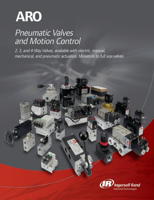
2 | Pneumatic ValvesDescriptionsSierra SeriesCompact 2-position, 4-way valves that are lightweight, yetdurable. 10mm, 15mm or 18mm wide. Body ported or sub-basemounted. Single and double solenoids available. M5 (10-32)and 1/8" ports.MaxAir Series2, 3 and 4-way air solenoid, pilot and hand lever valves featureexcellent flow in a compact, lightweight package.SERIES(Page 4, 26)(Page 16, 38, 46, 50, 69)Alpha SeriesHigh flow, 2-and-3-position, 4-way valves that are compact insize with many features. The family includes: Body Threaded,Stacking, Bar Manifold and Assembled Manifold. Single anddouble solenoids, or pilot actuators are available. 1/8", 1/4"and 3/8" ports.Cat SeriesSmall, 3-way solenoid valves. Perfect for small bore, singleacting cylinders and electric to air interfacing applications.Body ported for stand alone applications, stacking or basemanifold. Available as normally open or normally closed.1/8" and 1/4" ports.50 Series3-way and 4-way body ported valves. Six manual, mechanicaland pilot actuator styles available. 1/8" ports.E-Series3-way and 4-way body ported valves. Nine manual, mechanical,pilot and solenoid actuator styles available. 1/4" ports.ALPHATM(Page 32)50E(Page 20)C atSeries Valves(Page 42)Series ValvesSeries Valves(Page 52)K-SeriesManual, Pilot and Solenoid, heavy duty 4-way valves. Availableas body ported. Seven actuator styles available. Manual: 3/8"and 1/2" ports. Solenoid and Pilots: 3/8", 1/2", 3/4" and 1" ports.H-SeriesHigh flow 3-and-4-way function Poppet valves. Available insolenoid, pilot and bleed actuators. 1/4", 3/8" and 1/2" ports.Premair3-and-4-way direct acting solenoid valve. Rugged constructionand lightweight, stand alone and stacking. Available in 1/8" ports.KHSeries Valves(Page 58)Series Valves(Page 62)(Page 36)
Pneumatic Valves | 3AccessoriesAccessory Valves• 100 Series - 3-way N.C., miniature limit valves.• 200 Series - 3-way limit valve-ideal for sensing devices such ascylinders, slides and gates.• 400 Series - Heavy duty 3-way limit valves, 4 actuator arms available.200 Series Valve• 460 Series - 3-way palm button valves.• The 200, 400 and 460 are multipurpose valves, plumb N.O.,N.C., diverter, and selector.• In line and right angle flow controls, in line needle and check valves.460 Series ValveValve Accessories and Special Valves• Bleed valves: manual button and pilot operated.• Quick exhaust valves for enhancing cylinder speed.• One shot pulse valve to convert continuous air supply to amomentary output.Quick Exhaust Valve• Shuttle valves operate as a check when two inlets are required.• Micro switch converts pneumatic signal into an electric signal.• Exhaust mufflers, exhaust speed controls, breather vents.Exhaust MufflerPneumatic Logic Controls• Two-hand anti-tie-down unit for monitoring operators hands duringwork cycle.• Pneumatic pulse and delay timers for use in simple valve circuitry.• Pneumatic counters.2-Hand Anti-Tie Down
4 | Sierra 10 • Pneumatic ValvesFeaturesSierra TN Series Miniature Manifold Valvesare excellent choices for:Dispensing Applications Control SystemsConverting Applications Food ProcessingPackaging Applications Animation3-Way Valves Single Solenoid Normally Closed, Direct Acting Low Power Consumption Compact Space Saving Design Large Flow Capacity Cv 0.014-Way Valves Quick Response and Large Flow capacity High Reliability Compact size Single Solenoid, Double Solenoid, 2-Position, 3-Position Spring Centered Low Power ConsumptionOrdering4-Way Manifold, Double SolenoidModelNumber Description Voltage Watts/VAValves3-WayTN15M5S-012-H 3-Way Solenoid/Spring Return 12 VDC 1.0TN15M5S-024-H 3-Way Solenoid/Spring Return 24 VDC 0.6TN15M5S-120-H 3-Way Solenoid/Spring Return 110 VAC 1.44-WayTN1210S-012-H 4-Way Solenoid/Spring Return 12 VDC 1.0TN1210S-024-H 4-Way Solenoid/Spring Return 24 VDC 0.6TN1210S-120-H 4-Way Solenoid/Spring Return 110 VAC 1.6TN1210D-012-H 4-Way 2 Position Solenoid/Solenoid 12 VDC 1.0TN1210D-024-H 4-Way 2 Position Solenoid/Solenoid 24 VDC 0.6TN1210D-120-H 4-Way 2 Position Solenoid/Solenoid 110 VAC 1.6All Ports BlockedTN1310D-012-H 4-Way 3 Position Spring Centered 12 VDC 1.0TN1310D-024-H 4-Way 3 Position Spring Centered 24 VDC 0.6TN1310D-120-H 4-Way 3 Position Spring Centered 110 VAC 1.6Vertical Electrical Entry available: Consult FactoryModelModelNumber M5 Ports Number 10-32 NPT PortsManifold*3-Way4-WayTNM15-01 Single Station TNM14-02 2 StationsTNM15-02 2 Stations TNM14-04 4 StationsTNM15-03 3 Stations TNM14-06 6 StationsTNM15-04 4 Stations TNM14-08 8 StationsTNM15-05 5 Stations TNM14-10 10 StationsTNM15-06 6 StationsTNM15-07 7 StationsTNM15-08 8 StationsTNM15-09 9 StationsTNM15-10 10 StationsBlanking KitTNB14* Other manifolds available up to 16 stations. Consult factory.4-Way Manifold3-Way 2 station manifold4-Way 4 station manifoldBlanking Kit TNB14(4-way only)3-Way ManifoldVertical Electrical Entry available: Consult Factory
Sierra 10 • Pneumatic Valves | 5Performance Specifications3-Way4-WayBody Style Manifold Mount Manifold MountMedia Air AirTemperature Range 44-122 F (5-50 C) 44-122 F (5-50 C)Operating Pressure2-Position Single 0-100 PSIG (0-7 Bar) 20-100 PSIG (1.5-7 bar)2-Position Double N/A 15-100 PSIG (1-7 bar)3-Position N/A 30-100 PSIG (2-7 bar)Cv FactorResponse Time0.0110ms0.212msPower Consumption DC 1.0 W 12 VDC, .6W 24 VDC DC 1.0 W 12VDC, .6W 24 VDCLead EntryAC 1.4 WHorizontalAC 1.6 WHorizontalManual Override Non-Lock Push Push & LockLubrication None Required None RequiredConnection IP65 Rating IP65 RatingDimensional Data.413(10.5).496(12.6)10.32(M5X0.8).314(8).511(13)1.30(33).846(21.5)1.46(37.1)(4) M5X0.8.196(5) .196(5).393(10).984(25)1.46(37).452 .413(11.5) (10.5).129(2) (03.3).118(3.0)L1L2L2L1.413(10.3).590(15).157(4).551(14).177 (4-(45) thru)4.11(104.6).354(9)(6) NPT 1/8”LPLPLPLP2.21(56.3)1.52(38.6)1.12(28.5)10-32 (2-M5X.08).834(21.2)3.16(80.3)A BA BA BA B.606(15.4).629(16)4.45(113.1).610(15.5).925(23.5).610(15.5)2.12(54).413(10.5).28(7).413(10.5).28(7).334(8.5)L PL P3-Way ManifoldStations 2 3 4 5 6 7 8 9 10L1 1.31(33.5) 1.73 (44) 2.14 (54.5) 2.56 (65) 2.97 (75.5) 3.38 (86) 3.80 (96.5) 4.21 (107) 4.62 (117.5)L2 1.08 (27.5) 1.50 (38) 1.91 (48.5) 2.32 (59) 2.74 (69.5) 3.15 (80) 3.56 (90.5) 3.98 (101) 4.39 (111.5)4-Way ManifoldStations 2 4 6 8 10L1 1.51(38.5) 2.34 (59.5) 3.17 (80.5) 4.00 (101.5) 4.82 (122.5)L2 1.20 (30.5) 2.03 (51.5) 2.85 (72.5) 3.68 (93.5) 4.50 (114.5)
6 | Sierra 15 • Pneumatic ValvesFeaturesAt Last. A Miniature Valve with Maximum Range.Body-Ported:• 2-position single and double solenoid models.• Two wiring options: Lead Wire and Plug-In.• Available in 120V AC, 24V DC or 12V DC.• Body-Ported valves can be mounted on low profile manifoldto simplify installation when using multiple valves.Superior flow capacity, an unrivaled array of “realworld”design features and options, a valve bodythat is both ultra-compact and lightweight—yetexceptionally durable—this is Sierra 15, the miniature valve withthe maximum range.Base Mounted:• 2-position single and double solenoid models.• Standard 2-, 4-, 6-, 8-, 10-, 12- and 16 stations.• Stand-alone subbase (for 1-station) with M5 (10-32) or 1/8" NPT(F) ports.• Two wiring options: Lead Wire and Plug-In and three voltageoptions 120V AC, 24V DC or 12V DC.One-Touch Manual Valve Override (Standard)Mechanical valve override is nonlocking spring returnpush with tool.Wiring and Voltage OptionsLead-Wire Style: Valve lead wires come stripped andpreattached to the coil (NEMA 4). All models are availablein either 120V AC, 24V DC. 12V DC Available on plugin only.Ultra-Compact Valve DesignAt only 15 mm wide, Sierra 15 is the one compactvalve that’s going to fit your valve locationrequirements – with room to spare.Durable Body ConstructionSierra’s body features bar stockaluminum construction, producing alight weight, yet durable valve.Manifold OptionsManifolds are available in 2, 4, 6, 8, 10, 12 and 16-stationconfigurations. Sierra manifolds are available with 1/8"NPT(F) ports. Sierra Valves and Manifolds are soldseparately.Stand-alone sub-bases available in M5 (10-32) or 1/8"NPT, for use with manifold mount valves only.Performance SpecificationsPressure Range: 22 to 115 PSI (0.8 M pa)Shift Pressures: 22 PSI Single or Double-SolenoidFlow: 9 SCFM, .25 CvOperating Medium: Compressed AirLubrication: None RequiredCycle Rate:120 Cycles Per MinuteTemperature Rating: 0° to 122°F (-17° to 50°C)Signal Response Time 14 msRated Voltage: 120V AC, 24V DC and 12V DCCurrent Ratings: 120V AC = 16 mA in-rush; 11 mA holding 12V DC & 24V DC = 67 mAPower Consumption: 2.1/1.8 VA 1.9 WSierra Valves on SML51N-02 Low Profile Manifold
Sierra 15 Body Ported Ordering Information • Pneumatic Valves | 7Single Solenoid(Lead Wire)Double Solenoid(Plug-In Model)OrderingSierra Valve SizeCode DescriptionS5 15 mmNumber of CoilsCode DescriptionS Single Solenoid, Spring ReturnD Double SolenoidValve StyleCode DescriptionS Standard Solenoid OperatorLow Profile ManifoldS5 X S M X - 1SML51N – XXCoil Style/ VoltageCode DescriptionA Lead Wire, 120V ACB Lead Wire, 24V DCC Plug-In, 120V ACD Plug-In, 24V DCF Plug-In, 12V DCA, B NEMA 4 RatingC, D NEMA 2 Rating& FBody StyleCode DescriptionM M5 (10-32)ABR 1 P R 2Sierra Manifold:15mm valve low profilemanifold with 1/8" Supplyand Exhaust PortsNumber of StationsCode Description02 2 Stations04 4 Stations06 6 Stations08 8 StationsNOTE: Low Profile Manifolds are for use with Body Ported Valves only. One gasket and two screws are provided per station.Replacement CoilsPart Number Description119892-33 120 VAC Plug-In119892-39 24 VDC Plug-In119892-38 12 VDC Plug-InPart Number Description119893-33 120 VAC Lead Wire119893-39 24 VDC Lead Wire
8 | Sierra 15 • Pneumatic ValvesOrderingSingle Solenoid(Plug-In Model)Base-Mounted ValvesSierra Valve SizeCode Description5 15 mmNumber of CoilsCodeSDDescriptionSingle Solenoid, SpringReturnDouble SolenoidValve StyleCodeSS5 X X 9 X - 1DescriptionStandard Solenoid OperatorCoil Style/ VoltageCode DescriptionA Lead Wire, 120V ACB Lead Wire, 24V DCC Plug-In, 120V ACD Plug-In, 24V DCF Plug-In, 12V DCA, B NEMA 4 RatingC, D & F NEMA 2 RatingWhen raceway option is used, requires a119354 Single Solenoid or 119355 DoubleABBody StyleCode Description9 Base MountedR1PR2SubbasePort SizeManifold11936 XCode Description7 M5 Subbase (10/32" threads)8 1/8" SubbaseSierra Manifold:15mm valve with 1/8" PortsWiring ConfigurationCodeNDescriptionNormal ManifoldSMH51 X - XXSierra Valve on M5Stand-alone SubbaseNumber of StationsCode Description Code Description02 2 Stations 10 10 Stations04 4 Stations 12 12 Stations06 6 Stations 16 16 Stations08 8 StationsManifold Close-UpReplacement CoilsPart Number Description119892-33 120 VAC Plug-In119892-39 24 VDC Plug-In119892-38 12 VDC Plug-InPart Number Description119893-33 120 VAC Lead Wire119893-39 24 VDC Lead Wire
Sierra • Pneumatic Valves | 9
10 | Sierra • Pneumatic Valves
Sierra • Pneumatic Valves | 11Standard Manifold Dimensions.7501.97No. ofStations“A”2 2.323 (59)4 3.661 (91)6 5.000 (127)8 6.339 (161)10 7.678 (195)12 9.017 (229)14 10.356 (263)16 11.695 (297)Additional Valve Accessories119351 Blanking PlateGasketted metallic plate installs inminutes and caps off unusedmanifold ports. Order one plateper valve station.Ordering119375 ReplacementGasket/FastenerKit contains Valve Gasket, BlockGasket, Valve-to-Manifold Screw,Replacement Shut-Off Block toManifold Screw, ReplacementRaceway Screw and ReplacementManifold Blanking Plate.119376 Pipe Plug KitContains 3 (ea.) 1/8” pipe plugs.119350 “Sandwich” Shut Off BlockAllows a specific manifold valve to be removed without shutting down pressure to rest of the manifold.One Solenoid Valveneeds to be replacedduring set-up.Loosen the valve’sretaining screws andlift off valve.Removing the valve automaticallycauses the Shut-Off Block toclose the valve ports leading tothe manifold.Replacing the valveautomatically reopens theports and reenergizes thenew valve.119350 “Sandwich”Shut-off Block forManifold ValvesIMPORTANT: The Shut-off Block option is intended for machine setup convenience only. When performing routine maintenance on machinery, always observeproper lock-out/ tag-out procedures.
Sierra 18 • Pneumatic Valves | 13OrderingBody Style8 - 18mm ValveSeries1 - 1/8" NPTFValve TypeBody Ported2 - Two Position3 - Three Position Spring Centered(All Ports Blocked)7 - Three Position Spring Centered(Cylinder Ports Open to exhaust)A - Three Position Spring Centered(Cylinder Ports Pressurized)Manifold Mount9 - Two Position, Manifold Mount Valve(Order High Profile Manifold Separately)Low Profile Manifold & Blanking PlateModel DescriptionSML81N-02 2-Station ManifoldSML81N-04 4-Station ManifoldSML81N-06 6-Station ManifoldSML81N-08 8-Station ManifoldSML81N-10 10-Station ManifoldSML81N-16 16-Station Manifold114155 Blanking Plate114803 ReplacementGasket/Screw Kit(One Gasket &Two Screws)M 8 1 X X X - X X X - XOperatorSD - Double SolenoidSS - Solenoid/SpringCoil OptionsA - Standard Coil ACD - Standard Coil DCN - No CoilCoil Voltage000 - No Coil012 - 12 Volt DC024 - 24 Volt DC120 - 120 Volt ACConnector & CoilModel DescriptionCHL6-012 12 VDC molded cableconnector w/indicator light,39” leadsCHL6-024 24 VDC molded cable connectorw/ indicator light, 39” leadsCHL6-120 120 VAC molded cable connectorw/ indicator light, 39” leadsCHW6 16 mm molded cable connector, 39”leadsCSL6-012 12 VDC strain relief connectorw/ indicator lightCSL6-024 24 VDC strain relief connector,w/ indicator lightCSL6-120 120 VAC strain relief connector,w/ indicator lightCSN6 16 mm, strain relief connector114153-33 120 VAC, lead wire coil114153-38 12 VDC, lead wire coil114153-39 24 VDC, lead wire coil114138-33 120 VAC, standard coil114138-38 12 VDC, standard coil114138-39 24 VDC, standard coilCHL6-120CHW6CSN6High Profile Manifold & Blanking PlateModel DescriptionSMH81N-02 2-Station ManifoldSMH81N-04 4-Station ManifoldSMH81N-06 6-Station ManifoldSMH81N-08 8-Station ManifoldSMH81N-10 10-Station Manifold114808 Blanking Plate
.531 .5314.2914 | Sierra 18 • Pneumatic ValvesDimensional Data1.38.669.510.124 (2 PL).531.124 (2 PL).710M812SS-XXX-X5.98 (2-Position) 6.33(3-Position)M812SD-XXX-XM813SD-XXX-XM819SS-XXX-XM819SD-XXX-X
Sierra 18 • Pneumatic Valves | 151/4"NPT.9552.28Low Profile ManifoldA.79A B2-Station 2.24 1.854-Station 3.74 3.356-Station 5.24 4.848-Station 6.73 6.3410-Station 8.23 7.841/8"NPT31.8.18 Hole Dia.(4 places)18.6CB60.5C D2-Station 2.56 2.094-Station 4.06 3.596-Station 5.56 5.088-Station 7.05 6.5810-Station 8.55 8.08DHigh Profile ManifoldVisit our website at fluids.ingersollrand.com
16 | MaxAir • Pneumatic ValvesFeatures4-Way Air Solenoid & Pilot Valves 1/4", 3/8" & 1/2" NPT Ports• Ideal for packaging, material handling and airmotor applications• Ideal for double acting pneumatic cylinders• Compact size with excellent flow capacity• Single and double solenoid or pilot models• Three voltages available 120 VAC,12 and 24 VDC• Lightweight aluminum bodies andBuna-N seals are standard3-Position SpoolFunction ProvidesWider ApplicationFlexibility:MaxAir offers 3-position spoolconfiguration with all portsblocked in center.• Manifold mounting available, blanking platesprovided for future expansion• Max/Air valves use Alpha style 22mm coil• 1/4" = 26 mm Body Size• 3/8" = 30 mm Body Size• 1/2" = 34 mm Body SizeSolenoid Coils and Connectors Provide Quick,Clean Connections:Coils are Class F rated for 100% duty cycle applications at 122° F ( 50° C).AC or DC coils can be interchanged on the same solenoid stem. EachSolenoid connector acts as its own junction box, with molded connectorsand gaskets to protect electrical connections. Design meets NEMA-4specifications.One - Touch Manual Override(Standard):MaxAir contains a mechanical valve overridethat can be adjusted to a locking (push ‘ntwist) position or non-locking function.OrderingValves are Body-Threaded and can beManifold - Mounted:MaxAir is a body - threaded valve that can be directlyplumbed or manifold - mounted. Where there’s a need formultiple valves in tight spots, especially in machine designoperations. Manifolds Available in 2, 4, 6, 8, 10, and 12Station Configurations.M - 2 1 2 - S S * - 1 2 0 - AValve Type* Body Style Port Size Actuator/Return Coil Voltage Coil Options2=2 Position 1=4 Way 2=1/4" NPT SS=Single Solenoid/Spring 000=No Coil N=No Coil3=3 Position Side Ported 3=3/8" NPT SD=Double Solenoid 012=12 VDC A=ACAll Ports Blocked 4=1/2" NPT PS=Pilot / Spring* 024=24VDC D=DCSpring Centered (Sol. & Pilot Only) PD=Pilot / Double* 120=120VAC* Model number ends here on pilot activated valves.Performance SpecificationsC v (Solenoid) (Pilot) 1/4 = .70, 3/8 = 1.65, 1/2 = 4.32SCFM 1/4"= 26, 3/8"=61, 1/2"=150Port Size NPT 1/4", 3/8", 1/2"Operating Medium Non-Lubricated or Lubricated AirPres. Range (Solenoid) 45 - 115 PSIPres. Range (Pilot) 45 - 140 PSIDuty Cycle 100%Temp. Range 15° to 122° F (-10° to 50° C)Minimum Shift Pres. 2 position single pilot, single solenoid,spring return - 45 PSI2 position double pilot - 45 PSI2 position double solenoid-20 PSI3 position double solenoid, double pilot,spring centered - 45 PSI
MaxAir • Pneumatic Valves | 17OrderingManifoldNo. ofStations1/4" NPTPorts3/8" NPTPorts1/2" NPTPorts2 M26M02-02 M30M03-02 M34M04-024 M26M02-04 M30M03-04 M34M04-046 M26M02-06 M30M03-06 M34M04-068 M26M02-08 M30M03-08 M34M04-0810 M26M02-10 M30M03-10 M34M04-10Manifold KitsKits include: manifold,seals and valveattaching hardware22mm ConnectorModel DescriptionCHW Straight connector withcable (36") located on topCBWStraight connector withcable (36") located on backCHL-XXX Straight connector (36")with indicator light locatedon back.CSNCSL-XXXStrain relief, withoutindicator light or cable.Strain relief, with indicator lightlocated on the back.CHWCBWCHL-XXXCDN1/2" conduit without light or leadwireCSN, CSL-XXXDimensional DataCDW1/2" conduit without light,18" lead wireACDL-XXX1/2" conduit with light,18" lead wireCDN, CDWCDL-XXXXCVoltage (-XXX)012 = 12 VDC/VAC 024 = 24 VDC/VAC 120 = 120 VDC/VAC.169 Hole Dia.(4 places)BBlanking Plate KitM26MB Fits 1/4" (26 mm) manifoldsM30MB Fits 3/8" (30 mm) manifoldsM34MB Fits 1/2" (34 mm) manifolds1/4”1/4" 3/8" 1/2"Stations A B C A B C A B C2 3.189 2.638 0.866 3.661 3.031 1.063 4.134 3.346 1.1814 5.315 4.764 0.866 6.101 5.471 1.063 6.890 6.102 1.1816 7.441 6.890 0.866 8.541 7.911 1.063 9.646 8.858 1.1818 9.567 9.016 0.866 10.981 10.351 1.063 12.402 11.614 1.18110 11.693 11.142 0.866 13.421 12.791 1.063 15.158 14.370 1.1813/8” 1/2”
18 | MaxAir • Pneumatic ValvesDimensional DataSolenoidM212SSM214SSPilotM213SSM212PSM214PSM213PS
MaxAir • Pneumatic Valves | 19Dimensional DataSolenoidPilotM212SDM312SDM213SDM313SDM214SDM314SDM212PDM312PDM213PDM313PDM214PDM314PD
20 | Alpha • Pneumatic ValvesFeaturesBody Ported ValvesCompact, space saving design.Perfect for stand alone andremote valve applications.Ports have ISOidentification. Sizesinclude 1/8", 1/4" and3/8" NPT .Subbase ValvesReplace valves easily! Simply remove three screws, lift offvalve and replace. Math made simple! Add or subtractmanifolds by removing an end plate and changing the valvestack as needed. No tie rodsto make changing manifoldlengths difficult. Port sizesof 1/8", 1/4", 3/8" and1/2" with ISO portidentifications. SubbaseValves use the sameelectrical coils and connectors as theALPHA Body Ported Valve. Both End Plates canbe used for common supplies and exhaust in highflow applications.Stacking ValvesThe lowest cost method of gangingvalves, because it eliminates themanifold. Flip out design. Loosenthe end plate cap screws to swingthe valve up and out. No need todisassemble entire stack to replaceone valve. Bodies stack on 1" centers.Circuits can be designed and mounted ina compact area. When stacked, ALPHA becomes a 4-way, 4-portedvalve. 3/8" common end plate ports with 1/8" or 1/4" working ports inthe valve body. .“Thin” Manifold ValvesThin, 1" width means more valves in lessspace. Faster assembly than stacking stylevalves. 2, 4, 6, 8, and 10 stationmanifolds are available. Use optionalblanking plates for odd-numberedstations. 1/4" (NPT) models, with 3/8"supply or exhaust ports. Speed controlsinstall directly into manifold, cuttingset-up time.Versatile Design• Available in Body Ported, Subbase,Stacking and “Thin” configurations.• Alpha can be ordered as a two-position orthree-position valve.• 5-Year Warranty.• Valve Body, End Plate amd- Manifoldmaterial is zinc.Superb Performance• ALPHA’s bonded, precision ground spoolresists wear & provides excellent shiftresponse.• Large air passages result in high flowcharacteristics. Listings detail Cv factorand maximum flow rates.Numerous Control Options• Control the valve one of five ways:Solenoid/Spring, Solenoid/Solenoid,Solenoid/Pilot, Pilot/Spring or Pilot/Pilot .• External solenoid supply allows operation forvacuum service and low pressureapplications. (Use kit No. 119306)• Coils are UL and CSA Listed(Files: UL #MH13513; CSA #LR51090).Performance SpecificationsPressure Range:Operating Medium:Lubrication:Filtration:Cycle Rate:Temperature Rating:Shift Pressures:Vacuum to 150 psi (10.2 bar)Flow:Compressed Air or inert gasBody PortedNone Required40 Micron recommended600 Cycles Per Minute0° to 180°F (-17° to 82°C)50 psi (3.4 bar) 2-Position Single Solenoid orSingle Pilot, Spring Return.Subbase Valves:20 psi (1.4 bar) 2-position double pilot or doublesolenoid.60 psi (4.0 bar) 3-Position Double Solenoid orDouble Pilot, Spring Centered.Stacking Valves:Signal Response Time:Double Pilot Actuator: 14 msDouble Solenoid:20 msSingle Pilot (Pilot On) 19 msSingle Pilot (Pilot Off) 26 msSingle Solenoid (Energized) 22 msSingle Solenoid (De-energized) 27 ms“Thin” Valves:2-position 1/8" Ports = .9 Cv, 30 SCFM2-position 1/4" Ports = 1.5 Cv, 50 SCFM2-position 3/8" Ports = 1.7 Cv, 61 SCFM3-position 1/8" Ports = .8 Cv, 27 SCFM3-position 1/4" Ports = 1.4 Cv, 45 SCFM3-position 3/8" Ports = 1.7 Cv, 61 SCFM1/8" Ports = 1.3Cv, 43 SCFM1/4" Ports = 1.6 Cv, 54 SCFM3/8" Ports = 1.6 Cv, 54 SCFM1/2" Ports = 1.75 Cv, 57 SCFM2-position 1/8" Ports = 1.32 Cv, 43 SCFM2-position 1/4" Ports = 1.9 Cv, 63 SCFM3-position 1/8" Ports = 1.2 Cv, 39 SCFM3-position 1/4" Ports = 1.7 Cv, 57 SCFM1/4" Ports = 1.2 Cv, 39 SCFM
Alpha • Pneumatic Valves | 21OrderingAlpha SeriesValve, Spool TypeCode Description2 2-Position, Urethane3 3-Position, Urethane8 3-Position, Viton(3 & 8 are Spring Centered, all portsblocked in neutral. Available only withPD or SD Actuators)4 2-Position, Viton7 3-Position, Urethane9 3-Position, Viton(7 & 9 are Spring Centered, inlet portsblocked (cylinder ports open) in neutral.Available only with PD or SD Actuators)Valve Body StylesCode Description1 4-Way, Body Ported Valves2 4-Way, Stacking ValvesOrder End Plates from menu on Page 22.Order Mounting Brackets from Page 22.3 4-Way, Subbase Mounted ValvesOrder Subbase Manifolds from menuon Page 23.4 4-Way, Alpha Thin ValvesOrder Alpha Thin Manifolds & Speed ControlKits from menus on Page 23.A X X XXX - XXX - XPort SizeActuator/Return*Current TypeCode DescriptionA ACD DCN No Coil*L Low Watt*(DC Only, 115 PSI Max.)Coil VoltageLeave Blank if ordering Pilot ValvesCode Description Code Description000 No coil 024 24V AC/DC005 5V DC 120 120V AC012 12V AC/DC 240 240V ACCode Description*PS Pilot/Spring*PD Pilot/PilotSS Solenoid/SpringSD Solenoid/SolenoidSP Solenoid/Pilot*Numbering ends here if a non-solenoid (PSor PD) valve is being selected.Code Description1 1/8” NPTF (#1 & #2 available on Body Ported2 1/4” NPTF or on Stacking Valves)3 3/8” NPTF (#3 available on Body Ported Valves only)9 NONE (#9 used on Subbase or Alpha Thin Valves)If coil option A, Dor L is selected, acoil connectormust be ordered.See Pg. 79 forcoil & connectorinformation. (LowWatt coils workonly on valveswith low wattoption)Ordering ExamplesBody Ported Valve: A212SS-120-A “Thin” Valve & Manifold: A449PS“2” 2-Position Valve, Urethane Spool “4” 2-Position Valve, Viton Spool“1” 4-Way Body Ported Valve “4” 4-Way Alpha “Thin” Valve“2” 1/4" NPTF Ports “9” 9 No NPTF Ports“SS” Actuator-Solenoid, Return-Spring “PS” Actuator-Pilot, Return-Spring“120-A” 120 Volt Coil, AC Current “Thin” Manifold: 118605-4“11860X-X” Basic Manifold“5” 1/4" NPT Ports“-4” 4-StationsManifold information on Page 23.119306 External SupplyConversion Kit, Page 22.Use when supplypressure is under 50 PSIor vacuum is used.4-Way, 2-Position4-Way, 3-Position, allports blocked in neutral4-Way, 3-Position,cylinder ports open,inlet port blocked
22 | Alpha • Pneumatic ValvesAccessories for Alpha Stacking ValvesEnd Plates and Isolator PlatesMKN One MKN Kit is required to stack 1-to-6 Valves withoutIsolator Plates. Each contains 2 End Plates, 2 Cap Screwsand 1 Gasket.MKP One MKP Kit is required to stack 7-to-12 Valves withoutIsolator Plates, or 1-to-12 Valves with an Isolator Plate.Each contains 2 End Plates, 2 Cap Screws and 1 Gasket.PTN Isolator Plate. Blocks Supply and Exhaust Ports. GasketIncluded.PEN Isolator Plate. Blocks Exhaust Ports. Gasket Included.PPN Isolator Plate. Blocks Supply Ports. Gasket Included.Mounting BracketsKits include both Brackets and hardware to mount valve stacks to the brackets.116710 Tie Bold Kit116807 Long L - 7" long116808 Short L - 3.75" long116809 Tall Z - 6" high117987 Short Z - 3" highDimensional DataMounting BracketsValveStacking End PlateCap Screw116808 Short LIsolator Plate(when needed)GasketsStacking PinTypical Stacking Valve Assembly116809 Tall Z2.501.25.875.687.344 (2PL).306 .472R .172 TYP.375.190R. 172TYP.983.251.28.4721.544.335.672R.375R.3751.522.417.817.4171.28“L” Brackets #116807 and 116808Tall “L” 7.0Short “L” 3.8151.08 1.08.344 2PL“Z” Brackets #116809 and 117987Tall “Z” 6.0Short “Z” 3.0.190
Alpha • Pneumatic Valves | 23AccessoriesBreather Vent, External Supply Plug Kit116464 Solenoid Breather Vent 10-32 Thread Size.119306 External Solenoid Supply Plug KitChanges ALPHA valves from internal to externalsolenoid air source.Step #1: Remove all air supply sources, remove sealingplug. Figure 1.Step #2: Install separator plug by threading plug into valvebody with a flat-head screwdriver.See Figure 2.Step #3: Connect the external pilot air supply to the valvewith an 1/8" NPT connector.Alpha “Thin” ValvesAlpha Thin ManifoldsPort SizeCode Description5 1/4” NPT11860X - XNumber of StationsCode Description2 2 Station4 4 Station6 6 Station8 8 Station10 10 StationAlpha Thin Speed ControlsControl speed directly from the manifold. Kits allow you tocontrol only the cylinder direction needed.119230 Kit controls Port 2 exhausting to Port 3.119231 Kit controls Port 4 exhausting to Port 5.118618 Includes both 119230 and 119231 control kits.118612 Station blanking kit.Subbase ValvesManifold & End Plate Kits• Manifold Kits are required when ordering Sub-base valves.• One End Plate Kit is needed for each valve stack.• Manifold Kits include the Manifold,one Gasket and two Screws.• End Plate Kits include two End Plates,one Gasket and two Screws.Port Size Manifold Kit End Plate Kit1/8" 115422-1 116904-11/4" 115455-1 116916-13/8" 116862-1 116917-11/2" 116899-1 116926-1SealingPlug3/16" Allen Wrench Flat-Head ScrewdriverSeparator PlugCover PlateValve BodyFigure 1 Figure 211860X-X ALPHA ThinManifold Stack118618 Speed Control KitSubbase Valve Manifolds &End PlatesThreadM4-.7
4124 | Alpha • Pneumatic ValvesDimensional Data Dimensions given in Inches and (Millimeters)1/8" and 1/4" Body Ported Valves2 15/16(74.6)3 31/32(100.8)1 15/32(37.3)3 1/4(82.6)1 13/16(46)Mounting Hole for No 10 Screw, 3PL“4” PORT(CYL)2 15/16(74.1)7/822.21/212.71/212.77/8(22.2)1 15/32(37.3)“2” Port (CYL)Pilot Port 2PL 1/8”NPTF1 13/16(46)3/419.131/321 1/2 (38.1)1 15/1649.27/8(22.2)1/2(12.7)13/16(20.6)5 Port Exhaust1 Port Inlet3 Port Exhaust57/16” (11.1)Mounting Hole for No1 10 Screw, 3PL33/8" Body Ported Valves4 Port (Cyl)Mounting HolePilot Port, 2PL,1/8” NPTF2 15/16(74.6)1 15/32’(37.3)1 3/16(30.1)27/8(22.2)2 Port (Cyl)13/16 (20.7)1/2 (13.0)1 7/32(31.7)2 7/16(56.0)2 1/32(56.0)3 5/8(92.2)33 31/32(100.6)3(75.8)1 1/2(37.9)5”1” Port (INLET)21/32(21.4) 1/2” (12.7)“5” Port (EXH)“3” Port (EXH)11/32(26.2)17/32(30.9)2 7/16(6.19)5 1 324Stacking ValvesMounting Hole, 1/4” Screw1 X (NO. OF VALVES) + 1 1/2(25.4)(38.1)12/2(12.7)1 X (NO. OF VALVES) + 1(25.4) (25.4)1(25.4)1(25.4)7/8(22.2)MTG SLOT FOR5/16 SCREW1 21/321 5/16 (42.1)(33.3)3 7/8(98.4)2 7/16(61.9)12/2(12.7)2 Port (Cyl.)4 Port (Cyl.)External Solenoid Supply1/8” NPTFPilot Ports1/8” NPTF7/8(22.2)INLET PORT3/8 NPTFEXHAUST PORT3/8 NPTF1 5/32(29.4)1 25/32(45.2)2 7/16(61.9)3 1/4(82.6)3 31/32(100.8)17/32(13.5)
Alpha • Pneumatic Valves | 25Dimensional DataSubbase Valves with 1/8" or 1/4" Cylinder Ports Dimensions given in Inches and (Millimeters)“3” Exhaust Port“5” Exhaust Port5.183.76“1”Inlet Port1.12.23.07MTG HOLE .281 (2PL).532.0.94“2” Port (Cyl.)“4” Port (Cyl.)1.87MTG HOLE .281 (2PL)4.11Subbase Valves with 3/8" or 1/2" Cylinder Ports“5” Exhaust Port“3” Exhaust Port5.544.122.23“1” Inlet PortMTG. HOLE.281 (2 PL.)1.262.52.882.51.26“2” Port (Cyl.)“4” Port (Cyl.)3.694.73Thin Manifolds with 3/8" or 1/4" Cylinder Ports5.664.13.284444MTG. HOLE.281 DIA.(4 PL.).28NO. OFSTATIONS A2 3.574 5.576 7.578 9.5710 11.57.19.28.66 MAX(OPTIONAL SPEEDCONTROL).991.912.824.03.44.951.251.511.00221.0TYPA22CYLINDER PORT.441.58 2.01
26 | 10mm Plug and Play • Pneumatic ValvesFeatures• Push-In Fitting Standard 5/32" , 1/4" inlet• High speed responsiveness and flow• Less than 12ms response time• Low power consumption• Compact and High Flow Rate• Plug In ValveNo wiring needed for installation• Modular Type Manifold• Each base is installed individually, so adding orremoving another base is simple.• Wiring MethodUsage of D-Sub connector, or Flat Cable connector,Substitute the D-Sub connector and Flat Cableconnector with ease• SafetyRoHS, UL, (In process of receiving CE mark.)• Easy to add SUP/EXH BlocksThere is no limit to the addition of SUP/EXH BlocksIt can be applied for dual pressure & back pressure applications.Performance SpecificationsOperating Pressures2-Position Single 21.8 to 101.5 p.s.i. (1.5 -7.0 bar)2-Position Double 14.5 to 101.5 p.s.i. (1.0 -7.0 bar)3-Position Double 29.0 to 101.5 p.s.i.(2.0 -7.0 bar)Operating Medium Compressed Air onlyTemperature 23° to 122° F (-5° tp 50° C)Coil Voltage 12, 24 VDC (± 10%)Power Consumption 085 WattsFlow0.22 Cv (4.0mmÇ)OrderingValve Valve on ValveAction Manifold Only4-Way 2 PositionSingle Solenoid 12 VDC TP12C4S-012-M TP12C4S-012-VSingle Solenoid 24 VDC TP12C4S-024-M TP12C4S-024-VDouble Solenoid 12 VDC TP12C4D-012-M TP12C4D-012-VDouble Solenoid 24 VDC TP12C4D-024-M TP12C4D-024-V4-Way 3 Position (all ports blocked)Double Solenoid 12 VDC TP13C4D-012-M TP13C4D-012-VDouble Solenoid 24 VDC TP13C4D-024-D TP13C4D-024-VManifold KitValve on Manifold114829 25 Pin Manifold Kit114836 26 Pin Manifold Kit114840 Supply/Exh Block114839 Din RailValve OnlyManifold Kit includes: 2-End Caps, 1-Supply/Exh block and 1-Din Rail (10 station)
10mm Plug and Play • Pneumatic Valves | 27Assembly Instructions1 End Plate2 Supply Exhaust Block3 Base4 Valve5 End Plate6 Locking Clip7 DIN Rail8 DIN Rail Screw9 “P” Port10 “R” Port11 “B” Port12 “A” Port5432169810117121. Before assemble, check for proper alignment of five “O”rings and (7) gasket.2. The (8) metal locking clip should be fully extended outbefore assembling.3. Position the (4) valves in the desired location in thestack. Align pins with sockets and push together. Slidethe (8) metal locking clip into place to lock the 2 unitstogether. Continue this procedure until all valvemanifolds have been connected. Manifold KitAttachment includes: two (1 and 6) end plates, (2)supply / exhaust block and (9) 1 - 10 DIN rail.4. Attach the (2) supply / exhaust block to the end of thestack and lock into place using the (8) metal lockingclip.5. Align the (1) end plate to the (2) supply / exhaust blockand lock into place using the (8) metal locking clip.6. Align the (6) end plate to the opposite end and lock intoplace using the (8) metal locking clip.7. Slide the (9) DIN rail onto the underside of the valvestack into the desired location. Tighten one (10) screwon top of each end plate. NOTE: (9) DIN rails may becut to size.To replace a (4) valve unit without disturbing the valvestack: Loosen and remove two (5) screws located on top ofvalve. Pull up on (4) valve to remove. Align the electricalconnection on the end of the valve with the manifold socket.Align and tighten (4) screws.NOTE: Ten (4) valves per stack maximum.The (8) metal locking clip must be extended out beforeassembly to prevent bending of clip.Voltages cannot be mixed on the valve stack
28 | 10mm Plug and Play • Pneumatic ValvesValve Circuits1. Common2. Solenoid “A”3. Solenoid “B”4. 1st Station5. 2nd Station6. 3rd Station7. 11th Station8. 12th StationManifold Electrical Arrangement
10mm Plug and Play • Pneumatic Valves | 29Dimensional Data25 Pin Sub-D ConnectorL3, L4 Sup/Exh Block: 0.65 (16.5 ) x n
30 | 10mm Plug and Play • Pneumatic ValvesDimensional Data26 Pin Flat Cable Connector
Notes | 31
32 | Cat Series • Pneumatic ValvesFeaturesValve Performance Features• CAT Series Valves are available as single station units, barmanifold or assembled as a stack.• CAT Series valves are suitable for air or inert gas.• Plugging the exhaust port allows single station valves to beplumbed as 2-way valves. See page 34 to order the optionalexhaust port plug.• CAT Series valves are available with a variety of coil options.See Pg. 80.• Class F coils are rated for 100% duty cycle.CAT Series Valve Features and Benefits• Quick change coil can be easily interchanged or replaced.Simply remove the top nut, slide off the coil and replace it with anew coil.• The coil accepts DIN-style connectors, or automotive spade typeconnections. This helps reduce installation time and provides asecure electrical hook-up. See page 80.• When mounted individually, the coil can be rotated to face oneof four ways. As a stack, the coils can be mounted in twodirections.• Coils are UL-listed and comply with CSA standards. UL file#MH13513, CSA File #LR51090. NEMA 4 option available.Performance SpecificationsPressure Range:0 to 115 PSI Low WattPressure Range:0 to 150 PSI (10.4 bar)Temperature Rating: 0° to 122°F (-17° to 50°C)Flow:1/8" Individual, Bar Manifold and Stacking Valves:CAT33P: Cv = .062 (2.2 SCFM), Seat Orifice .051, Stem .070CAT33S: Cv = .048 (1.8 SCFM), Seat Orifice .051, Stem .070CAT44P: Cv = .056 (2.0 SCFM), Seat Orifice .039, Stem .051CATXXB: Cv = .062 (2.2 SCFM), Seat Orifice .051, Stem .070Operating Medium: Compressed AirResponse Time:5 - 9 msSingle CAT Series ValveTwo Valve CAT Series StackHigh Flow Cat ValveSix-Station Cat ValveBar ManifoldPerformance Data, Ordering Menus and Dimensional Data for High-FlowCAT Valves are found on page 34.
Cat Series • Pneumatic Valves | 33Ordering22221/8" Individual and Stacking ValvesModel Number: Port Size Valve Function Body StyleCAT33P-XXX-X 1/8” Non-Passing PortedCAT33S-XXX-X 1/8” Non-Passing StackableCAT44P-XXX-X 1/8” Passing PortedCoil OptionsCode Voltage Current Code Voltage Current000-N Valve with No Coil 024-D 24 Volt DC005-D 5 Volt DC 120-A 120 Volt AC012-A 12 Volt AC 240-A 240 Volt AC012-D 12 Volt DC *005-L 5 Volt Low Watt DC024-A 24 Volt AC *012-L 12 Volt Low Watt DC*024-L 24 Volt Low Watt DC32321113Normally Non-PassingIf coil option A or D is selected,a coil connector must beordered. See Pg. 79 for coil &connector information.322311To stack CAT Series valves, tierodmounting 1 3 kits are required.1 3Order kits separately from themenu below.32311Normally Passing* Available on CAT33P-XXX-L & CAT33S-XXX-L only.23 123 121 3AccessoriesExhaust PlugStacking Tie-Rod Kits59632-1 (10-32 Thread) 116345-2 2 Valve StackPlugs exhaust port to convert normally 116345-3 3 Valve Stacknon-passing 3-way valve to 2-way. 116345-4 4 Valve StackNOTE: To make a normally passing 116345-5 5 Valve Stack3-way valve to a 2-way valve requires 116345-6 6 Valve Stacka DC plug.Tie-Rod Kits include tie rods,nuts, o-rings and a plug.CAT Series Valve Stackand116345-X Stacking KitDimensional Data Dimensions given in Inches and (Millimeters)CAT44P CAT33P CAT33SBody Ported, Body Ported StackingNormally Passing Normally Non-Passing Normally Non Passing1/8” NPTF#10-32 Thread#10-32 Thread.35(19.1)3.12(79.4).475(12.1)2.43(61.9).725(18.4).451(11.5)2.68(68.2).87(22.2)1.62 (41.3)1/8 NPTFPorts (2)1.62 (41.3).87(22.2) 1/8 NPTFPorts (2).875(22.2)1.625(41.3).141(3.6).407(10.3)1/8 NPTFPorts (2).391(9.9)1.0(25.4).391(9.9)1.0(25.4).594(15.1).875(22.2)#8-32 Mtg Holes (2).594(15.1).875(22.2).14(3.6)#8-32 Mtg Holes (2).594(15.1).875(22.2).14(3.6)#8-32 Mtg Holes (2).394(10).391(9.9)1.0(25.4)
34 | Cat Series • Pneumatic ValvesHigh Flow Cat ValveModel Number: Port Size Valve Function Body StyleCAT66P-XXX-X* 1/4" Normally Closed PortedCAT77S-XXX-X* 1/4" Normally Closed StackingCAT88P-XXX-X* 1/4" Normally Open Ported* Coil Voltage012-D 12 Volt DC120-A 120 Volt AC024-D 24 Volt DC000-N No Coil*012-L Low Watt DC*024-L Low Watt DC*Available on normallyclosed valves only.231High Flow Cat Valve231231231Performance SpecificationsPressure Range:Temperature Rating:Operating Medium:High-Flow Valves:0 to 150 PSI0° to 122° FCompressed AirCAT66P: Cv = .2 (6.9 SCFM)CAT77S: Cv = .2 (6.9 SCFM)CAT88P: Cv = .2 (6.9 SCFM)232113Normally Non-Passing2231To stack CAT Series valves, tierodmounting 1 3 kits are required.1 3Order kits separately from themenu below.2321Normally Passing232113Dimensional DataAccessoriesHigh Flow Cat Valve.3941.287#10 - 32Internal THD3.547(4.137 -N.O. Model).251.000#10 - 32 x .250DP Mounting Holes1/4-18 NPTPortsHigh-Flow Tie-Rod KitsStacking Tie-Rod Kits119698-2 (2 Stations)119698-3 (3 Stations)119698-4 (4 Stations)119698-5 (5 Stations)119698-6 (6 Stations)119698-7 (7 Stations)ConnectorCDW-30CSN-30CHW-30119690-XX30-mm connector with wire.30-mm connector, strain relief.30-mm connector, molded cable.See Page 79 for Coil information.1.0002.1521.5001/4-18 NPT Ports1.250
Cat Series • Pneumatic Valves | 35OrderingCat Valve Bar ManifoldC A T X X B - X X X - XNo. of Stations02 1003 1104 1205 1306 1407 1508 1609Coil OptionsCode Voltage Current Code Voltage Current000-N Valve with No Coil 240-A 240 Volt AC005-D 5 Volt DC 005-L 5 Volt Low Watt DC012-A 12 Volt AC 012-L 12 Volt Low Watt DC012-D 12 Volt DC 024-L 24 Volt Low Watt DC024-A 24 Volt AC024-D 24 Volt DC120-A 120 Volt AC120-D 120 Volt DCSee Page 79 for Connectorsand other Coil options.Dimensional Data Dimensions given in Inches and (Millimeters)Cat Valve Bar Manifold1/8 - 27 NPTFInlet Ports.4511.609.4073.275Six-Station Cat ValveBar Manifold.877 .725.5001.0001.000 BetweenStations.190 Mtg Holes1/8 - 27 NPTFPorts
36 | Cat Series • Pneumatic ValvesMiniature 3-Way and 4-Way ValvesOrdering Information:ModelDescriptionP114400114806END PLATE FOR 3-WAY OR 4-WAY VALVE STACKMOUNTING BRACKET FOR INLINE VALVES114807 ISOLATOR PLUG KIT FOR STACKING VALVESCSN-MICRO CONNECTOR, STRAIN RELIEFP251SS-012-D 3-WAY BODY PORTED, LEAD WIRE, 12 DCP251SS-012-E 3-WAY BODY PORTED, PLUG-IN, 12 DCP251SS-024-D 3-WAY BODY PORTED, LEAD WIRE, 24 DCP251SS-024-E 3-WAY BODY PORTED, PLUG-IN, 24 DCP251SS-120-A 3-WAY BODY PORTED, LEAD WIRE, 120 ACP251SS-120-B 3-WAY BODY PORTED, PLUG-IN, 120 ACP261SS-012-D 3-WAY STACKING, LEAD WIRE, 12 DCP261SS-012-E 3-WAY STACKING, PLUG-IN, 12 DCP261SS-024-D 3-WAY STACKING, LEAD WIRE, 24 DCP261SS-024-E 3-WAY STACKING, PLUG-IN, 24 DCP261SS-120-A 3-WAY STACKING, LEAD WIRE, 120 ACP261SS-120-B 3-WAY STACKING, PLUG-IN, 120 ACP211SS-012-D 4-WAY BODY PORTED, LEAD WIRE, 12 DCP211SS-012-E 4-WAY BODY PORTED, PLUG-IN, 12 DCP211SS-024-D 4-WAY BODY PORTED, LEAD WIRE, 24 DCP211SS-024-E 4-WAY BODY PORTED, PLUG-IN, 24 DCP211SS-120-A 4-WAY BODY PORTED, LEAD WIRE, 120 ACP211SS-120-B 4-WAY BODY PORTED, PLUG-IN, 120 ACP211SC-012-D 4-WAY BODY PORTED W/SPEED CONTROL, LEAD WIRE, 12 DCP211SC-012-E 4-WAY BODY PORTED W/SPEED CONTROL, PLUG-IN, 12 DCP211SC-024-D 4-WAY BODY PORTED W/SPEED CONTROL, LEAD WIRE, 24 DCP211SC-024-E 4-WAY BODY PORTED W/SPEED CONTROL, PLUG-IN, 24 DCP211SC-120-A 4-WAY BODY PORTED W/SPEED CONTROL, LEAD WIRE, 120 ACP211SC-120-B 4-WAY BODY PORTED W/SPEED CONTROL, PLUG-IN, 120 ACP221SS-012-D 4-WAY STACKING, LEAD WIRE, 12 DCP221SS-012-E 4-WAY STACKING, PLUG-IN, 12 DCP221SS-024-D 4-WAY STACKING, LEAD WIRE, 24 DCP221SS-024-E 4-WAY STACKING, PLUG-IN, 24 DCP221SS-120-A 4-WAY STACKING, LEAD WIRE, 120 ACP221SS-120-B 4-WAY STACKING, PLUG-IN, 120 ACP221SC-012-D 4-WAY STACKING W/SPEED CONTROL, LEAD WIRE, 12 DCP221SC-012-E 4-WAY STACKING W/SPEED CONTROL, PLUG-IN, 12 DCP221SC-024-D 4-WAY STACKING W/SPEED CONTROL, LEAD WIRE, 24 DCP221SC-024-E 4-WAY STACKING W/SPEED CONTROL, PLUG-IN, 24 DCP221SC-120-A 4-WAY STACKING W/SPEED CONTROL, LEAD WIRE, 120 ACP221SC-120-B 4-WAY STACKING W/SPEED CONTROL, PLUG-IN, 120 AC4-Way Body Ported3-Way Body Ported4-Way Body Portedwith Speed Controls3-Way and 4-Way Stacking Valves114806 Mounting BracketKit is designed for use with both 3-Wayand 4-Way valves. Kit consists of abracket, two #6-32 screws, and twonuts.P114400 End Plate KitKit consists of two end plates, twoo-rings, and two bolts. One kit requiredfor each valve stack. Can be used for3-Way or 4-Way valves, or anycombination of valves.CSN-MICRO ConnectorPlug-in DIN type connector conformsto Industrial Micro Type C.Order separately.114807 Isolator Plug KitKit consists of two plugs. Plugs can beused on stacking valves to convert4-ways to 3-ways, or 3-ways to 2-ways.Also can be used to provide multiplepressures to a valve stack.
Premair • Pneumatic Valves | 373-Way Valves• Quick Response• Direct Acting/Single Solenoid• Non-Locking Manual Override• Continuous Duty Coil• 1/8" NPT• 2-Position/Spring Return• Can be used as a Diverteror Selector Valve4-Way Valves• Quick Response• Can be used in a variety of2-, 3-, and 4-Way functions• Direct Acting/Single Solenoid• Non-Locking Manual Override• Continuous duty Coil• 1/8" NPT• 2-Position/Spring Return• Optional Built-InDual Flow ControlsDimensional Data4-Way Body PortedPerformance Specifications:Port Size-NPT1/8” NPTMediaAir or Inert GasOperating Pressure3-Way, 0 to 125 PSI4-Way, Vac to 125 PSIAmbient Temperature Range 32 to 125 F (0 to 50 C)Cv Factor .144Coil Rated Voltage120VAC (50/60Hz); 12, 24 VDCAllowable Voltage Fluctuation + or - 10% of Rated VoltageCoil Insulation TypeClass B Rated, 100% Duty CyclePower ConsumptionDC 4.5 WattsElectrical Entry24” Lead Wire (22 AWG)Plug-In DIN Connector(Industrial Micro Type C)Manual OverrideYes, Top of Coil, Non-LockingMaterialsSeals; Buna-N, Coil: AcetalBody; Aluminum, Brass and StainlessResponse Time (On/Off).012/.010 (DC), .012/.020 (AC) Sec.Max. Cycle Rate2700 (DC), 1875 (AC)SCFM @ 100 PSIG >10Leak Rate (Max. Allowed)4cc/Min. @ 100 PSIGLubricationNone Required, Factory Pre-LubedWeight3-Way; .26 lbs (116g)4-Way; .28 lbs. (128g)3-Way Body PortedStacking Valves
38 | Premair • Pneumatic Valves2-Way Direct Acting Solenoid Valves• Valves are direct acting normally closed for fast response and are excellentfor low operating pressure applications.• Die-cast brass body, stainless steel stem and buna-n diaphragm provideexcellent durability.• Suitable for use with water, air, lightweight oil, liquid gas and vacuum*.• Available with 12 VDC, 24 VDC, AND 120 VAC coils.TB011B-XXX-XPort Size: 1/8" NPTOrifice: 1.2 mm, 3/64"Cv: 0.1, SCFM: 3Pressure Range: AC = 120 PSIDC = 100 PSITB022B-XXX-XPort Size: 1/4" NPTOrifice: 2.3 mm, 3/32"Cv: 0.18, SCFM: 5Pressure Range: AC = 120 PSIDC = 100 PSITB034B-XXX-XPort Size: 3/8" NPTOrifice: 8.0 mm, 5/16"Cv: 1.0, SCFM: 28Pressure Range: AC = 140 PSIDC = 100 PSITB035B-XXX-XPort Size: 3/8" NPTTB045B-XXX-XPort Size: 1/2" NPTOrifice: 13 mm, 33/64"Cv: 4.5, SCFM: 126Pressure Range: AC = 120 PSIDC = 100 PSITB066B-XXX-XPort Size: 3/4" NPTOrifice: 20 mm, 25/32"Cv: 8.6, SCFM: 240Pressure Range: AC = 120 PSIDC = 85 PSITB087B-XXX-XPort Size: 1" NPTOrifice: 25 mm, 1"Cv: 11, SCFM: 308Pressure Range: AC = 100 PSIDC = 70 PSITechnical DataTemperature Range: 0 - 180 FDuty Cycle: 100 %Power consumption: 22 VAResponse Time: 30 msOrdering InformationReplace XXX-X with voltage needed000-N = No Coil012-D = 12 VDC024-D = 24 VDC024-A = 24 VAC120-A = 120 VAC(Viton Seals Available, Consult Factory)NOTE:All valves are shown with a CSN (1/8" and 1/4" ports)or CSN-30 (3/8" & larger) connector.Connector is to be ordered separately.See page 79 for ordering information.* Vacuum operation only available with TB011B-X, TB022B-X and TB034B-X.
MaxAir • Brass Direct Acting Solenoid Valves | 392-Way Solenoid/Pilot Acting Valves• Valves are internally piloted, normally closed and excellent forhigh flow applications.• Die-cast brass body, stainless steel stem and buna-n diaphragm provideexcellent durability.•Suitable for use with water, air, lightweight oil, and liquid gas.• Available in 12 VDC, 24 VDC, AND 120 VAC coils.TB03EB-XXX-XPort Size: 3/8" NPTOrifice: 13 mm, 33/64"Cv: 4.5, SCFM: 126Pressure Range: 10-150 PSITB04EB-XXX-XPort Size: 1/2" NPTOrifice: 13 mm, 33/64"Cv: 4.5, SCFM: 126Pressure Range: 10-150 PSITB06HB-XXX-XPort Size: 3/4" NPTOrifice: 25 mm, 1"Cv: 12, SCFM: 336Pressure Range: 10-150 PSITB08HB-XXX-XPort size: 1" NPTOrifice: 25 mm, 1"Cv: 12, SCFM: 336Pressure Range: 10-150 PSIOrdering InformationReplace XXX-X with voltage needed000-N = No Coil012-D = 12 VDC024-D = 24 VDC024-A = 24 VAC120-A = 120 VACTechnical DataTemperature Range: 0 - 180 FDuty Cycle: 100 %Power consumption: 22 VAResponse Time: 50 msTB12JB-XXX-XPort Size: 1 1/4" NPTOrifice: 38 mm, 1 1/2"Cv: 22, SCFM: 615Pressure Range: 10-150 PSITB14JB-XXX-XPort size: 1 1/2" NPTOrifice: 38 mm, 1 1/2"Cv: 22, SCFM: 615Pressure Range: 10-150 PSINOTE:All valves are shown with a CSN-30 connector.Connector is to be ordered separately.See page 79 for ordering information.
40 | Brass Solenoid/Pilot Acting Valves2-Way Stainless Steel Solenoid/Pilot Acting Valves•Valves are internally piloted, normally closed and excellent forhigh flow applications.•# 304 stainless steel body, stainless steel stem and viton diaphragmprovide excellent durability.•Suitable for use with beverage dispensing, water, air, lightweight oil, andliquid gas and most chemical liquids.•Available in 12 VDC, 24 VDC, AND 120 VAC coils.TS03EV-XXX-XPort Size: 3/8" NPTOrifice: 13 mm, 33/64"Cv: 4.5, SCFM: 126Pressure Range: 10-150 PSITS04EV-XXX-XPort size: 1/2” NPTOrifice: 13 mm, 33/64"Cv: 4.5, SCFM: 126Pressure Range: 10-150 PSITS06HV-XXX-XPort Size: 3/4” NPTOrifice: 25 mm, 1"Cv: 12, SCFM: 336Pressure Range: 10-150 PSITS08HV-XXX-XPort size: 1" NPTOrifice: 25 mm, 1"Cv: 12, SCFM: 336Pressure Range: 10-150 PSITS12JV-XXX-XPort Size: 1 1/4" NPTOrifice: 38 mm, 1 1/2"Cv: 22, SCFM: 615Pressure Range: 10-150 PSITS14JV-XXX-XPort Size: 1 1/2" NPTOrifice: 38 mm, 1 1/2"Cv: 30, SCFM: 839Pressure Range: 10-150 PSITS20KV-XXX-XPort Size: 2" NPTOrifice: 50 mm, 2"Cv: 48, SCFM: 1343Pressure Range: 10-150 PSITechnical DataTemperature Range: 0 - 180 FDuty Cycle: 100 %Power consumption: 22 VAResponse Time: 50 msOrdering InformationReplace XXX-X with voltage needed000-N = No Coil012-D = 12 VDC024-D = 24 VDC024-A = 24 VAC120-A = 120 VACNOTE:All valves are shown with a CSN-30 connector.Connector is to be ordered separately.See page 79 for ordering information.
Dimensional, Repair Kit and Information | 412-Way Direct ActingView AP/N VIEW “A” “B” “C” PORT SIZE REPAIR KITTB011B-XXX-X A 2.835 .866 .866 1/8 –TB022B-XXX-X A 2.972 1.378 1.000 1/4 –TB034B-XXX-X A 3.130 2.165 1.181 3/8 –TB035B-XXX-X B 4.232 2.618 1.890 3/8 SK-T035BTB045B-XXX-X B 4.232 2.618 1.890 1/2 SK-T045BTB066B-XXX-X B 4.449 2.795 2.283 3/4 SK-T066BTB087B-XXX-X B 4.921 3.780 2.756 1 SK-T087BView B2-Way Solenoid/Pilot ActingP/N “A” “B” “C” PORT SIZE REPAIR KITTB03EB-XXX-X 4.193 2.618 1.890 3/8 SK-T03EBTB04EB-XXX-X 4.193 2.618 1.890 1/2 SK-T04EBTB06HB-XXX-X 4.961 3.780 2.756 3/4 SK-T06HBTB08HB-XXX-X 4.961 3.780 2.756 1 SK-T08HBTB12JB-XXX-X 5.728 5.157 3.780 1-1/4 SK-T12JBTB14JB-XXX-X 5.728 5.157 3.780 1-1/2 SK-T14JB2-Way Stainless SteelP/N “A” “B” “C” PORT SIZE REPAIR KITTS03EV-XXX-X 4.193 2.618 1.890 3/8 SK-T03EVTS04EV-XXX-X 4.193 2.618 1.890 1/2 SK-T04EVTS06HV-XXX-X 4.980 3.937 2.756 3/4 SK-T06HVTS08HV-XXX-X 4.980 3.937 2.756 1 SK-T08HVTS12JV-XXX-X 5.728 5.157 3.780 1-1/4 SK-T12JVTS14JV-XXX-X 5.728 5.157 3.780 1-1/2 SK-T14JVTS20KV-XXX-X 6.319 6.299 4.409 2 SK-T20KV
42 | 50 Series • Pneumatic ValvesFeatures50 Series 3-Way & 4-Way Valves• Numerous Styles and Options.3-Way or 4-Way Configurations.• Six Actuator Styles.Hand Lever Cam StemPalm Button PilotRoller Cam Manual Bleed• Compact Size provides greater design flexibility.• Perfect for low to moderate flow applications requiring manualor mechanical valve operation.Hand Lever4 3Palm Button12Roller CamComprehensive Valve Design1. Aluminum Body50 Series Valves feature an extruded aluminum body for lessporosity, greater durability and lighter weight.2. Body Threaded PortsPort threads are 1/8” NPTF3. Buna N SealsThe standard spool seals are Buna N. For high temperatureapplications, Viton seals are available. Consult the factory forordering information.4. Sturdy Valve SpoolsSpools are steel on mechanical and manually actuated valves.Pilot and bleed actuator valves feature aluminum spools.Cam StemPilotManual Bleed
50 Series • Pneumatic Valves | 43Ordering3-Way and 4-Way Valves50 Series ValvesValve FunctionCode Description3 3-Way4 4-WayBody StyleCode Description0 1/8” Side Ports1* 1/8” Side Ports withpanel mounting*Available only with Palm ButtonActuators (02, 12, 21, 22, 32, 41)50 X X - XXActuator / ReturnCode Actuator/Return01 Hand Lever/Spring10 Hand Lever/Manual20 Hand Lever/Pilot02 Palm Button/Spring12 Palm Button/Manual21 Palm Button/Pilot22 Palm w/o Button/Spring32 Palm w/o Button/Manual41 Palm w/o Button/Pilot05 Roller Cam/Spring06 Cam Stem/Spring24 Cam Stem/Pilot07 Pilot/Spring35 Pilot/Pilot33 Manual Bleed/Manual Bleed3-Way4-WayOptional PalmButtonsCode Description13111 Plastic, Black119243 Metal, Plain119244 Metal, Red119245 Metal, GreenMP3651-7 Plastic, RedFor 22, 32 or 41 ActuatorsPerformance SpecificationsPressure Range:Flow:Cv Factor:Temperature Rating:Minimum Pilot Pressure:Lubrication:20-150 PSI Max.50-150 PSI Max. (Manual Bleed Actuator)16 SCFM.43 Cv-10° to 180°F (-23° to 82°C)30 PSI (2.1 Bar) Pilot Return60 PSI (4.2 Bar) Pilot Actuator/Spring Return ValvesValves use O-ring seals. For maximumperformance and life expectancy, standard air linelubrication should be used.
44 | 50 Series • Pneumatic ValvesDimensional Data Dimensions given in Inches and (Millimeters)Basic 3-Way Valve3/4”(19.1)2.0(50.8)3/8(9.5)Hand Lever Valves“2” Port (Cylinder)1 1/2(39.1)“1” Port (Inlet)“3” Port (Exhaust)1(25.4)3/16(4.8)1 3/8(34.9)5/8(15.9)MTG. HOLES.199 (5.1) Dia.3/16(4.8)5030-01, 5030-10Basic 4-Way Valve3/4”(19.1)2.5(63.5)5030-203/8(9.5)“2” Port (Cylinder)“4” Port (Cylinder)1 1/2(39.1)1 9/16(39.7)“5” Port (Exhaust) 5/81 1/4 (15.9)“1” Port (Inlet)1 7/8“3” Port (Exhaust)(47.6)1/8-27 NPTF3/16(4.8)MTG. HOLES.199 (5.1) Dia.1” (25.4) 1” (25.4)3 13/16(96.8)3 15/32(88.1)7/32(5.6)3 29/32(99.2)21/32(16.7)1 1/41.25(31.8)5040-01, 5040-105040-201/8-27 NPTF1” (25.4)1” (25.4)3 31/32(100.8)7/32(5.6)4 13/32(111.9)21/32(16.7)Palm Button Valves1 3/4(28.6)1 1/8(28.6)5/16(7.9)5030-02, -22, -12, -323 11/32(84.9)5040-02, -22, -12, -327/32(5.6)5030-21, -415040-21, -413 25/32(96.0)21/32(16.7)1/8-27 NPTF1/8-27 NPTF5031-XX,5041-XX1 3/4(44.5)Can be mounted upto 5/16” thickness.3/4-16 UNF-2A2”(50.8)7/8(22.2)3 27/32(97.4)7/32(5.6)4 9/32(108.7)21/32(16.7)7/16-20 ThreadsRoller Cam Valves5030-051” (25.4)7/16(11.1)3/16(4.8)5/16(7.9)1 1/2(38.1)5040-053 23/32(94.5)7/32(5.6)1” (25.4)SteelRoller4 7/32(107.2)7/32(5.6)
50 Series • Pneumatic Valves | 45Dimensional Data Dimensions given in Inches and (Millimeters)Cam Stem Valves5030-062 25/32(70.6)Cam Stem Valves5030-24 5040-249/16(14.3)7/32(5.6)5040-063 9/32(83.3)5/16(7.9)7/16(11.1)Pilot Valves5030-3521/32(16.7)3 5/16(86.1)21/32(16.7)5030-073 5/16(86.1)Pilot Valves1/8-27 NPTF21/32(16.7)1/8-27NPTF5040-3521/32(16.7)3 13/16(96.8)5040-0721/32(16.7)3 13/16(96.8)1/8-27 NPTFManual Bleed Valves5030-331 5/16(33.3)21/32(16.7)4 5/8(117.5)Manual Bleed Valves21/32(16.7)1 5/16(33.3)5040-331 5/16(33.3)21/32(16.7)5 1/8(130.2)
46 | MaxAir • Pneumatic ValvesFeatures3-Way and 4-Way Hand Lever Valves 1/4" and 3/8" NPT Ports• Light weight aluminum bodies and Buna-N seals are standard• Ideal for packaging, material handling and air motor applications.• Hand levers available with lever parallel or perpendicular tovalve body.• Parallel lever can be manifold mounted.See pg. 17 for manifold ordering information.• 1/4" perpendicular hand lever valves can be panel mounted.Performance SpecificationsCV (Lever) 1/4" = .70, 3/8" = 1.14Operating Medium Non-lubricated or lubricated airPressure Range 20 -140 PSITemperature Range 15° to 122°F (-10° to 50°C)Port Size NPT 1/4", 3/8"Filtration40 micron recommendedPerpendicular LeversOrderingMODEL DESCRIPTIONLevers Perpendicular to BodyM212LM1/4", 4-Way, 2-Position, Lever/ManualM212LS1/4", 4-Way, 2-Position, Lever/SpringM312LS1/4", 4-Way, 3-Position, All Ports BlockedM213LS3/8", 4-Way, 2-Position, Lever/SpringM213LM3/8", 4-Way, 2-Position, Lever/ManualM252LM1/4", 3-Way, 2-Position, Lever/ManualM252LS1/4", 3-Way, 2-Position, Lever/SpringLevers Parallel to BodyM212LM-R 1/4", 4-Way, 2-Position, Lever/ManualM212LS-R 1/4", 4-Way, 2-Position, Lever/SpringParallel LeversDimensional Data See pages 47-48Replacement AccessoriesMODEL DESCRIPTION114420 Black Knob114421 Red Knob114418 Boot for 1/4" Valve114419 Boot for 3/8" Valve114822 LeverPanel Mounting is standard on1/4" NPT Perpendicular Valves
MaxAir • Pneumatic Valves | 47Dimensional Data4-Way Hand Lever (Perpendicular)0.169 (2 PL).1380.169 (2 PL).1440.169 (2 PL).1380.169 (2 PL).1441.0241.1811.021.181.394.906.138.5281.181.144.394.906.138.5281.181.144M212LMM213LMM212LSM213LSM312LS
48 | MaxAir • Pneumatic ValvesDimensional Data4-Way Hand Lever (Parallel)3-Way Hand Lever (Perpendicular)
MaxAir • Pneumatic Valves | 49Features4-Way, 3-Position Rotary Lever Valves 1/4" and 3/8" 1/2" NPT Ports• Light weight aluminum bodies and Buna-N seals are standard• Ideal for packaging, material handling and air motor applications.• Rotary lever valve is a 3-position, all ports blocked, manual return.• Panel mount nut is supplies as standard.Performance SpecificationsSCFM 1/4" = 40, 3/8" = 65, 1/2" = 85CV (Rotary Lever) 1/4" = 1.25, 3/8" = 2.0, 1/2" = 2.4Operating MediumNon-lubricated or lubricated airPressure Range20 -140 PSITemperature Range15° to 122°F (-10° to 50°C)Port Size NPT 1/4", 3/8", 1/2"Filtration40 micron recommendedM512LRM513LRM514LROrderingModel DescriptionRotary Hand LeverM512LR 1/4", 4-Way, 3-Position, ManualM513LR 3/8", 4-Way, 3-Position, ManualM514LR 1/2", 4-Way, 3-Position, ManualMAN24MAN1 34-Way 3-Position (Rotary Hand )Features3-Way & 4-Way Foot Pedal Valves• Rugged aluminum alloy housing and pedal provide excellentdurability and are light weight.• Valves are available with a mechanical detent or as spring return.• Mechanical detent 3-way and 4-way valves have a guard for applicationswhere accidental actuation may result in injury or damage.• Guard is safety yellow composite construction.Performance SpecificationsPort Size:Pressure Range:Temperature Range:MediaOrdering1/4" NPT30-150 PSI32° to 160°F (0° to 71°C)Compressed AirModel DescriptionM252FS 3-Way, Spring Return, No GuardM212FS 4-Way, Spring Return, No GuardM252TM 3-Way, Mechanical Detent, With GuardM212TM 4-Way, Mechanical Detent, With Guard114417 Guard onlyM252TS 3-Way, Spring Return, With GuardM212TS 4-Way, Spring Return, With Guard114645 Clip (Foot Pedal)M252FSFoot Pedal ValveFoot Pedal ValveShow with Guard
50 | MaxAir • Pneumatic ValvesSERIES3-Way, 1/8"• Rugged aluminum body islightweight and durable.• Valves are available with rollercam, cam stem, push button, orselector, with spring return.• Ideal for sensing the position andcontrolling moving devices such ascylinders,slides and gates.• 1/4" 3-way valves can be plumbedto perform as normally passing,normally non-passing, or selector.1/8" 3-way can only be used asnormally non-passing.• Stock the basic cam stem valveand a selection of actuators tomeet most application needs.M291CSM291RSM291HS-10Technical DataPort size:1/8" NPTPressure Range: 0-150 PSITemperature: 32-160 F (0-71 C)RangeMedia:Compressed AirFlow:C v =.2, 8 scfm3-Way, 1/4"M252CS M252RS M252HS-10Technical DataPort size:1/4” NPTPressure Range: 0-150 PSITemperature: 32-160 F (0-71 C)RangeMedia:Compressed AirFlow:C v =.7, 26 scfm4-Way, 1/4"M212CS M212RS M212HS-10Technical DataPort size:1/4" NPTPressure Range: 0-150 PSITemperature: 32-160 F (0-71 C)RangeMedia:Compressed AirFlow:C v =.7, 26 scfm
MaxAir • Pneumatic Valves | 51M291HS-15 M291HS-11 M291HS-13 M291LS-10 M291LS-11 M291LS-10-2Ordering Information | 3-Way, 1/8" NPTComplete Models Basic ValvesM291HS-17M291HS-10M291HS-15M291HS-11M291HS-13M291LS-10M291LS-11M291RSM291CSM291LS-10-23-Way, Standard Palm Button, Spring Return (Green)3-Way, Standard Palm Button, Spring Return (Red)3-Way, Palm Button w/Detent, Spring Return3-Way, Palm without Guard, Spring Return3-Way, Palm w/Guard, Spring Return3-Way, Standard Selector, Manual3-Way, Long Knob Selector, Manual3-Way, Roller Lever, Spring ReturnBasic Valve, 3-Way, Cam Stem, Spring Return3-Way, Two Valve Kit (Both valves actuate at same time)Actuators Only114597-10 Standard Palm Button Actuator (Red)114597-11 Palm Button without Guard (Red)114597-13 Palm Button w/Guard (Red)114597-15 Palm Button w/Detent (e-stop) (Red)114598-10 Standard Knob (Black)114598-11 Long Knob (Black)114599 Roller Lever114597-17 Standard Palm Button Actuator (Green)M252HS-15 M252HS-11 M252HS-13 M252LS-10 M252LS-11Ordering Information | 3-way. 1/4" NPTComplete ModelsM252HS-17 3-Way, Standard Palm Button, Spring Return (Green)M252HS-10 3-Way, Standard Palm Button, Spring Return (Red)M252HS-15 3-Way, Palm Button w/DetentM252HS-11 3-Way, Palm without Guard, Spring ReturnM252HS-13 3-Way, Palm w/Guard, Spring ReturnM252LS-10 3-Way, Standard Selector, ManualM252LS-11 3-Way, Long Knob Selector, ManualM252RS3-Way, Roller Lever, Spring ReturnM252CSBasic Valve, 3-Way, Cam Stem, Spring ReturnActuators Only114597-10 Standard Palm Button Actuator (Red)114597-11 Palm Button without Guard (Red)114597-13 Palm Button w/Guard (Red)114597-15 Palm Button w/Detent (e-stop) (Red)114598-10 Standard Knob (Black)114598-11 Long Knob (Black)114599 Roller Lever114597-17 Standard Palm Button Actuator (Green)M212HS-15 M212HS-11 M212HS-13 M212LS-10 M212LS-11Ordering Information | 4-Way, 1/4" NPTComplete ModelsM212HS-17M212HS-10M212HS-15M212HS-11M212HS-13M212LS-10M212LS-11M212RSM212CS4-Way, Standard Palm Button, Spring Return (Green)4-Way, Standard Palm Button, Spring Return (Red)4-Way, Palm Button w/Detent, Spring Return4-Way, Palm without Guard, Spring Return4-Way, Palm w/Guard, Spring Return4-Way, Standard Selector, Manual4-Way, Long Knob Selector, Manual4-Way, Roller Lever, Spring ReturnBasic Valve, 4-Way, Cam Stem, Spring ReturnActuators Only114597-10 Standard Palm Button Actuator (Red)114597-11 Palm Button without Guard (Red)114597-13 Palm Button w/Guard (Red)114597-15 Palm Button w/Detent (e-stop) (Red)114598-10 Standard Knob (Black)114598-11 Long Knob (Black)114599 Roller Lever114597-17 Standard Palm Button Actuator (Green)
52 | E Series • Pneumatic ValvesFeatures3-Way & 4-Way ValvesSeveral Styles and Options3-Way or 4-Way Configurations. 2-and 3-position configurations.Numerous Actuator StylesManual Mechanical Electric PneumaticHand Lever Cam Stem Single Solenoid PilotPalm Button Roller Cam Double Solenoid BleedPedalTreadleMany Performance FeaturesBuna-N spool seals are standard. Viton seals are available for high temperatureapplications. Consult the factory for ordering information.The E Series Valve has a low profile. An extruded aluminum body providesexcellent durability and lighter weight.An External Solenoid Supply Port allows service in low pressure applications.This requires a #116153 plug Kit. See Page 56 for operation and orderinginformation.Solenoid OverrideManual locking override is standard on solenoid models. Turn override tooperate.Solenoid override is a convenient means to set-up and trouble shoot circuits. Airpressure at the solenoid exhaust will also override the solenoid.CoilsCoils are UL and CSA Listed (Files: UL #MH13513; CSA #LR51090).Performance SpecificationsPressure Ranges:Min. Pilot PressManual Actuators PSI (Bar) PSI (Bar)Manual, Spring, and SpringCentered Returns: 20-150 (1.4-10.2) 30 (2)Mechanical ActuatorsManual, Spring, and SpringCentered Returns: 20-150 (1.4-10.2) 30 (2)Electric ActuatorsSpring Return 30-150 (2-10.2)Spring Centered Return 35-150 (2.4-10.2)Solenoid Return 20-150 (1.4-10.2)Pneumatic ActuatorsPilot/Spring Return 20-150 (1.4-10.2) 30 (2)Pilot/Spring Centered 20-150 (1.4-10.2) 35 (2.4)Pilot/Pilot Return 20-150 (1.4-10.2) 15 (1)Bleed/Spring Return 20-150 (1.4-10.2)Bleed/Bleed 20-150 (1.4-10.2)Flow:26 SCFMCv Factor:.70 CvTemperature Ratings: -10° to 180° F (-23° to 82° C)Weight: Solenoid Valves 1.8 to 3.4 oz. (.82 to 1.5 g)Non-Solenoid Valves .7 to 1.3 oz (.32 to .6 g)Lubrication:Valves use O-ring seals. For maximum performanceand life expectancy, standard air line lubricationshould be used.Hand LeverPalm ButtonPedalTreadleCam StemRoller CamSolenoidsPilotBleed
E Series • Pneumatic Valves | 53OrderingE Series ValvesValve TypeCode Description1 2 Position Detent2 2 Position3 3 Position Spring Centered5 3 Position Detent(3 & 5, all ports blocked)6 3 Position Detent (inlet portsblocked, cylinder ports open)7 3 Position Spring Centered(6 & 7, inlet ports blocked,cylinder ports open)3-WayBody StyleCode Description1 4 Way Side Ported4* 4 Way Bottom Ported5 3 Way Side Ported*Solenoid and Pilot Models only.4-Way, 2-PositionE X X 2 XX - XXX - XPort SizeCode Description2 1/4" NPTActuator / ReturnCurrent TypeCode DescriptionA ACD DCN No CoilRequired only on Solenoid Valves.Coil VoltageCode Description Code Description000 No Coil 024 24V (AC or DC)005 5V (AC or DC) 120 120V (AC or DC)012 12V (AC or DC) 240 240V ACRequired only when ordering Solenoid Valves.Actuator / ReturnCode Actuator/ReturnCode Actuator/ReturnBD Bleed DoubleLM Hand Lever/ManualBS Bleed/SpringLP Hand Lever/PilotCS Cam Stem/SpringLS Hand Lever/SpringUS Cam Stem/Spring, 1/4” Spool PD Pilot/Doubletravel, 3-way valve only. PS Pilot/SpringRS Roller Cam/SpringSD Double SolenoidHM Palm/ManualSN Solenoid/Spring-N.O.HP Palm/PilotSS Solenoid/SpringHS Palm/SpringFS Pedal/SpringWM Palm w/o Button/Manual TM Treadle/ManualWP Palm w/o Button/PilotTS Treadle/SpringWS Palm w/o Button/SpringNumbering ends here if a Non-Solenoid Valve is being selected.If coil option A orD is selected, acoil connectormust be ordered.See Pg. 79 forcoil & connectorinformation.4-Way, 3-Position allports blocked4-Way, 3-Position inlet portsblocked, cylinder ports open4-Way, 2-Position BleedValveAccessoriesPalm ButtonsFor use with WM, WP or WS Actuators.13111 Plastic, Black119243 Metal, Plain119244 Metal, Red119245 Metal, GreenMP3651-7 Plastic, Red20965-1Foot Pedal GuardsRecommended for applications where accidentalactuation may result in damage or injury. Model20965-1 is designed to comply with ANSI No.B11.1-1971 specifications and OSHA regulations.7(177.8)3/4” (19.1MM)20965-1 Pedal Guard with Flapper20965-2 Pedal Guard without Flapper5 (127)6.5 (165.1)Pedal Protector Flap12.25 (311.2)11/25 (285.8).406 DIA. MTG. HOLESNOTE: Not for use with treadle actuator
54 | E Series • Pneumatic ValvesDimensional Data Dimensions given in Inches and (Millimeters)Basic 3-Way Valve1’ (25.4)2 1/2(63.5)1/2(12.7)0.8251.2501" Port(Outlet)0.7501.2501.7503" Port(Exhaust)2" Port(Cyl)Basic 4-Way Valve1’ (25.4)3 1/2(88.9)1/2(12.7)“2” Port (Cyl.)MTG Holes - .257 (6.5) Dia“4” Port (Cyl.)“5” Port (Exh.)“1” Port (Inlet)“3” Port (Exh.)2 3/4(69.9)2 1/4(57.2)1 1/4(31.8)1 3/4(44.8)1 1/4(31.8)3/4(19.1)Hand Lever Valves3 Way Valves 4 Way Valves3 7/8”(98.4)1” (25.4)5 7/32(132.6)1 3/8(34.9)E252LS1” (25.4)6 7/32(158.0)1 3/8(34.9)E212LS1 11/32(34.1)1” (25.4)4 3/16(106.4)11/32(8.7)E252LME152LM1” (25.4)6 5/16(160.3)E312LSE712LS1 15/32(37.3)1” (25.4)4 11/32(110.3)1/8-27 NPTF1/2(11.7)E252LP1” (25.4)5 3/16(131.8)11/32(8.7)E212LME112LME512LME612LM1” (25.4)1/8-27 NPTFE212LPPedal5 11/32(135.7)1/2(12.7)3 Way Valves 4 Way ValvesE252FSE212FS4”(101.6)4”(101.6)9 9/32(235.7)1 3/8(34.9)10 9/32(261.1)1 3/8(34.9)5 13/32(137.3)2”(50.8)3/32(2.4)
E Series • Pneumatic Valves | 55Dimensional Data Dimensions given in Inches and (Millimeters)Palm Button Valves1 3/4(44.5)9/16 DIA.(14.3)1 5/8(41.3)1/2”(12.7)7/32 DIA.(5.6)3 Way Valves 4 Way Valves4 15/32(113.5)11/32(8.7)E252HM or -WME152HM or -WME252HP or -WP5 15/32(138.9)1/8-27 NPTFE212HM or -WME112HM or -WM11/32(8.7)E112HP or -WPE212HP or -WP9/16(14.3)9/16(14.3)Palm Button Valves may be panelmounted. 1/8” Max. panel thicknessutilizing two 10-24 UNC tappedholes in end capNot Available on detent models:E152HM or -WME112HM or -WM4 5/8(117.5)5 1/2(139.7)1 3/8(34.9)1/2(12.7)E252HS or -WS5 5/8(142.9)6 1/2(165.1)1/2(12.7)E212HS or -WS1 3/8(34.9)Roller Cam Valves1/2(12.7)3/16(4.8)1/2(12.7)1 9/16(39.7)3 Way Valves 4 Way ValvesE252RS11(25.4)(25.4)5 7/16(138.1)1 3/8(34.9)6 7/16(163.5)1 3/8(34.9)E212RSCam Stem Valves1/2(12.7)1/2(12.7)3 Way Valves 4 Way ValvesE252CSE212CS1 5/16(33.9)5 3/16(131.8)1 3/8(34.9)6 3/16(157.2)1 3/8(34.9)Pilot Valves3 Way Valves 4 Way Valves1/8-27NPTF1/8-27NPTFE252PSE252PD1/8-27NPTF1/8-27NPTFE212PSE212PD1 3/8(34.9) 5 1/4(133.4)1 3/8(34.9)6 1/4(158.8)1 3/8(34.9)1/8-27NPTF6 7/16(163.5)2 9/16(65.1)1/8-27NPTFE152PD1/8-27NPTF7 7/16(188.9)2 9/16(65.1)1/8-27NPTFE112PDE312PDE712PD
56 | E Series • Pneumatic ValvesDimensional Data Dimensions given in Inches and (Millimeters)Treadle Valves4 5/8(117.5)8”(203.3)3 Way Valves 4 Way ValvesE252TM2 3/4(69.9)2 3/4(69.9)E212TM1/8(3.2)5 1/2(139.7)8 11/32(211.9)11/32(8.7)2 3/4(69.9)9 11/32(237.3)11/32(8.7)E312TSE712TSBleed Valves2 1/4(57.2)3 Way Valves6 1/8(155.6)1 3/8(34.9)E252BSE252BD4 Way Valves7 1/8(181.0)10 15/32(265.9)1 3/8(34.9)1 15/32(37.3)E212BSE212BDSolenoid ValvesMANUALOVERRIDE1 3/8(34.9)Ext SolenoidSupplyManualOverride1 3/8(34.9)1 7/16(36.5)1 7/16(36.5)3/8(9.5)3/8(9.5)3 1/4(82.5)3 1/4(82.5)Accessories7”(177.8)2 1/4(57.2)3 Way Valves 4 Way ValvesExt. SolenoidSupply1(25.4)2”(50.8)3/4(19.1)1/4(6.3)1 3/8(34.9)E252SN-XXX-XE252SS-XXX-X2 15/32(62.7)2 15/16(74.6)1/8-27 NPTF116153 Plug KitPIPEINTERNALPLUGAIR SUPPLYKit needed for low pressure applications requiring an external SolenoidSupply Pressure. To use, remove and discard the standard pipe plug inthe solenoid base. Thread the Plug/O-ring assembly into the threadedSOLENOID VALVEport. This blocks the internal supply connection. W/INTERNAL SOLENOID Finish SUPPLY by connectingFROM VALVE BODY AS SHIPPEDan external air supply to the 1/8 NPTF port.TUBEFITTINGExt. Sol. Supply1”(25.4)Mtg. Hole .203 Dia.5 7/32(132.6)1”(25.4)2”(50.8)6 1/4158.82”(50.8)3/419.13/419.1Mtg. Hole .203 Dia.7 7/16(188.9)2”(50.8)1 3/8(34.9)8”(203.2)1/4(6.3)1/4(6.3)1 3/8(34.9)1/4(6.3)11/32(8.7)2 1/4(57.2)E212SS-XXX-X2 15/32(62.7)2 15/32(62.7)2 15/16(74.6)E212SD-XXX-X2 15/16(74.6)E312SD-XXX-XE712SD-XXX-XPIPEPLUGINTERNALAIR SUPPLYEXTERNALAIR SUPPLYMtg. Hole .203 Dia.3/419.12 9/16(65.2)SOLENOID VALVEW/INTERNAL SOLENOID SUPPLYFROM VALVE BODY AS SHIPPEDCONVERTED SOLENOID VALVEW/EXTERNAL SOLENOID SUPPLYCONNECTION#116153PLUGTUBEFITTING
Notes | 57
58 | K Series • Pneumatic ValvesFeaturesStyles and Options.5-Port, 4-Way, 2 and 3-position directional control valves.Seven Actuator Styles.Manual Electric PneumaticHand Lever Single Solenoid PilotPedal Double Solenoid BleedTreadlePalm ButtonHand LeverPedal1.Treadle2.3.Comprehensive Valve Design1. Aluminum BodySand cast aluminum body provides a rugged, reliable valve.2. Buna N SealsStandard seals are Buna N, for extended valve life. Viton seals areavailable for high temperature applications. Consult factory for orderinginformation.3. Sturdy SpoolsK-Series valves have an aluminum spool. This slides in a hard anodizedTeflon non-stick aluminum sleeve (3/8” or 1/2” models) The sleeves arebrass on 3/4” or 1” models.4. Standard Solenoid Override Feature3/8” and 1/2” models only.5. External SolenoidExternal Solenoid supply port enables valve operation for vacuumservice or low pressure operations. For proper supply connection,consult factory. (Remove end cap and rotate gasket 90° for remotesolenoid supply.)SolenoidsPilotBleed
OrderingK Series ValvesValve TypeCode Description2 2 Position3 3 Position Spring Centered5 3 Position Detent(3 & 5 all ports blocked in neutral)6 3 Position Detent(inlet ports blocked, cylinderports open in neutral)7 3 Position Spring Centered(6 & 7 inlet ports blocked,cylinder ports open in neutral)Body StyleCode Description1 4 Way Side Ported24245 1 35 1 32-Position24 245 1 35 1 3221 31 324 245 1 35 1 33-Position, inletports blocked4 24 25 1 531 3K X X X XX - XXX - XPerformance SpecificationsPressure Ranges:245 1 325 1 33-Position, inlet blocked,cylinder ports open4K Series • Pneumatic Valves | 59Actuator / ReturnCode Actuator/ReturnBD Bleed/BleedBS Bleed/Spring*FP Pedal/Pilot*FS Pedal/Spring**HS Palm/Spring*LM Hand Lever/Manual2*LS Hand Lever/SpringPort SizePD Pilot/PilotCode1 3 DescriptionPS Pilot/Spring3 3/8” NPTSD Solenoid/Solenoid4 1/2” NPT2 4 SS Solenoid/Spring6 3/4” NPT*TM Treadle/Manual8 1” NPT5 1 3*FP, FS, LM, LS & TSavailable in 3/8" and 1/2" port4 2sizes only.Numbering ends here if a Non-5 1 3Solenoid valve is being selected.**HS available in 3/8" port sizeonly.Min. Pilot PressManual Actuators PSI (Bar) PSI (Bar)Manual, Spring, and Pilot 0-150 (0-10.4) 20 (1.4)Mechanical Actuators Manual, Spring, and Pilot 0-150 (0-10.4) 20 (1.4)Electric Actuators Spring Return 50-150 (3.5-10.4)Spring Centered Return 60-150 (4.1-10.4)Solenoid Return 20-150 (1.4-10.4)Pneumatic Actuators Pilot/Spring Return 0-150 (0-10.4) 50 (3.5)Pilot/Spring Centered 0-150 (0-10.4) 60 (4.1)Pilot/Pilot Return 50-150 (3.5-10.4) 20 (1.4)Bleed/Spring Return 50-150 (3.5-10.4)Bleed/Bleed 20-150 (1.4-10.4)Flow & Cv Factor: Port Size Flow Cv Factor3/8" 83 SCFM 2.301/2" 90 SCFM 2.573/4" 270 SCFM 7.541" 280 SCFM 7.80Temperature Ratings: -10° to 180° F (-23° to 82° C)Current TypeCode DescriptionA ACD DCN No CoilOnly on Solenoid Valves.Coil VoltageIf coil option A orD is selected, acoil connectormust be ordered.See Pg. 79 forcoil & connectorinformation.Code Description000 No Coil005 5V (DC only)012 12V (AC or DC024 24V (AC or DC)120 120V (AC or DC)240 240V (AC only)Required only with Solenoid Valves20965-X Foot Pedal Guards, for usewith Pedal Style valves.See Pg. 53 (bottom) for details.Lubrication:Valves use O-ring seals. For maximum performance and lifeexpectancy, standard air line lubrication should be used.
60 | K Series • Pneumatic ValvesDimensional Data Dimensions given in Inches and (Millimeters)Basic Valves2 9/16 (65.1)3 1/2 (88.9)1 3/16 (46.0)2 1/2 (63.5)11/16(17.5)1(25.4)1/2 (12.7)11/16 (17.5)1 1/4(31.8)2(50.8)“5” Port Exhaust “4” Port Output3/4 (19.1)1 1/2 (38.1)“1” Port Inlet“3” Port Exhaust1 1/16(27.0)1(25.4)3 1/2(88.9)4 7/16(112.7)2 3/32(53.2)2 11/16(68.3)1.5 (38.1)3 (76.2)3 7/16 (87.3)5 5/8 (142.9)4 (101.6)7 (177.8)“2” Port Output3(76.2)3 3/4(95.3)Mtg. Hole9/32 (7.1)13/32 (10.3)Pilot and Bleed Valves7/8(22.2)1/8-27 NPTF1/4-18 NPTF5 7/8 (149.2)9 1/4 (235.0)K2XXPSK2XXPDK3XXPDK7XXPD1/8-27 NPTF1/4-18 NPTFK21XBSK21XBD1 1/4 (31.9)1 3/4 (257.2) 6 3/4 (171.5)10 1/8 (257.2)Top Dimension = 3/8" and 1/2" PortsBottom Dimensions = 3/4" and 1" Ports1 1/4 (31.8)1 3/4 (44.5)5 (127.0)8 3/8 (212.7)Palm Valves1.1936.2551351.75K213HS
K Series • Pneumatic Valves | 61Dimensional Data Dimensions given in Inches and (Millimeters)Hand Lever1 9/16 (39.7)6 7/16(163.5)1 1/2(38.1)K2XXLMK3XXLMK5XXLMK6XXLMK7XXLMK2XXLS1 3/16(30.2)2 15/32(62.7)Top Dimension = 3/8" and 1/2" PortsBottom Dimensions = 3/4" and 1" Ports6 7/16(163.5)Pedal1 3/16(30.2)2 9/16(65.1)K2XXFSK2XXFP4(101.6)4 1/2(114.3)5 1/8(130.2)5/16(9.5)9 5/8(244.5)Treadle8(203.2)3 15/16(100)36°9°K2XXTMK5XXTMK6XXTMK3XXTSK7XXTS2 3/4(69.9)1 3/16(30.2)9 13/16(249.2)SolenoidDouble SolenoidK2XXSD-XXX-XK3XXSD-XXX-XK7XXSD-XXX-XSingle SolenoidK2XXSS-XXX-X1 3/4 (44.45)1 31/32 (50.0)6 9/32 (159.54)9 15/32 (240.5)7 17/32 (191.29)10 9/16 (268.3)2 13/16(71.43)2 27/32(72.2)7 3/8 (187.3)10 9/16 (268.3)Top Dimension = 3/8" and 1/2" PortsBottom Dimensions = 3/4" and 1" Ports9 11/16 (246.06)12 11/16 (322.3)
62 | H Series • Pneumatic ValvesFeatures• H-Series Valves feature high-flow and fast response.• Numerous Styles and Options.• 3-Way and 4-Way 2-position Poppet Valves• Several Actuator Styles.• Override is not available with “H” Series ValvesElectricPneumatic3-Way Single Solenoid 3-Way Pilot4-Way Single Solenoid4-Way Double Solenoid4-Way Pilot4-Way Pilot Bleed4-Way Manual Bleed3-WayPilot1.3.3-WaySolenoid2.4-Way SolenoidComprehensive Valve Design1. Durable Valve BodyValve body is die-cast Zinc, with a zinc chromate coating foradded corrosion resistance in harsh environments.2. Superior PerformanceLarge, unrestricted air passages produce high flow and fastresponse times.Manual Bleed3. Superior Design3-Way valves feature a single poppet. 4-Way valves (as shown)have two simultaneously driven poppets to provide the 4-wayfunction.Pilot Bleed4-Way Pilot
H Series • Pneumatic Valves | 63OrderingH Series ValvesValve TypeCode Description2 2 PositionBody2StyleCode Description1 43Way 1 Side Ported35 3 Way Side Ported232143132123-Way, 22-Position N.O.1233-Way,2-Position N.C.4-Way,2-Position131H 2 X X XX - XXX - XPort SizeCode Description2 1/4” NPT3 3/8” NPT4 1/2” NPTActuator / ReturnCode Actuator/Return3-Way ValvesPS Pilot/SpringSS Solenoid/Spring4-Way ValvesBD Manual Bleed/ManualBleedPA Pilot/Internal PilotPD Pilot/PilotSA Solenoid/Internal PilotSD Solenoid/SolenoidNumbering ends here for Non-Solenoid ValvesCurrent TypeCode DescriptionA ACD DCN No CoilOnly on Solenoid Valves.Coil VoltageIf coil option A orD is selected, acoil connectormust be ordered.See Pg. 79 forcoil & connectorinformation.Code Description000 No Coil005 5V (DC only)012 12V (AC or DC024 24V (AC or DC)120 120V (AC or DC)240 240V (AC only)Required only with Solenoid Valves.Performance SpecificationsValve Performance Data3-Way ValvesPressure Range Minimum PilotActuator Return PSI (bar) Press PSI (bar)Pilot Spring 30-150 (2.1-10.4) 30 (2.1)Solenoid Spring 30-150 (2.1-10.4)4-Way ValvesPressure Range Minimum PilotActuator Return PSI (bar) Press PSI (bar)Pilot Internal Pilot 20-150 (1.4-10.4) 20 (1.4)Manual Bleed Manual Bleed 20-150 (1.4-10.4)Pilot Bleed Pilot Bleed 20-150 (1.4-10.4) 20 (1.4)Solenoid Internal Bleed 25-135 (1.7-9.3)or Solenoid3-Way Valve Flow SCFMPort Side CvSize Ported Factor1/4” 55 1.513/8” 81 2.271/2” 85 2.404-Way Valve Flow SCFMPort Side CvSize Ported Factor1/4” 50 1.403/8” 88 2.381/2” 100 2.80Response Time @ 100 PSI3-Way ValvesEnergized De-energizedN.O. - 23 ms 20 msN.C. - 22 ms 26 ms4-Way ValvesEnergized De-energized44 ms 27 ms
64 | H Series • Pneumatic ValvesDimensional Data Dimensions given in Inches and (Millimeters)3-Way Basic Valves7/32 Mtg Holes1/4" and 3/8" Side Port1/2 (12.7)Inlet N.O.1 9/64 (29.0)Inlet N.C.1 3/4(44.5)2 7/8(73)1 55/64(47.2)2 13/64(56.0)Inlet N.O.2 3/32(53.2)5/8(15.9)Inlet N.C.2 7/32(56)19/32(15.1)11/64(4.4)11/64 (4.4)2 3/32 (53.2)1/2" Side Port1/8-27 NPTF Pilot1 1/32 (26.2)1/2 (12.7)7/32 Mtg. HolesInlet N.O.1 1/64(25.8)1 3/4(44.5)3 3/16(82.0)1 55/64(47.2)12 7/8(73.0)Inlet N.C.Inlet N.O.2 5/8(66.3)11/16(17.5)Inlet N.C.2 7/8(73.0)19/32(15.1)1 3/42 5/8(66.7)21/324-Way Basic Valves1/4" and3/8" SidePort2 15/16(74.5)2 1/8(54.0)5/32 (4.0)1 11/16(42.9)Inlet1 1/2(38.1)Outlet 2Outlet 19/32 Mtg. Holes2 5/32(54.8)Exhaust2 5/32(54.8)4 1/2 (114.3)5/8(15.9)15/64 (6.0)21/64 (8.3)3 7/8 (98.4)4 1/2 (114.3)5/16 (7.9)1/2" Side Port2 1/8(54.0)Outlet 12 1/2 (63.5)Outlet 22 1/2(63.5)5/32 (4.0)1 11/16(42.9)1 1/2(38.1)InletExhaust2 31/32(75.4)7/16 (11.1)5 1/4 (133.4)11/16(17.5)55/6411/32 (87) 3 7/8 (98.4)22/32 (18.3)5 1/4 (133.4)9/32 MtgHoles
H Series • Pneumatic Valves | 65Dimensional Data Dimensions given in Inches and (Millimeters)Pilot Valves3-Way Pilot1/8-27 NPTFPilot Port 1 1/32(26.2)1/2(12.7)H25XPS4-Way Pilot1/8-27 NPTFPilot Port 2 1/8(54.0)Outlet3 7/8(98.4)H21XPA1 3/4(44.5) 1 1 3/4(25.4) (44.5)5 32(4.0)1 1/16(42.9) 1 1/2(38.1)1(25.4)2 3/16(55.6)InletN.O.InletN.C.1 7/8(47.6)3 3/4(95.3)Bleed Valves4-Way Manual Bleed13/16(20.3)Outlet2 1/8(54.0)3 7/8(98.4)H21XBD11/32(8.7)4-Way Pilot Bleed1 1/8 (28.6)1 3/4(44.5)2 1/8(54.0)H21XPD1 11/165/32 (42.9) 1 1/2(4.0) 1“(38.1)2 3/16(55.6)1 11/165/32 (42.9)(4.0) 1”1 1/2(38.1)1 1/2(38.1)1 1/2(38.1)3 7/8(98.4)Solenoid Valves4-Way Double Solenoid1 7/16(36.5)1 15/16(49.2)H21XSD-XXX-X3-Way Single Solenoid1 7/16(36.5)1 15/16(49.2)H25XSS-XXX-X1 1/2(38.1)1 3/4(44.5)3 7/8(98.4)1 7/8(36.5)4-Way Single Solenoid1 7/16(36.5)1 15/16(49.2)H21XSA-XXX-X1 1/2(38.1)3 7/8(98.4)
66 | 200 Series • Circuitry ValvesFeatures• 200-Series valves can be plumbed to perform as normally passing, normally nonpassing, selector or any 2-way function.• Ideal for sensing the position of moving devices such as cylinders, slides or gates.• Mounting holes are standard 1" electrical centers• Numerous Actuator Styles:MechanicalManualShort Roller Lever Short Ball Roller Plain LeverLong Roller Lever Long Ball Roller Fingertip LeverOne-Way, Short Lever Straight Plunger Centering ToggleOne Way, Long Lever Roller Plunger Retained TogglePin Plunger Cross-Roller Plunger Panel Button2.201-C1.Comprehensive Valve Design1. Durable Valve Body.Body is die cast zinc for high wear resistance. Valve also features a stainlesssteel, Teflon coated spool, with Viton O-ring seals and Buna-N static seals.2. Two Plumbing Options.Available with 1/8" NPTF ports, or instant tube fittings for use with 5/32" (4mm)nylon tubing.3. Numerous Actuator Styles.Five manual, ten mechanical and one pilot actuators to choose from. Eight canbe panel mounted.3.2.201-2-CPerformance SpecificationsPressure Range:Flow & Cv Factor:30 to 150 PSIG (2.1 to 10.4 bar) 1/8" Ports: 7.5 SCFM Cv = .1953 1Temperature Range: 5/32" (4mm) Tube Fittings: 4.0 SCFM Cv = .104232 to 160 F (0 to 71 C)Actuating Force:3 1Actuator Force Oz.(N) Stroke In (mm) Travel In (mm)2200 20 (5.56) .195 (4.95) .055 (1.40)201 20 (5.56) .289 (7.34) .086 (2.18)1 3202 36 (10.0) .086 (2.18) .024 (0.61)Normally Passing203 21 (5.84) .160 (4.06) .040 (1.02)204 34 (9.45) .089 (2.26) .027 (.69)205 23 (6.39) .164 (4.17) .043 (1.09)209 57 (15.9) .069 (1.57) .015 (.38)212 57 (15.9) .069 (1.57) .015 (.38)Normally213 57 (15.9) .069 (1.57) .015 (.38)Non-Passing214 57 (15.9) .062 (1.57) .089 (2.26)215 57 (15.9) .062 (1.57) .089 (2.26)216 57 (15.9) .062 (1.57) .089 (2.26)222 24 (6.67) 70° -----223 24 (6.67) 70° -----224 57 (15.9) .062 (1.57) .025 (3.18)206-C Minimum Pilot Pressure PSIG (bar)Supply Pressure 25 (1.7) 50 (3.4) 75 (5.1) 100 (6.9) 125 (8.6) 150 (10.4)Piped IN - N.N.P. 11.5 (.8) 12.0 (.8) 12.5 (.9) 13.0 (.9) 13.5 (.9) 14.0 (1.0)Piped IN - N.P. 14.5 (1.0) 17.0 (1.2) 19.5 (1.3) 22.0 (1.5) 24.5 (1.7) 27.0 (1.9)2232123131206 consist of a 212-C anda model 296 actuator296 Actuator212-2 Valve
200 Series • Circuitry Valves | 67Ordering200 SeriesActuator Type2 XX - XCode Description Code Description00 Plain Lever12 Short Ball Roller01 Fingertip Lever 13 Long Ball Roller02 Short Roller Lever 14 Straight Plunger03 Long Roller Lever 15 Roller Plunger04 One-Way, Short Lever 16 Cross-Roller Plunger05 One Way, Long Lever 22 Centering Toggle06 Pilot Actuated23 Retained Toggle09 Pin Plunger24 Panel ButtonPort TypeCode Description-C 1/8” NPTF Ports-2-C 5/32” Tubing PortsStacking KitKit # of Valves225-2 2 Valves225-3 3 Valves225-4 4 Valves225-5 5 ValvesDimensional Data Dimensions given in Inches and (Millimeters)Basic Valves1/8" NPT Ports 5/32” Tubing Ports11/16(17.5)15/16(23.8)1/2(12.7)1 3/4 (44.5)1/4(6.4)1(25.4)7/64 (2.8)1 3/8(34.9)Mtg. for #8 Screw (2) 13/3211/32(10.3)11/16(8.7)(17.5)1/2(12.7)47/64(18.7)1, IN-NC (non-passing)3, IN-NO (passing)2, Out1 3/4 (44.5)1/4(6.4)1(25.4)Mtg. for #8 Screw (2)9/32 (7.1)25/32 (19.8)1 7/32 (31)1”(25.4)2 1/32(51.6)5/32(4.0)200-C1 11/64(29.8)2 15/32(62.7)5/32(4.0)201-CRoller 3/8”Dia.x 21/641 23/64(34.5)1 5/64(27.4)5/32(4.0)202-CRoller 3/8”Dia.x 21/641 7/16(36.5)1 57/64(48.0)5/32(4.0)203-CRoller 3/8” Dia.x 21/641 51/64(45.6)1 1/32 (26.2)5/32(4.0)204-CRoller 3/8”Dia.x 21/641 7/8(47.6)1 27/32 (48.6)5/32(4.0)205-C2 5/32(54.8)1 3/8(34.9)1/8 NPTF.15/32-32 THD.206-C1/8 Dia(3.8)46/64(17.1)15/16(23.7)209-CBall 11/32Dia.23/64(9.1)15/32-32Threads29/64(11.5)212-CBall 11/32Dia.9/16 HEX. x3/32 ThickNut (4)15/32-32Threads11/16(17.5)213-C15/32-32Threads9/16 HEX. x3/32 ThickNut (4)5/16 (7.9)13/16(20.6)214-CRoller 3/8”Dia.x 21/649/16 HEX. x3/32 ThickNut (4)1 15/64(31.4)15/32-32Threads215-CRoller 3/8”Dia.x 21/6439/64(15.5)1 15/64(31.4)15/32-32Threads216-CPanel Nut19/32 Dia.x 1/169/16 HEX. x3/32 ThickNut (2)30° Any Direction1 19/64(32.9)15/32-32Threads222-CPanel Nut19/32 Dia.x 1/169/16 HEX. x3/32 ThickNut (2)70° Rotation1 1/4(31.8)15/32-32Threads223-CPanel Nut19/32 Dia.x 1/169/16 HEX. x3/32 ThickNut (2)7/8 (22.2) Dia.1 19/64(32.9)15/32-32Threads224-CLow-Pressure Pilot Actuator Switch• Use on 212-C ball roller limit valve.• For use in low pilot pressure applications.• Maximum pilot pressure is 100 PSIG (6.9 bar)• 1/8" NPTF air inlet ports.• Aluminum-alloy construction with low friction Buna-N cup seal.• Order Model 20368 and 212-C Aro ball roller limit valve separately.20368Min. Pilot Pressure PSIG (bar)Supply Pressure 25 (1.7) 50 (3.5) 75 (5.2) 100 (6.9) 125 (8.6) 150 (10.4)Piped IN-N.N.P. 5.5 (0.4) 6.0 (0.4) 6.5 (0.4) 7.0 (0.5) 7.5 (0.5) 8.0 (0.6)Piped IN-N.P. 5.5 (0.4) 6.0 (0.4) 6.5 (0.4) 7.0 (0.5) 7.5 (0.5) 8.0 (0.6)
68 | 100 Series • Circuitry ValvesFeaturesMiniature Control Valves• Ball Poppet valve provides fast response.• Slotted Mounting holes for easy placement and adjustment.• 100 Series Mini Valves are non-passing, non-lube limit valves.• 33% glass reinforced polyester body is strong, lightweight and corrosion resistant.• Available with #10-32 threaded ports or 5/32" tube fittings. Both ports are on oneside for ease of plumbing and maintenance.• Seals are Buna-N, Stainless Steel Spring, Brass Plunger and Delrin Roller.NormallyNon-Passing103-2-A 105-2-A 109-2-APerformance SpecificationsPressure Range: 0 to 150 PSIG (0 to 10.4 bar)Temperature Range: -10° to 180° F (-23° to 82° C)Flow & Cv Factor: 3.4 SCFM at 100 PSIG (7 bar)input 85 PSI (5.8 bar) output. Cv = .09Actuating Force: Travel Operation:Straight Plunger: Straight Plunger:52 oz. at 100 PSIG .03125" (.8mm) to actuate(14.46 N at 7 bar) .109375" (2.8mm) totalLevers:25 oz. at 100 PSIGLevers:.0625" (1.6mm) to actuate(6.95 N at 7 bar) .21875" (5.5mm) totalOrderingModel #: Port Size: Actuator Type:103-A #10-32 Thread Roller Lever103-2-A 5/32" Tube Roller Lever105-A #10-32 Thread 90° Roller Lever105-2-A 5/32" Tube 90° Roller Lever109-A #10-32 Thread Straight Plunger109-2-A 5/32" Tube Straight Plunger100 Series Dimensional Data Dimensions given in Inches and (Millimeters).185(4.7).15(3.8)1.35(34.3).125.125.170 Dia..5(12.7).421.7(17.8)1.02 (25.9)1.2 (30.5).94(23.9) 1.5(38.1).56.63(16).46(11.7)Roller .5 Dia.x .3232.4(60.9).5(12.7).125(3.2).125(3.2).299(7.6).170Dia..125(3.2)1.8(45.7).5(12.7).824(20.9).421 (10.7).1251.02 (25.9) (3.2)1.02 (25.9)1.2(30.5)1.2 (30.5)Roller .5 Dia.x .323.170 Dia..421 (10.7)
FeaturesMaxAir 3-Way and 4-Way, 1/8" Manual and Mechanical Valves• Rugged aluminum alloy body is lightweight and durable.• 3-way valves can be plumbed to perform as normally passing,normally non-passing, or selector.Performance SpecificationsPort size: 1/8" NPTPressure Range: 0-150 PSITemp. Range: 32-160 F (0-71 C)Media: Compressed AirFlow: 3-Way = 7 scfm4-Way = 9 scfmDimensional Information | 69M211HS 4-Way, Push Button, Spring ReturnM251HS 3-Way, Push button, Spring ReturnM211LS 4-Way, Toggle, MaintainedM251LS 3-Way, Toggle, MaintainedM211RS 4-Way, Roller, Spring ReturnM251RS 3-Way, Roller, Spring Return
70 | 400 Series • Circuitry ValvesFeatures3-Way Limit Valves• Plumb 400 Series valves as normally passing, normally non-passing, selector orany 2-way valve function.• Ports available with either 1/8" NPTF threads or 5/32" tube fittings.• Four actuator options: Nylon Roller, Steel Roller, Rod Lever or Adjustable Roller Lever.Actuators must be ordered separately. See menu below.• Operating head may be adjusted to any of four positions.• Outer case protects working parts from dirt.Performance SpecificationsPressure Range: Flow & Cv Factor: Actuating Force: Actuating Torque3 130 to 150 PSIG (2.1 to 10.4 bar) 1/8" Ports Actuator Force (lbs.) 2 2.4 in. lbs. 27.5 SCFMa 447 1.63 13 1Temperature Range: Cv = .195 448 1.622 232 to 160 F (0 to 71 C) 5/32" (4mm) Tube Fittings 449 0.5Normally4.0 SCFM 450 0.8Passing3 11331Cv = .10422119605 Side Plate Cover. Used to cover body cavities.OrderingNormallyNon-PassingValves:Actuators:1/8" Ports Tube Fittings Valve Action Code Description400-A 400-1-A One Way, Clockwise 447 Nylon Roller401-A 401-1-A One Way, Counterclockwise 448 Steel Roller402-A 402-1-A Clockwise & Counterclockwise 449 Rod Lever450 Adjustable Roller400-A1344744821449345023 123 121 3Dimensional Data Dimensions given in Inches and (Millimeters)400 Series3/4 Dia. x9/32 Nylon(19.1) x (7.1)Max. travel approx 45°Travel to fullyshift approx 25°Rest PositionMax. travel approx 45°Travel to fullyshift approx 25°3/4 Dia. x9/32 Nylon(19.1) x (7.1)3/4 Dia. x91/4 Steel(19.1) x (6.4)5 1/8(130.2)1 3/16 (30.2) Min.3 (76.2) Max.5/16(7.9).201”dia.Travel to openports approx 10°Travel to openports approx 10°1 1/2(38.1)5/16 (7.9)Dia. Hole1/2(12.7)3 27/32(97.6)3/4(19.1)1(25.4)5/16 (7.9)Dia. Hole1 3/16(30.2)13/321 5/16(33.3)2 9/16(65.1)19/64(7.5)1 5/32(29.4)1 3/4(44.5)
460 Series • Circuitry Valves | 71FeaturesPalm Button Control Valves• Plumb each to perform as normally passing, normally non-passing,selector or any 2-way valve function.• Ports available with either 1/8" NPTF threads or 5/32" tube fittings.• 2 1/2" Buttons (63.5mm) are available in four colors. If needed, order 20975guard separately.• 460-5 and 461-5 models use buttons that are threaded on rather than pushedon, making them more tamper resistant.460-X461-X with20975 GuardPerformance SpecificationsPressure Range:Flow & Cv Factor:30 to 150 PSIG (2.1 to 10.4 bar) 1/8" Ports7.5 SCFMTemperature Range: Cv = .19532 to 160 F (0 to 71 C) 5/32" (4mm) Tube Fittings4.0 SCFMActuating Force: Cv = .1043 lbs.Ordering4 6 X - XPort Size Button Color AccessoriesCode Description Code Description 20975 Button Guard † 13111 Plastic, Black0 1/8" NPT -1 Black *20973-1 Black Button †119243 Metal, Plain1 5/32" Tubing -2 Red *20973-2 Red Button †119244 Metal, Red-3 Green *20973-3 Green Button †119245 Metal, Green-4 Yellow *20973-4 Yellow Button † MP3651-7 Plastic, Red-5 Valve W/O Button(Order button for 7/16”-20 TH’dseparately)Dimensional Data Dimensions given in Inches and (Millimeters)* Tolerance ring 20972 mustbe ordered with accessorybuttons. (Replacementbuttons for -1, -2, -3, -4options only.)232321113231461-5 with119244 2 Button3 1221 33 12132322311Normally Passing13NormallyNon-Passing† (Buttons for -5 models only)460 Series5/64 (2.0) Stroke2 1/4 (57.2) Dia35/64(13.9)1 13/64(30.6)1 15/32(37.3)2 13/32(61.1).201 DiaHoles1(25.4)1/2(12.7)1/4(6.4)5/32 (4.0) Dia.17/32 (13.5) Dia.3/8 (9.5) Dia Holes (2) Button RemovalAccess Hole460 w/20975 Guard only.35/64(13.9)1 13/64(30.6)2 3/4(69.9)2 13/32(61.1)5/8(15.9)1 1/4(31.8)3/4(19.1)19/64(7.5)1 5/32(29.4)13/32Max. Panel Thickness3/16” (4.8)Panel Mtg. Drilling Layout
72 | Bleeder, Quick Exhaust, Relay • Circuitry ValvesFeaturesButton Bleeders• Provides remote control of bleeder pilot-operated valves.• Reduces air pressure on valve, so valve can shift.• Mounting blocks provide remote location of bleeder valve.• 1/8" NPT thread. Maximum operating pressure of 150 PSIG (10.4 bar)Pilot Bleeder Valve• Similar to button bleeder valves, but operated by a pressure signal.• 1/8" NPT threads. Operating Pressures 20-150 PSIG (1.4 - 10.4 bar)Quick Exhaust Valves• Provides quick dump of exhaust at cylinder.• Eliminates need for large diameter piping or selector valves.• Die cast aluminum body.Single Pulse Relay Valve• Converts continuous inlet supply to a momentary pressure pulse.• Ideal where input signal remains pressurized, but output must go "off" afterperforming its task.• Locate PR10 as close to pilot port of valve as possible.241309600EV30-APR1024135Dimensional Data Dimensions given in Inches and (Millimeters)13/16(20.6)1 1/4Sq.3/16(4.8)Button Bleeders5/8(15.9)3/16(4.8)5/8(15.9)7/8(22.2)1/8-27 NPTF 17/16 Dia.Mtg. Hole5/8(15.9)7/8(22.2)7/8(22.2)1 1/4Sq.3/16(4.8)Quick Exhaust ValvesPerformance Specifications/OrderingCBA B C1 7/16 (36.5) 1 23/32 (43.7) 1 1/2 (38.1)2 1/8 (54.0) 2 7/32 (56.4) 2 1/1 (52.4)2 1/8 (54.0) 2 7/32 (56.4) 2 1/1 (52.4)3 1/8 (79.4) 3 1/2 (88.9) 4 1/32 (102.4)3 1/8 (79.4) 3 1/2 (88.9) 4 1/32 (102.4)ASingle Pulse Relay Valve5/8(15.9)13/64 Dia. Mtg.Hole, 2 pl.31/32(24.6)31/64(12.3)Output(A)3/8(9.5)23/32(18.3)3/8(9.5)2 1/2(63.5)1 49/64(44.9)1/8-27 NPTF,2 pl.1 7/32(31.0)Input(P)13/16(20.6)13/16(20.6)1 3/8(34.9)Button BleedersModelNumber Description24130 1/2" (12.7) Dia. Head24135 1 1/8" (28.6) Dia. Head24125 Mounting BlockQuick Exhaust ValvesModel Inlet Cyl. Exh Pres RangeNumber Port Port Port PSI (bar)EV 125 1/8" 1/8" 1/4" 1-125 (.07-8.6)EV 250 1/4 1/4 3/8 1-125 (.07-8.6)EV 375 3/8 3/8 3/8 1-125 (.07-8.6)EV 30-A 1/2 1/2 3/4 5-125 (.35-8.6)EV 35-A 3/4 3/4 3/4 5-125 (.35-8.6)Single Pulse Relay ValveSupply PSIG Pulse ResetPress. (bar) Duration Time50 (3.5) 125ms 300 ms75 (5.2) 110ms 300 ms100 (6.9) 105ms 300 ms125 (8.6) 100ms 300 ms
Circuitry Valves | 73FeaturesShuttle Valves• Allows one of two input sources to get the output. Prevents either inputfrom exhausting at other input source.• Check ball moves from inlet with the greatest pressure and against theport having the least pressure. Minimum pressure difference of 10PSIG(.7 bar) is necessary to effect shuttle change. 200 PSIG (13.8 bar)maximum.OrderingShuttle ValvesModel InletNumber Ports OutletSV10-C 1/8" 1/8"SV20-C 1/4" 1/4"Microswitch20370 Microswitch ActuatorPressure Range 25-125 PSIG (1.7-8.6 bar)Temperature Range 0-180 F (-18-82 C)20467 MicroswitchCan be wired normally open or normally closed.Single pole, double throw:15 Amps, 125, 250 or 480 V-AC1/2 Amp, 125 V-DC; 1/4 Amp, 250 V-DC1/8 H.P., 125 V-AC; 1/4 H.P., 250 V-DC20370SV20-C20467Dimensional Data Dimensions given in Inches and (Millimeters)Shuttle ValvesSV-10-CMicroswitch1 39/64 1 3/8(40.9) (34.9)1/8-NPTF11/16 DIA.21/64 DIA.55/64(21.8)1/2 (12.7)20467 ELECTRIC SWITCH15/32-32 THD.29/32(23.0)SV-20-C11/16(17.5)5/8 (15.9)1(25/4)1 15/16
74 | Circuitry ValvesFeaturesBreather Vents• Use on valves and single acting cylinders to prevent dirt from entering ports open toatmosphere. Other uses are for vacuum relief or pressure equalization on gear boxes,reservoirs and air tanks.• 40 micron filtration. Selection based on thread size.• Nickel plated steel body.Muffler• Use on valve exhaust ports.• Sintered bronze construction. Air muffler and exhaust diffuser.• 40 micron nominal filtration; sound deadening qualities with low pressure drop.• Nickel plated steel body.20311-X20312-XSpeed Controls• Controls air flow on exhaust ports of air valves.• Change cylinder operating speed by adjusting screw. Secure with lock nut.Silencer• Reduces noise of air powered motors and valves.• For high SCFM applications. High flow, low back pressure with no build up.• 300 PSI Max.20313-XOrdering20308-XBreather VentsModel Port LengthNumber Size In. (mm) Hex20311-1 1/8" 7/16 (11.1) 7/1620311-2 1/4" 5/8 (15.9) 9/1620311-3 3/8" 3/4 (19.1) 11/1620311-4 1/2" 7/8 (22.2) 7/820311-6 3/4" 1 (25.4) 1-1/1620311-8 1" 1-5/16 (33.3) 1-5/16Speed ControlsModel Port Length LengthNumber Size Closed Open In. (mm)20313-1 1/8" 1 3/8 (34.9) 2 (50.8)20313-2 1/4" 1 9/16 (39.7) 2 3/16 (55.6)20313-3 3/8" 1 7/8 (47.6) 2 13/16 (71.4)20313-4 1/2" 2 1/4 (57.2) 3 5/16 (84.1)20313-6 3/4" 2 3/4 (69.9) 3 13/16 (96.8)20313-8 1" 3 1/4 (82.6) 4 5/8 (117.5)MufflerModel Port LengthNumber Size In. (mm) Hex116464 10-32 23/32 (18.2) 5/1620312-1 1/8" 1 1/8 (28.6) 7/1620312-2 1/4" 1 3/8 (34.9) 9/1620312-3 3/8" 1 1/2 (38.1) 11/1620312-4 1/2" 1 7/8 (47.6) 7/820312-6 3/4" 2 1/4 (57.2) 11/1620312-8 1" 1 7/8 (73.0) 1 5/16SilencerModel Ports Diameter Length20308-1 1/8” 13/16 2-1/820308-2 1/4” 13/16 2-1/420308-3 3/8” 1-1/4 3-7/1620308-4 1/2” 1-1/4 3-9/1620308-6 3/4” 2 5-3/820308-8 1” 2 5-1/2
Flow Controls • Pneumatic Valves | 75Features3-Way Sleeve Valve• Provides low-cost on-off control of single-acting spring return cylinders.• Use in both ports of double-acting cylinders to isolate from circuit.Ordering600-X3-Way Sleeve ValveMax. Press: 200 PSI (13.8 bar)Temp Range: -25° - 200°F (-32° - 93°C)Model Port 10 PSI Pressure Drop (SCFM)Number Size 100 PSI 80 PSI600-1 1/8" 16 14.5600-2 1/4" 40 36600-3 3/8" 65 59600-4 1/2" 140 127Soft Start Valve Fittings• Mount directly into cylinder ports• Male on one end; female on the other• Screwdriver adjustment• Working pressure up to 200 psi• Prevents air surge and slamming of the piston rod into other equipmentModel Size# (In.)119311-125 1/8x1/8 NPT119311-250 1/4x1/4 NPT119311-375 3/8x3/8 NPT119311-500 1/2x1/2 NPT119311-500Dimensional Data Dimensions given in Inches and (Millimeters)Port Size A & B C E F G J K1/8 NPTF .512 (13) .780 (19.8) 2.217 (56.3) .591 (15) .728 (18.5) 1.051 (26.7)1/4 NTPF .669 (17) 1.016 (25.8) 2.472 (62.8) .748 (19) .886 (22.5) 1.295 (32.9)3/8 NTPF .866 (22) 1.142 (29) 2.693 (68.4) .906 (23) 1.122 (28.5) 1.614 (41)1/2 NTPF 1.063 (27) 1.417 (36) 2.870 (72.9) 1.102 (28) 1.220 (31) 1.823 (46.3)
Air Flow (CFM)76 | Flow Controls • Pneumatic ValvesFeatures• 360° swivel eases tube alignment. Preapplied thread sealant eliminates Teflon taping.• Choose threaded or instant tube fitting inlets; slotted or knob flow adjustment.• Sturdy components include nickel-plated brass body, black anodized aluminum swivel,Buna-N seals and a stainless steel spring.• Ready for installation on all ARO and competitive cylinders.• Consult factory for BSP size models.OrderingSLOTTED ADJUSTKNOB ADJUST119307-XXX 119309-XXX 119308-XXX 119310-XXXMale x Female thd Male thd x fitting Male x Female thd Male thd x fittingDescription Description Description DescriptionXXX Male x Female xxx Male x Tubing xxx Male x Female XXX Male x Tubing103 10-32x10-32 103 10-32 x 5/32" 125 1/8" x 1/8" NPT 120 1/8" x 5/32"125 1/8" x 1/8" NPT 120 1/8" x 5/32" 250 1/4" x 1/4" NPT 125 1/8" x 1/4"250 1/4" x 1/4" NPT 125 1/8" x 1/4" 375 3/8" x 3/8" NPT 250 1/4" x 1/4"375 3/8" x 3/8" NPT 250 1/4" x 1/4" 500 1/2" x 1/2" NPT 255 1/4" x 3/8"500 1/2" x 1/2" NPT 255 1/4" x 3/8" 375 3/8" x 3/8"375 3/8" x 3/8"Performance Specifications3210Operating Pressure: 15-150 PSI (1-10 bar)Operating Temperature: -32°F - 158°F10-32model2 4 6 8 10 12Turns of Adjustment NeedleAir Flow (CFM)353025201510501/4"model1/8"model2 4 6 8 10 12Turns of Adjustment NeedleAir Flow (CFM)1401201008060402001/2"model3/8"model2 4 6 8 10 12Turns of Adjustment NeedleDimensional DataCKNOB ADJUSTMax. FHGEJKAKNOB ADJUST SLOTTED ADJUSTPORT “C” “D” “E” “F” “G” “H” “I” “J” “K”SIZE inches inches inches inches inches inches inches inches inches“A” & “B” (mm) (mm) (mm) (mm) (mm) (mm) (mm) (mm) (mm)10/32 5/16 1/8 27/64 53/64 27/64 11/32 7/16 37/64 53/64(8) (3.2) (11) (21) (11) (9) (11) (14.7) (21.1)1/8 1/2 0 25/32 1-17/64 19/32 19/32 33/64 47/64 1-3/64(13) 0 (19.8) (32) (15) (15) (13) (18.5) (26.7)1/4 43/64 0 1-1/64 1-39/64 3/4 3/4 23/32 7/8 1-19/64(17) 0 (25.8) (41) (19) (19) (18) (22.5) (32.9)3/8 7/8 0 1-9/64 1-27/32 29/32 29/32 29/32 1-1/8 1-39/64(22) 0 (29) (47) (23) (23) (23) (28.5) 411/2 1-1/16 0 1-27/64 2-9/32 1-7/64 1-7/64 63/64 1-7/32 1-53/64(27) 0 (36) (58) (28) (28) (25) (31) (46.3)1/8 33/64 0 25/32 1-7/8 19/32 19/32 33/64 47/64 1-3/64(13) 0 (19.8) (47.5) (15) (15) (13) (18.5) (26.7)1/4 43/64 0 1-1/64 2-9/32 3/4 3/4 45/64 57/64 1-19/64(17) 0 (25.8) (58) (19) (19) (18) (22.5) (32.9)3/8 7/8 0 1-9/64 2-37/64 29/32 29/32 29/32 1-1/8 1-39/64(22) 0 (29) (65.5) (23) (23) (23) (28.5) (41)1/2 1-1/16 0 1-27/64 3-5/32 1-7/64 1-7/64 63/64 1-7/32 1-53/64(27) 0 (36) (80) (28) (28) (25) (31) (46.3)CISLOTTED ADJUSTABEFGHKJID
Flow Controls • Pneumatic Valves | 77FeaturesIn-Line, Composite• Four Stage, tapered needle design provides infinite control settings.• Composite body is tough and corrosion resistant.• Color-coded micrometer & calibrated adjustment knob provide instant referencepoints for repeat settings. Press red locking ring down prevents adjustment. Tamperresistant wire supplied in package.• Units are threaded for easy remote panel mounting. Order panel nuts below.• Needle Valve is available with stainless steel needle & inserts. Order 104104-NS2.CheckC01LockedFlow NeedleF01N01UnlockedOrdering104104 - X XXValve Type Port SizeCode Description Code Description Code DescriptionC Check Valve 01 1/8-27 NPTF 04 1/2-14 NPTFF Flow Control 02 1/4-18 NPTF 06 3/4-14 NPTFN Needle Valve 03 3/8-18 NPTF * S2 1/4-18 NPTF* Available on needle valve only.Performance SpecificationsStainless Steelinserts & stemOperating Pressure: Operating Temperature: Flow:200 PSI (13.8 bar) 0° - 200°F (-18° - 93°C) 100 PSI InletPanelMounting NutsTamper Resistant Lock RingPortSize104096 1/8” & 1/4”104094 3/8”, 1/2” & 3/4”Dimensional DataAir Flow (CFM)100806040201/4"modelAir Flow (CFM)100806040203/8"modelAir Flow (CFM)100806040203/4"model1/2"modelBAF1/8" model0 1 2 3 4 5 6 7 8 9 10Turns of Adjustment Needle0 1 2 3 4 5 6 7 8 9 10Turns of Adjustment Needle0 1 2 3 4 5 6 7 8 9 10Turns of Adjustment NeedleDA B C D E FMODEL PORT* inches inches inches inches inches inchesNPT(F) (mm) (mm) Min. Max. (mm) (mm) (mm)E01 1/8-27 15/16 1-11/32 2-33/64 2-53/64 15/16 1-29/32 1-20(23.8) (34.1) (63.9) (71.6) (23.8) (48.4) UNEF-2A02 1/4-18 15/16 1-11/32 2-33/64 2-53/64 15/16 1-29/32 1-20(23.8) (34.1) (63.9) (71.6) (23.8) (48.4) UNEF-2ACF03 3/8-18 1-5/16 1-11/16 3-23/64 3-55/64 1-5/16 2-27/32 1-3/16-18(33.3) (42.9) (85.3) (97.8) (33.3) (72.2) UNEF-2ABA04 1/2-14 1-5/16 1-11/16 3-23/64 3-55/64 1-5/16 2-27/32 1-3/16-18(33.3) (42.9) (85.3) (97.8) (33.3) (72.2) UNEF-2A06 3/4-14 1-9/16 2 3-43/64 4-11/64 1-9/16 3 1-3/16-18(39.7) (50.8) (93.3) (105.7) (39.7) (76.2) UNEF-2ADE
78 | Flow Controls • Pneumatic ValvesFeaturesIn-Line, BrassCPXX-B Check ValveFXX-BK Flow ControlNXX-BK Needle Valve• High Pressure (up to 2000 PSI) flow control for either pneumatic orhydraulic applications.• Heavy-duty brass construction provides good corrosion resistance.• Valve bodies, needle housings, locknuts & plugs are machined from brassstock.• Cracking PressureCP10 - 1-1/2 PSICP30 - 3 PSICP20 - 1-1/2 PSICP35 - 4 PSICP25 - 2 PSIOrderingIn-Line, BrassReplace the “XX” with valve numbercorresponding to port size desired.Example: F10-BKFlow Control Valve1/8" PortsVALVE PNO. NPTF DMODEL (XX) PORT HEX E L G10 1/8 11/16 1-1/4 1-1/2 9/32FXX-BK 20 1/4 7/8 1-1/4 2 5/16NXX-BK 25 3/8 1-1/16 1-3/8 2-1/4 11/32CPXX-B 30 1/2 1-5/16 1-3/8 2-21/32 3/835 3/4 1-5/8 1-7/8 3 15/32CP35-B Not available.Dimensional DataIn-Line, BrassGE maxE maxPDLCPXX-BPLFXX-BKDPLNXX-BKD
Solenoid Accessories • Pneumatic Valves | 79FeaturesCoils• Coils are Class F rated for 100% duty cycle (311°F/155°C) applications.• AC and DC coils are interchangeable on the same solenoid stem.• Low “inrush” and “holding” current keeps heat rise to a minimum.This maximizes coil life and reduces power consumption.Code / Voltage-31 = 12V AC-33 = 120V AC-35 = 240V AC-37 = 5V DCCode / Voltage-38 = 24V AC or12V DC(22mm Coils only)-39 = 24V DC115046-XX 115064-XX 116218-XX 116647-XX 118154-XX 119378-XX 119690-XX119416 Sideexhaust coil nut.Connectors• Protect electrical connectionsfrom humidity and moisture.Meet NEMA 4 classifications• Each is it’s own junction box,eliminating need to wire solenoidto another box.Hazardous Location CoilCoils are CSA certified and meet the requirements for use in hazardous locations.Environmental Code: Division 1, Class I, II, III, Group A-GFM Certification: 3006713Electrical Entry: 1/2” - 14 NPT-1 w/24” Lead WiresClass “H” rated, 100% duty cycleAvailable in 120V AC & 24V DC only114772-XXOrderingCHW CHL-XXX CDNCDWCDL-XXXCoils(Replace XX on model number with coil voltage required.)115046-XX Cable Coil (NEMA 4, 22mm)10’ AWG UL-listed elastomer cable. No solenoid connectorneeded.115064-XX Low Watt Coil (DC only) (NEMA 4, 22mm)Low DIN coil. DC only, for use with 3-prong connectors. 5, 12and 24V DC only. Used only on valves ordered as low wattage.116218-XX Standard Coil CSA & UL-listed (NEMA 4, 22mm)AC or DC DIN coil for use with 3-prong connectors.116647-XX Coil with Molded Leads CSA & UL-listed(NEMA 4, 22mm)AC or DC lead wire coil with 18" molded leads. No solenoidconnector needed.118154-XX 1/2" Conduit (NEMA 4, 22mm)1/2" Conduit coil connects directly to metal housing on the coil.Coil has 18" long 18-gauge heavy-duty wire. Available in -33 and-39 voltage only.*119378-XX Oversize (NEMA 4, 30mm)AC or DC DIN coil for use with solenoid connector. Available in -33, -38 and -39 voltage only. For Alpha, E, K, H, Genesis, and1/8" Cat Valves. (not for HF Cat)*119690-XX Oversize (NEMA 4, 30 mm)High Flow Cat Valve and 2-way Valve coil. Available in -32,-33, -35, -37, -38 and -39 voltages* NOTE: -38 option is 12 VDC only on 30mm coils. 24 VAC is not availableSee Page 80 for Voltage Operating Ranges and Voltage Ratings.CBWCSNCSL-XXXCDW-30 CSN-30 CHW-30Connectors22-mm Connectors:(Replace XXX with voltage and type from chart below)CHW Straight connector with cable (36")located on top.CBW Straight connector with cable (36")located on back.CHL-XXX Straight connector (36") with indicatorlight located on back.CSN Strain Relief, without indicator light orcable.CSL-XXX Strain Relief with indicator light located onback.CDN 1/2" Conduit without lights or lead wires.CDW 1/2" Conduit without lights, 18" lead wires.CDL-XXX 1/2" Conduit with light and 18" lead wires.30-mm Connectors:Use with High Flow Cat and intrinsically safe GenesisValvesCDW-30 Connector with wire.CSN-30 Connector, strain relief.CHW-30 Connector, molded cable.Voltage (-XXX)005 = 5V DC012 = 12V AC/DC024 = 24V AC/DC120 = 120V AC240 = 240V AC/DC
80 | Solenoid Accessories • Pneumatic ValvesPerformance Specificationsm.1/2nps15/16(23.8)1 1/8(28.6)1 1/8(28.6)13/16(20.6)1 7/32(31.0)3/4(19.1)1 7/3213/16(31.0)(20.6)CoilsVoltage Operating RangesCoil Voltage Operating Range +10%Ratings AC DC52--11-134.5-5.511-1324 22-26 22-26120 108-132 108-132240 216-264 --380 3/4342-418 --1/2nps(19.1)22 mm Coil Current (Amps) Watts15/1613/16(23.8)5 DC (20.6) 0.97 4.912 DC 0.38 4.824 DC1 7/32(31.0) 0.20 4.8120 DC 0.04 4.85, 12, 24 DC .05 1.11 19/32(40.5)1 1/8(28.6)13/16(20.6).25 Dia.Cable1 3/4(44.5)7/16(11.0).25 Dia.Cable7/161 3/4 (11.0)(44.5)30 mm Coil Current (Amps) Watts12 DC 0. - 62 1524 DC 0.62 1524 DC (Hazardous Duty) 5Dimensional DataConnectorsStraight Connectors1 1/16(27.0)36" (94.4)3/4(19.1)1 1/4(31.5)CDW-307/323/4(19.1).812(20.6)1.10(27.94)1 1/16(27.0)36" (94.4)3/4(19.1)1 1/4(31.5)3/4(19.1)7/321 1/16(27.0)3/4(19.1)22 mm Coil Voltage RatingsCoil 50/60 Hz 50/60 HzVoltage Current (Amps) Volt-Amps,Rating Inrush Holding Inrush Holding12AC .70/.63 .50/.42 8.4/7.5 6.0/5.024AC .46/.40 1/2nps .36/.273/4(19.1) 11.0/9.4 8.4/6.5120AC .09/.0815/16.07/.05 13/16 11.0/9.4 8.4/6.5240AC .05/.04 (23.8) .04/.03(20.6)11.0/9.4 8.4/6.5380AC .03/.026 .024/.019 11.4/9.9 9.1/6.9CSN10mmDia.1 1/8(28.6)22 mm Strain Relief13/16(20.6)1 7/32(31.0)CHW-3013/16(20.6)1 19/32(40.5)1 1/8(28.6)1 7/32(31.0)30 mm Coil Voltage Ratings1 1/8(28.6)1 1/16(27.0)Coil 50/60 Hz 50/60 Hz.25 Dia.Voltage Current (Amps)CableVolt-Amps,7/16Rating Inrush Holding 1 3/4 Inrush Holding(11.0)24AC -- --(44.5)23 20120AC -- -- 23 20120AC (Hazardous Duty) 11.5 8.536" (94.4)3/4(19.1)1 1/4(31.5)1/2” Conduit Connector3/41/2nps(19.1)15/1613/163/4(23.8)(20.6)(19.1)CSN-301 7/32(31.0)7/32.25 Dia.Cable1 3/4(44.5)30 mm Strain Relief.81(20.5)1.10(27.94)1 1/16(27.0)3/4(19.1)7/16(11.0)1(236"1(16.6)1.063 (27.0)3/4(19.1)1 1/16(27.0)1.12 (28.44)1.654 (42.01).965(24.5)1.59(40.38)1.10(27.94)10mmDia.1.10(27.94)13/16(20.6)1 7/32(31.0)13/16(20.6)1.06(26.92)1.12(28.4)1.654(42.01)3/4(19.9/32.5)1 1/8(28.6)1 19/32(40.5)
Manifold Accessories • Pneumatic Valves | 81FeaturesValve/Cylinder Manifold• Mount any Alpha subbase valve to any NFPA cylinder• Obtain maximum cylinder response and speeds• Provides “clean” valve mounting method• Mounts at cap or head end of cylinder• Operates any NFPA Cylinder up to 2-1/2" bore• Any stroke length (Minimum 3")Dimensional Data114054 Manifold Kit(1- 1 ⁄2", 2" and 2- 1 ⁄2" bores)
82 | Repair Kits • Pneumatic ValvesOrderingAlpha ValvesValve ModelKit NumberAll 2-Position, Spring Return, Urethane 118597-2All 2-Position, Pilot or Solenoid Return, Urethane 118597-12All 2-Position, Spring Return, Viton 118598-4All 2-Position, Pilot or Solenoid Return, Viton 118598-143-Position, Closed, Urethane 118597-33-Position, Open, Urethane 118597-73-Position, Closed, Viton 118598-83-Position, Open, Viton 118598-9Genesis ValvesPlug-On ValvesCode Rebuild Kit Gasket KitGN12 118820-3 118824GN13 118822-3 118824GN14 118820-4 118824GN17 118821-3 118824GN18 118822-4 118824GN19 118821-4 118824Sierra ValvesModel NumberAll Sierra Model 15M812SS-XXX-XM812SD-XXX-XM813SD-XXX-XGXXX XX - XXX - XPlug-In ValvesCode Rebuild Kit Gasket KitGP12 118820-1 118823GP13 118822-1 118823GP14 118820-2 118823GP17 118821-1 118823GP18 118822-2 118823GP19 118821-2 118823Rebuild Kit selection is determined by the first four model numbers. [GX1X]XX-XXX-X (The positions within the brackets)Repair KitMQ3620RKM812-SSRKM812-SDRKM813-SD50-Series ValvesModel Number Repair KitAll Models 7000MaxAir ValvesModelRepair KitM212LMRKM212-LMM212LSRKM212-LSM212PDRKM212-PDM212PSRKM212-PSM212SD-XXX-XRKM212-SDM212SS-XXX-XRKM212-SSM213LMRKM213-LMM213LSRKM213-LSM213PDRKM213-PDM213PSRKM213-PSM213SD-XXX-XRKM213-SDM213SS-XXX-XRKM213-SSM214-PDRKM214-PDM214PSRKM214-PSM214SD-XXX-XRKM214-SDM214SS-XXX-XRKM214-SSM2X2FS 114645M2X2TM 114645M312PDRKM312-PDM312SD-XXX-XRKM312-SDM313PDRKM313-PDM313SD-XXX-XRKM313-SDM314PDRKM314-PDM314SD-XXX-XRKM314-SDGenesis Pressure RegulatorsModel Rebuild Kit Press Adj. Kit118573-X2 119213 119212-30118573-X3 119213 119212-60118573-X4 119213 119212-120E-Series ValvesModel Repair KitE112HM 116772E112LM 116772E112PD 116773E152HM 116772E152LM 116772E152PD 116773E212BS 116772E212BD 116773E212CA 116772E212CS 116772E212CP 116772E212FA 116772E212FP 116772E212FS 116772E212HA 116772E212HM 116772E212HP 116772E212HS 116772E212JS 116702Model Repair KitE212JD 116702E212KD-XXX-X 116702E212KS-XXX-X 116702E212LA 116772E212LM 116772E212LP 116772E212LS 116772E212PA 116772E212PD 116773E212PE 116772E212PS 116772E212RA 116772E212RP 116772E212RS 116772E212SA-XXX-X 116772E212SD-XXX-X 116773E212SP-XXX-X 116773E212SS-XXX-X 116772E212TM 116772Model Repair KitE252BD 116773E252BS 116772E252CA 116772E252CS 116772E252CP 116772E252FA 116772E252FP 116772E252FS 116772E252GA 116772E252GS 116772E252HA 116772E252HM 116772E252HP 116772E252HS 116772E252JS 116702E252JD 116702E252KS-XXX-X 116702E252LA 116772E252LM 116772Model Repair KitE252LP 116772E252LS 116772E252PA 116772E252PD 116773E252PE 116772E252PS 116772E252RA 116772E252RP 116772E252RS 116772E252SA-XXX-X 116772E252SN-XXX-X 116772E252SP-XXX-X 116773E252SS-XXX-X 116772E252TM 116772E252UA 116772E252US 116772E312LS 116773E312PD 116773E312TS 116773Model Repair KitE712LS 116773E312SD-XXX 116773E512LM 116772E612LM 116772E712SD-XXX-X 116773Solenoid OperatorE212KD-XXX-X 116575E212KS-XXX-X 116573E212SA-XXX-X 116573E212SP-XXX-X 116573E212SD-XXX-X 116575E212SS-XXX-X 116573E252KS-XXX-X 116573E252SA-XXX-X 116573E252SN-XXX-X 116573E252SP-XXX-X 116573E252SS-XXX-X 116573E312SD-XXX-X 116575E712SD-XXX-X 116575
Repair Kits • Pneumatic Valves | 83OrderingH-SeriesModelRepair KitH212BD 7103H212PA 7103H212PD 7103H212SA-XXX-X 7103H212SD-XXX-X 7103H213BD 7103H213PA 7103H213PD 7103H213SA-XXX-X 7103H213SD-XXX-X 7103H214BD 7103H214PA 7103ModelRepair KitH214PD 7103H214SA-XXX-X 7103H214SD-XXX-X 7103H242BD 7103H242PA 7103H242PD 7103H242SA-XXX-X 7103H242SD-XXX-X 7103H243BD 7103H243PA 7103H243PD 7103H243SA-XXX-X 7103ModelRepair KitH243SD-XXX-X 7103H252PS 7102H252SS-XXX-X 7102H253PS 7102H253SS-XXX-X 7102H254PS 7102H254SS-XXX-X 7102H282PS 7102H282SS-XXX-X 7102H283PS 7102H283SS-XXX-X 7102– –ModelRepair KitSOLENOID OPERATORH212SA-XXX-X 116572H212SD-XXX-X 116574H213SA-XXX-X 116572H213SD-XXX-X 116574H214SA-XXX-X 116572H214SD-XXX-X 116574H242SA-XXX-X 116572H242SD-XXX-X 116574H243SA-XXX-X 116572H243SD-XXX-X 116574H252SS-XXX-X 116572H253SS-XXX-X 116572H254SS-XXX-X 116572H282SS-XXX-X 116572K-SeriesModel Repair KitK213BS 7006K213FP 7006K213FS 7006K213HS 7006K213LM 7006K213LS 7006K213PD 7006K213PS 7006K213RS 7008K213SD-XXX-X 7006K213SS-XXX-X 7006K213TM 7006K214BS 7006K214BD 7006K214FP 7006K214FS 7006K214LM 7006K214LS 7006K214PS 7006K214PD 7006K214RS 7008K214SD-XXX-X 7006K214SS-XXX-X 7006K214TM 7006K216BD 7010K216BS 7010K216PD 7010K216PS 7010K216RS 7012K216SD-XXX-X 7010K216SS-XXX-X 7010K218BD 7010K218BS 7010K218PD 7010K218PS 7010K218RS 7012K218SD-XXX-X 7010K218SS-XXX-X 7010K233BD 7006K233BS 7006K233FP 7006K233FS 7006K233LM 7006K233LS 7006Model Repair KitK233PD 7006K233PS 7006K233RS 7008K233SD-XXX-X 7006K233SS-XXX-X 7006K233TM 7006K234BD 7006K234BS 7006K234FP 7006K234FS 7006K234LM 7006K234LS 7006K234PD 7006K234PS 7006K234RS 7008K234SD-XXX-X 7006K234SS-XXX-X 7006K234TM 7006K236BD 7010K236BS 7010K236PD 7010K236PS 7010K236RS 7012K236SD-XXX-X 7010K236SS-XXX-X 7010K238BS 7010K238BD 7010K238PD 7010K238PS 7010K238RS 7012K238SD-XXX-X 7010K238SS-XXX-X 7010K243BD 7006K243BS 7006K243FP 7006K243FS 7006K243LM 7006K243LS 7006K243PD 7006K243PS 7006K243RS 7008K243SD-XXX-X 7006K243SS-XXX-X 7006K243TM 7006Model Repair KitK244BD 7006K244BS 7006K244FP 7006K244FS 7006K244LM 7006K244LS 7006K244PD 7006K244PS 7006K244RS 7008K244SD-XXX-X 7006K244SS-XXX-X 7006K244TM 7006K246BD 7010K246BS 7010K246PD 7010K246PS 7010K246RS 7012K246SD-XXX-X 7010K246SS-XXX-X 7010K248BD 7010K248BS 7010K248PD 7010K248PS 7010K248RS 7012K248SD-XXX-X 7010K248SS-XXX-X 7010K313LS 7006K313PD 7006K313TS 7006K314LS 7006K314PD 7006K314SD-XXX-X 7006K314TS 7006K316PD 7010K316SD-XXX-X 7010K318PD 7010K318SD-XXX-X 7010K333LS 7006K333PD 7006K333SD-XXX-X 7006K333TS 7006K334LS 7006K334PD 7006K334SD-XXX-X 7006Model Repair KitK314BD 7006K334TS 7006K336PD 7010K336SD-XXX-X 7010K338PD 7010K338SD-XXX-X 7010K343LS 7006K343PD 7006K343SD-XXX-X 7006K343TS 7006K344LS 7006K344PD 7006K344SD-XXX-X 7006K344TS 7006K346PD 7010K346SD-XXX-X 7010K348PD 7010K348SD-XXX-X 7010K513LM 7007K513TM 7007K514LM 7007K514TM 7007K533LM 7007K533TM 7007K534LM 7007K534TM 7007K543LM 7007K543TM 7007K544LM 7007K544TM 7007K613LM 7007K613TM 7007K614LM 7007K614TM 7007K633LM 7007K633TM 7007K634LM 7007K634TM 7007K643LM 7007K643TM 7007K644LM 7007K644TM 7007K713LS 7006K713PD 7006Model Repair KitK713SD-XXX-X 7006K713TS 7006K714LS 7006K714PD 7006K714SD-XXX-X 7006K714TS 7006K716PD 7010K716SD-XXX-X 7010K718PD 7010K718SD-XXX-X 7010K733PD 7006K733LS 7006K733SD-XXX-X 7006K733TS 7006K734PD 7006K734LS 7006K734SD-XXX-X 7006K734TS 7006K736PD 7010K736SD-XXX-X 7010K738PD 7010K738SD-XXX-X 7010K743LS 7006K743SD-XXX-X 7006K743TS 7006K744LS 7006K744PD 7006K744SD-XXX-X 7006K744TS 7006K746PD 7010K746SD-XXX-X 7010K748PD 7010K748SD-XXX-X 7010SOLENOID OPERATORK213SD-XXX-X 116578K213SS-XXX-X 116578K214SD-XXX-X 116578K214SS-XXX-X 116578K216SD-XXX-X 116579K216SS-XXX-X 116579K218SD-XXX-X 116579K218SS-XXX-X 116579K233SD-XXX-X 116578K233SS-XXX-X 116578Model Repair KitSOLENOID OPERATOR CONT.K234SD-XXX-X 116578K234SS-XXX-X 116578K236SD-XXX-X 116579K236SS-XXX-X 116579K238SD-XXX-X 116579K238SS-XXX-X 116579K243SD-XXX-X 116578K243SS-XXX-X 116578K244SD-XXX-X 116578K244SS-XXX-X 116578K246SD-XXX-X 116579K246SS-XXX-X 116579K248SD-XXX-X 116579K248SS-XXX-X 116579K313SD-XXX-X 116578K314SD-XXX-X 116578K316SD-XXX-X 116579K318SD-XXX-X 116579K333SD-XXX-X 116578K334SD-XXX-X 116578K336SD-XXX-X 116579K338SD-XXX-X 116579K343SD-XXX-X 116578K344SD-XXX-X 116578K346SD-XXX-X 116579K348SD-XXX-X 116579K713SD-XXX-X 116578K714SD-XXX-X 116578K716SD-XXX-X 116579K718SD-XXX-X 116579K733SD-XXX-X 116578K734SD-XXX-X 116578K736SD-XXX-X 116579K738SD-XXX-X 116579K743SD-XXX-X 116578K744SD-XXX-X 116578K746SD-XXX-X 116579K748SD-XXX-X 116579
84 | Notes
APLC • Pneumatic Logic | 85FeaturesAro Pneumatic Logic Control OverviewElements: Elements are miniature diaphragm operated poppet valves designed toperform specific functions. This includes "Or," "And," "Not," plus various "Memory" and"Delay" functions. Elements are designed so response times, shift ratios, flow andexhaust capacities are closely matched and all are compatible in a total system. Thiscompatibility simplifies circuit design.Circuit Board Construction: Aro's patented circuit board construction uses a gasketand two metal plates to create a custom air manifold. Interconnections between theelements are cut into the gasket (module) and sealed between the metal plates. Theresult is a completely interconnected circuit without tubing or fittings. Two gasketmodules are used for more complex circuits. Circuit Boards produce a smaller circuitpackage at lower cost; increased tamper resistance; and provide a clean, neatassembly.Function Base Assembly Method: A Function Base can be used when circuitsrequire four or less elements. This consists of a gasket module, a thin metal plate anda porting strip. Interconnections between the elements are cut into the module. Theporting strip has 1/8" NPTF ports, eliminating the need for porting blocks. This methodcan be mounted on any flat surface; it provides a neat, durable assembly; and itincreases tamper resistance.Back Tubulation Construction: This method uses a thin metal plate (base plate) andporting blocks for each element. Each block has built in fittings for 5/32" (4mm) tubing.Element interconnections are made by connecting tubes to these fittings. Backtubulation is often used for "bread boarding" new circuits, air circuit training and ifcircuits are frequently changed.Performance SpecificationsAir Supply PreparationRecommended Filtration: Filter air with a 40 micron filter orbetter. Additional screens in the base of timing functionelements and amplifiers prevent large particles from enteringthe element.Recommended Lubrication: None required for individualelements, or for circuits including timing functions or amplifiers.Moisture: All metal parts are chromate plated to resistcorrosion from moisture and many chemicals. A dry air supplyis recommended for maximum repeatability of timing andsensing functions.Operating Air:Operating Pressure: 30-150 PSI (2-10 bar). Two-hand antitie-downdevices require 50-125 PSI (3.5-9 bar).Shift Pressures:Snap-Acting Elements (And, Not, Inhibitor, S/R -- Mem,Delay and Pulse) shift when the pilot pressure exceeds 70% ofthe supply. They return when pilot pressure is less than 40%(Inhibitor 5%) of the supply.Non-Snap-Acting Elements (Or -- Flip-Flop) have a shiftpressure of 50% of supply pressure.IndividualElementsFunction BaseAssemblyFlow & Cv Factors:Dependent on specific elements and flow paths.Flow = 9.3-16.2 SCFM, Cv = .14-.28Circuit Board ConstructionBack TubulationIdentification:Symbols: Each element has a symbol based on the NationalStandard for diagramming moving part logic control (attachedmethod).Port Identification: Letters cast into the cover and base ofeach element correspond to input and output designations.Mounting: Elements have 5/8" (15.9mm) bolt extensions. Allmounting hardware and seals are provided with each element.Test Ports: Many elements have 1/8" NPT ports connected tothe "C" (output) port. These can be used as optional outputports, or as test ports.Anticipated Life:Element Life: APLC elements have proven extremelydurable, operating many millions of cycles, or several years,without failure. If needed, repair kits or parts are available formost elements.
86 | 2 Hand ATD • Pneumatic LogicFeatures• Ideal for machines where position of operator’s hands must be monitored.• Actuate and hold both air valve buttons concurrently to maintain an output airsignal. If either push button is released, the output air signal is exhausted,indicating the operator’s hands are no longer in position.• Operating Pressures: 50-125 PSI (3.5-8.6 bar). Designed to comply with OSHAregulations.59191Warning: These provide only the anti-tie down logic function and are notstroke limiting devices. On machines with full revolution clutches and/orwhere repeat cycles can occur, approved safety and/or single strokedevices must be used in conjunction with the anti-tie down units.2(50.8 mm)2-1/2(50.8 mm)4-1/2(114.3 mm)1/4(6.4 mm)Elements59191 Base Mounted• Element has three 1/8" NPTF ports on top. 2 inputs, 1 output.• Element is base mounted.See page 101 for additional informationPackages5980859808• Includes two enclosures with green push button valves separated by a length offlexible conduit. External supply and output to machine is made by 5/32" (4mm)instant tube fittings.• Comes assembled with all internal connections ready to install on machine.• Palm Buttons are 30" center to center.4-3/8(111.1mm)3-5/8(92.1mm)10(254 mm)4-3/8(111.1 mm)3-5/8(92.1 mm)4-3/8(111.1 mm)59809• Green push buttons located on opposite ends of a single enclosure. Externalsupply and output to machine is made by 5/32” (4mm) instant tube fittings.• Comes assembled with all internal connections ready to install on machine.4-1/4(108 mm)2(50.8 mm)2(50.8 mm)1-3/16(30.2 mm5980910(254 mm)59003-842• Unassembled package.• Includes 59191 anti-tie-down block, two 461-3 palm buttons with 20975 guards,10 feet of 5/32" tubing and fittings for 59191.• Customer can custom fit components to machine.3-5/8(92.1mm)10(254 mm)4-3/8(111.1 mm)6(152.4 mm)2(50.8 mm)59003-842 CONTROL ASM.10’ of 5/32”Tubing59756*4 (3) BOW FITTINGSFOR 5/32” TUBING59191 LOGICCONTROL ASM.
Accessory Units • Pneumatic Logic | 87Accessories59860 Signal Standardizer• Converts an input signal of any duration into a timed output signal.• Built in 4-way function in which two output signals are provided; one normally on,the other normally off.• Can be used for 3-way and 4-way valves of all types including single and doublepilot-operated models.• Timing Range is 0.1 to 3 seconds. Longer with use of an accumulator. Eachadditional cu. in. of space added will give an extra 8 seconds of timing.• Use filtered, dry, non-lubricated air. 50-125 psi (3.5-8.6 bar)• See page 101 for additional information.59861 Oscillator Circuit• Use in applications involving cycling and oscillating valves and cylinders formanufacturing and testing; as well as, pumping, sorting & painting.• Has two dial timers so both phases can be adjusted independently.• Can be used for all types of 3-way and 4-way valves.• Recommended Timing Range of .1 to 3 seconds. Longer when using anaccumulator. Each additional cu. in. of space added will give an extra 8 seconds oftiming.• See page 101 for additional information.NOTE: For set-up or trouble-shooting, time delay functions can be adjusted far beyondtheir recommended range; however, if their normal operating time is longer than 3seconds, additional volume should be connected to the port marked “Acu” (to the rightof the adjustment dial). Each cubic inch additional volume connected to this port willincrease the maximum range of the time delay by 8 seconds. A pressure gauge tee’dinto the accumulator port can be very valuable as a visual aid when adjusting timerswith extended ranges.59917 Binary Flip-Flop• With supply on, output one or output two will be on and the other off.• Pressurizing the trigger port switches the outputs between on and off.NOTE: All Flex-6 units have 10/32" ports.598605986159917Dimensions for Base MountedUnits Ports are 10/32 Threads1/4(64 mm)4-1/8(105 mm)4-1/2(114.3 mm)#10-32 Ports2-1/8(54 mm)13/64 (5.2mm)MTG HOLE 4 PL11/16 (17.4)2-1/16(54.4 mm)2-1/2(63.5 mm)#10-32 Ports2 (50.4)In Line Logic Elements59914 “OR” Element• Connects two inputs to one output. The output will be on when either, or both,inputs are on.59913 “AND” Element• Connects two inputs to one output. The output will be on when both inputs are on.Operating Pressure: 30-150 PSIG (2-10 bar)Operating Temperature: 32°-160°F (0°-71°C)Ports: #10-32 threadsShuttle/Poppet: Buna NBody Material: Acetal Resin Inserts: AluminumFlow: “OR” = 4 SCFM Cv: “OR” = .11“AND” = 3.2 SCFM “AND” = .092-1/2(63.5 mm)4-1/2(114.3 mm)59914 599131/4(64 mm)
88 | Flex 6 • Pneumatic LogicFeaturesFlex 6Designed to Control Sequential Type Machines• Simplifies design & installation of control circuits.• Circuit changes or additions can be accomplished in seconds.• Very economical for simple air operated machines and fixtures.• Ideal for harsh and explosive environments.• All ports are 10/32 threads.• Use filtered, dry, non-lubricated air. 50-125 psi (3.5-8.6 bar)Set/Reset Memory: The first step in each Flex-6 circuit is controlled by aset/reset memory. A momentary start signal pressurizes the set port, causesthe memory to go on and starts the sequence. The memory remains on untilthe reset port is pressurized (end of cycle or emergency stop). Loss ofsupply pressure also resets the memory (output off).Automatic Reset Memory: Other Flex-6 memory functions automaticallyreset. A momentary signal at the set port causes the memory output to goon, provided the previous stage is on. The output will remain on until theentire circuit is reset. This memory has the ability to ignore signals arrivingat the wrong time and will reset regardless of the set input condition. Youdon’t need to analyze if the set signal is momentary or maintained, nor areyou required to connect limit valves in series with a previous output.Timer Adjustment: Each time delay has a numbered dial (the numbers actas reference only). Screwdriver adjustment and fixed delay models areavailable on special order.Adjustment Range: The recommended adjustment range is .1 to 3seconds. If normal operating time is longer than 3 seconds, additionalvolume should be connected to the port marked “ACU.” Each cubic inchadditional volume connected to this port increases maximum time delayby 8 seconds.Set/Reset MemoryAutomatic ResetTimer AdjustmentSequence Controlled with Input Signals: If all steps are started by inputsignals, use one 59897 start/stop unit and an additional 59898 unit asrequired to complete the sequence.Sequence Controlled by Time Delay Functions: If all steps are startedby time delay (with the exception of the start button) use one piece 59895start/stop unit and an additional 59896 to complete the sequence.Both Input, Inhibit and Time Delay used to Control a Sequence:Mixed circuits are easily accomplished by selecting from the units previouslymentioned, plus two more. Models 59899 and 59900 provide a combinationof a time delay and an input signal functions in a single unit. Using the 59899and 59900 gives you the exact unit needed for all mixed circuits.Inhibitor: Inhibitor models (59920 through 59925) are used as the first,second or later circuit, depending on the application requirements. Inhibitorscan be used to sense position of a cylinder, or other actuator, when limitswitches are not appropriate.
Flex 6 • Pneumatic Logic | 89Set-UpSteps to Connecting Flex-6 Units1. Arrange the units in the orderand sequence they are used(steps 1 & 2 top, 3 & 4 next,etc.).2. Connect a maintained supply tothe "supply in" port of the firstunit. Then connect the "supplyout" of the first unit to the"supply in" of the second unit.Connect subsequent units inthis manner. The last "supplyout" port will remain plugged.MAINTAINED SUPPLYLAST SUPPLY OUT PORTREMAINS PLUGGED.STEP 1STEP 2Remove and retainPlug for later use.STEP 3STEP 4STEP 5STEP 63. Connect the set input signals.The start signal and all otherinput signals are connected tothe set ports of the units theywill start.4. Connect and "program" theoutputs. Each unit has threeports on the right side marked"A," "B," and "C." The "C" portis the output and is connectedto the pilot valve or otherdevice causing action for eachstage. The "C" output signalcan be removed by a signal(maintained) to the "A" port.The "B" ports are used toprovide this maintained signal.Example: Cylinder 1 extends instep 1 and retracts in step 4. The"C" port of step 1 is connected to aspring return pilot valve whichextends the cylinder. The "B" portof step 4 is connected to the "A"port of step 1. This accomplishesthe retract function.NOTE: Once these connectionshave been made, plug all "B" and"C" ports not used. "A" portsnot used remain open.To Cylinder2 Pilot (Etc.)CylinderSupply145. Connect the reset signal fromthe last step in sequence to theport marked "reset" in the first.This signal resets the circuit,making it ready to start a newcycle.First UnitThe Last Step of the Sequence is toRESET the CircuitAll Ports are 10/32 ThreadsStartLV-1Remove plug and connect to “A”port to remove “C.”Limit ValvesLV-2
90 | Flex 6 • Pneumatic LogicFeaturesIndividual Units59895 S/R Mem-Delay ModelThe first unit in a Flex-6 circuit when step two is a delay function.The first output is caused by the start input signal. The second outputis caused by a time delay following the first output.Flex 6 Dimensional Data is located on Pg. 86.59896 Double DelayUsed as the second unit, or later, in circuits when two time delayfunctions are needed. The first output is caused by a time delayafter the supply signal is applied. The second output is caused by atime delay following the first output.Flex 6 Dimensional Data is located on Pg. 86.598955989659897 S/R Mem-Auto Mem ModelThe first unit in Flex-6 circuits when step two is an input signal. Thefirst output is caused by the start input signal. The second output iscaused by a second input signal.Flex 6 Dimensional Data is located on Pg. 86.59898 Double Auto Mem ModelUsed as the second unit, or later, in circuits when two input signalsare available. Both outputs are caused by their respective inputsand both are controlled by automatic reset memory functions.Flex 6 Dimensional Data is located on Pg. 86.59899 Auto Mem-Delay ModelUsed as the second unit, or later, in Flex-6 circuits when an inputsignal and a delay function are required. The first output is causedby an input signal. The second output is caused by a time delayfollowing the first output.Flex 6 Dimensional Data is located on Pg. 86.59900 Delay-Auto Mem ModelUsed as the second unit, or later, in circuits when a delay and aninput signal are required. The first output is caused by delay functionafter the supply signal is applied. The second output is caused byan input signal.Flex 6 Dimensional Data is located on Pg. 86.59897598985989959900
Flex 6 • Pneumatic Logic | 91FeaturesIndividual Units59919-1 Cycle Repeat CircuitCycle Repeat Circuit provides continuous recycling of a control circuitstarted by a momentary start signal, end of cycle stop — momentaryinput, single cycle operation, emergency stop and an adjustable dwellbetween cycles.Add to any Flex-6 circuit so it cycles continuously.Flex 6 Dimensional Data is located on Pg. 86.See page 102 for additional information.59920 S/R Mem-Inhibitor ModelThe first Flex-6 circuit when step two is an inhibitor function. The firstoutput is caused by the start input signal. The second output iscaused by the release of pressure on the inhibitor port.Flex 6 Dimensional Data is located on Pg. 86.59921 Inhibitor-Input ModelUsed as the second or later circuit when the first stage will becontrolled by an inhibitor signal and the second from a pressuresignal.Flex 6 Dimensional Data is located on Pg. 86.59922 Delay-Inhibitor ModelUsed as the second or later circuit when the first stage will becontrolled by a delay and the second from an inhibitor signal.Flex 6 Dimensional Data is located on Pg. 86.59923 Double Inhibitor Mem ModelUsed as the second or later circuit when both stages are started byinhibitor signals.Flex 6 Dimensional Data is located on Pg. 86.59924 Input-Inhibitor ModelUsed as the second or later circuit when the first stage will becontrolled by a pressure signal and the second from an inhibitorsignal.Flex 6 Dimensional Data is located on Pg. 86.59919-1599205992159922599235992459925 Inhibitor-Delay ModelUsed as the second or later circuit when the first stage will becontrolled by an inhibitor signal and the second from a delay.Flex 6 Dimensional Data is located on Pg. 86.59925
92 | Flex 6 • Pneumatic LogicIllustration 1DescriptionHere we have a two step sequence using one cylinder. When a push button is actuated, the cylinder willextend for an adjustable period of time. When the time has elapsed, the cylinder will retract to its originalposition.ConnectionsA. This sequence uses a model 59895 Flex-6 unit.B. Supply is connected to the “Supply In” port.C. The output of a start push button is connected tothe “Set” input port.D. The step 1 output (top “c” port) is connected tothe pilot port of the valve which will extend thecylinder.E. The step 2 output (lower “c” port) is connected tothe “Reset” input port.F. Both “b” ports, the “Supply Out” port, and the“ACU” port are plugged (new units are shippedwith these plugs installed.)G. “a” ports, not used, remain open.Function1. At rest, the cylinder is retracted.2. The operator presses the start push button. Thissignals the set port and step 1 output goes onimmediately. The cylinder extends and the timedelay is started. At this point the signal is“Locked In” and the operator can release thestart push button. The time delay is adjustable.Turning the dial clockwise, extends the timesetting.3. When the adjusted time is expired, step 2 outputgoes on. Step 2 output signals the reset port.This causes the Flex-6 unit to reset* (unlocks thestart signal) and outputs 1 and 2 go off., causingthe cylinder to retract.4. The circuit is now reset and ready for a newcycle when the start push button is againactuated.*Set signal must be off for this to take place.
Flex 6 • Pneumatic Logic | 93Illustration 2DescriptionHere we have a two step sequence described in Illustration 1. The difference is that the extension of thecylinder is sensed by the inhibitor element built into the 59920 Flex-6 unit. Again, when the cylinder is fullyextended, the cylinder will retract.ConnectionsA. This sequence uses a model 59920 Flex-6 unit.B. The “A” connection is made from between thevalve and the cylinder to the second set input.C. All other connections are identical to thosemade in Illustration 1, except that we haveadded a connection from “b” of step 2 to “a” ofstep 1. This will make the cylinder retract evenif the operator continues to hold the button.OptionsThe additional connection from the “b” port of thesecond stage at the “a” port of the first stageinsures that the cylinder will return even if theoperator continues to hold the start button.Function1. At rest, the cylinder is retracted.2. The operator presses the start push button.This signals the set port and step 1 output goeson. The operator can now release the startbutton.3. The cylinder now extends, and when fullyextended or stopped mechanically, the signal atthe second set port is fully released. Thiscauses the step two output to go on retractingthe cylinder and resetting the circuit.An emergency stop push button has also beenadded. If the operator presses the emergency stopbutton, the circuit will reset and both cylinders willretract.
94 | Flex 6 • Pneumatic LogicIllustration 3DescriptionHere we have a two step sequence described in Illustration 1. The difference is that this cylinder actuates alimit valve when it is fully extended. The limit valve signals the Flex-6 unit that the cylinder is extended and it istime to retract.ConnectionsA. This sequence uses a model 59897 Flex-6 unit.B. The limit valve output is connected to the portmarked Set (Auto Reset)C. All other connections are identical to those madein Illustration 1.OptionsOption A, preventing the operator from holding thecylinder extended and Option B, providing anoptional retract push button could be added to thiscircuit. These options are described in Illustration 2.Function1. At rest, the cylinder is retracted.2. The operator presses the start push button. Thissignals the set port and step 1 output goes onimmediately. At this point, the signal is “LockedIn” and the operator can release the start pushbutton.3. The cylinder actuates the extend limit valve (LV-1).Limit valve 1 signals the step 2 set port. Thiscauses the step 2 output to go on immediately.The step 2 output signals the reset port, whichresets the circuit* removing the step 1 and 2outputs and allows the cylinder to retract.* Set signal must be off for this to take place.
Flex 6 • Pneumatic Logic | 95Illustration 4DescriptionHere we have a two cylinder four step sequence.1. When the push button is actuated, cylinder 1 extends. This also starts the first time delay.2. When the first time delay times out, cylinder 1 retracts. This starts the second time delay.3. When the second time delay times out, cylinder 2 extends. This starts the third time delay.4. When the third time delay times out, cylinder 2 retracts. This also resets the circuit.ConnectionsFunctionThis circuit uses a model 59896 Flex-6 unit.A. The 59896 is added to the circuit simply beremoving the “Supply Out” plug in the 59895 andLooking closely at the diagram on top of the Flex-6units, you may be able to trace the signals as thesequence progresses.connecting this port to the “Supply On” port ofthe 59896.B. The supply and start push buttons areconnected as before.C. The step 1 output is connected to the valve thatextends cylinder 1.D. The step 2 output is connected to the “a” port ofstep 1.E. The step 3 output is connected to the valve thatextends cylinder 2.1.2.When the operator presses the start push button thesignal sets the memory (MEM) in the first unit (MEMoutput on). This goes thru a “not” (N) element andto the step 1 output (CYL 1 extends). The outputfrom the memory element is also connected to thefirst time delay by a diagonal line.The output of delay 1 again goes through a “not”element to provide the step 2 output. This output isconnected externally to the “a” input of step 1 andinternally to the “a” port of the “not” element. ThisF. The step 4 output is connected to the reset port. removes the output signal at step 1 and retractsG. All “b” ports, all accumulator ports and thecylinder 1. The output of delay 1 is also connectedsupply out of the 59896 are plugged.to the second time delay via the “supply out” toH. All “a” ports not used are left open.“supply in” connection.3. Time delay 2 extends cylinder 2 and starts timedelay 3.4. Time delay 3 outputs resets the entire circuit and indoing so retracts cylinder 2.
96 | Flex 6 • Pneumatic LogicIllustration 5DescriptionHere we have a circuit similar to the one shown in Illustration 4. The difference between these circuits is thesequence that the cylinders extend and retract. This is shown by the numbered arrows to the right of thecylinders.ConnectionsNotice that the change in sequence is done entirelyby changing the output connections on the righthand side of the Flex-6 units.A. Step 1 output is connected to the valve thatextends cylinder 1 (as before).B. Step 2 output is connected to the valve thatextends cylinder 2.C. Step 3 output is connected to the “a” input portof step 2. This removes the step 2 output andretracts cylinder 2.D. Step 4 output is connected to the reset port (asbefore).Thus by rearranging the output connections anysequence can be performed.Options1. To prevent the operator from holding cylinder 1extended (by holding down the start pushbutton), a connection can be made from the “b”port of step 4 to the “a” port of step 1.2. An emergency retract push button can beadded (See Illustration 2).3. Additional accumulator and/or gauges can beadded to each time delay (See Illustration 2).4. Sequence step indicators can be added to the“b” ports (Model 59907-004).
Flex 6 • Pneumatic Logic | 97Illustration 6DescriptionThis circuit is identical to the one shown in Illustration 5 except this circuit uses input signals and inhibitorfunction, rather than time delays, to start each step. The input signals come from limit valves that aremounted to detect the movement of each cylinder.ConnectionsThis circuit uses a 59897 and a 59924 Flex-6 unit.The output signals, the start signal and the supplyare identical to those in Illustration 5. Three limitvalves are mounted on the machine to detect thevarious cylinder positions. These positions areshown as triangles to the right of the cylinders. Thesame limit valves are shown again to the left of theFlex-6 circuit. They are connected to the Flex-6circuit as follows:LV-1 to the set port of Step 2LV-2 to the set port of Step 3Signal 3 to the set port of Step 4Function1. At rest both cylinders are retracted.2. When the operator actuates the start pushbutton step 1 output goes on and cylinder 1extends.3. Cylinder 1 actuates limit valve one when fullyextended. Limit valve one signals step 2 andstep 2 output extends cylinder 2.4. Cylinder 2 extends actuating limit valve 2 whenit is fully extended. Limit valve 2 signals step 3and step 3 output goes on. Step 3 output isconnected to the “a” port of step 2. Thisremoves the step 2 output and cylinder 2retracts.5. Cylinder 2 releases limit valve 2 then it retracts.When cylinder #2 is retracted, the pressure inline from valve to cylinder #2 drops to 0 PSI,(“A” port of inhibitor) and output 4 comes on.Step 4 output resets the circuit and cylinder 1retracts.
98 | Flex 6 • Pneumatic LogicIllustration 7DescriptionThis is the same sequence as shown in Illustration 4 except that limit valves are used to signal the startof each step. Two options (A & B) have also been added to the circuit.A. Option A cancels step 3 output and retracts cylinder 2 when output 4 comes on.B. Option B resets the circuit only after cylinder 2 if fully retracted.NotesThe output connections and the input connectionswere changed from Illustration 6 to accomplish thissequence. Limit valve 4 was added so that eachposition of each cylinder could be detected. Step 5is accomplished by “anding” step 4 output and thefinal limit valve input (LV-3). Using a 59913 in line“and” function. This could also be done by a seriesconnection through limit valve 3.This option is often used when each step of thesequence must be monitored closely. Example:continuous operating circuits.Function1. Operator actuates start push button. Cylinder 1extends.2. Cylinder 1 releases limit valve 4 and actuateslimit valve 1. Step 2 output goes on retractingcylinder 1.3. Cylinder 1 releases limit valve 1 and actuateslimit valve 4. Step 3 output goes on extendingcylinder 2.4. Cylinder 2 releases limit valve 3 and actuateslimit valve 2. Step 4 output goes on retractingcylinder 2.5. Cylinder 2 releases limit valve 2 and actuateslimit valve 3. Circuit resets and is now ready fora new cycle.
Flex 6 • Pneumatic Logic | 99Illustration 8STEP 6DescriptionHere is a six step sequence involving three cylinders. The sequence is as follows:1. Operator actuates start push button. Clamp cylinder extends.2. Clamp cylinder actuates limit valve 1. Punch cylinder extends.3. Punch cylinder releases limit valve 3 and actuates limit valve 2. Punch valve retracts.4. Punch cylinder releases limit valve 2 and actuates limit valve 3. Clamp cylinder retracts. Time delay 1starts.5. Time delay 1 times out. Eject cylinder extends, time delay 2 starts.6. Time delay 2 times out. Eject cylinder is retracted and circuit is reset.Variations1. Both the 59898 (double input) and the 59896 (double timer) units are used in the same circuit.2. This circuit also includes a double pilot valve on the clamp cylinder. Notice that the return pilot signal issimply tee’d from the signal that removes the step 1 output.
100 | Flex 6 • Pneumatic LogicIllustration 9DescriptionThe circuit in Illustration 9 shows several additional features of Flex-6 circuits.1. Flex-6 circuits can include as many steps as necessary to complete the sequence. Additional Flex-6blocks are simply added by connecting the “supply out” port of previous steps to the “supply in” port ofnew steps. Here we have 4 Flex-6 units providing 8 separate steps in the machine sequence.2. We are also showing two new Flex-6 assemblies not previously shown. They are models 59899 and59900 and are used in circuits such as this where some of the steps are controlled by timers and othersby input signals.3. Notice cylinders 2 and 3. When two cylinders work together their actions can be controlled by one step inthe sequence. The only added provision here was to make sure both cylinder had fully extended beforestep 4 could take place. For this we provided limit valves 3 and 4. They can be connected in series (asshown) or “anded” together using a 59913 in line “and” function.4. This drawing also shows a cylinder (cylinder 1) being extended and retracted twice in the sequence. Firstnote how this is accomplished on the output side. Step one comes on and is later cancelled by step 2.Still later in the sequence step 4 output comes on, cancels step 2 and this allows step 1 to come back on.Finally step 7 comes on, cancels step 4, releasing step 2 and cancelling step 1. Notice also that limitvalve 1 and 2 outputs can be used more than once in the same circuit. Simply tee their outputs andconnect to the stage start ports indicated.
Flex 6 • Pneumatic Logic | 101Other Six Element AssembliesFour other six element assemblies are available. Theseunits are sometimes used with Flex-6 circuits and inother cases provide a complete function in themselves.Two-Hand Ant-Tie-Down Model 59191The two-hand anti-tie-down is used to insure that bothpush buttons have been actuated before the cycle willstart. When the anti-tie-down is used, both buttonsmust be actuated concurrently to create an outputsignal. Once either push button is released, the outputsignal goes off. Both push buttons must then bereleased and reactuated to start again.The first drawing shows a twohandanti-tie-down added tothe start of a Flex-6 circuit.The second drawing shows amore complex circuit which isused to insure that theoperator hold both buttons untilcylinder 1 is fully extended.Once cylinder 1 is extendedand actuates limit valve 1, thepush buttons can be releasedand the machine will continueits automatic cycle.The Signal Standardizer Model 59860The 59860 signal standardizer (or signal shaper) canbe used to convert a signal of any duration to outputsof a predetermined time period.When the start signal is received, the cylinder willextend for the period of time adjusted on the timer.Then the cylinder will retract. The start input signal canbe shorter or longer than the output signal(s)* withoutaffecting the timing function.The Oscillator Circuit Model 59861When a signal is received at the input of the oscillatorcircuit output T 1 will come on. After an adjustableperiod of time (adjustable at timer T 1 output T 1 will gooff and output T 2 will go on.* After another adjustableperiod of time (adjustable at T 2 ) output will go off andoutput T 1 will go on. This will continue as long as theinput remains on.* Outputs not used can be plugged. Small cylinders can be porteddirectly to these outputs.
102 | Flex 6 • Pneumatic LogicCycle Repeat CircuitCycle Repeat Circuit Model 59919-1This circuit is designed to replace the 59003-099 cyclerepeat circuit.The cycle repeat circuit shown can be added to anyFlex-6 circuit so that it will recycle continuously. Thecircuit contained in this assembly is shown at the right.1. The cycle repeat circuit provides for:A. Continuous recycling of a control circuit,started by a a momentary start signal.B. end of cycle stop – momentary input.C. An adjustable dwell between cycles.D. Single cycle operation.E. Emergency stop.The illustration at right shows acycle repeat circuit connected in itssimplest form. Actuation of thestart push button starts the circuitto run in an auto-recycle mode.When the cycle stop push button isactuated the circuit will completethat cycle and will not start thenext cycle. If you want the cycle tostop immediately, add theconnection shown by the dottedline.The illustration at right shows amore complex application of thecycle repeat circuit. Here we haveprovisions for either single cycle orautomatic cycling and an autocycle indicator. The circuit can bestopped either at the end of thecycle (with the auto cycle stoppush button) or immediately (withthe emergency stop button).
Accessories • Pneumatic Logic | 103FeaturesIndividual Elements59010 "OR" Element59023 "OR" Element on 1/8” Base• Combines two air signals so either can produce an output.• Output port C is pressurized when either input port A or B is pressurized "on".Dimensions: 1 1/4" sq. x 1" (31.8mm sq. x 25.4mm)Response Times: Input to Output Milliseconds"A" on to "C" on 7.5"B" on to "C" on 7Truth tableA B C1 0 10 1 11 1 10 0 059111 "AND" Element59124 "AND" Element on 1/8” Base• Combines two signals so both must be on to create an output.• Output port C is pressurized only when both inputs A & B are pressurized "on".A B C1 0 0A0 B1 C01 0 1• Can be used with timer elements to produce time-delay functions.1 1 100 10 10• Shifting is snap-action when input at "A" port increases to 70% of 1 pressure 1 at "B" 1 port.0 0 0Return when "A" decreases to 40% of "B".Dimensions: 1 1/4" Sq. x 1 21/32" (31.8mm sq. x 42.1mm) Truth A tableB C1 0 0Response Times: Input to Output MillisecondsA B C0 1 11 0 0"A" on to "C" on 8A1 B1 C00 10 00 10"A" off to "C" off 9.51 1 10 1 10 0 01 1 10 0 059112 "NOT" Element59125 "NOT" Element on 1/8” BaseA B C• Combines two signals so that one ("B") must be on, and the other ("A") must be off toA1 B0 C0create an output.10 01 01• Output C is pressurized only when input B is pressurized and input 01 A is off.1 010 10 10• Shifting is snap-action when input at "A" increases to 70% of pressure at "B". Return0 0 0when "A" decreases to 40% of "B".Dimensions: 1 1/4" Sq. x 1 21/32" (31.8mm sq. x 42.1mm)Truth tableA B C1 0 0Response Times: Input to Output Milliseconds0 1 1"A" on to "C" off 8.51 1 0"A" off to "C" on 90 0 059800 Inhibitor Element59912 Inhibitor Assembly on 1/8” Base• Functions as NOT element except pressure at A must drop below 5% of supply beforeelement will reset, regaining output at C.• Useful in detecting air cylinder motions where limit valves cannot be applied.Response Times: Input to Output MillisecondsA on to C off 15A off to C on 2559181 Set-Reset (S-R) Gate and 59113 Memory Models59185 Set-Reset (S-R) Gate and Memory Assembly on 1/8” Base• The elements work together to perform a memory function.• With constant supply at B of MEM and B of S-R connected to A of MEM, a momentarypressure signal at C of S-R will cause C of MEM to pressurize. C of MEM will remainpressurized until a pressure signal to A of S-R is received.• The MEMORY is pneumatically retained. If supply is removed (B MEM off), output Cwill go off & remain off until a new set signal is received.• The reset signal ("A" of S-R) is snap-action function and can be connected toa TIMER element to create a delayed reset function.Dimensions: 1 1/4" sq. x 1 21/32" (31.8mm x 42.1mm)Minimum Time: Signal MillisecondsTo SET 17To RESET 195901059111591125980059181 59113
104 | Accessories • Pneumatic LogicFeaturesFlip-Flop59892"FLIP FLOP" Model• A memory type element, Flip-Flop converts momentary signals received at the set andreset ports into maintained corresponding outputs.• A set signal at A shifts the Flip-Flop to C port on and resets D to off. A reset signal atF shifts the Flip-Flop to D on and C off.• If set or reset signals are maintained, later signals of equal pressure to the oppositeinput will not alter the output condition.• The Flip-Flop has six ports and requires two element spaces.A Set Input D Reset OutputB Supply E SupplyC Set Output F Reset Input• 59892 has two top ports (10-32) for C & D outputs.• Shift pressure is 50% of supply pressure.Dimensions: 2 1/2" x 1 7/32" (63.5mm x 36.5mm)Delay Elements & AssembliesDELAY ELEMENTS• Combine an AND and a TIMER function.• With supply present at B, output will be pressurized (C on) a predeterminedamount of time after input A is pressurized. Time can be fixed or adjustable.• Reset time (time signal at "A" must be off between cycles) is 100 milliseconds.• Timing ranges for individual elements cannot be increased. For longer delays, a basemounted assembly is needed.DELAY TIMING IN FUNCTIONS1. With the input off, the output will also be off.2. The timing function starts when the input goes on.3. When the timing is complete, the output goes on.4. Output goes off immediately when input is removed.Screwdriver Adjustable Delay Units• ±4% timing accuracy.Individual ElementBase Mounted Elements (1/8” Base)59121 Timing Range: .08 to 4.5 seconds 59158 Timing Range: .08 to 4.5 seconds59879 Timing Range: 4.1 to 24.5 secondsDial Adjustable Delay Units• ±4% timing accuracy.Individual ElementBase Mounted Elements (1/8” Base)59156 Timing Range .08 to 4.5 seconds 59160 Timing Range: .08 to 4.5 seconds59166-4 Fixed Delays• Not adjustable. Order model for desired time.Dimensions: 1 1/4" sq x 2 3/4" (31.8mm sq. x 69.9mm)Model Milliseconds59166-4 445 ± 40Approximate Response TimeInput to Output MillisecondsA on to C on 11F on to D on 115989259121591585915659166-4Dimensions for Base Assemblies are on page 109.Output (C)Input (A)59879
Accessories • Pneumatic Logic | 105FeaturesPulse Elements & AssembliesPULSE ELEMENTS• Combine a NOT and a TIMER function.• These perform TIMING-IN inverted or PULSE functions, depending on connections tosupply port B.For TIMING-IN INVERTED function: With port B pressurized, C port remains on untilport A is pressurized. When A is pressurized, C will go OFF after a predeterminedamount of time.PULSE function: When A & B are connected together, output C is normally off.If inputs are applied to A & B, output C goes on. C remains on for timer period, thengoes off and remains off until inputs are removed and reapplied. Reset time is 100milliseconds. The predetermined amount of time can be fixed or adjustable.1. With input off, the output will also be off.2. Output goes on & timing starts when input comes on.3. When timing is completed, output goes off.4. Remove & reapply input to get second output.NOTE: Input must be longer than output for full times signal. If not possible, seemomentary timers.Screw Adjustable Pulse Timers• ±4% timing accuracy.Individual ElementBase Mounted Elements (1/8” Base)59120 Timing Range: .08 to 4.5 seconds 59157 Timing Range: .08 to 4.5 seconds59874 Timing Range: 3.0 to 14.5 seconds59881 Timing Range: .20 to 24.5 secondsDial Adjustable Pulse TimersIndividual ElementBase Mounted Elements (1/8” Base)59155 Timing Range: .08 to 4.5 seconds 59159 Timing Range: .08 to 4.5 seconds59875 Timing Range: 3.0 to 14.5 seconds59882 Timing range of 4.6 to 24.5 seconds59165-4 Fixed Pulse• Not adjustable, order model for time desired; ±10% timing accuracy.Dimensions: 1 1/4" sq x 2 3/4" (31.8mm sq. x 69.9mm)Model Milliseconds59165-4 445 ± 40Input (A)59120591575915559165-4Output (C)59874 / 5987559114 Differentiator• A non-adjustable pulse element.• With A blocked, signal at B will produce an output at C of 80 to 130 milliseconds.Output can be lengthened by connecting a 59117 Accumulator to port A.• Reset time is 110 milliseconds.Dimensions: 1 1/4” sq. x 1 3/4” (31.8mm sq. x 44.5mm)Input (A)59881 / 59882Output (C)Dimensions for Base Assemblies are on page 10959114
106 | Accessories • Pneumatic LogicFeaturesTimer ElementsTIMERS are used in conjunction with snap-acting 59111 AND, 59112NOT, 59181 S-R GATE or 59800 INHIBITOR to perform special functionsnot offered in one complete element.• Overall height of circuit board can be reduced by using these combinations rather thanelements which combine these functions.• Timing periods can exceed 4.5 seconds when using with 59117 Accumulators.• Time can be fixed or adjustable, depending on element selected.59115 Screw Adjustable Timer• Connected to A of snap-acting AND or NOT element, these timing ranges can beaccomplished.Dimensions: 1 1/4" sq. x 2 7/64" (31.8mm sq. x 53.6mm)Number of 59117 Timing RangeTimer Accumulators ±4% Seconds59115 0 .08 to 4.559115 1 .14 to 14.559115 2 .20 to 24.559115 3 .26 to 34.559115 4 .32 to 44.559116 Dial Adjustable Timer• Connected to A of snap-acting element, these timing ranges can be accomplished.Dimensions: 1 1/4" sq. x 3 5/16" (31.8mm sq. x 84.1mm)Number of 59117 Timing RangeTimer Accumulators ±4% Seconds59116 0 1.4 to 4.559116 1 3.0 to 14.559116 2 4.6 to 24.559116 3 6.2 to 34.559116 4 7.8 to 44.5Accumulator59117 Accumulator• Used with timing elements to extend timing range. C port is connected to output oftiming element. Volume is approximately 1 cu. in. (16.4 cm 3 ).Dimensions: 1 1/4" sq. x 2 1/16" (31.8mm sq. x 52.4mm)591155911659117Fixed Orifice plates and Port Plug• Can be mounted in inlet or outlet portsof any element to reduce flow and/orincrease response time.• Fits into O-Ring cavity of element base.• Plug is used to isolate port from channelconnection.Model Orifice Size Inches (mm)59671-1 .0135 (.343)59671-2 .0180 (.475)59671-3 .0225 (.572)59671-4 .0260 (.660)59718 Plug59671-X
Accessories • Pneumatic Logic | 107FeaturesNOT Amplifier59176 NOT Amplifier• The element converts low pressure signals such as those used in liquid levelsensing, to high pressure signals compatible with otherAPLC elements.• Performs NOT function with exception when C output is greater than input of A1.• Input A & B ports must be interconnected externally of element.• Output C is on only when low pressure at A1 is off. C output equals pressure at A & B.• Shift pressure depends on element ordered and adjusted setting.• Sensitivity adjustment screw allows adjustment of shift point within adjustable range.Dimensions: 1 1/4" sq. x 3" (31.8mm sq. x 76.2mm)Individual Approximate Response Time Adjustable A1 Pressure Range PSIGElement Input to Output Milliseconds when a & b = 50 PSIG (3.4bar)59176-1 A1 on to C off 10 .24 to 1.5 (0.11 to .07)59176-2 A1 off to C on 10 1.5 to 15 (0.7 to 1.0)59176-X3OPERATING CHARACTERISTICS(SET FOR MIN. SIGNAL OPERATION)59176-2Element on Approximate Response Time Adjustable A1 Pressure Range PSIGBase Assys. Input to Output Milliseconds when a & b = 50 PSIG (3.4bar)59162-2 A1 off to C on 10 1.5 to 15 (0.7 to 1.0)A SIGNAL PRESSURE PSIG21MinimumPressure toSwitch Element59176-1025Pressure atWhich ElementWill Reset50 75 100 125 150SUPPLY PRESSURE - PSIGAND Amplifier59175 “AND” Amplifier• The amplifier converts low pressure signals such as those used in liquid level sensing,to high pressure signals compatible with other APLC elements.• Performs AND function except when output at C is greater than input A1.• Inputs A & B must be interconnected externally of the element.• Output C is on only when A1 receives a low pressure signal and inputs A & B arepressurized. Output at C equals pressure at inputs A & B.• Shift pressure depends on element ordered and adjusted setting.• Sensitivity adjustment screw allows adjustment of shift point within adjustable range.Dimensions: 1/4" sq. x 3" (31.8mm sq. x 76.2mm)Individual Approximate Response Time Adjustable A1 Pressure Range PSIGElement Input to Output Milliseconds when a & b = 50 PSIG (3.4bar)59175-1 A1 on to C on 10 .24 to 1.5 (0.11 to .07)59175-2 A1 off to C off 10 1.5 to 15 (0.7 to 1.0)59175-X3OPERATING CHARACTERISTICS(SET FOR MIN. SIGNAL OPERATION)59175-2Element on Approximate Response Time Adjustable A1 Pressure Range PSIGBase Assys. Input to Output Milliseconds when a & b = 50 PSIG (3.4bar)59161-1 A1 on to C on 10 .24 to 1.5 (0.11 to .07)59161-2 A1 off to C off 10 1.5 to 15 (0.7 to 1.0)Dimensions for Base Assemblies are on page 109.A SIGNAL PRESSURE PSIG21025MinimumPressure toSwitch Element59175-1Pressure atWhich ElementWill Reset50 75 100 125 150SUPPLY PRESSURE - PSIG
108 | Accessories • Pneumatic LogicFeaturesSpecial Purpose Elements59089 Two to Three-Way Converter• Used to convert a two-way (bleed signal) to a three-way (pressure-exhaust) signal.• With supply B pressurized, C will be pressurized if A is not blocked. When A port isblocked, C will go off.Dimensions: 1 1/4” sq. x 1 21/23” (31.8mm sq. x 42.1mm)Approximate Response TimeWith 6” (152mm) 5/32” (4mm) Add Milliseconds forInput to Output Tubing to A---Milliseconds each Foot more TubingA open to C on 14 5.5A blocked to C off 70 32.5Start up B to C pulse 90 33.55908959890 Vibrator Element59866 Vibrator on 1/8” Base• With input B on, C output will come on and go off in a constant timed pattern until theinput is removed.• The on and off times are not independently adjustable.• Adjustment timing range: .08 to 4.5 seconds. Output off equals 80% of on setting.• C port must also be connected to the A input port on element.Dimensions: 1 1/4" sq x 2 3/4" (31.8mm sq. x 69.9mm)59891 Air to Electric Interface Device• Normally open, single throw, single pole pressure switch.• Mount to top of C port of standard element.Dimensions: 1 7/16” dia. x 2 1/4” Wire is 22AWGModel Supply Output Connections Response Time59891 30-150 PSI 5 Amps Max 1/8-27 NPT On - 1 ms Off - 4 ms59915-XX Electric to Air Interface Device• Normally non-passing, three-way, single solenoid actuated valve.• With B pressurized and the coil energized, an air output occurs at C port.• When de-energized, B is blocked and C exhausted.• Must be mounted on perimeter of circuit board.Model Supply Output Connections Coil Replacement59915-38 12V DC/24 VAC Air Signal A blocked 116218-3859915-39 24V DC 30-150PSI B supply 116218-3959915-33 120V AC (2-10 bar) C output 116218-33598905989159915-XXPorting Block59109 Porting Block• Provides three instant tube fittings. One each to A, B or C ports of elements.• One porting block required for each element.Dimensions for Base Assemblies are on page 109.59109
Accessories • Pneumatic Logic | 109FeaturesMounting Equipment59200-XX Base Plate• Contains two mounting holes and three porting holes for each element.• Surface is metallic grit etched and plated to resist corrosion.59595-88 Module Gasket• Corresponding circuit pattern of layout sheet is printed on module. Air channels arethen cut into gasket for air passage.59201-XX Cover Plate• Used in conjunction with 59200 base plate to retain 59595 module.• Contains only the mounting holes required by elements.• Surface is metallic grit etched and plated to resist corrosion.Model: Dimensions in Inches (Millimeters) Element CoverageBase Plate59200-24 5/64 x 3 21/64 x 5 53/64 (2 x 85 x 148) 2 x 459200-44 5/64 x 5 53/64 x 5 53/64 (2 x 148 x 148) 4 x 459200-66 5/64 x 8 21/64 x 8 21/64 (2 x 212 x 212) 6 x 659200-88 5/64 x 10 45/64 x 10 45/64 (2 x 272 x 272) 8 x 8Module Gasket59595-88 1/16 x 10 45/64 x 10 45/64 (2 x 272 x 272) 8 x 8Cover Plate59201-24 5/32 x 3 21/64 x 5 53/64 (4 x 85 x 148) 2 x 459201-44 5/32 x 5 53/64 x 5 53/64 (4 x 148 x 148) 4 x 459201-66 5/32 x 8 21/64 x 8 21/64 (4 x 212 x 212) 6 x 659201-88 5/32 x 10 45/64 x 10 45/64 (4 x 272 x 272) 8 x 859200-XX59201-XX59595-88Base Assembly Method• Simple logic functions requiring up to four elements can be mounted using the functionbase assembly method.• Interconnections between elements are made in a module below the elements.External connections are made via the 1/8" NPTF ports on the porting blocks.Model: Base Assembly # of Ports Components59387 1-Element 3 Base, Washer & nuts.59061 2-Elements 6 Base, Cover plate,59062 3-Elements 8 module, pipe plugs,59063 4-Elements 10 nuts and washers.59062Base Assembly58023 Split Bit1/4" Hex Shank Bit used to buildfunction base assemblies
110 | Accessories • Pneumatic LogicFeaturesMultiple Snap Indicator• Bright sleeve within indicator extends to indicate pressurizedcondition. Sleeve retracts when pressure is removed.• Snap-in design for installation into 11/16" (17.5mm) hole.Pressure Range: 30-150 PSI (2.1-10.4 bar)59812-1 Red Indicator 1/8" Ports59812-3 Green Indicator 1/8" PortsElement Test Indicators• Used to indicate an output pressure signal from an element.• Thread into test port of "OR", "AND" or "MEM" elements.24130 Press to test indicator..048 - .125 Panel Thickness1/21-1/259812-X Dimensional Data1/8-27NPTF Port24130Panel Mounted MiniatureControl Valves59812-X• Uses basic 200 Series 3-way valves.• Valves are available with push button or rocker type selectors.• Order legend sheets separately.3-Way Control Valve Assembly1/8” Ports Tube Fittings Actuation PortModels Models Type Designation59803 59803-1 Pushbutton 1-in, Non-(Momentary) Passing59804 59804-1 Rocker 3-in, Passing(Maintained) 2-OutputValve mountsinto back ofControl unitDimensions and Mounting Information59724-XLegend Sheets59724-X Legend SheetsSelf-adhesive. They fit into recesses of valves and indicators.Model Color59724-1 Black59724-2 White59724-3 Green59724-4 Red9/16 Square for legendplate (2 places)2-7/811/16Panel thickness(3/64 min. to 1/8 max.)1-7/82-1/41/2Panel thickness(3/64 min. to 1/8 max.)1-1/21-3/49/1611/16EachAdditionalControlValve
Panel Mounted Valves • Push Button Valves | 111FeaturesPush Button Assembly• Can be plumbed normally passing, non-passing, selector or anytwo-way function.• Eight button styles. Oil tight, all metal construction.• Fifteen legends available.• Uses basic 200 Series 3-way valves.• Can activate one or two control valves.• Order Valve Kits, Operators, and Legend Plates separately.• Kits shipped unassembled.Valve KitOperatorLegend PlatePerformance SpecificationsPressure Range:Flow & Cv Factor:30 to 150 PSIG (2.1 to 10.4 bar) 1/8" Ports7.5 SCFMTemperature Range: Cv = .19532 to 160 F (0 to 71 C) 5/32" (4mm) Tube Fittings4.0 SCFMCv = .104Valve Kits Ordering Menu1/8" Ports Tube Fittings # of Valves59064 59064-1 159065 59065-1 259067-1059067-1159067-1659067-15Push Button Operators Push Button Legend PlatesModel Description Model Plate Marking59067-10 1 3/8" (35mm) Red Button 59068-14 Emergency Stop59067-11* Without Guard 59068-15 Start59067-12* Extended Guard 59068-30 Blank59067-13* Full Guard 59068-33 Down59067-15 1 3/8" (35mm) Red Button 59068-34 UpPush/Pull Action 59068-42 Reset59067-16 2-1/4" (57mm) Red Button59067-17 2-1/4" (57mm) Green Button59067-18 Momentary, universal,dual function push button59067-1259067-1359067-1759067-18*Inserts included:(Yellow, White, GreenOrange, Black, Blue, Red)1-1/2(38.1 mm)1-5/8(41.3 mm)1-5/32(29.4 mm)3/16(4.8 mm)1-13/32(35.7 mm)1/16 To 1/4(1.6 mm To 6.4mm)
112 | Panel Mounted Valves • Selector ValvesFeatures• Can be plumbed normally passing, non-passing, selector or anytwo-way function.• Eight button styles. Oil tight, all metal construction.• Fifteen legends available.• Uses basic 200 Series 3-way valves.• Can activate one or two control valves.• Order Valve Kits, Operators, and Legend Plates separately.• Kits shipped unassembled.Selector AssemblyLegend PlateOperatorValve KitPerformance SpecificationsPressure Range:Flow & Cv Factor:30 to 150 PSIG (2.1 to 10.4 bar) 1/8" Ports7.5 SCFMTemperature Range: Cv = .19532 to 160 F (0 to 71 C) 5/32" (4mm) Tube Fittings4.0 SCFMCv = .104Valve Kits Ordering Menu1/8" Ports Tube Fittings # of Valves59064 59064-1 159065 59065-1 259066-1059066-11Selector OperatorsSelector Legend PlatesModel Description Model Plate Marking2-Position Maintained2 Position59066-10 Standard Knob 59068-22 Off-On59066-11 Gloved Hand Knob 59068-24 Open-Close59066-133 Key Operated 59068-30 Blank59068-62 Forward-Reverse3-Position Maintained 59066-16 Standard Knob59066-16 Standard Knob 59068-66 On-Off59066-17 Gloved Hand Knob 59068-70 Up-Down59066-191 Key Operated3 Position3-Position Spring Return 59068-26 Forward-Off-Reverse59066-20 Standard Knob 59068-27 Auto-Off-Hand59066-21 Gloved Hand Knob 59068-28 Open-Off-Close59068-30 Blank59068-77 Man-Off-Auto59066-133
Accessories • Pneumatic Logic | 113FeaturesControl Enclosures58027• Accepts single push button, selector or palm button valves.• Standard 1/2" and 3/4" conduit knock-outs at top and bottom.Dimensions: 4 3/8" x 4 3/8" x 3 5/8" (111.1mm x 111.1mm x 82.1mm)59361• Accepts four push button, selector or palm button valves.• Standard 1/2" and 3/4" conduit knock-outs at top and bottom.• Includes grommets, screws, washers and nuts for installation.Dimensions: 4 3/8" x 10" x 3 5/8" (111.1mm x 254mm x 82.1mm)4-1/4(108 mm)4-3/8(111.1 mm)3-5/8(82.1 mm)2(50.8 mm)580272(50.8 mm)1-3/16(30.2 mm)59792• Accepts single push button, selector or palm button valves.• Standard 1/2" and 3/4" conduit knock-outs at top and bottom.• Additional space provided for circuitry.Dimensions: 4 3/8" x 10" x 3 5/8" (111.1mm x 254mm x 82.1mm)59097-6 Hinged Mounting Plates• Accepts 6 x 6 element circuit boards.• Provides mounting and swing-out of circuit boards.• Requires 5/8" (15.9mm) clearance for circuit boards, 2 3/8" (60mm)for back tubulation.Circuit Bds Elements Dimensions59097-6 6 x 6 9 1/2" x 10" (241 x 254mm)4-3/8(111.1 10 mm)(254 mm)6(152.4 mm)2(50.8 mm)593614-3/8 3-5/8(111.1 mm) (82.1 mm)4-1/4(108 mm)2(50.8 mm)2-1/2(63.5 mm)TYP2(50.8 mm)10(254 mm)10(254 mm)6(152.4 mm)5979259097-6
114 | Accessories • Pneumatic LogicFeaturesPneumatic CountersTotalizing Counters/Manual Reset59095-1 Knob Reset/Base Mount• Counter advances one digit each time a pneumatic pulse is received.• 600 counts/minute maximum.59095-2 Dial Reset/Panel Mount• Counter advances one digit each time a pneumatic pulse is received.• 600 counts/minute maximum. Can also be base mounted.SpecificationsOperating Pressure:Operating Temperature:30 to 150 PSIG (2 to 10 bar) 32° to 160°F (0° to 71°C)Minimum Signal Duration:Pressure Signal 0.05 sec.Ports:1/8" NPTFTotalizing Counter/Manual or Pressure Reset59801 Panel Mount59836 Surface Mount• 6-digit readout. Records up to 1500 counts/minute• Can be reset using reset button or pneumatic signal.SpecificationsOperating Pressure:Operating Temperature:30 to 115 PSIG (2 to 8 bar) 32° to 140°F (0° to 60°C)Minimum Signal Duration:Pressure Signal .008 sec.Exhaust Signal .010 sec.Reset Signal .150 sec.Ports:5/32" (4mm) Tube Fittings5980159095-159095-21/2(13 mm)4(101.6 mm)2-9/16(65.1 mm)2-5/8(67 mm)2-13/64(56 mm)3-7/8(98.4 mm)4-3/8(111.1 mm)2-3/32(53 mm)3-15/16(84.1 mm)3-33/64(89.3 mm)2-1/32(52 mm)1-37/64(40 mm)1-1/4(32 mm)7/8(22.2 mm)1-9/16(39.7 mm)1-1/4(31.8 mm)1-5/8(41.3 mm)Predetermined Counter/Manual or Pressure Reset59802 Panel Mount• 5-digit readout.• Each pneumatic pulse decreases predetermined number by one untilzero is reached. An output signal is then provided.• Counter is reset to predetermined number by the reset button or apneumatic signal.SpecificationsOperating Pressure:Operating Temperature30 to 115 PSIG (2 to 8 bar) 32° to 140°F (0° to 60°C)598363-5/8 3-5/16(92 mm) (100 mm)MTGHOLE2-1/64(51 mm)Minimum Signal Duration:Pressure Signal .008 sec.Exhaust Signal .012 sec.Reset Signal .180 sec.Port Designation:P (3) Supply, A (4) Output,Z (1) Count, Y (2) Reset.Ports:5/32" (4mm) Tube FittingsFlow:4.5 SCFM (2.1 dm 3 /s)598023-5/32(80 mm)2-31/64(63 mm)2-13/64(56 mm)1/8(3 mm)2-5/8(67 mm)2-1/64(51 mm)
Accessories • Pneumatic Logic | 115Features• Provides actuation of up to 12, 3-way valves in different positions.• Each can be plumbed normally passing, normally non-passing,multipurpose, selector or any 2-way function.• Cam lobes snap on in any of 12 positions.• Available with 5/32" tube fittings or 1/8" ports.• Pressure Range 30-150 PSI (2.1-10.4 bar)Model # Model #for for 5/32" Number of Number of1/8" Ports Tubes Camwheels Valves Cam Lobes59100-202 59100-202-1 2 2 2259100-222 59100-222-1 2 4 2459100-303 59100-303-1 3 3 3359100-333 59100-333-1 3 6 3659100-404 59100-404-1 4 4 3459100-444 59100-444-1 4 8 3859100-505 59100-505-1 5 5 4559100-555 59100-555-1 5 10 5059100-606 59100-606-1 6 6 5659100-666 59100-666-1 6 12 62Model Number Significance:59100 - X X XNo. of Valves on right sideNo. of Valves on left sideNo. of CamwheelsModel #59100-2XX59100-3XX59100-4XX59100-5XX59100-6XX“X” Dimensions Inches (mm)2-27/64 (62mm)3-7/64 (79 mm)3-51/64 (96 mm)4-31/64 (114 mm)5-11/64 (131 mm)Mounting boltsare 6/32 threadsXDimensions4-7/8(123.8 mm)4-3/8(111.1 mm)59100-XXX-11(25.4 mm)4-5/16(109.5 mm)2(50.8 mm)RecommendedOutput for PanelMounting1-15/16(49.2 mm)Liquid Level Sensor• Sensors produce a pneumatic output signal as fluid levels in an unpressurized vesselrise or fall past predetermined levels. Will accurately sense almost any fluid.• Supply pressure range: 30 to 150 psig. Range recommended for quickest responseis 50 to 100 psig.• When on, the output is the same pressure as that supplied to the air inlet. When off,the output is connected to atmosphere through an internal exhaust port. This insures asharp on-off signal from the sensor.• Units supplied with 25' of flexible 1/4" tubing.59916-1 High Level Sensor• Provides an output signal when sensing tube is blocked by a liquid.59916-2 Low Level Sensor• Provides an output signal when sensing tube is not blocked by a liquid.59916-X
116 | Accessories • Pneumatic LogicFeaturesPneumatic Sensing Components59807 Amplifier• Designed to amplify low pressure signals fromsensors.• Actuates at signal pressures as low as one to fourinches (249 to 995 Pa) of water.Tubing, Fittings & ConnectorsY-Connector Tube Size59482 5/32Male Connector Tube Size NPT59474-4 5/32 1/859474-56 1/4 1/859474-156 1/4 1/459474-256 1/4 3/8Tubing (100’ rolls) Tube Size59690-4 5/32598071-3/8(34.9 mm)1-3/8(34.9 mm)10-32 UNFCONTROLUnion Tube Size59759-4 5/3259759-56 1/4Union Elbow Tube Size59760-4 5/3259760-56 1/4Union Tee Tube Size59761-4 5/3259761-56 1/41-1/4(31.8 mm)OUT 10-32 UNFIN 10-32 UNF1/4(6.4 mm) 7/8 1/4(22.2 mm) (6.4 mm)3/16 MTG HOLES(4.8 mm)Male Elbow Tube Size NPT59756-103 5/32 #10-3259756-4 5/32 1/859756-56 1/4 1/859756-156 1/4 1/4Male Branch Tee Tube Size NPT59757-4 5/32 1/859757-56 1/4 1/859757-156 1/4 1/4Plug Tube Size59463-4 5/3259463-56 1/4Flex-6 Accessories59629 Adapter1/8” to 10-32 Thread59634 Cross Junction10-32 ThreadUnion Bulkhead Tube Size59762-4 5/3259762-56 1/4Expander Tube MaleTube Size NPT59765-4 5/32 1/4Reducer Tube MaleTube Size NPT59765-56 1/4 5/32Maximum Working Pressure Vacuum to 250 PSI (17 bar)Temperature Range - +5˚F to 160˚F (-15˚F to 71˚C)Tubing Material: Nylon II5990X Push On Connector59905: 10-32 NPT x 1/16” Tube59906: 10-32 NPT x 1/8” Tube5963X-100 Flexible Tubing59630-100: 1/16” ID.59631-100: 1/8” ID.59764-4 Male Connector10-32 Thread x 5/32” Tube59908 Nipple10-32 x 10-32 Thread59632-1 Plug10-32 Thread59903 Swivel Connector59636 Bulkhead Fitting10-32 x 10-32 Thread
Air Systems Components | 117FeaturesProper conditioning of compressed air is essential to ensure maximumperformance and service life for pneumatic power tools and equipment. Thesmall initial investment for installation of air preparation units in an air linesystem will pay long-term dividends in increased productivity, consistent qualityand decreased maintenance costs.<strong>Ingersoll</strong>-<strong>Rand</strong>’s extensive line of air line filters, regulators and lubricators,including individual units, piggyback and combos, have been designed to meetevery air preparation requirement.Filters<strong>Ingersoll</strong>-<strong>Rand</strong> compressed air filters are designed to remove airborne solidand liquid contaminates which may plug small orifices and hinder performance,or cause excessive wear and premature equipment failure. Several filterelements are offered, including models with coalescing elements for removal ofoil aerosols and particles down to .3 micron.• Available pipe sizes from 1/8" thru 2" NPTC28121-800Regulators<strong>Ingersoll</strong>-<strong>Rand</strong> air line regulators provide controlled, consistent air pressure asrequired for specific pneumatic equipment when connected to the completecompressed air system.• Available pipe sizes from 1/8" thru 1-1/2" NPT• Flows to 440 CFM• Maximum Inlet pressures to 250 PSIGC28221-810F-R-L Product SelectionWhen selecting an FRL or individual filter, regulator and lubricator units, the airconsumption of the tools or equipment to be serviced should be correlated withthe flow capacity of the FRL. Please reference flow capacity chart below.Net FLOW CAPACITY (CFM) PressurePort Filter Filter Piggy RangeSeries Size (Particulate) (Coalescing) Regulator Back Lubricator PSIGModule 1/8" 28 15 13 12 41 0-125Air 1000 1/4" 38 17 13 12 60 0-125Module/ 1/4" 54 40 100 93 75 0-200Air 2000 3/8" 100 51 135 135 100 0-2001/2" 122 53 140 140 110 0-200Super-Duty 3/4" 345 50 180 – 150 0-2501" 345 150 200 – 300 0-250C28453-810
118 | Air Systems ComponentsOrderingStandard FiltersDesigned to remove rust, scale, condensed water and other debris from compressedair lines which may cause wear and premature failure of tools, valves, cylinders andother pneumatic equipment.Port Filter Flow* Bowl Max. InletSize Model Element cfm Bowl Size Drain Pressure1/8" & 1/4" Port - ARO Module/Air 1000 Series1/8" F25111-200 20 Micron 28 Polycarbonate/Guard 1.0 oz. Manual 200 PSIG1/4" F25121-200 20 Micron 38 Polycarbonate/Guard 1.0 oz. Manual 200 PSIG1/4" & 3/8" & 1/2" Port - ARO Module/Air 2000 Series1/4" F25221-110 40 Micron 54 Metal w/sight glass 6.0 oz. Manual 175 PSIG3/8" F25231-110 40 Micron 100 Metal w/sight glass 6.0 oz. Manual 175 PSIG1/2" F25241-110 40 Micron 122 Metal w/sight glass 6.0 oz. Manual 175 PSIG3/4" & 1" Port - ARO Super-Duty Series3/4" F25451-110 40 Micron 345 Metal w/sight glass 32 oz. Manual 250 PSIG1" F25461-110 40 Micron 345 Metal w/sight glass 32 oz. Manual 250 PSIG* Air Flow is at 90 PSI Inlet and 5 PSI pressure drop.Coalescing FiltersDesigned for paint spraying, instrumentation, controls and other applications where thedelivered air must be free of oil and fine particles. Effective in removing 99.9% of oilaerosols. Also effective in removing debris particles down to .3 micron.Recommended for use in conjunction with an upstream filter to maximize the life ofreplacement element.Port Filter Flow* Bowl Max. InletSize Model Element cfm Bowl Size Drain Pressure1/8" & 1/4" Port - ARO Module/Air 1000 Series1/8" F25111-300 Coalescing 15 Polycarbonate 1.0 oz. Manual 200 PSIG1/4" F25121-300 Coalescing 17 Polycarbonate 1.0 oz. Manual 200 PSIG1/4" & 3/8" & 1/2" Port - ARO Module/Air 2000 Series1/4" F25221-310 Coalescing 40 Metal w/sight glass 6.0 oz. Manual 175 PSIG3/8" F25231-310 Coalescing 51 Metal w/sight glass 6.0 oz. Manual 175 PSIG1/2" F25241-310 Coalescing 53 Metal w/sight glass 6.0 oz. Manual 175 PSIG3/4" & 1" Port - ARO Super-Duty Series3/4" F25452-310 Coalescing 50 Metal w/sight glass 32 oz. Manual 250 PSIG1" F25462-310 Coalescing 150 Metal w/sight glass 32 oz. Manual 250 PSIG* Air Flow is at 90 PSI Inlet and 5 PSI pressure drop.F25121-200F25221-110AccessoriesPart Number Description Part Number DescriptionARO Module/Air 1000 Series29660-2 20 Micron Element29586 Coalescing Element104257 Service Kit104264 Auto Drain Kit104258 Polycarbonate Bowl104259 Composite BowlARO Module/Air 2000 Series100031-1 40 Micron Element100032 Coalescing Element104068 Auto Drain Kit104204 Metal w/sight glass104176 Service KitARO Super/Duty Series104119 40 Micron Element10423 Coalescing Element104116 Service Kit104068 Auto Drain104163 Sight Glass KitF25451-020
Air Systems Components | 119OrderingPiggyback Filter/RegulatorsCombined air filtration and regulation in a single, compact unit. Saves space foradded system design flexibility. Piggyback Filter Regulators supplied with pressurePort Pressure Filter Flow* Bowl Max. InletSize Model Range Element cfm Bowl Size Drain Pressure1/8" & 1/4" Port - ARO Module/Air 1000 Series1/8" P29112-600 5-125 PSIG 20 Micron 12 Polycarbonate/Guard 1.0 oz. Manual 200 PSIG1/4" P29122-600 5-125 PSIG 20 Micron 12 Polycarbonate/Guard 1.0 oz. Manual 200 PSIG1/4" & 3/8" & 1/2" Port - ARO Module/Air 2000 Series1/4" P29221-610 5-125 PSIG 40 Micron 93 Metal w/sight glass 6.0 oz. Manual 175 PSIG3/8" P29231-610 5-125 PSIG 40 Micron 135 Metal w/sight glass 6.0 oz. Manual 175 PSIG1/2" P29241-610 5-125 PSIG 40 Micron 140 Metal w/sight glass 6.0 oz. Manual 175 PSIG* Air Flow is at 90 PSI Inlet and 5 PSI pressure drop.AccessoriesARO Module/Air 2000 FRL ComponentsA. Threaded Pipe Adapters - Model 104168 ( )Pipe adapters allow a single component or assembledcombo to be removed for service without disturbinghard piping. Also allows for different pipe diameters (inand out) in the plumbing installation. Kit includes twoadapters and two spacer kits.B. Safety Shutoff, Lockout Valve - Model 104174 ( )Exhaust-type safety shutoff valve can be used in eithera modular arrangement, with out FRL’s or as a standalone unit. Should be installed upstream from the FRL,and is ideal for isolating and depressurizing adownstream unit requiring maintenance. Valve may belocked in the exhaust position.C. Modular Spacer Kit - Model 104167One spacer kit is required to connect any twocomponents or accessories. Kit includes the spacerblock, two clamps and two O-rings. Fits all port sizes.D. T-Type Wall Mounting Bracket - Model 104171T-Type Brackets provide heavy duty wall mounting of asingle unit or multiple units in a modular arrangement.Kit includes a spacer, bracket and clamp.E. Modular Manifold Block - Model 104170Provides four additional 1/4” NPT ports for greatercircuit design flexibility. Kit includes manifold, twospacer kits and three hole plugs.F. Wall Mounting Kit - Model 104172May be used to mount FRL combo units which includea regulator, “Piggyback” Filter/Regulator units, orindividual regulators. Kit includes Model 29623 Bracketand Model 104173 Panel Mounting Nut. Bracket andNut may be ordered individually.Port Size Model1/4" 104168-23/8" 104168-31/2" 104168-43/4” 104168-5Port Size Model1/4" 104174-23/8" 104174-31/2" 104174-4104167104170P29122-600 P29221-610104168-3 104168-3104174-2104171104172
120 | Air Systems ComponentsAir Line Relieving RegulatorsProvide controlled, consistent air pressure as required for specific pneumaticequipment connected to the compressed air system. Relieving models ventdownstream overpressure. Available spring options enable convenient pressurerange conversions are requirements change. Unit supplied with gauge.Port Pressure Flow* Gauge Max. InletSize Model Range cfm Port Pressure1/8" R27111-600 0-125 PSIG 13 1/8" 250 PSIG1/4" R27121-600 0-125 PSIG 13 1/8" 250 PSIG1/4" & 3/8" & 1/2" Port - ARO Module/Air Series1/4" R27221-600 5-125 PSIG 105 1/4" 200 PSIG3/8" R27231-600 5-125 PSIG 106 1/4" 200 PSIG1/2" R27241-600 5-125 PSIG 125 1/4" 200 PSIG1/2" & 3/4" & 1" Port - ARO Heavy-Duty Series1/2" 27344-600 5-125 PSIG 256 1/4" 250 PSIG3/4" 27354-600 5-125 PSIG 287 1/4" 250 PSIG1" 27364-600 5-125 PSIG 293 1/4" 250 PSIG* Air Flow is at 90 PSI Inlet and 5 PSI pressure drop.R27121-600 R27221-60027354-600Accessories29850100067104172Air Line Relieving RegulatorsARO Module/Air 1000 SeriesPart Number Description29846 Gauge, 0-15 PSIG29863 Gauge, 0-60 PSIG29850 Gauge, 0-160 PSIG100095-160 Gauge, 0-150 PSIG29668 Mounting Bracket104094 Panel Mounting Nut104255 Service Kit, Relieving ModelsARO Module/Air 2000 SeriesPart Number Description100067 Gauge, 0-160 PSIG104172 Wall Mount Kit (IncludesBracket & Panel Nut)104173 Panel Mounting Nut104175 Tamper Resistant Kit104178 Service Kit, Relieving Models29728 Gauge, 0-160 PSIGARO Super-Duty SeriesPart Number Description100067 Gauge, 0-160 PSIG100083 Gauge, 0-300 PSIG104020 Service Kit29077 Wall Mounting Bracket
Air Systems Components | 121OrderingFog-Type LubricatorsHelp ensure that pneumatic devices receive the required lubrication to maintainoperating performance, reduce wear and prolong service life. They are designed toprovide the correct amount of oil needed for most general applications in a pneumaticsystem, delivering a constant ratio of oil to CFM. Precise oil feed adjustment allowsthe proper oil delivery rate.Lubricators should be installed close to the downstream application to ensure effectivedistribution of oil to the pneumatic components.Port Flow* Bowl Max. InletSize Model cfm Bowl Size Pressure1/8" & 1/4" Port - ARO Module/Air 1000 Series1/8" L26111-100 41 Polycarbonate/Guard 1.0 oz. 200 PSIG1/4" L26121-100 60 Polycarbonate/Guard 1.0 oz. 200 PSIG1/4" & 3/8" & 1/2" Port - ARO Module/Air Series1/4" L26221-110 75 Metal w/sight glass 6.0 oz. 175 PSIG3/8" L26231-110 100 Metal w/sight glass 6.0 oz. 175 PSIG1/2" L26241-110 110 Metal w/sight glass 6.0 oz. 175 PSIG3/4" & 1" Port - ARO Super-Duty Series3/4" L26451-110 190 Metal w/sight glass 32 oz. 250 PSIG1" L26461-110 200 Metal w/sight glass 32 oz. 250 PSIG* Air Flow is at 90 PSI Inlet and 5 PSI pressure drop.AccessoriesLubricatorPart Number DescriptionARO Module/Air 1000 Series104181 Service Kit104260 Polycarbonate Bowl104261 Composite Bowl104262 Mounting BracketARO Module/Air 2000 Series104176 Service Kit104205 Metal Bowl w/sight GlassARO Super-Duty Series104023 Service Kit104163 Sight Glass KitL26121-100L26221-110L26451-110Air Line Lubricator OilARO Lubricating Oil is recommended for use with pneumatic power tools, motors,valves, cylinders and hoists. It is specially formulated for use in air line lubricators.Proper and regular lubrication helps ensure longer, trouble-free operation byreducing wear, saving power and cutting equipment maintenance costs.ARO Lubricating Oil is available in 1-quart containers and may be ordered byspecifying part number 29665. (Available in cases of 12).Viscosity:Class:Approx. SEA No:100-200 S.S.U. @ 100°F (38° C) min.aniline point of 200°F (93°C)II LubricantLight SAE 10, non-detergent.29665
122 | Air Systems Components • AccessoriesAccessoriesOSHA Approved Safety Blow GunsSafety Blow Guns are designed to prevent pressure buildup above 29 PSIG ifthe nozzle is obstructed which meets OSHA requirement 29 CFR1910.242 (b).Max. Inlet Temperature InletBody Model Tip Throttle Pressure Range NPT WeightComposite 8440 Standard Lever 180 PSI 32° to 175° F 1/4” 2.7 oz.Metal 8451-1 Standard Lever 180 PSI 32° to 175° F 1/4” 2.7 oz.8440Tool Suspension BalancerCompact, rugged balancer features center-pull design for smooth performance.Adjustable spring tension to accommodate weight of suspended equipment.Adjustable cable clamp sets length of travel. Ideal for use with small to mediumpower tools, small fixtures, pendent stations and air hoses.8451-1WorkingDimensionsModel Capacity Cable Length Hook to Hook Width7472 3 to 5 lbs. 8.0 ft. 10.5 in. 5.4 in.7072 6 to 10 lbs. 8.0 ft. 14.0 in. 8.1 in.7072-15 11 to 15 lbs. 8.0 ft. 14.0 in. 8.1 in.74727072 /7072-15
Warnings • General Information | 123WarningsHarmful Compressor Oils & Other MaterialsSome oils used in air compressors contain chemicals harmful to Buna-N seals, if not adequatelyfiltered at the compressor. The most common of these oils, in addition to other harmful material, arelisted below.COMPRESSOR OILS COMPRESSOR OILS OTHER MATERIALSCellulube No. 150 & 220 Phrano Garlock No. 98403 (Polyurethane)Haskel No. 568-023 Pydraul AC Parco No. 3106 (Neoprene)Hougton & Co. Oil No. 1120, Sears Regular Motor Oil Some Loctite CompoundsNo. 1130, No. 1055 Sinclair Oil “Lily White” Stillman No. SR269-75(Polyurethane)Houtosafe 1000 Skydrol Stillman No. SR513-70 (Neoprene)Kano Kroil Tenneco Anderol No. 495Keyston Penetrating Oil No. 2& No. 500 OilsMarvel Mystery OilAir & Lubrication RequirementAIR PRESSURE: Limited to 200 psig (14 bar) FILTRATION: 40Micron. Proper moisture removal and filtration of contaminates willpromote good service life and operation. Install an air regulator tocontrol the operating pressure, insure smooth operation andconserve energy.LUBRICATION: All valve components have been lubricated at thefactory and can be operated without additional air line lubrication.Minimal lubrication may extend the life of the valve. 50 Series, E-Series and K-Series Valves use o-ring seals. For maximumperformance and life expectancy, standard air line lubrication shouldbe used. If air line cylinders or other air line devices, used inconjunction with ARO valve, require lubrication, be sure thelubricating oils used are compatible with the valve seals and are ofsufficient viscosity to assure adequate lubrication. Aro recommendsan oil lubricant with a viscosity of 100-200 SUS at 100° F and anairline point above 200° F.NOTICE: The use of compound oils containing graphite filters,extremely low viscosities an other non-fluid lubricants is notrecommended.RECOMMENDED: Aro 29665 air line lubricator oil is available inone quart containers.General InformationWarningCAUTION: Compounded oilscontaining graphite and fillersare not recommended for usewith cylinders.The following are hazards or unsafe practices which could result insevere personal injury, death or substantial property damage. Heedthe following. Use safeguards. Insure that provisions are made toprevent the valve from being accidentally operated (actuated.)Hazardous Air Pressure. Shut off, disconnect and relieve anytrapped air pressure from system before performing service ormaintenance.Hazardous Voltage. Do not attempt any service withoutdisconnecting all electrical supply sources.NOTICE: Genesis Series Valves must be grounded.Do not use the valve as a safety device or to operate or control theoperation of full revolution clutch systems or brake systems onpower presses or similar equipment. These valves are not intendedfor such applications. Do not subject the valve to any condition thatexceeds the limits set forth in the specifications for a particular valvemodel. Keep all hoses, electrical wiring, fittings and connections ingood working condition. Damaged air pressure hoses, electricalwiring, or connections, could cause accidental valve operation(actuation). Only allow qualified technicians to install or maintain thevalve system. It is necessary to have a through understanding ofthe operation and application of all valves being used in a particularsystem and how they interact with the other components of thesystem.To obtain information or to receive technical literature for specific valves: contact ARO Customer Service at (800) 495-0276 or contactyour nearest Aro distributor. Refer to the Service Kit Director for Valves and Cylinders form #9326-M, available from Aro. Selectedparts are provided in kit form. The ARO Parts List/Service Instructions contain Repair Kit information and complete Service Partsinformation and are available upon request. Order Manuals as shown. The following Operator’s Manuals are available.Operator’s ManualPart NumberALPHA SERIES 119999-015CAT SERIES 119999-036E SERIES 119999-034GENESIS SERIES 119999-021H SERIES 119999-037K SERIES 119999-03550 SERIES 119999-045
124 | Warranty Information5 Year Warranty<strong>Ingersoll</strong> <strong>Rand</strong>/ARO warrants to the user purchaser of the ARO products depicted in this catalog that the products be free of defects inmaterial and workmanship for a period of five (5) years from the date of purchase.ARO will repair or replace, at its election, any product which is found upon its inspection to be defective during the period prescribedabove. The product must be shipped prepaid to ARO factory or ARO Customer Service Center together with proof of purchase.This warranty does not apply to failures or defects occurring as a result of abuse, misuse, negligent repairs, corrosion, erosion andnormal wear and tear.THIS WARRANTY IS IN LIEU OF ALL OTHER WARRANTIES (EXCEPT TITLE), EXPRESSED OR IMPLIED, AND THERE ARE NOWARRANTY OF MERCHANTABILITY OR FITNESS FOR PARTICULAR PURPOSE IS INTENDED OR MADE .THE REMEDIES OF THE USER PURCHASER SET FORTH UNDER THE WARRANTY OUTLINED ABOVE ARE EXCLUSIVE AND THE TOTALLIABILITY OF ARO WITH RESPECT TO THIS TRANSACTION, WHETHER BASED ON CONTRACT, WARRANTY, NEGLIGENCE, INDEMNITY,STRICT LIABILITY OR OTHERWISE SHALL NOT EXCEED THE PURCHASE PRICE OF THE PRODUCT.ARO SHALL IN NO EVENT BE LIABLE TO THE USER PURCHASER FOR ANY CONSEQUENTIAL, INCIDENTAL, INDIRECT, SPECIAL ORPUNITIVE DAMAGES ARISING OUT OF THIS TRANSACTION, OR ANY BREACH THEREOF, WHETHER OR NOT SUCH LOSS OR DAMAGEIS BASED ON CONTRACT, WARRANTY, NEGLIGENCE, INDEMNITY, STRICT LIABILITY OR OTHERWISE.
Progress in MotionFor more than 100 years, we’ve helped drive innovation with revolutionarytechnology — creating new standards for how the world gets work done. We’ve doneit by producing class-leading <strong>Ingersoll</strong> <strong>Rand</strong> / ARO pump and dispensing technologies, andby knowing our customers’ industries and the demands placed on productivityand quality.No matter what your product, process, or location, <strong>Ingersoll</strong> <strong>Rand</strong> / ARO offers a broad rangeof pumps and accessories, fully customizable dispensing systems, and a worldwidedistribution and service network guaranteed to solve any fluid handling challenge.Piston Pumps<strong>Ingersoll</strong> <strong>Rand</strong>/AROPiston Pumps are usedin some of the toughestapplicationsthroughout industry.This broad range ofpumps are used withlow-to-high viscosityfluids for generaltransfer, fluidrecirculation andextrusion.Extrusion PackagesExtrusion Packages allowyou to get anapplication up andrunning as easily aspossible. These aredivided into threecategories: lift mount,single-post rams andtwo-post rams. In allcases, the packagecomes ready to use, noassembly required.Attach an outlet hose,fluid container and airsupply, and your<strong>Ingersoll</strong> <strong>Rand</strong>/AROExtrusion Package isup and running.Dispensing Systems<strong>Ingersoll</strong> <strong>Rand</strong> DispenseSystems creates turnkeysystems for automaticand manual dispensingapplications. Ourcomplete dispensingsolutions are configuredfrom standardcomponents to meetcustomer specificrequirements forapplications within manydifferent industries.Lubrication Equipment<strong>Ingersoll</strong> <strong>Rand</strong> lubricationequipment has a fullrange of products thatwill keep all types offluids moving efficiently.They are backed bymore than 70 years ofexperience in pump andair system technology,and include modelsspecifically designed forpopular applications.Pneumatic Valves<strong>Ingersoll</strong> <strong>Rand</strong>/AROoffers a full line ofpneumatic valves tomeet all your needs.Valves are offered inconfigurations of 2-,3-, and 4-Way, availablewith electric, manual,mechanical, andpneumatic actuators.Miniature to fullsize valves to fit anyapplication. A line ofaccessory and specialtyvalves are also available.Pneumatic CylindersSmall bore nonrepairableinterchangeablecylinders, round andsquare compact,interchangeablecylinders perfect forOEM and MROapplications, as wellas medium-heavy dutyround line repairablecylinders. NFPA,interchangeablecylinders are availablein extruded aluminumbarrel up to 4" bore andin an entirely stainlesssteel cylinder with tierod construction up to8" bore.Air SystemComponentsWith <strong>Ingersoll</strong> <strong>Rand</strong>/ARO brand filters,regulators, andlubricators (FRLs) inyour operation, you geta cost-effective solutionto increasing the lifeof your pneumaticequipment. You cansave space, time, andpiping costs. Our FRLSalso give you greatermounting flexibility andconvenience.
<strong>Ingersoll</strong> <strong>Rand</strong> Industrial Technologies provides products, services and solutions that enhance ourcustomers' energy efficiency, productivity and operations. Our diverse and innovative products range fromcomplete compressed air systems, tools and pumps to material and fluid handling systems andenvironmentally friendly microturbines. We also enhance productivity through solutions created byClub Car®, the global leader in golf and utility vehicles for businesses and individuals.fluids.ingersollrand.comFORM 0615-M 0308 CPN 15284235 © 2008 <strong>Ingersoll</strong> <strong>Rand</strong> Company