Integrated Sensor Suite With Fan-Aspirated Radiation Shield - Davis ...
Integrated Sensor Suite With Fan-Aspirated Radiation Shield - Davis ...
Integrated Sensor Suite With Fan-Aspirated Radiation Shield - Davis ...

Create successful ePaper yourself
Turn your PDF publications into a flip-book with our unique Google optimized e-Paper software.
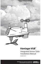
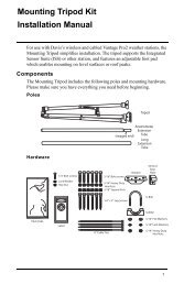
<strong>Fan</strong>-<strong>Aspirated</strong> ISS Addendum OverviewComponentsThe <strong>Fan</strong>-<strong>Aspirated</strong> ISS includes these components:Rain CollectorDebris Screen(place inside cone after installation)Solar Panel(wirelessISS only)MetricRain AdapterAnemometerVaneSIMHousingAnemometerBaseISS BaseControlHeadDripRingAnemometerArmWind Cups<strong>Aspirated</strong><strong>Radiation</strong><strong>Shield</strong>Anemometer Cable40' (12.2 m)The hardware shown here is provided for assembly and mounting:U-Bolts1/4" Flat Washers1/4" x 3" Lag Screws1/4" Lock Washers1/4" Hex NutsNut Plate#4 x 1-1/8"Machine Screw#4 Tooth Lock Washer#4-40 Hex Nut8" Cable Ties.05"Allen Wrench2
Tools for InstallationAdditional Components on Vantage Pro PlusVantage Pro2 Plus includesan ultraviolet (UV) sensor anda solar radiation sensor. Thesetwo sensors are mounted nextto the rain collector on yourISSSee the <strong>Integrated</strong> <strong>Sensor</strong> <strong>Suite</strong>about mounting and maintainingthese sensors.Do not to touch the smallwhite diffusers on top of theUV and solar radiation sensors.Oil from the skin reducessensor sensitivity.UV and Solar<strong>Sensor</strong>s<strong>Sensor</strong>Mounting ShelfTools for InstallationRefer to this section in your ISS Installation Manual on assembling theanemometer.Preparing the ISS for InstallationRefer to this section in your ISS Installation Manual on assembling theanemometer.Preparing the SIM for InstallationThe ISS sensors are connected by cables to the <strong>Sensor</strong> Interface Module(SIM), located inside the SIM housing. The SIM contains electronics thatmeasure and store weather values for transmission to the console via radio.The SIM housing protects the SIM from the elements and provides easyaccess to SIM cable connections.See the ISS Installation manual on checking the sensor connections to theSIM and for any additional sensor and wireless installation instructions.Preparing the Rain CollectorFollow these steps to prepare the rain collector for operation.1. Remove the rain collector cone from its base by rotating the conecounter-clockwise until its latches line up with openings which allowyou to lift it off. The cone fits in the base tightly and may require extrapressure to remove it when new.Note:Steady the base between your knees when you rotate the rain collector.3
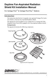
Preparing the <strong>Fan</strong>-aspirated ISS for Installation2. Carefully cut and remove the plastic cable tie (usually black in color)that holds the two-sided tipping bucket mechanism in place during shipping.Tipping bucket mechanismTwist off the rain collector cone Cut the plastic cable tiePreparing the Rain collectorNote:If installed, the UV and solar radiation sensor cables are routed through the base of the rain collector.Please make sure they do not get moved and make sure they do not interfere with the tippingbucket mechanism or with latching the cone back onto the base. See the ISS InstallationManual for instructions on inserting the optional metric measurement adapter.Preparing the <strong>Fan</strong>-aspirated ISS for InstallationThe radiation shield, fan, and solar panel used to power the fan come preassembledwith the ISS unit and require no additional assembly. However,the fan requires initial power from the pre-installed batteries. Tabs areincluded to ensure that the batteries that are installed in the fan-aspiratedhousing do not power the unit during shipping. To power the fan-aspiratedunit.1. Remove the cardboard packinginserts between the passiveshielding, the solar panel, and therain collector base and discard.2. Pull the tabs on the outside ofthe shielding slowly.3. Listen for a slight whir comingfrom the bottom of the ISSunit. This sound signifies thatthe fan is running.4
Applying Power and Testing CommunicationsApplying Power and Testing CommunicationsPowering the ISS and Testing Communication with theConsoleRefer to Wireless ISS Assembly section in your ISS Installation Manualfor the rest of the procedures required to power and test the ISS.Locating the ISS and AnemometerRefer to this section in your ISS Installation Manual.Mounting the ISSThe fan-aspirated version of the ISS, is mounted and installed just like theregular version of the ISS. Refer to this section in your ISS InstallationManual to mount the ISS.Additional Mounting OptionsRefer to this section in your ISS Installation Manual.<strong>Fan</strong>-<strong>Aspirated</strong> ISS Installation OptionsBatteriesThe Wireless <strong>Fan</strong>-<strong>Aspirated</strong> ISS is solar powered and is supplied with twoNiCad C-cell batteries that come pre-installed. The following options forbattery power exist:• Use two fan batteries for maximum length of overnight aspiration butwith slightly lower average daytime aspiration.• Use only one fan battery for some overnight aspiration but with slightlyhigher average daytime aspiration.• Remove both batteries for maximum daytime aspiration and no nighttimeaspiration.<strong>Fan</strong>-<strong>Aspirated</strong> ISS Maintenance• Keep the surfaces clean, since the <strong>Fan</strong>-<strong>Aspirated</strong> <strong>Radiation</strong> <strong>Shield</strong> isless effective when the surfaces are dirty. Remove dust from the solarpanel and the shield with a damp cloth.• Remove any debris obstructing air flow through the radiation shield,e.g., leaves, twigs, webs, and nests.• Avoid spraying insect killer of any kind into the radiation shield as thismay damage the sensors and the shield.• Once a year: replace the motor (Part # 7758), batteries, and remove anydebris lodged inside the unit.Disassemble the <strong>Radiation</strong> <strong>Shield</strong>Disassemble the radiation shield for routine cleaning, maintenance, and toreplace the batteries and motor. To disassemble the shield:5
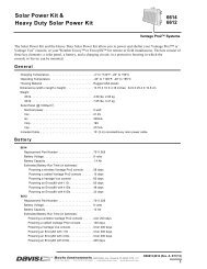
<strong>Fan</strong>-<strong>Aspirated</strong> ISS TroubleshootingNote:Please do not return items to the factory for repair without prior authorization.Contacting <strong>Davis</strong> Instruments(510) 732-7814 for Technical Support, Monday – Friday, 7:00 a.m. – 5:30p.m. Pacific Time.support@davisnet.com E-mail to Technical Support.(510) 670-0589 Fax to Customer Service or Tech Support.www.davisnet.com Copies of User Manuals are available on the “Support”page. Watch for FAQs and other updates. Subscribe to the e-newsletter.Theory of OperationThe diagram below shows how the <strong>Fan</strong>-<strong>Aspirated</strong> <strong>Radiation</strong> <strong>Shield</strong> drawsoutside air up through the sensor chamber and between the three walls surroundingthe sensor chamber.MOTORFANSENSORCHAMBERCross-section of <strong>Fan</strong>-<strong>Aspirated</strong> <strong>Radiation</strong> <strong>Shield</strong><strong>Fan</strong>-<strong>Aspirated</strong> ISS SpecificationsAspiration Rate . . . . . . . . . . . . . . . . . . 190 ft./min. (.96 m/s) (solarpowered,full sun), 80 feet/min. (0.4m/s) (battery only)<strong>Radiation</strong>-Induced Temperature Error. . 0.5°F (0.3°C)[At solar noon, insolation = 1040 W/m2]7
(Reference: RM Young model43408)Operating Temperature . . . . . . . . . . . . –40° to +140° F (–40° to +60° C)Non-operating Temperature . . . . . . . . . –50° to +158° F (–45° to +70° C)ISS Primary Power InputWireless ISS . . . . . . . . . . . . . . . . . . . . solar panelISS secondary power . . . . . . . . . . . . . . CR-123A 3-volt lithium battery (8months without sunlight to greaterthan two years depending on solarcharging)<strong>Fan</strong> Primary Power InputWireless ISS . . . . . . . . . . . . . . . . . . . . . solar panel<strong>Fan</strong> secondary power . . . . . . . . . . . . . . 1 or 2 - 1.2 Volt NiCad C-cellsFCC Part 15 Class B Registration WarningThis equipment has been tested and found to comply with the limits for a Class B digital device, pursuant to Part 15 of the FCC Rules.These limits are designed to provide reasonable protection against harmful interference in a residential installation. This equipmentgenerates, uses, and can radiate radio frequency energy and, if not installed and used in accordance with the instructions, maycause harmful interference to radio communications.However, there is no guarantee that interference will not occur in a particular installation. If this equipment does cause harmful interferenceto radio or television reception, which can be determined by turning the equipment on and off, the user is encouraged to try tocorrect the interference by one or more of the following measures:• Reorient or relocate the receiving antenna.• Increase the separation between the equipment and receiver.• Connect the equipment into an outlet on a circuit different from that to which the receiver is connected.• Consult the dealer or an experienced radio/TV technician for help.Changes or modification not expressly approved in writing by <strong>Davis</strong> Instruments may void the warranty and void the user's authorityto operate this equipment.IC: 378810-6328EC EMC ComplianceThis product complies with the essential protection requirements of the EC EMC Directive 89/336/EC.Addendum, <strong>Fan</strong>-<strong>Aspirated</strong> ISS InstallationRev A Manual (November 10, 2004)Document Part Number: 7395.252Product Number:6153, 6163Vantage Pro ® and Vantage Pro2 are trademarks of <strong>Davis</strong> Instruments Corp., Hayward, CA.© <strong>Davis</strong> Instruments Corp. 2004. All rights reserved.Information in this document subject to change without notice.