Integra Ci1 Quick Start Guide - Crompton Instruments
Integra Ci1 Quick Start Guide - Crompton Instruments
Integra Ci1 Quick Start Guide - Crompton Instruments
You also want an ePaper? Increase the reach of your titles
YUMPU automatically turns print PDFs into web optimized ePapers that Google loves.
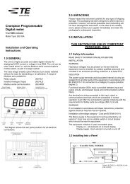
Setting-upIntroductionINTEGRA <strong>Ci1</strong>Digital Energy Meter for Single- andThree-phase Electrical SystemsModel Type: CI1-01Installation and OperatingInstructionsThe <strong>Integra</strong> <strong>Ci1</strong> digital meter is designed for accuratemeasurement and display of imported and exported real andreactive energy, since it was last reset, in terms of Wh, kWh,MWh, VArh, kVArh and MVArh for single phase, three-phase 3-or 4-wire supplies.This manual provides all the necessary instructions tosafely install and operate the instrument. However, formore in-depth operating instructions please refer tothe full manual on the <strong>Crompton</strong> <strong>Instruments</strong> website,www.crompton-instruments.com.MeasurementIn measurement mode, the buttons control the displayedmeasurement as follows:Displays the maximum current that can bemonitored. This reading is set on installationaccording to the current transformer in use.The small ‘A’ on the bottom line indicatesthat the display is showing Amps.Displays active energy measured since theunit was last reset. The display alternatesbetween Imported and Exported energyeach time the button is pressed. The bottomline of the display shows the import/exportmode and the Wh, kWh or MWh range. The1 and/or 2 symbol on the top lineflashes each time an output pulse isgenerated.Displays reactive energy measured sincethe unit was last reset. The displayalternates between Imported and Exportedreactive energy each time the button ispressed. The bottom line of the displayshows the import/export mode and the VArh,kVArh or MVArh range. The 1 and/or2 symbol on the top line flashes eachtime an output pulse is generated.This display indicates the phase sequencesof the measured voltages and currents,allowing a check that they are connectedcorrectly. The sequence can be 123 or 132but voltage (V) and current (I) sequencesmust be the same. A ‘V1--‘ or ‘I --‘ displayindicates a phase error of voltage or current,respectively.To enter set-up mode, firmly press the and buttonssimultaneously and hold for about 5 seconds until the passwordscreenappears. Setting-up is password-protected soyou must enter the correct password (default ‘0000’) beforeproceeding. If an incorrect password is entered, the displayreverts to measurement mode.To exit setting-up mode, press repeatedly until themeasurement screen is restored or hold CT and TEST buttonssimultaneously for 5 seconds.Setup Menu StructureChange passwordnnnn – 4-digit number, default ‘0000’Supply systems3-phase 3- or 4-wire, Single phaseCT Set maximum current that can be monitored according to CTin use. nnnn – 4-digit number 0001 to 9999Reset Resets cumulative energy measurement to zeroCommunication parameters for RS485 interface (optional)Modbus protocolBaud rate 2400/4800/9600/19200/38400Parity none/odd/evenStop bits 1 (1 or 2 if parity is None)RS485 network address nnn – 3-digit number 1 to 247Order – Norm/Rev indicates if Modbus word orderis normal or reversedJohnson Controls (JC) N2 protocolRS485 network address nnn – 3-digit number 1 to 255Relay pulse outputs (optional)OP1 kWh/kVArh (Active/reactive)Import or Export from output module 1OP2 kWh/kVArh (Active/reactive)Import or Export from output module 2Rate 0.001/0.01/0.1/1/10/100/1000/10,000 kWh orkVArh per pulsePulse width 200/100/60 msEnergy Unit/kilo/Mega1% limit on/offTestSFSSFHPhase sequenceDisplay on – all elements on to check displayDisplay toggle - Each element is turned on and offBuild numberFirmware versionMenu Option Selection1. Use the (up) and (down) keys to select the requireditem from the menu. Selection does not roll over frombottom to top of list or vice versa.2. Press to confirm selection.3. If an item flashes, then it can be adjusted by the andkeys. If not, there may be a further layer, e.g. Comms -Baud rate, before adjustment is possible.Press to select the lower layer.4. Having selected an option from the current layer, pressto confirm your selection. The SET indicator will come on.5. Having completed a parameter setting, press to return toa higher menu level. The SET indicator will go off and youwill be able to use the and keys for further menuselection.
6. On completion of all setting-up, press repeatedly untilthe measurement screen is restored.Number Entry ProcedureWhen setting-up the unit, some screens require the setting-up ofa number. In particular, on entry to the setting-up section, apassword must be entered. Digits are set individually, from left toright. The procedure is as follows:1. The current digit to be set flashes and is set using theand keys.2. Press to confirm each digit setting. The SET indicatorcomes on after the last digit has been set.3. After setting the last digit, press to exit the numbersetting routine. The SET indicator will go off.Installation92.0WarningsCaution: Risk ofElectric Shock• During normal operation, voltages hazardous to lifemay be present at some of the terminals of this unit.Installation and servicing should be performed only byqualified, properly trained personnel abiding by localregulations. Ensure all supplies are de-energisedbefore attempting connection or other procedures.• Terminals should not be user accessible afterinstallation and external installation provisions mustbe sufficient to prevent hazards under fault conditions.• This unit is not intended to function as part of asystem providing the sole means of fault protection -good engineering practice dictates that any criticalfunction be protected by at least two independent anddiverse means.• The unit does not have internal fuses thereforeexternal fuses must be used for protection and safetyunder fault conditions.• Never open-circuit the secondary winding of anenergized current transformer.• If this equipment is used in a manner not specified bythe manufacturer, protection provided by theequipment may be impaired.• Auxiliary circuits (communication & relay outputs) areseparated from metering inputs and 110-400V auxiliarycircuits by at least basic insulation. Such auxiliarycircuit terminals are only suitable for connection toequipment which has no user accessible live parts.The insulation for such auxiliary circuits must be ratedfor the highest voltage connected to the instrumentand suitable for single fault condition. The connectionat the remote end of such auxiliary circuits should notbe accessible in normal use. Depending onapplication, equipment connected to auxiliary circuitsmay vary widely. The choice of connected equipmentor combination of equipment should not diminish thelevel of user protection specified.92.0Cutout DetailsThe unit may be mounted in a panel of any thickness up to amaximum of 6 mm (0·25in). Leave enough space behind theinstrument to allow for bends in the connection cables. As thefront of panel enclosure conforms to IP52, it is protected fromdripping water. The unit is intended for use in a reasonablystable ambient temperature within the range -10 to +55°C. Donot mount the unit where there is excessive vibration or inexcessive direct sunlight.SafetyThe unit was designed in accordance with BS EN 61010-1:2001(IEC 61010-1:2001) – Permanently connected use, Normalcondition. Installation category III, pollution degree 2, basicinsulation for rated voltage. Measurement Category III.EMC Installation RequirementsWhilst this unit complies with all relevant EU EMC (electromagneticcompatibility) regulations, any additional precautionsnecessary to provide proper operation of this and adjacentequipment will be installation dependent and so the following canonly be general guidance:• Avoid routing wiring to this unit alongside cables andproducts that are, or could be, a source of interference.• The auxiliary supply to the unit should not be subject toexcessive interference. In some cases, a supply line filtermay be required.• To protect the product against incorrect operation orpermanent damage, surge transients must be controlled. Itis good EMC practice to suppress transients and surges atthe source. The unit has been designed to automaticallyrecover from typical transients; however in extremecircumstances it may be necessary to temporarily disconnectthe auxiliary supply for a period of greater than 10 seconds torestore correct operation.• Screened communication leads are recommended and maybe required. These and other connecting leads may requirethe fitting of RF suppression components, such as ferriteabsorbers, line filters etc., if RF fields cause problems.• It is good practice to install sensitive electronic instrumentsthat are performing critical functions in EMC enclosures thatprotect against electrical interference causing a disturbancein function.
WiringInput connections are made to screw clamp terminals. Choice ofcable should meet local regulations for the operating voltage andcurrent. The current inputs of this product are designed forconnection into systems via current transformers only.Instrument transformers used for connection to the meter mustbe of approved type and compliant with ANSI/IEEE C57.13 orIEC 60044-1, selected and sized appropriate to the supplynetwork being monitored. All negative current inputs arecommoned inside the unit and grounding should be at one pointonly. To minimise measurement errors, the CTs should begrounded as shown in the wiring diagram. CT secondaries mustbe grounded in accordance with local regulations. It is desirableto make provision for shorting links to be made across CTs topermit easy replacement of a unit should this ever be necessary.All connections are made to screw clamp terminals. Terminalsare suitable for copper wires only and will accept one 0·05 –2·5mm² (30 – 21AWG) stranded or solid core cable. <strong>Instruments</strong>are intended for panel mounting. Terminals must be enclosedwithin the panel. Use wire rated at 600V for main terminals, 60°Cminimum temperature. Terminal screws are fully tightened forshipment and must be undone before wire insertion. Terminalscrews should be tightened to 0·5Nm (4·4 lbf in) only.Additional considerations for three wire systemsThe neutral terminal (terminal N) is indirectly connected to thevoltage input terminals (terminals L1, L2, L3). When connectedto a three wire system the neutral terminal will adopt a potentialsomewhere between the remaining lines. If external wiring isconnected to the neutral terminal it must be connected to eitherthe neutral line or earth (ground) to avoid the possibility of electricshock from the neutral terminal.FusingThis unit must be fitted with external fuses in voltage andauxiliary supply lines. Voltage input lines must be fused with afast blow fuse 1A maximum. Auxiliary supply lines must be fusedwith a slow blow fuse rated 1A maximum (if product is poweredline-to-line, ensure both lines are fused). Choose fuses of a typeand with a breaking capacity appropriate to the supply and inaccordance with local regulations.A suitable switch or circuit breaker confirming to the relevantparts of IEC 60947-1 and IEC 60947-3 should be included in theinstallation. It should be positioned so as to be easy to operate,in close proximity to the equipment, and clearly identified as thedisconnecting device.Earth/Ground ConnectionsFor safety reasons, current transformer secondary connectionsshould be grounded in accordance with local regulations. Underno circumstances should the product be operated without anEarth connection.MaintenanceIn normal use, little maintenance is needed. As appropriate forservice conditions, isolate electrical power, inspect the unit andremove any dust or other foreign material present. Periodicallycheck all connections for freedom from corrosion and screwtightness, particularly if vibration is present.The front of the case should be wiped with a dry cloth only. Useminimal pressure, especially over the viewing window area. Ifnecessary wipe the rear case with a dry cloth. If a cleaning agentis necessary, isopropyl alcohol is the only recommended agentand should be used sparingly. Water should not be used. If therear case exterior or terminals should be contaminatedaccidentally with water, the unit must be thoroughly dried beforefurther service. Should it be suspected that water might haveentered the unit, factory inspection and refurbishment isrecommended.In the unlikely event of a repair being necessary, it isrecommended that the unit be returned to the factory or nearest<strong>Crompton</strong> <strong>Instruments</strong> / TE Connectivity service centre.SpecificationMeasurement InputsImported and exported energies are recorded.Three current inputs (six physical terminals) with 2·5mm²stranded wire capacity for connection of external CTs. Voltageinputs through 4-way fixed connector with 2·5mm² stranded wirecapacity. 3-Phase 3- and 4-wire and Single-phase 2-wireunbalanced. Line frequency measured from L1 voltage or L3voltage.Direct measurement of 173 to 500Vac L-L (100 to 289Vac L-N).Range of UseValues of measured quantities, components of measuredquantities, and quantities which affect measurement errors tosome degree, for which the product gives meaningful readings:Voltage5 … 120% of Range Maximum(below 5% of Range Maximum voltage,current indication may only be approximate)Current1 … 120% of nominalActive power 1 … 144% of nominal, 360MW maximumApparent power 1 … 144% of nominal, 360MVA maximumPower is only registered when voltage and current are within theirrespective range of use.AccuracyActive energy (Wh) Class 1 IEC 62053-21 section 4.6Reactive energy (VARh) ±1% of range maximumTemperature co-efficient Active energy = 0·018%/°C, typicalError change due tovariation of an influencequantity in the mannerdescribed in Section 6 ofIEC 688:1992Error in measurementwhen a measurand iswithin its measuringrange, but outside itsreference range2 × error allowed for the referencecondition applied in the test. Errordue to temperature variation asabove.2 × error allowed at the end of thereference range adjacent to thesection of the measuring range,where the measurand is currentlyoperating / being tested.Auxiliary SupplyThe unit is powered from an auxiliary a.c. or d.c. supply that isseparate from the metered supply, through a two-way fixedconnector with 2·5mm 2 stranded wire capacity.Operating range110 to 400V AC nominal ±10% (99-440V AC absolute limits)120 to 350V DC nominal ±20% (96-420V DC absolute limits)Frequency Range 45 to 66 HzBurden5VA nominal
Option ModulesPulsed output relays 1 per module(maximum 2 modules fitted per meter)Contact rating50mA max at 250V ACfor general switching applicationsTypeSolid state relayRS485 output module 1 channel per module(maximum 1 module fitted per meter)Type2-wire half duplexBaud rate 2400, 4800, 9600, 19200, 38400Reference Conditions of Influence QuantitiesInfluence Quantities are variables that affect measurement errorsto a minor degree. Accuracy is verified under nominal value(within the specified tolerance) of these conditions.Ambient temperature 23°C ±1°CInput waveform 50 or 60Hz ±2%Input waveform Sinusoidal (distortion factor


