mCq pCO - Standard + Heat Pump - McQuay
mCq pCO - Standard + Heat Pump - McQuay
mCq pCO - Standard + Heat Pump - McQuay

You also want an ePaper? Increase the reach of your titles
YUMPU automatically turns print PDFs into web optimized ePapers that Google loves.
Conditioning: <strong>pCO</strong> <strong>Standard</strong> chiller + heat pump User Guide ver. 2.9 02/11/99McQ<strong>pCO</strong><strong>Standard</strong> Chiller + <strong>Heat</strong> <strong>Pump</strong>McQ<strong>pCO</strong> ver2.9 02/11/99Main functions performed by <strong>pCO</strong>- Management of one heat pump or one chiller made up of 2 compressors equipped with1 capacity-controlled valve- Display of all measured values and set-points- Possibility of setting and successively modifying the regulation parameters- Indication of any off-normal condition via acoustic and visual signals (BUZZER andALARM MESSAGES)- USER-UNIT communication interface (KEYPAD and DISPLAY)- Possible connection to remote supervisor via RS422 serial line.- Possible connection to serial printerPag.1/61
Conditioning: <strong>pCO</strong> <strong>Standard</strong> chiller + heat pump User Guide ver. 2.9 02/11/99IndexMain functions performed by <strong>pCO</strong>----------------------------------------------------------------------- 1Index ------------------------------------------------------------------------------------------------------------ 2Hardware architecture--------------------------------------------------------------------------------------------- 3Keypad---------------------------------------------------------------------------------------------------------- 4Main Card------------------------------------------------------------------------------------------------------ 8Mounting <strong>pCO</strong> optional cards--------------------------------------------------------------------------- 10Mounting the Eprom ------------------------------------------------------------------------------------------------------------- 10Before requesting Service ------------------------------------------------------------------------------------------------------ 11Inputs / Outputs--------------------------------------------------------------------------------------------------- 11Analogue inputs -------------------------------------------------------------------------------------------- 11Digital inputs ------------------------------------------------------------------------------------------------ 12Digital outputs----------------------------------------------------------------------------------------------- 12Analogue output-------------------------------------------------------------------------------------------- 13Inputs and outputs connections ---------------------------------------------------------------------------- 14Connecting NTC temperature probes --------------------------------------------------------------------------------------- 14Connecting Keller pressure transducer ------------------------------------------------------------------------------------- 14Connection to the tension digital inputs ------------------------------------------------------------------------------------- 16Connecting the digital outputs ------------------------------------------------------------------------------------------------- 16Connecting the analogue outputs--------------------------------------------------------------------------------------------- 17The program-------------------------------------------------------------------------------------------------------- 18General description---------------------------------------------------------------------------------------- 18Software initialization ------------------------------------------------------------------------------------- 19Configuration Guide--------------------------------------------------------------------------------------- 20Use guide ---------------------------------------------------------------------------------------------------- 21Status of the system------------------------------------------------------------------------------------------------------------- 21Water temperature regulation-------------------------------------------------------------------------------------------------- 23Compressors start-up (with and without capacity-controlled) ---------------------------------------------------------- 27Reversing cycle electrovalves ------------------------------------------------------------------------------------------------- 28Defrosting cycle------------------------------------------------------------------------------------------------------------------- 28Electropump ----------------------------------------------------------------------------------------------------------------------- 29Fans and fans inverter ---------------------------------------------------------------------------------------------------------- 31Times ------------------------------------------------------------------------------------------------------------------------------- 32Antifreeze procedure ------------------------------------------------------------------------------------------------------------ 33Low pressure pressurestat----------------------------------------------------------------------------------------------------- 33Double Setpoint------------------------------------------------------------------------------------------------------------------- 34Time-zones ------------------------------------------------------------------------------------------------------------------------ 34Supervisor --------------------------------------------------------------------------------------------------- 36Printout ------------------------------------------------------------------------------------------------------- 39Masks tree----------------------------------------------------------------------------------------------------------- 40Selectable parameters------------------------------------------------------------------------------------ 58Pag.2/61
Conditioning: <strong>pCO</strong> <strong>Standard</strong> chiller + heat pump User Guide ver. 2.9 02/11/99Hardware architectureFIG. 1The figure above shows <strong>pCO</strong>'s hardware architecture:• Main Card with CPU, BIOS, application SW and I/O• Keypad-led-display: terminal unit• Connection cable between terminal and main cardPag.3/61
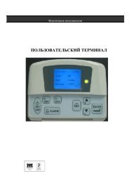
Conditioning: <strong>pCO</strong> <strong>Standard</strong> chiller + heat pump User Guide ver. 2.9 02/11/99KeypadThe figure below shows <strong>pCO</strong>'s front panel with open front lid.The microprocessor-based terminal is equipped with lcd (4 x 20), keypad and led indicatorswhich make it extremely simple to set the working parameters (set-points, differential, alarmthresholds) and to perform any other regulation operation.The connection between terminal unit and main card is not necesssary during <strong>pCO</strong>'s normalfunctioning.menu I/O set prog?infoon-off alarm enterThe terminal unit is necessary to program the unit and display its working parameters. Itenables you to perform the following operations:• initial programming via password;• possibility of modifying run-time any working parameter; display of any alarm condition (viaalarm messages and buzzer);• display of all measured values.Technical specificationsThe unit is powered via the main card by means of a 6-way connector.The working temperature should range between 0 and 50 °C, the storage temperature between- 20 and 50 °C.There are 10 buttons on the polycharbonate front panel plus 5 buttons in silicone translucentrubber.There are 3 led indicators below the rubber buttons, 10 led below the polycharbonate frontpanel plus 5 extra (optional) leds on the right side of the display.Electromagnetic, 2 KHz self-oscillating buzzer.Pag.4/61
Conditioning: <strong>pCO</strong> <strong>Standard</strong> chiller + heat pump User Guide ver. 2.9 02/11/99The electronic card, that includes the support for led indicators and buttons, has been housedinside a standard plastic case together with the display.Panel and wall mounting cases available.As you can see on pag. 4, <strong>pCO</strong>'s housing comes complete with a front panel lid that opens witha max. span of 150 °C.When the lid is closed, only the five backlit silicone rubber keys will be directly accessed.<strong>pCO</strong> comes complete with a small 15-button keypad. Keypad and display represent the UserInterface.menu I/O set prog?infoon-off alarm enterThe main parameters or parameters loops are directly accessed by keypad by acting on thefollowing keys:ON / OFFon-offOperates and stops the controlled devices.ALARMalarmGoes to the first active alarm mask and silences thebuzzer. If pressed a second time on the active alarmmask, it resets the alarm and returns to the first maskagain.If you press this button and there are no active alarms,the message 'NO ACTIVE ALARM' will appear on thedisplay.All alarm masks can be scrolled by pressing the UPand DOWN buttons.UP & DOWN When the cursor is at the HOME position (position 0,0on the display), these buttons allow you to read all themasks of a specific section.When the cursor is within a numeric field, the UP &DOWN buttons allow you to increase anddecreasethevalue on which the cursor is positioned.When the cursor is on a choice field, pressing thesebuttons allows you to display all the options available(eg. Yes/No).Pag.5/61
Conditioning: <strong>pCO</strong> <strong>Standard</strong> chiller + heat pump User Guide ver. 2.9 02/11/99ENTERpositionenterWhen the cursor is on the selection masks, pressENTER once to move the cursor to the first introductionfield.Press ENTER again to confirm the set value and tomove the cursor to the next field. When the cursorreaches the last field, it will return to the HOMEagain.MENUmenuGoes to the MAIN maskINFO?infoGoes to the M_VERSION maskMAINTGoes to the M_VIS_TIMER maskPRINTERGoes to the M_PRINT mask (models with printer only)I/OI/OGoes to the M_SYNOPTIC1 maskTIMEGoes to the REG_CLOCK_US maskSETsetGoes to the M_VIS_SETPOINT maskPROGprogYou have to introduce the correct password to accessthe M_PASS_USER mask.MENU+PROGmenu+progPress and release the MENU and PROG buttonsSIMULTANEOUSLY.Then, introduce the password to access theM_PASS_MANUFAC mask.Led IndicatorsThe keypad buttons and the green led indicators are placed side by side.Any time you press a button, the corresponding green led will light up thus making it easier forthe you to identify which mask section you are using.Pag.6/61
Conditioning: <strong>pCO</strong> <strong>Standard</strong> chiller + heat pump User Guide ver. 2.9 02/11/99When pressing the MENU+PROG buttons to access the configuration parameters, it is the ledindicator corresponding to the PROG button that will light up.There are other three led indicators under the following rubber buttons:1. ON / OFF button green led indicator -Indicates that the unit is ON.2. ALARM button red led indicator -Indicates an alarm condition.3. ENTER button yellow led indicator -Indicates correct power supply.When the unit is forced into the manual operation mode (in this case the unit turns off), the ledcorresponding to the ON/OFF button will flash.It will stop blinking as soon as the Operator disenables all devices by means of the manualprocedure.In the event of off-normal condition the led relative to the ALARM button will flash and thebuzzer will sound.Press the ALARM key once to display the type of alarm occurred and disactivate both led andbuzzer.By pressing the ALARM key a second time you will cancel the stored alarm but if the cause thatgenerated the alarm still persists, the same alarm message will appear again.All alarms must be manually reset (by pressing the ALARM key) before reactivating the relativedevices.If you do not perform any operation within 5 minutes, the unit will return to the Main mask(accessible by the MENU button) where you can display the values measured by thetemperature probe at evaporator inlet.Back part of the cardThe terminal card includes:# the microprocessor# the outputs for connections to <strong>pCO</strong> and serial printer<strong>pCO</strong>CONTROLCONNECTORPRINTERCONNECTORMICROPROCESSORPag.7/61
Conditioning: <strong>pCO</strong> <strong>Standard</strong> chiller + heat pump User Guide ver. 2.9 02/11/99Main CardThe controller's card is the heart of the entire system since it contains the microprocessor thatperforms the control algorithm.GG041J9J8B86+24VdcB72B63J15J14AVSSB5B45AVSSVG0B3VG1B2Y1AVSSY0B1ID11RIDCM2ID10ID11ID9ID8ID12RID7ID6R11ID12NOCNCR117IDCM1ID5ID4ID3ID2R10NOCNCR10R1ID1CNOR1R9NOCNCR9R2CNOR2R8NOCR8R3CNOR3R7NOCR7R4CNOR4R6NOCR6R5CNOR5R13NOCR13R12CNOR12Components of the Main Card(1) Power supply connector 24 Vac(2) Telephone connector to the terminal unit (RS485) or to local network connection(3) Clock card (optional)(4) RS422 optoisolated card for serial line connection to supervisory/telemaintenance systems(5) Pin strips to be positioned as follows, depending on your application requirements:J8: position 1-2 for connecting the card to a terminal unit or to thesupervisor; position 2-3 just allows a local network connectionJ9: position 1-2 enables remote reset from the supervisor;J14: position 1-2 enables tension input B5,position 2-3 enables current input B5.J15: position 1-2 enables tension input B6,position 2-3 enables current input B6.(6) Program Eprom.(7) Output relaysRxx:Relay output connectorsPag.8/61
Conditioning: <strong>pCO</strong> <strong>Standard</strong> chiller + heat pump User Guide ver. 2.9 02/11/99No:ormally open contactNc:Normally closed contactC: Common referenceID:Digital inputsIDCM: Common for digital inputsBx:Analogue inputAVSS: Reference for analogue inputsYx:Analogue outputsVG1/0: Analogue outputs power source 24VTechnical specificationsMAIN CARD - MECHANICAL SPECIFICATIONSCard, 16.5 DIN modulesFasteners107 x 292,5 mm6 fastners {\SIMBOLO 198 \f "Symbol"} 4 mm plus optionalsupport for DIN rail mountingTerminal blockTypemale/female plug-in connectorsMax. current16 AMax. voltage250 VacMax. cable section 2,5 mm 2CONNECTION TO KEYPAD - DISPLAY UNIT (see figure)TypeConnectorDriverDistanceAsyncronous, half duplex, 2-wire leadtelephone-type 6-way leadbalanced differential CMR 7 V (type RS422)max. 1 KmAlternatively, Carel local network connection available. In this case interfacing the unit to thesupervisory system will not be possible.Pag.9/61
Conditioning: <strong>pCO</strong> <strong>Standard</strong> chiller + heat pump User Guide ver. 2.9 02/11/99Mounting <strong>pCO</strong> optional cardsClock cardThe clock card is necessary to display the current time and date and to perform a time-zonecontrol action.Connect it to connector no. 3 shown in the figure onpage 7.In the event of power supply failure to <strong>pCO</strong>, the clockcard will be powered by a rechargable lithium battery(45 mA/h, min. operating time = one month).MNEWCLOCK0CodeOptoisolated RS422 serial cardThe RS422 serial card allows <strong>pCO</strong> to be networkconnected into local or remote supervisory andtelemaintenance systems.Connect this card to the relative connector (4) shownon page 7.PCOSER0000CodeConnection to a 80-column serial printer: electrical diagram.connettore9 poli - femmina<strong>pCO</strong>RXTXGNDData Terminal ReadyClear to SendData Set ReadyCarrier Detect235486123768205connettore25 poli - maschiostampanteMounting the EpromThe Eprom must be inserted into the main card.An arrow on the label of the eprom indicates how to insert it correctly.When inserting the eprom into its socket payattention to align its polarity correctly (the notch onthe eprom must coincide with that of the socket).Insert the eprom carefully without bending orbreaking its small pins.Pag.10/61
Conditioning: <strong>pCO</strong> <strong>Standard</strong> chiller + heat pump User Guide ver. 2.9 02/11/99Before requesting ServiceTHE UNIT DOES NOT STARTLed of the Enter key off, Lcd off, other led indicators off.Cause:a. no mains voltageb. transformer (220 - 24V) is not powered with 24 Vacc. 24V power supply connector is not well plugged-inTHE UNIT IS ON BUT:the alarm led indicator is ONthe LCD shows no messages or random messagesthe buzzer soundsCause:a. eprom inserted with wrong polarityb. pins of the eprom bentc. microprocessor chip damaged: contact qualified service personneld: telephone cable from terminal to main card is not correctly connectedWRONG INPUT SIGNALS READINGCause:a. incorrect probe connectionsb. probes' wires must be placed far from electrical noises (power cables, contactors, hightension cables, etc.)c. incorrect connection between interfaces and controller (flat cables)d. incorrect power source to interfacesFAULTY EEPROMa. contact qualified service personnel<strong>pCO</strong> TURNS OFF AND ON REPEATEDLY (WATCH-DOG) OR IT OPERATES SOME(DIGITAL AND/OR ANALOGUE) OUTPUTS AT RANDOM.Cause:a. incorrect power supplyb. power cables are too close to the microprocessors of the interfaces and to the controlcard.Inputs / OutputsAnalogue inputsPag.11/61
Conditioning: <strong>pCO</strong> <strong>Standard</strong> chiller + heat pump User Guide ver. 2.9 02/11/99TERMINAL SCREEN FUNCTIONPRINTJ2 - 1 B1 Water temperature at evaporator inletJ2 - 2 AVSS Common to analogue inputsJ2 - 3 B2 Water temperature at evaporator outletJ2 - 4 B3 External air temperature/(Temperature coil 1 only MHP)J2 - 5 AVSS Common to analogue inputsJ2 - 6 B4 Open (Temperature coil 2 only MHP)J2 - 7 B5 High pressure circuit no. 1J2 - 8 AVSS Common to analogue inputsJ2 - 9 B6 High pressure circuit no. 2Digital inputsTERMINAL SCREEN FUNCTIONPRINTJ4 - 1 ID1 <strong>Pump</strong>down Circuit 1J4 - 2 ID2 Winter / Summer (only MHP)J4 - 3 ID3 Flow switchJ4 - 4 ID4 <strong>Pump</strong>down Circuit 2J4 - 5 ID5 High Pressure switch Circuit 1J4 - 6 IDCM1 Common to digital inputs J4 - 1 / 5J3 - 1 ID6 High Pressure switch Circuit 2J3 - 2 ID7 Oil differential pressurestat compressor no. 1J3 - 3 ID8 Oil differential pressurestat compressor no. 2J3 - 4 ID9 Low pressure pressurestat circuit 1J3 - 5 ID10 Low pressure pressurestat circuit 2J3 - 6 IDCM2 Common to digital inputs J3 - 1 / 5J21 - 1 ID11 Compressor circuit breaker no. 1J21 - 3 ID11R Common to digital input J21 - 1J21 - 5 ID12 Compressor circuit breaker no. 2J21 - 7 ID12R Common digital input J21 - 5Digital outputsTERMINAL SCREEN FUNCTIONPRINTJ5 - 4 / J5 - 5 C1 - NO1 Liquid Solenoid compressor no. 1J5 - 1 / J5 - 2 C2 - NO2 Liquid Solenoid compressor no. 2Pag.12/61
Conditioning: <strong>pCO</strong> <strong>Standard</strong> chiller + heat pump User Guide ver. 2.9 02/11/99J6 - 10 / J6 - 11 C3 - NO3 Fan 2° step Circuit 1 (Chiller)/Rversing cycle electrovalve no.1 (MHP)J6 - 7 / J6 - 8 C4 - NO4 Fan 2° step Circuit 2 (Chiller)/Rversing cycle electrovalve no.2 (MHP)J6 - 4 / J6 - 5 C5 - NO5 Compressor no. 1J24 - 7 / J24 - 8 C6 - NO6 Compressor no. 2J24 - 4 / J24 - 5 C7 - NO7 ElectropumpJ24 - 1 / J24 - 2 C8 - NO8 UnusedJ22 - 9 / J22 - 10 C9 - NO9 Capacity-controlled compressor no.1J22 - 5 / J22 - 6 C10 - NO10 Capacity-controlled compressor no.2J22 - 1 / J22 - 2 C11 - NO11 General alarmJ6 - 1 / J6 - 2 C12 - NO12 Fan 1° step Circuit 1J24 - 10 / J24 - 11 C13 - NO13 Fan 1° step Circuit 2Analogue outputTERMINAL SCREEN FUNCTIONPRINTJ20 - 3 Y0 - VG0 Fans inverter Circuit no.1 (Optional)J20 - 4 Y1 - VG0 Fans inverter Circuit no.2 (Optional)Pag.13/61
Conditioning: <strong>pCO</strong> <strong>Standard</strong> chiller + heat pump User Guide ver. 2.9 02/11/99Inputs and outputs connectionsConnecting NTC temperature probesAVSSBnThe two cables of the NTC probe have no polarity so connect them as you like.CODES "NTC" PROBES:code: NTC030W000 code: NTC060W000 code: NTC120W000The probe signal is an ohm value depending on temperature. The table shows differentresistance values at different temperatures. Disconnect the probe at the interface input andmeasure its resistance at its terminal so as to infer the corresponding temperature value fromthe table:°C: -20; -15; -10; -5; 0; 5; 10; 15; 20; 25; 30; 35KOhm: 67.71; 53.39; 42.25; 33.89; 27.28; 22.05; 17.96; 14.68; 12.09; 10.00; 8.31; 6.94Connecting pressure transducerIf your unit includes pressure probes, connect them to terminals B5 and B6 asshown in thediagram below.Transducer - interface connectionSeries 21 / 22Delivery side 0 : 30 bar ALCO PT1-30A 0712526(Alternative) 0 : 30 bar Code SPK30000000Connector J2J2-7 / B5J2-8 / AVSSJ2-9 / B6Connector J1J1-1 / B8J1-2 / +24VJ1-3 / B7WhiteWhiteBrownBrown = PowerWhite = SignalConnect the transducers directly to the interfacePag.14/61
Conditioning: <strong>pCO</strong> <strong>Standard</strong> chiller + heat pump User Guide ver. 2.9 02/11/99IMPORTANT:Set the 4-20 mA configuration by placing the jumper ofconnectors J14 (referring to B5) and J15 (referring to B6) asindicated in the figure on the left.3 2 1In case of errors in the reading of these probe check:- that analogue inputs accept 4 ÷ 20 mA signal (see figure)- that the limits of the set probes correspond to the actual probes- that the correct connection to hold pressureBy measuring voltage at terminals Bn and AVSS you can abtain the probe signal current sincethe impedance of the input is 50 Ohm. The pressure value can be determined as follows:⎛ V⎝ R⎞0.004⎠Fs− Fsmmax minPs= ⎜ − ⎟ ×+0.016P s pressure value (bar)V m voltage measure (V)R Input impedance (Ohm)Fs max , Fs min high and low probe limits (bar) (default <strong>McQuay</strong> = 0 – 30)FsminPag.15/61
Conditioning: <strong>pCO</strong> <strong>Standard</strong> chiller + heat pump User Guide ver. 2.9 02/11/99Connecting the analogue outputsconnector <strong>pCO</strong>10 Vdc24 VacVG0VG1Y1groundoutput 2powerY0output 1device (fan inverter)The figure above shows <strong>pCO</strong>'s analogue outputs connections. Power terminals VG0 and VG1by 24 Vac.If the device connected to <strong>pCO</strong> is powered by 24 Vac, it is recommended to power alsoterminals VG0 and VG1 or draw power supply from terminals G0 and G on <strong>pCO</strong> card. Connectall devices (inverter, valves, etc.) either between terminals VG0 and Y0 or between VG0 andY1. As for the fans inverter, connect it between terminals VG0 and Y0 (see figure above).Pag.17/61
Conditioning: <strong>pCO</strong> <strong>Standard</strong> chiller + heat pump User Guide ver. 2.9 02/11/99The programGeneral descriptionThis application program has been designed to control a chiller or a heat pump equipped withmax. 2 compressors.The program controls the water temperature of the system keeping it within the limits set by theUser. Each circuit controls and regulates:- one compressor;- one capacity-controlled routine;- two condensation-removal fans;- one electrovalve necessary to reverse the refrigeration cycle (winter/summer) and to performdefrosting cycles.The temperature control is based on a Proportional or Proportional + Integral regulation logic,depending on the User's actual application requirements.A series of special settings allow you to ensure long life to the compressors through dedicatedalarms (circuit breakers and pressurestat interventions) and times management (including:minimum On routine of the compressor, time-interval between two consecutive On routines,time-interval between On routines of different compressors).The most important parameters (set-point, alarm thresholds, alarms) can be displayed (lcd 4 x20) and modified via keypad according to the User's requirements.12 digital inputs - connected to mechanical/electrical external alarm sensors - are meant todetect any off-normal condition forcing, if necessary, the controlled device to stop.In the event of abnormal working conditions, the operating personnel will be alerted by a redled indicator placed below the ALARM button and by the buzzer. The display will also showwhich type of off-normal condition has occurred.Alarm and temperature masks can be freely accessed whereas ALL SELECTION MAKS CANBE ACCESSED ONLY BY A SECRET KEY WORD KNOWN ONLY BY QUALIFIEDPERSONNEL.The key words are:0003 MAINTENANCE (QUALIFIED OPERATOR)0018 ASSISTANCE (SERVICE)XXXX MANUFACTURER (FACTORY)In this way you will be allowed to enter special fields where you will set the most importantworking parameters such as number of compressors, time-intervals, set-points, etc.).One of the protected sections will permit you to initialize <strong>pCO</strong> with factory-set parameters so asto make the configuration procedure even easier and faster.This program application also allows network connections into supervisory or telemaintenanceservices so as to ensure the remote control and management of the entire installation and theoptimization of maintenance procedures in the event of off-normal conditions.Connection to a 80-colums serial printer allows you to get periodic printouts of any alarmoccurred as well as reports of the values measured by the probes.Pag.18/61
Conditioning: <strong>pCO</strong> <strong>Standard</strong> chiller + heat pump User Guide ver. 2.9 02/11/99Software initializationInitializing the software means to set a series of important parameters such as:- number of compressors and fans- control parameters (set-points, times, alarm thresholds, etc.)All set data are permanently stored and retrieved any time <strong>pCO</strong> is turned ON.The very first time <strong>pCO</strong> is turned ON, we recommend cancelling the original data since theymight be unsuitable for your application requirements and then loading the factory-setparameters so as to make the initialization procedure fast and easy. Follow these indications:- Turn <strong>pCO</strong> ON. After a few seconds the main mask - MENU MASK - will appear on thedisplay. When starting <strong>pCO</strong> the very first time, ignore any alarms since they probably resultfrom incorrect data.- Press MENU + PRG simultaneously.Now you have to digit the manufacturer password 1 , necessary to prevent unauthorizedaccess to the operational parameters (configuration section).- Digit the correct password. After that a menu mask with 4 options will be displayed. Press first'Down' then 'Enter' to access the Initialization mask whereby you can set the entire range offactory-set parameters (standard configuration for refrigeration units).If some standard values do not suit your application requirements, you can simply change themby entering the dedicated selection mask/s.1 MANUFACTURER password "XXXX" . We recommend keeping the password secret so as toprevent unauthorised access to the operational parameters.The Manufacturer password can be used when performing preliminary operations and any timeyou do not manage to gain access to the configuration mask by the SERVICE password.Pag.19/61
Conditioning: <strong>pCO</strong> <strong>Standard</strong> chiller + heat pump User Guide ver. 2.9 02/11/99Configuration GuideNumber of compressorsThe factory-set number of compressors to be controlled is one (default value). Should your unitcomprise two compressors, enter the protected mask (via manufacturer password, see sectionabout masks below) and change the default parameter.The system can control up to 2 compressors (max.) plus their relative capacity-controlledroutines.The capacity-controlled routine can be operated according to two different modes:- DWM COPELAND logic: the capacity-controlled routine occurs when the output is closed;- FEDDERS logic: the capacity-controlled routine occurs when the output is open.Number of fans<strong>pCO</strong> manages 2 fans, one per circuit. The fans will be operated on the basis of the controller'sfunctioning mode, that is Winter or Summer:Summer functioning mode:Fans are operated according to the HIGH PRESSURE values measured by thepressuretransducers. If there are no pressure probes, the fans' activation will depend on the relativecompressors (fan on when compressor on and vice versa).Winter functioning mode:Fans and compressors will be activated and stopped at the same time.During a defrosting cycle the fan of the circuit undergoing defrosting will be stopped.In the event of circuit breakers (fan/flowmeter circuit breaker, etc.) the fans will be stoppedimmediately.Optional devicesYou can enhance the functions of the <strong>pCO</strong> controller by adding a series of optional devices(RS422 serial card, printer cable, clock card) that can be enabled by simply acting on thededicated masks.The RS422 card interfaces <strong>pCO</strong> to a supervisory network that can receive all data and alarmsfrom <strong>pCO</strong>.A dedicated cable will allow you to connect <strong>pCO</strong> to an external printer.Depending on the option selected, you will have to set in the dedicated masks time and date (toenable the clock card) or <strong>pCO</strong>'s identification number (so as to address messages correctlywhen the controller is network-connected into a supervisory/telemaintenance system by meansof the RS422 card).You can get periodic or immediate printouts of the values measured by the probes; in the eventof off-normal conditions, the relative alarm will be immediately printed.Pag.20/61
Conditioning: <strong>pCO</strong> <strong>Standard</strong> chiller + heat pump User Guide ver. 2.9 02/11/99Use guideStatus of the systemThe system can be ON, OFF or in the MANUAL functioning mode.To turn ON the chiller or heat pump and consequently start the regulation process, follow theseindications:• press the ON button (led indicator ON);• be sure that the daily or weekly time-zones control action has been enabled;• for remote on/off be sure that digital input no. 1 is closed;• be sure that - in case of network connection to a supervisory unit - the two units are correclyconnected;• the unit must not be in the manual functioning mode;• there must be NO alarm conditions (eg. flowmeter alarm).If all these conditions occur, the green led will light up.When the system is ON, compressors and fans will be operated on the basis of the valuesmeasured by the temperature and pressure transducers.If one of the above conditions does not occur, the unit will remain in the OFF status.The display and the ON led indicator will inform the User of the status of the entire system: inparticular, the last row of the main mask (which can be accessed by pressing the 'MENU'button) will show one of the following messages:- Unit OnWhen the unit is On, all devices can be operated.The ON/OFF led indicator is On.NOTE: On the MHP unit are available the terminals for connected a remote digital signal forcontrol Summer/Winter: when tehe digital input number 2 is ON the unit is controlledSUMMER, when the digital input number 2 is OFF the unit is controlled WINTER.To verify the distance of the remote digital contacts: the remote digital contacts are connectedon the circuit 24 Vac and the power transformer installed is 50VA. The installation of auxiliaryrelay is the best solution.It is raccomanded, however, to execute the following operations:1) to stop the unit and to attend the stop of motor pump evaporator electrical relay2) to change the function3) to start the unit.- Unit OffWhen the unit is Off, it is not possible to operate the connected devices.The ON/OFF led indicator is Off.- Off status via supervisory unitPag.21/61
Conditioning: <strong>pCO</strong> <strong>Standard</strong> chiller + heat pump User Guide ver. 2.9 02/11/99The controller's Off status has been forced by the supervisory pc. All connected devices cannot be operated.When in this status, the ON/OFF led indicator will flash; the controller can be turned onvia supervisory pc or simply by pressing the ON button on the controller's keypad.It will be possible to turn on the controller via supevisory pc only if the controller's ONled indicator is ON.When the unit has been turned off by acting on the Off button (local Off), it will not bepossible to turn it on again via external command (this ensures complete safety to theentire system).- Off status determined by time-zones control actionThe Off status has been determined by a time-zones control action.When in this status, all connected devices can not be operated.The ON/OFF led indicator is ON.The unit will re-start as soon as the time-zone control action instructs the system to start again.- Manual procedureThe manual procedure can be operated by selecting it on the dedicated mask ('maintenanceloop' protected by the key word).When the unit is on, the activation of the manual procedure forces the unit into the Off status;therefore it will be possible to operate all connected devices manually, with the exception of thetemperature control and of any alarm condition. When in the manual procedure status, the ONled indicator flashes.The manual procedure will be disenabled as soon as all the devices undergoing such aprocedure are disenabled or simply by pressing the ON/OFF button.Pag.22/61
Conditioning: <strong>pCO</strong> <strong>Standard</strong> chiller + heat pump User Guide ver. 2.9 02/11/99Water temperature regulationWater temperature can be regulated by means of a Proportional (P) or Proportional + Integral(P+I) control action, according to your specific application requirements.PROPORTIONAL CONTROL:since the set-point represents the ideal working condition, the <strong>pCO</strong> controller will operate itsconnected devices so as to reach the set-point in a proportional way, that is proportionally tothe distance between the actual condition and the set-point.The control action depends on the differential zone selected by the User:within this zone <strong>pCO</strong> will minimize the action of the connnected devices as the actualconditions get closer to the set-point and vice versa.PROPORTIONAL + INTEGRAL CONTROL:besides what performed by the proportional mode, the P+I control action will also rely on the'time' factor. A time constant (in seconds) will determine the velocity with which the controllerperforms its actions (less seconds, higher velocity). Usual time constant = 600 seconds.SET-POINT AND DIFFERENTIALSET-POINT ==> selectable in ºC; ideal working condition.DIFFERENTIAL ==> selectable in ºC; indicates the working range of the controller.temperature control zonesetpointdifferentialwatertemperatureIn the application shown in the figure above the set-point has been set so as to represent theCENTRAL point of the regulation zone.Pag.23/61
Conditioning: <strong>pCO</strong> <strong>Standard</strong> chiller + heat pump User Guide ver. 2.9 02/11/99POSITION OF THE STEPSSTEPS POSITION - Summer Functioning Mode -STEPS POSITION - Winter Functioning Mode -on ===> ACTIVATION OF THE STEPoff ===> DISACTIVATION OF THE STEPIn the SUMMER functioning mode the steps will activate when the temperature rises anddisactivate when it falls.In the WINTER functioning mode the steps will activate when the temperature falls anddisactivate when it rises.The steps' effect consists of moving the set-point to the left (SUMMER functioning mode) or tothe right (WINTER functioning mode) so as to reach the ideal working condition (set-point).Pag.24/61
Conditioning: <strong>pCO</strong> <strong>Standard</strong> chiller + heat pump User Guide ver. 2.9 02/11/99COMPRESSORS SET-POINT AND WORKING ZONEThe water temperature control action will be based on the selected set-point and differential.Depending on the selected devices, the following configurations will be possible:SINGLE COMPRESSOR UNIT WITHOUT CAPACITY-CONTROLLED ROUTINE'SUMMER' FUNCTIONING MODE'WINTER' FUNCTIONING MODESINGLE COMPRESSOR UNIT WITH 1 CAPACITY-CONTROLLED STEPNote: the example above refers to cooling applications ('Summer' functioning mode).For heating applications ('Winter' functioning mode), the steps will be positionedspecularly with respect to the set-point.Pag.25/61
Conditioning: <strong>pCO</strong> <strong>Standard</strong> chiller + heat pump User Guide ver. 2.9 02/11/99TWO-COMPRESSOR UNIT WITHOUT CAPACITY-CONTROLLED ROUTINENote: the example above refers to cooling applications (Summer mode).For heating applications (Winter mode), the steps will be positioned specularly withrespect to the set-point.TWO-COMPRESSOR UNIT WITH 1 CAPACITY-CONTROLLED ROUTINE PERCOMPRESSORNote: the example above refers to cooling applications (Summer mode).For heating applications (Winter mode), the steps will be positioned specularly withrespect to the set-point.The best working condition is achieved when the unit manages to reach and keep the set-pointvalue without operating any of the connected devices.If the unit works as a heat pump, the compressors' position on the diagrams will be in thenegative field of the proportional zone.Important: the regulation of the water temperature will depend either on the water temperatureprobe at evaporator inlet or evaporator outlet, as required by the User.Pag.26/61
Conditioning: <strong>pCO</strong> <strong>Standard</strong> chiller + heat pump User Guide ver. 2.9 02/11/99It is also possible to set a dead (neutral) zone around the set-point permitting the compressors -as well as the fans when working in freecooling mode - to remain off.In this way the steps of both fans and compressors will be moved on the right with respect tothe selected dead zone. The example below shows the position of the steps after havingselected a neutral zone around the set-point.dead zoneC = compressorP = parzializationC1P1C2P2setpointdifferentialwatertemperatureNote: the range of the dead zone must be inferior to the selected differential otherwisethe connected devices will not activate.Compressors start-up (with and without capacitycontrolled)Any time the compressor is instructed to start, the relative contactor will energize and -depending on the value of the water temperature at evaporator inlet or outlet - the controllerwill:- instruct the compressor to start;- energize the LIQUID SOLENOID valve.- the compressor will start.Compressors shiftSelecting the compressors shift ensures longer life to the compressors.This procedure, in fact, makes them work in a very balanced way and compensates the numberof their on/off routines as well as their working hours.The shift is based on a F.I.F.O. logic: the first compressor that starts will be the first to bestopped.At the very beginning this logic might cause an unbalanced compressors management but thesystem will gradually settle.Upon a call for compressor start-up, the logic will be as follows:- the compressor that has been Off for the longest time-interval will be the first to start;- the first compressor that starts will be the first to be stopped;- any compressor will start again only after all the other compressors have started once.Capacity-controlled routines do not undergo shifts.Pag.27/61
Conditioning: <strong>pCO</strong> <strong>Standard</strong> chiller + heat pump User Guide ver. 2.9 02/11/99Compressors timer<strong>pCO</strong> also controls the working hours of the compressors.Set the required value (default 10,000 hours) in the dedicated mask. When the compressorsreach the set threshold an alarm message (indication only) prompting maintenance will bedisplayed.It is possible to zero down the timer relative to each single compressor.Reversing cycle electrovalvesThese valves are used in units working as 'heat pumps' in order to pass from the Summer tothe Winter functioning mode.In the Winter mode the valve will be used when performing defrosting cycles so as to reversethe cycle, in this way:- Summer mode electrovalve energizes- Winter mode electrovalve disenergizes except when performing a defrosting cycleDefrosting cycleWhen the unit works as a heat pump the defrosting cycle will be performed in order to keep theevaporator in good conditions.Defrosting cycles can be performed in two ways, depending on the input used by the Operator.DEFROSTING BASED ON TWO PROBESIf your system comprises one probe per coil, you can operate defrostings in each circuit as wellas simultaneous defrostings, depending on the system itself.Independent defrostingsThe defrosting cycle will be performed as soon as the temperature measured by the probe fallsbelow the DEFROSTING SET-POINT while the compressor of the same circuit is On. Therewill be a time-delay (DELAY BEFORE PERFORMING A DEFROSTING CYCLE) at the end ofwhich the cycle will take place. It will remain at this state untill:- the cycle’s time exceeds MAX TIME OF DEFROST- temperature exceeds SET TEMPERATURE END DEFROSTING- pressure exceeds SET PRESSURE END DEFROSTING.The defrosting parameters to be set are the following:- set-point at which you want a defrosting cycle to occur;- end-defrosting set-point temperature;- end-defrosting set-point pressure;- time-delay before performing the defrosting cycle;Pag.28/61
Conditioning: <strong>pCO</strong> <strong>Standard</strong> chiller + heat pump User Guide ver. 2.9 02/11/99- max. duration of the cycle.When the defrosting cycle begins, the following conditions will occur:- the compressor stops;- reversing cycle valve energizes;- low pressure pressurestat bypassed during the entire defrosting cycle;- all fans relative to the circuit undergoing the defrosting cycle will be stopped- the compressor starts again.When the defrosting cycle is over:- the compressor stops;- the reversing cycle valve energizes;- the low pressure pressurestat will resume its control action;- the fans will start again- the compressor starts again.Simultaneous defrosting cyclesThe two circuits will undergo a defrosting cycle simultaneously as soon as the temperaturemeasured by one of the two probes falls below the start-defrosting set-point for a 't' timedepending on the time-delay before defrosting previously selected by the User.The defrosting cycle will end when the temperature rises above the selected end-defrosting setpoint.Two situations can occur:- the temperature of one of the two circuits rises above the end-defrosting set-point: in this casethe compressor of that circuit is forced into a stand-by mode until the defrosting cycle of theother circuit ends.- the temperature of one of the two circuits is above the end-defrosting set-point; in this caseonly one circuit will undergo the defrosting procedure. Should the temperature of the firstcircuit fall below the end-defrosting set-point, the defrosting cycle will not take place and therelative compressor will remain in a stand-by mode until the other active defrosting cycle (thatof the second circuit) ends.Defrost procedure activate is signaled on display’s principal mask through the followingsimbols:* Defrosting procedure active on 1° circuit** Defrosting procedure active on 2° circuitElectropumpThe electropump functioning is prior to any other device.The pump is forced into the On status as soon as the unit is switched on.The pump will then be stopped a certain 't' time after the unit has been switched off (selectabletime-interval before stopping the pump).In the event of pump lockout due to alarm conditions, the unit is forced into the Off status; thecompressors will perform the PUMP-DOWN procedure - if previously selected - otherwise theywill be stopped in the usual way.Pag.29/61
Conditioning: <strong>pCO</strong> <strong>Standard</strong> chiller + heat pump User Guide ver. 2.9 02/11/99Should the water temperature fall below safety values while the pump-down procedure is beingperformed and the pump is in stand-by, the relative ANTIFREEZE alarm will interrupt thepump-down procedure and stop the compressors.Alarm stopping the pump and forcing the unit into the Off status is flowmeter alarm;This alarm will appear also when the unit is working in the manaual mode.Pag.30/61
Conditioning: <strong>pCO</strong> <strong>Standard</strong> chiller + heat pump User Guide ver. 2.9 02/11/99Fans and fans inverterThe regulation of the coolant condensation temperature will be performed by a series of fansplaced on the condensing coil.There are two digital outputs (one for circuit) (MHP) or four digital outputs (two for circuit)dedicated to the fans.The fans will be operated by <strong>pCO</strong> on the basis of the HIGH PRESSURE values measured bythe pressure transducers when the unit is working in the Summer functioning mode.If the system has no pressure probes, the fans will be operated according to the relativecompressor (compressors and fans of the same circuit will be started and stopped at the sametime).When the unit works as 'heat pump', fans and compressors of the same circuit will be alwaysoperated and stopped simultaneously.It is possible to select the fans' regulation steps on the basis of the pressure values measuredby the transducers (manufacturer password/global parameters). Set the start and stop valuesas shown in the diagram below:FAN STEPONOFFbarDuring the defrosting cycle the fans relative to the circuit undergoing such a procedure will beforced into the Off status.NUMBER OF TURNS OF THE FANSThe number of turns of the fans can be adjusted by means of an external inverter (through<strong>pCO</strong>'s dedicated analogue output).The number of turns depends on the 1st pressure probe if there is just one compressor; if yoursystem comprises two circuits and consequently two compressors it is the relative probe ofcircuit that will determine the number of turns of all the connected fans.Select pressure set-point and differential zone (manufacturer password/global parameters) todetermine the min. and max. number of turns of the fans.It is possible to select the LOW NOISE mode: with that you can choose the value that theoutput inverter’s signal is cut.setpointdifferentialbarmin. number ofturns of the fansmax. number ofturns of the fansPag.31/61
Conditioning: <strong>pCO</strong> <strong>Standard</strong> chiller + heat pump User Guide ver. 2.9 02/11/99TimesMost of <strong>pCO</strong>'s control actions will be performed according to programmable time-delays (eg.time-delay before the activation of compressors or of certain alarms so as to ensure longer lifeto the compressors themselves and a well-balanced system management).<strong>pCO</strong> allows you to set the following time-intervals:- time-delay before starting the second compressor so as to avoid high absorption at start-up(def.10 sec.);- minimum ON routine of the compressor (def. 60 sec.);- minimum OFF routine of the compressor (also after the unit has been switched off viakeypad, def. 180 sec.);- time-delay between two consecutive ON routines of the same compressor to limit the numberof starting routines per hour (def. 360 sec.);- time-delay between the compressor start-up and its capacity-controlled routine or betweentwo capacity-controlled routines (def. 360 sec.);- time-delay before activating the oil differential pressurestat alarm (def. 120 seconds);- time-delay before the activation of the flowmeter alarm during normal activity (def. 3 sec.);- time-delay before the activation of the flowmeter alarm at start-up (def. 10 sec.);- time-delay before stopping the electropump after the unit has been switched off (def. 20 sec.);- time-delay before the intervention of the low pressure pressurestat (def. 40 sec.);- max. pump-down time (def. 20 seconds);- max. defrosting time (def. 60 minutes);- defrosting starting time (def. 30 minutes).ononCOMPRESSOR1offMin. ON of the compressorononCOMPRESSOR1offMin. OFF of the compressoroffCOMPRESSOR1offonCOMPRESSOR2offTime delay before starting the second compreononCOMPRESSOR1offoffTime delay between two consecutive ON of thePag.32/61
Conditioning: <strong>pCO</strong> <strong>Standard</strong> chiller + heat pump User Guide ver. 2.9 02/11/99Antifreeze procedureThe antifreeze procedure is activated only in the Summer functioning mode.The antifreeze alarm stops all the connected devices except the electropump.The antifreeze control action depends on the temperature values measured at the evaporatoroutlet. When the temperature falls below the previously selected antifreeze set-point the alarmwill persist until the temperature rises and reaches a value higher than set-point + differential(Summer differential).ANTIFREEZE ALARMONantifreeze setpointdifferentialtemperature controlOFFoutlet watertemperatureLow pressure pressurestatFUNCTIONING LOGIC:open contact =====> LOW PRESSURE CONDITIONSclosed contact =====> NORMAL PRESSURE CONDITIONSThe digital contact relative to the LOW PRESSURE pressurestat is used to detect any LOWpressure condition in the system (pressurestat contact OPEN while the compressor is normallyrunning).There is a specific alarm procedure: if Automatic Reset Low Pressure Alarm happens a numberof time equal to programable number (def. 3) in programable time interval (def. 60 min.), thenManual Reset Low Pressure Alarm occurs.The pressurestat alarm is ignored for a 't' programmable time-interval (def. 40 sec.) so as toallow the system to reach normal pressure conditions.When the unit works as 'heat pump' and a defrosting cycle is being performed, any lowpressure pressurestat indication will be ignored.Each circuit is equipped with a LOW PRESSURE pressurestat.Pag.33/61
Conditioning: <strong>pCO</strong> <strong>Standard</strong> chiller + heat pump User Guide ver. 2.9 02/11/99Double SetpointIn case of only chiller unit it is possible to select “double setpoint” function. Pressing SET buttonyou can set up two water temperature’s values and select them through switch (closed contact= Setpoint n°1, open contact = Setpoint n°2). It is possible to see the actual running setpoint inthe SETPOINT loop.Time-zonesThe time-zone control action proves to be an extremely useful option allowing <strong>pCO</strong> to work witha lower set-point during certain periods of the day and above all during the night, so as to avoidwasting energy.<strong>pCO</strong> has programmable time-zones. All you have to do is just set them (hour and minutes) andtheir relative set-points.The table below shows the working logic of a time-zone control action.Eg:TIME SETP. EFFECT06:00 20 °C from 06:00 to 07:00 setpoint = 20 °C07:00 21 °C from 07:00 to 10:00 setpoint = 21 °C10:00 18 °C from 10:00 to 17:00 setpoint = 18 °C17:00 15 °C from 17:00 to 6:00 setpoint = 15 °CIn order to benefit the advantages of a time-zones control action, it is necessary to equip <strong>pCO</strong>with a clock card.You can program up to 4 time-zones. Should you need less than 4, it is necessary to give theunused time-zones the same values.SETPOINT252015105020 216.00 7.00 10.00 17.00ORE/MINUTI1815 6.007.0010.0017.00The table below shows RIGHT and WRONG settings when using only TWO time-zones.WRONG SETTINGRIGHT SETTINGHOUR/MIN. SETPOINT HOUR/MIN. SETPOINT07:30 10 °C 07:30 10 °C00:00 0 17:00 15 °C00:00 0 17:00 15 °CPag.34/61
Conditioning: <strong>pCO</strong> <strong>Standard</strong> chiller + heat pump User Guide ver. 2.9 02/11/9917:00 15 °C 17:00 15 °CWith 4 time-zones you can set 8 different set-points: one for the Winter, the other for theSummer mode, that is, two for each single time-zone.In addition to daily time-zones with set-point variation you can choose other two optionsallowing you to turn on and off the unit as follows:- daily time-zones: eg. turn the unit on at 8:00 and off at 17:00- weekly time-zones: eg. turn on the unit on Monday and off on SaturdayPag.35/61
Conditioning: <strong>pCO</strong> <strong>Standard</strong> chiller + heat pump User Guide ver. 2.9 02/11/99SupervisorThe table below shows the variables transmitted to the supervisory pc when the <strong>pCO</strong> controlleris connected to it.VARIABLE TYPE IN/OUTStatus of the electropump Digital On displayStatus of compressor no. 1/2 Digital On displayStatus of capacity-controlled routine no. 1/2 Digital On displayStatus of the reversing cycle valve no. 1/ Digital On displayGeneral alarm Digital On displayEeprom damaged: alarm Digital On displayAlarm: clock card broken or disconnected Digital On displayAntifreeze thermostat alarm Digital On displayAlarm: electropump circuit breaker Digital On displayFlowmeter alarm Digital On displayAlarm: high pressure pressurestat circuit no. 1/2 Digital On displayAlarm: circuit breaker compressor no. 1/2 Digital On displayAlarm: circuit breaker fan no. 1/2 Digital On displayAlarm: oil differential pressurestat compressor no. 1/2 Digital On displaySummer functioning mode Digital On displayWinter functioning mode Digital On displaySimultaneous defrostings Digital SelectableInterlock alarm Digital On displayAlarm: low pressure pressurestat circuit no. 1/2 Digital On displayAlarm: high pressure circuit no. 1/2 Digital On displayAlarm: exceeded low temperature threshold at evaporator outlet Digital On displayAlarm: exceeded high temperature threshold at evaporator inlet Digital On displayAlarm: exceeded low temperature threshold at evaporator inlet Digital On displayAlarm: request for maintenance compressor no. 1/2 Digital On displayStatus of the unit (on/off) Digital SelectableStatus of fans circuit no. 1/2 Digital On displayAlarm: inlet water temperature probe damaged Digital On displayAlarm: temperature probe circuit no. 1/2 damaged Digital On displayAlarm: external air temperature probe damaged Digital On displayAutostart (after a black-out) Digital SelectableCompressors shift Digital SelectableCapacity-controlled routines Digital On displayClock card Digital SelectableWeekly on/off time-zones Digital SelectableDaily on/off time-zones Digital SelectableDaily time-zones with set-point variation Digital SelectableAlarm: outlet water temperature probe damaged Digital On displayAlarm: pressure probe circuit no. 1/2 damaged Digital On displayControl probe Digital On displayType of control action Digital SelectableCompressors off routine during defrosting Digital SelectableCompressors off only at defrosting start-up Digital Selectable<strong>Pump</strong>down Digital SelectableFans Digital SelectablePag.36/61
Conditioning: <strong>pCO</strong> <strong>Standard</strong> chiller + heat pump User Guide ver. 2.9 02/11/99VARIABLE TYPE IN/OUTAlarm: general maintenance required Digital On displayWater temperature at evaporator outlet Analogue On displayWater temperature at evaporator inlet Analogue On displayPressure circuit no. 1/2 Analogue On displaySummer water temperature set-point Analogue SelectableSummer temperature zone Analogue SelectableWinter water temperature set-point Analogue SelectableWinter temperature zone Analogue SelectableHigh pressure threshold Analogue SelectableAntifreeze threshold Analogue SelectableSummer high temperature threshold at evaporator inlet Analogue SelectableSummer low water temperature threshold at evaporator inlet Analogue SelectableWinter high temperature threshold at evaporator inlet Analogue SelectableWinter low water temperature threshold at evaporator inlet Analogue SelectableStart-defrosting set-point Analogue SelectableEnd-defrosting set-point Analogue SelectableCoil temperature circuit no. 1/2 Analogue On displayExternal air temperature Analogue On displayWater temperature set-point of 1st Winter time-zone Analogue SelectableWater temperature set-point of 2nd Winter time-zone Analogue SelectableWater temperature set-point of 3rd Winter time-zone Analogue SelectableWater temperature set-point of 4th Winter time-zone Analogue SelectableWater temperature set-point of 1st Summer time-zone Analogue SelectableWater temperature set-point of 2nd Summer time-zone Analogue SelectableWater temperature set-point of 3rd Summer time-zone Analogue SelectableWater temperature set-point of 4th Summer time-zone Analogue SelectableWater temperature set-point Analogue On displayInverter output Analogue On displayDead-zone differential around the set-point Analogue SelectableFans starting point Analogue SelectableFans stopping point Analogue SelectableInverter set-point Analogue SelectableInverter differential Analogue SelectableWorking hours compressor no. 1/2 Integer On displayTime-delay before oil differential alarm Integer On displayTime-delay before inlet water high temperature alarm Integer SelectableMax. defrosting time Integer SelectableDefrosting starting time Integer SelectableTime-delay before interlock alarm Integer SelectableTime-delay before low pressure pressurestat alarm Integer SelectableTime-delay before flowmeter alarm during normal functioning Integer SelectableTime-delay before flowmeter alarm at start-up Integer SelectableNumber of compressors Integer On displayCompressors threshold (hours) Integer SelectableCurrent hour Integer On displayCurrent minutes Integer On displayChange current hour Integer SelectableChange current minutes Integer SelectableCurrent day Integer On displayCurrent month Integer On displayChange current day Integer SelectablePag.37/61
Conditioning: <strong>pCO</strong> <strong>Standard</strong> chiller + heat pump User Guide ver. 2.9 02/11/99VARIABLE TYPE IN/OUTChange current month Integer SelectableYear Integer SelectableTime (hour) when starting the unit Integer SelectableMinutes when starting the unit Integer SelectableTime (hour) when turning off the unit Integer SelectableMinutes when turning off the unit Integer SelectableDay when turning on the unit Integer SelectableDay when turning off the unit Integer SelectableHour of 1st time-zone with set-point variation Integer SelectableHour of 2nd time-zone with set-point variation Integer SelectableHour of 3rd time-zone with set-point variation Integer SelectableHour of 4th time-zone with set-point variation Integer SelectableMinutes of 1st time-zone with set-point variation Integer SelectableMinutes of 2nd time-zone with set-point variation Integer SelectableMinutes of 3rd time-zone with set-point variation Integer SelectableMinutes of 4th time-zone with set-point variation Integer SelectableIntegration time P+I regulation Integer SelectableTime cyclic printout Integer SelectableUnit timer threshold Integer SelectableMin. time compressors Off routine Integer SelectableTime-interval for compressors Off routine during defrosting Integer SelectableMin. time compressors On routine Integer SelectableTime-delay before capacity-controlled routines Integer SelectableMin. time-interval between consecutive startings of the same compr. Integer SelectableMin. time-interval between consecutive startings of different compr. Integer SelectableMax. pumpdown time Integer SelectableTime-delay before stopping the electropump Integer SelectableWorking hours of the unit Integer On displayPag.38/61
Conditioning: <strong>pCO</strong> <strong>Standard</strong> chiller + heat pump User Guide ver. 2.9 02/11/99PrintoutPeriodic or immediate printouts allow you to keep under control the entire system (connectionto a 80 column serial printer).In the event of alarm conditions the relative printout will report date and time of the off-normalcondition.MESSAGGEPressure 2Pressure 12nd Coil temperature1st Coil or external air temperatureOutlet water temperatureInlet water temperatureSet-pointHigh pressure pressurestat no. 2Compressor no. 2 circuit breakerFan no. 2 circuit breakerHigh pressure pressurestat no. 1Compressor no. 1 circuit breakerFan no. 1 circuit breakerElectropump circuit breakerFlowmeterAntifreezeHigh pressure circuit no. 2High pressure circuit no. 1Low temperature at evaporator inletHigh temperature at evaporator inletMaintenance compressor no. 2Maintenance compressor no. 1Unit maintenanceLow pressure pressurestat no. 2Low pressure pressurestat no. 1Oil differential no. 2Oil differential no. 1InterlockPressure probe no. 2 broken or disconnectedPressure probe no. 1 broken or disconnected2nd coil probe broken or disconnected1st coil probe broken or disconnectedOutput probe broken or disconnectedInput probe broken or disconnectedClock does not workEeprom damagedTYPEImmediate or periodicImmediate or periodicImmediate or periodicImmediate or periodicImmediate or periodicImmediate or periodicImmediate or periodicAlarmAlarmAlarmAlarmAlarmAlarmAlarmAlarmAlarmAlarmAlarmAlarmAlarmAlarmAlarmAlarmAlarmAlarmAlarmAlarmAlarmAlarmAlarmAlarmAlarmAlarmAlarmAlarmAlarmPag.39/61
Conditioning: <strong>pCO</strong> <strong>Standard</strong> chiller + heat pump User Guide ver. 2.9 02/11/99Masks treeThe top left-hand corner on the display represents the HOME position.You can read the masks loop by simply acting on <strong>pCO</strong>'s keypad.For further information about the buttons, see 'Keypad' above.The parameters in the masks below have been given default values.MENU loopMAIN MASK00:00 00/00/94 SUMWater Tmp. In00.0°CWater Tmp.Out00.0°CALARMThe mask above shows the value measured by the water temperature probes at evaporatorinlet and outlet.The first row indicates the current time and date if <strong>pCO</strong> is equipped with clock card as well asthe controller's functioning mode (Summer or Winter).The last row shows the status of the unit (On, Off, manual mode, off from supervisor, off fromtime-zones control action).In the event of off-normal condition, the indication on the 4th row will be replaced by a flashingmessage: 'ACTIVE ALARM'.MAINTENANCE loopM_VIS_TIMEROperating hoursUnit00000Compressor 100000Compressor 2 00000M_VIS_START UP NO.Number of Start Up:Compressor 100000Compressor 2 00000Pag.40/61
Conditioning: <strong>pCO</strong> <strong>Standard</strong> chiller + heat pump User Guide ver. 2.9 02/11/99M_PASS_MANEnter MaintenancePassword0018Right PasswordM_SOG_TIMERMaint.Hour ThresholdUnit 20000Compressors 10000M_RS_TIMERReq.Reset Hour MeterUnit NCompressor 1 NCompressor 2 NM_RS_STARTUP_NOReq.Reset Start UpCompressor 1 NCompressor 2 NM_CALIBRATION1Probe AdjustWater In 0.0 °CWater Out 0.0 °CPack 1 0.0 °CM_CALIBRATION2Probe AdjustPack 2 0.0 °CPressure 1 0.0barPressure 2 0.0 barM_MANUAL1Manual ProcedureElect.Driven <strong>Pump</strong> NCompressor 1 NCompressor 2 NM_MANUAL2Manual ProcedureCapacity Step 1 NFan 1°/Circuit 1 NFan 2°/Circuit 1 (MHP) NM_MANUAL3Manual ProcedureCapacity Step 2 NFan 1°/Circuit 2 NFan 2°/Circuit 2 (MHP) NM_PASS_MAINTEnter NewMaintenancePassword 0018Pag.41/61
Conditioning: <strong>pCO</strong> <strong>Standard</strong> chiller + heat pump User Guide ver. 2.9 02/11/99Press the Maintenance button to access the mask where you can display the working hours ofthe unit and of each single compressor and the start up’s number of each compressor.After having inserted the maintenance password (0018) you can access the following masksloops where you can:• select the timer threshold for the unit and for the compressors. When such a threshold isexceeded, the relative alarm prompting maintenance will appear;• use the mask M_RS_TIMER to zero down the working hours of unit and compressors;• calibrate the connected probes;• select the manual procedure. The electropump is always the first device to be started. Theother two masks in the manual procedure loop allow you to set capacity-controlled routines,fans and reversing cycle valve in the manual mode relatively to circuit no. 1 and no. 2.When selecting the manual procedure, the ON/OFF button on the keypad will flash.• the last mask gives you the possibility of changing the maintenance password.PRINTER loopM_PRINTERCyclic Print24 hImmediate Print ofReport Unity NThe mask above will appear only if pCo has been connected to a serial printer.You can set the exact time you wish to get a printout of the main parameters (see list above) aswell as immediate printouts of the same parameters.In the event of off-normal condition the relative alarm message including type of alarm, dateand time, will be immediately printed.I/O loopM_SYNOPTIC1Water TemperatureEvap.Inlet00.0°CEvap.Outlet00.0°CM_SYNOPTIC2Temperature ProbePack 100.0°CPack 200.0°CM_SYNOPTIC3Pag.42/61
Conditioning: <strong>pCO</strong> <strong>Standard</strong> chiller + heat pump User Guide ver. 2.9 02/11/99Pressure TransducerCircuit 1 00.0barCircuit 2 00.0barM_SYNOPTIC3bCOMPRESSOR 1Auto OnCOMPRESSOR 2Auto OnM_SYNOPTIC3cCAPACITY STATUSCircuit 1 100%Circuit 2 50%M_SYNOPTIC4Digital InputsState (1..12)CCCCCCCCCCCCM_SYNOPTIC5Inverter OutputValue 00.0VoltM_SYNOPTIC6Digital OutputsState (1..13) :OOOOOOOXOOOOOThe I/O loop displays the status of all analogue and digital inputs and outputs:• value measured by the water temperature probes at evaporator inlet and outlet;• either value measured by the coil temperature probes when the defrosting is based on twoprobes or value measured by the external air temperature probe;• value measured by the pressure transducers;• compressor status (Auto On, Auto Off and Manual Off);• load status for each compressor (0%, 50%, 100%);• display of the status of digital inputs numbered 1 to 12;• value of the analogue output dedicated to the fans inverter;• display of the status of digital outputs numbered 1 to 13. The 8th output is indicated with an'x' because it is not managed by <strong>pCO</strong>.The probes that have not been selected in the manufacturer branch will not be displayed.Pag.43/61
Conditioning: <strong>pCO</strong> <strong>Standard</strong> chiller + heat pump User Guide ver. 2.9 02/11/99CLOCK loopREG_CLOCK_USClock & DateSettingTime 00:00Date 00/00/1994WEEKLY_TIME-ZONESTime Zone SelectionUnit On/OffWeeklyNDailyNWEEKLY1_TZWeekly Time ZoneUnit On at SunUnit Off at SunPag.44/61
Conditioning: <strong>pCO</strong> <strong>Standard</strong> chiller + heat pump User Guide ver. 2.9 02/11/99WEEKLY2_TZDaily Time ZoneUnit On at00:00Unit Off at00:00DAILY_TZDaily Time Zonewith SetpointVariation SettingNDAILY1_TZFirst Time ZoneStart at 00:00hWinterSet45.0°CSummer Set 12.0°CDAILY2_TZSecond Time ZoneStart at 00:00hWinterSet45.0°CSummer Set 12.0°CDAILY3_TZThird Time ZoneStart at 00:00hWinterSet45.0°CSummer Set 12.0°CDAILY4_TZFourth Time ZoneStart at 00:00hWinterSet45.0°CSummer Set 12.0°CThe first mask appearing after having pressed the CLOCK button is a mask where you canselect the presence of the clock card itself and set the current time and date.If the card is not present but has been selected or has been badly connected or is damaged,the realtive alarm will appear on the display.Time-Zones masks can be accessed only if the controller is complete with clock card.In the masks loop shown above you will have to set the following parameters:• weekly and daily time-zones permitting the automatic ON/OFF of the unit at set times anddays;• days in which the unit must be switched on and off (this mask will be displayed only if theweekly time-zone mask has been previously enabled);Pag.45/61
Conditioning: <strong>pCO</strong> <strong>Standard</strong> chiller + heat pump User Guide ver. 2.9 02/11/99• ON/OFF time (this mask will be displayed only if the daily on/off mask has been previouslyenabled);• daily time-zones with set-point variation;• time, Winter and Summer set-points relative to the first daily time-zone with set-pointvariation;• time, Winter and Summer set-points relative to the second daily time-zone with set-pointvariation;• time, Winter and Summer set-points relative to the third daily time-zone with set-pointvariation;• time, Winter and Summer set-points relative to the fourth daily time-zone with set-pointvariation;SET-POINT loopM_VIS_SETPOINTTemperatureSetpointAdjustement withTime Zones Present12.0°CM_SETPOINTTemperatureSetpointAdjustementWinter45.0°CSummer12.0°CThe Set-point masks loop allows you to display the temperature set-point with daily time-zonesand set-point variation.If the time-zones control has not been enabled, pressing the SET button allows you to accessdirectly the M_SETPOINT mask where you can select the values of Winter and Summer setpoints.INFO loopM_VERSIONCHILLER + HEAT PUMP<strong>Standard</strong> <strong>mCq</strong>UAYPCover 2.9 25/10/99TESTFinal Test00/00/0000Pag.46/61
Conditioning: <strong>pCO</strong> <strong>Standard</strong> chiller + heat pump User Guide ver. 2.9 02/11/99The INFO masks display the date and version of the eeprom (first mask).In the second mask you can set the time of the test.USER PROGRAM loopM_USER_PASSEnter the UserPassword0003Right PasswordPARAMETERS_US1Winter TemperatureSetpoint LimitMinimum35.0°CMaximum 50.0°CPARAMETERS_US2Summer TemperatureSetpoint LimitMinimum05.0°CMaximum 20.0°CPARAMETERS_US3Temperature BandAdjustementWinter03.0°CSummer 03.0°CPARAMETERS_US4Dead Zone Adjust.Temperature00.0°CProbe Used forControl INPUTPARAMETERS_US5Defrost StartSetpoint -02.0°CDefrost EndSetpoint 14.0°CPARAMETERS_US6Pag.47/61
Conditioning: <strong>pCO</strong> <strong>Standard</strong> chiller + heat pump User Guide ver. 2.9 02/11/99Defrost StartDelay Time 0030minMaximun DefrostDelay Time 0060 minPARAMETERS_US7SimultaneousCircuitDefrost Cycle NEnd-defrostingPressure 21.5 barPARAMETERS_US8Automatic RestartAfter Black-OutRemote On/OffRemote Win/SumNNNPARAMETERS_US9Inlet Water Temper.Threshold (Winter)High50.0°CLow15.0°CPARAMETERS_UT10Inlet Water Temper.Threshold (Summer)High28.0°CLow10.0°CPARAMETERS_US11Anti-freeze AlarmSetpoint 03.0°CHigh PressureThreshold 24.0 barPARAMETERS_US12InletWaterLow/HighTemperature AlarmDelay Time030 minPARAMETERS_US14IdentificationNumb.for SupervisorySystemNetwork 00PARAMETERS_US15Pag.48/61
Conditioning: <strong>pCO</strong> <strong>Standard</strong> chiller + heat pump User Guide ver. 2.9 02/11/99Enter NewUser Password0003Press the 'PRG' button to access the User masks loop.Then introduce the password (0003) and press the 'DOWN' button to access the followingmasks where you can:• set the lower and upper Winter set-point;• set the lower and upper Summer set-point;• set the winter/summer temperature working zone;• set the temperature dead-zone around the set-point;• select the type of probe used: temperature probes at evaporator inlet or outlet;• set the start-defrosting temperature value (set-point);• set the end-defrosting temperature value (set-point);Important: this value is not required if end-defrosting depends on the pressurestat (unitequipped with only one probe);• set the time beyond which the temperature must remain below the start-defrosting set-pointand the compressor of that circuit must be started before a defrosting cycle;• set the max. time of the defrosting cycles relative to the two circuits;• set simultaneous defrostings;• set end defrosting pressure;• select automatic start-up after a power failure condition while the unit is On;• select remote on/off (digital input and/or supervisory pc);• select the remote switch for summer/winter functioning modes (in this case thewinter/summer buttons on the front panel keypad will be disenabled);• set low and high water temperature thresholds at evaporator inlet (winter mode);• set low and high water temperature thresholds at evaporator inlet (summer mode);• set antifreeze value (set-point). When the water temperature at the evaporator outlet fallsbelow the antifreeze set-point, the relative alarm will be displayed;• set high pressure thrshold to be detected by the pressure transducers;• set a time-delay before activating the high/low water temperature alarm (respectively insummer and winter modes) at evaporator inlet;• give the unit a specific address when it is network-connected into a supervisory system;• set a different User keyword.MANUFACTURER PROGRAM loopM_MANUF_PASSEnter ManufacturerPasswordxxxxRight PasswordMANUFAC_MENUUnit ConfigurationCompressorsGlobal ParameterUnit Initializat.CONFIG_COS1Clock Board NPrinter Present NSupervisor NPart. Logic DWM.COPCONFIG_COS2Pag.49/61
Conditioning: <strong>pCO</strong> <strong>Standard</strong> chiller + heat pump User Guide ver. 2.9 02/11/99Enter CompressorsNumber 1Partial. Comp. NFan Enable YCONFIG_COS3Inlet Water Temper.Probe Present YOutlet Water Temper.Probe Present YCONFIG_COS4Pack 1 ProbePresentPack 2 ProbePresentNNCONFIG_COS5Pressure 1 ProbePresentPressure 2 ProbePresentSSCONFIG_COS6Pressure ProbesFull ScaleMinimum 00.0 barMaximum 30.0 barCOMPRESSOR_COS1Compressor Turn OffMin. Time 0180 secCompressor Turn OnMin. Time 0060 secCOMPRESSOR_COS2Time Between StartsSame Comp. 0360 secTime Between StartsDiff. Comp. 0010 secCOMPRESSOR_COS3Capacity StepDelay Time010 secCOMPRESSOR_COS4Rotation Enable Y<strong>Pump</strong>down Enable N<strong>Pump</strong>down MaximunTime020 secCOMPRESSOR_COS5Pag.50/61
Conditioning: <strong>pCO</strong> <strong>Standard</strong> chiller + heat pump User Guide ver. 2.9 02/11/99Compres. Stop Enableon Defrost NOnly Start Defr. NOff Time 010 secCOMPRESSOR_COS6Defrost Start byAmbient AirProbe & Stop byPressostatNPARAMETERS_COS1Temperature ControlTypePIntegrat. Time OnControl P+I 600 secPARAMETERS_COS2Motor-Driven <strong>Pump</strong>Off Delay Time 20secDifferential capacityStep1.0 barPARAMETERS_COS3Low Pressure AlarmDelay Time 0040sec.Oil Differ. AlarmDelay Time 0120 secMax Time Reset Autom.Low Pressure 60 minN° Automatic LowPress. Alarms 3PARAMETERS_COS4Waterflow SwitchDelay whenWorking 003 secStarting 010 secPARAMETERS_COS5Manual Flow Switch?( <strong>Pump</strong> Switch off?)YesPARAMETERS_COS6Fans Management1° step – Point ofInsertion 13.0 barDisinser. 12.5 barPARAMETERS_COS6bisFans Management2° step - Point ofInsertion 15.0 barDisinser. 14.5 barPag.51/61
Conditioning: <strong>pCO</strong> <strong>Standard</strong> chiller + heat pump User Guide ver. 2.9 02/11/99PARAMETERS_COS7Inverter ManagementSetpointDifferen.12.5 bar03.0 barPARAMETERS_COS8LOW NOISE ModeEnableNCut Off [V] 050%Histeresis 1.0 barINITIALIZ_COSEntering DefaultValuesOPERATION DONECH_PASS_COSSetting NewManufacturerPasswordxxxxTo access the above loop insert the manufacturer password, then press the 'Down' button. A 4-choice menu will then be displayed. Use the 'Up' and 'Down' buttons to select the masks youneed, then press 'Enter' to confirm.Menu:1st row - Unit Configuration2nd row - Compressors3rd row - Global Parameters4th row - Unit InitializationCONFIG_COS1COMPRESSOR_COS1PARAMETERS_COS1INITIALIZ_COSCorrespondence between masks and loops:1st loop - CONFIG_COS1 CONFIG_COS2 / 62nd loop - COMPRESSOR_COS1 COMPRESSOR_COS2 / 53rd loop - PARAMETERS_COS1 PARAMETERS_COS2 / 74th loop - INITIALIZ_COSCH_PASS_COSImportant: you can display at any time - from any mask listed above belonging to the'manufacturer program' loop - the MANUFACT_MENU by simply pressing the 'MENU' buttononce. Press it twice if you want to return to the MAIN menu mask.Parameters you can select in the 1st masks loop:• clock card (if you select the clock card but it is not present or is damaged, the alarmmessage AL_19 will be displayed);• connection to external serial printer;• presence of the supervisory pc;• capacity-controlled routines logic: either DWM COPELAND (capacity-controlled routinewhen output is closed) or FEDDERS (open output);Pag.52/61
Conditioning: <strong>pCO</strong> <strong>Standard</strong> chiller + heat pump User Guide ver. 2.9 02/11/99• number of compressors to be controlled;• compressors capacity-controlled routines;• water temperature probe at evaporator inlet;• water temperature probe at evaporator outlet;• temperature probe circuit no.1;• temperature probe circuit no.2;• pressure probe circuit no.1;• pressure probe circuit no. 2;• min. and max. values for pressure probes (when al least one probe is connected).In the 2nd masks loop you can set all parameters concerning the compressors:• min. time compressors' off;• min. time compressors' on;• min. time-interval between two consecutive On routines of the same compressor;• min. time-interval between two On routines of different compressors;• time-delay between two capacity-controlled routines or time-delay between a compressor'sstart-up and its capacity-controlled routine;• compressors shift;• pump-down procedure;• max time pumpdown procedure (only if the procedure has been previosuly enabled);• compressor off during defrosting;• compressor off only when the defrosting cycle begins or at start/end defrosting (thisparameter will be displayed only if the defrosting procedure has been previously enabled);• time-interval relative to the compressor's off routine during defrosting (this parameter will bedisplayed only if the procedure has been previoulsy enabled);• defrosting mode: depending on one or two probes (when using just one external airtemperature probe the system also needs an end-defrosting pressurestat).In the 3rd masks loop you can select the following parameters:• type of regulation: Proportional or Proportional + Integral;• integration time (when selecting a P+I regulation logic);• time-delay before stopping the electropump after the unit has been turned off (unless thereis an alarm condition);• Differential capacity step when the pressure exceeds the high pressure threshold;• time-delay before activating the low pressure pressurestat alarm when the compressorstarts;• time-delay before activating the oil differential pressurestat alarm when the compressorstarts;• Max time in which manual reset low pressure alarm can occur;• Number of automatic reset low pressure alarms before manual alarm occurs;• time-delay before the activation of the flowmeter alarm when the unit is working understeady conditions;• time-delay before the activation of the flowmeter alarm when the electropump starts;• pressure values determining the Start/Stop routines of the fans;• inverter set-point and differential;• selection of Low Noise mode.The 4th masks loop allows you to perform the following operations:• set factory-set values (this should be done when you start the unit the very first time and anytime you change the unit eprom);• set a new manufacturer keyword.Pag.53/61
Conditioning: <strong>pCO</strong> <strong>Standard</strong> chiller + heat pump User Guide ver. 2.9 02/11/99ALARMS loopAL_1Compr.Therm.OverloadCircuit 1This mask refers to digital input no. 11 relative to compressor breakers of the 1st circuit.In this case the off-normal condition forces compressor no.1 and relative fan to stop.AL_2Compr.Therm.OverloadCircuit 2This mask refers to digital input no. 12 relative to compressor breakers of the 2nd circuit.In this case the off-normal condition forces compressor no.2 and relative fan to stop.AL_3Low Pressure SwitchCircuit 1Manual ResetThe low pressure condition in the 1st circuit forces compressor no. 1 to stop.AL_3bLow Pressure SwitchCircuit 1Automatic ResetThe low pressure condition in the 1st circuit forces compressor no. 1 to stop; when the pressurestat switchson the circuit starts up automatically. If pressurestat’s contact is open , to start up the circuit you must openand close digital input contact no. 1.AL_4Low Pressure SwitchCircuit 2Manual ResetThe low pressure condition in the 2nd circuit forces compressor no. 2 to stop.AL_3bLow Pressure SwitchCircuit 2Automatic ResetThe low pressure condition in the 2nd circuit forces compressor no. 2 to stop; when the pressurestat switchson the circuit starts up automatically. If pressurestat’s contact is open , to start up the circuit you must openand close digital input contact no. 4.Pag.54/61
Conditioning: <strong>pCO</strong> <strong>Standard</strong> chiller + heat pump User Guide ver. 2.9 02/11/99AL_5Oil DifferentialPressure SwitchCircuit 1The oil differential off-normal condition in the 1st circuit forces compressor no. 1 to stop.AL_6Oil DifferentialPressure SwitchCircuit 2The oil differential off-normal condition in the 2nd circuit forces compressor no. 2 to stop.AL_7Flow Switch AlarmThe flowmeter alarm forces the unit into the off status.AL_8Anti-freeze AlarmThe antifreeze alarm (digital input or water temperature at evaporator outlet lower than theselected antifreeze threshold) forces the off status of all connected devices except theelectropump.The alarm condition will disappear as soon as the temperature rises and reaches a value higherthan the antifreeze point + differential (proportional logic, Summer functioning mode).AL_11Evaporator InletWater High Temper.ThresholdExceeded AlarmThe value measured by the water temperature probe at evaporator inlet exceeds the hightemperature threshold previously set.AL_12Evaporator InletWater Low Temper.ThresholdExceeded AlarmPag.55/61
Conditioning: <strong>pCO</strong> <strong>Standard</strong> chiller + heat pump User Guide ver. 2.9 02/11/99The value measured by the water temperature probe at evaporator inlet exceeds the lowtemperature threshold previously set.AL_13Evap. Inlet WaterTemperature ProbeBroken oror not ConnectedOut-of-range value measured by the water temperature probe at evaporator inlet. The probemight be damaged. This alarm forces the unit into the off status.AL_14Circuit 1 CoilTemperature ProbeBroken ornot ConnectedThis mask informs the Operator that:- the temperature probe of the circuit pack no. 1 is either broken or disconnected;- the external air temperature probe is either broken or disconnected (defrosting depending ononly one probe).AL_15Circuit 2 CoilTemperature ProbeBroken ornot ConnectedThis mask informs the Operator that the temperature probe of the circuit coil no. 2 is eitherbroken or disconnected.AL_16Unit RunningHours ThresholdExceededAlarmThis alarm message alerts operating personnel that maintenance is required.AL_17Running HoursThresholdExceeded AlarmCompressor 1This alarm message alerts operating personnel that the first compressor requires maintenance.AL_18Running HoursThresholdExceeded AlarmCompressor 2Pag.56/61
Conditioning: <strong>pCO</strong> <strong>Standard</strong> chiller + heat pump User Guide ver. 2.9 02/11/99This alarm message alerts operating personnel that the second compressor requiresmaintenance.AL_19AlarmClock Cardnot Installedor not WorkingClock card selected but disconnected or broken.AL_22AlarmEeprom Broken orAbsentCall AssistenceThe eeprom is damaged. Contact the nearest service centre.AL_25Circuit 1Pressure ProbeBroken AlarmThe pressure transducer of the 1st circuit detects out-of-range values.The probe may be broken.AL_26Circuit 2Pressure ProbeBroken AlarmThe pressure transducer of the 2nd circuit detects out-of-range values.The probe may be broken.AL_27Evap. Outlet WaterTemperature ProbeBroken or not Conn.AlarmThe water temperature probe at the evaporator outlet detects out-of-range values. The probemay be broken. This alarm forces the off status of the unit.M_NO_ALARMNo AlarmPendingNo active alarms.Pag.57/61
Conditioning: <strong>pCO</strong> <strong>Standard</strong> chiller + heat pump User Guide ver. 2.9 02/11/99Selectable parametersIMPORTANT:Default are engineering <strong>McQuay</strong> value for standard unit.It is possible for some (setpoint, alarm threshold, differential, ecc.) are changed in factory test for specificcustomer demand.Before to change the BB memory, to call <strong>McQuay</strong> Service and then change work parameter.NOTE: PASSWORD: menu (2_): Service = 0018; menu (8_): Authorized Customer = 0003; menu (UC_,CS_, PS_): Factory Test = XXXX; menu (5_): Clock: only with optional ClockBoard.Meaning Default Lower Upper Unit ofLimit Limit MeasureWinter set-point 45.0 Lower limit Upper limit ºCwinter setpointwinter setpointSummer set-point 12.0 Lower limit Upper limit ºCsummerset-pointsummerset-pointSetpoint n°1 (double set) 7.0 Lower limit Upper limit ºCsummerset-pointsummerset-pointSetpoint n°2 (double set) 4.0 Lower limit Upper limit ºCsummerset-pointsummerset-pointLower limit winter set-point 35.0 -50.0 50.0 ºCUpper limit winter set-point 50.0 -50.0 50.0 ºCLower limit summer set-point 5.0 ºCUpper limit summer set-point 20.0 ºCDouble setpoint enablenoUnit address into supervisory network 01 0 99Printout cycle 24 0 99 hoursWinter temperature differential 3.0 0 15.0 ºCSummer temperature differential 3.0 0 15.0 ºCStart-defrosting set-point -2.0 -50.0 50.0 ºCEnd-defrosting set-point 14.0 -50.0 50.0 ºCTime-delay before defrosting 8 1 9999 minutesMax. defrosting time 10 1 9999 minutesSimultaneous defrostingsNoAutomatic startYesRemote on/offNoRemote Winter/Summer modeNoDead zone 0.5 0 3.0 ºCProbe usedOutputWinter low temperature threshold 5.0 -99.9 99.9 ºCWinter high temperature threshold 60.0 -99.9 99.9 ºCSummer low temperature threshold 8.0 -99.9 99.9 ºCSummer high temperature threshold 28.0 -99.9 99.9 ºCTime-delay before high/low inlet 10 0 999 minutestemperaturePag.58/61
Conditioning: <strong>pCO</strong> <strong>Standard</strong> chiller + heat pump User Guide ver. 2.9 02/11/99Meaning Default Lower Upper Unit ofLimit Limit MeasureDaily time-zones with set-point variation noWeekly on/off time-zonesnoDaily on/off time-zonesnoClock boardnoPrinternoSupervisory pcnoCapacity-controlled routines logic (Note 1) DWM Dwn/Cop FeddersCOPNumber of Inverters (Note 2) 0 0 2Number of compressors 2 0 2Capacity-controlled routinesyesFansyesUnit Type Chiller Chiller Chiller +<strong>Heat</strong><strong>Pump</strong>Min. time compressors' off routine 180 0 9999 secondsMin. time compressors' on routine 60 0 9999 secondsTime-interval between start-ups of two 40 0 9999 secondscompressorsTime-interval between start-ups of the 360 0 9999 secondssame compressorLow pressure alarm delay 40 0 9999 secondsOil differential alarm delay 90 0 9999 secondsTemperature regulation logicPIntegration time 600 0 999 secondsTime-delay before stopping the 180 0 999 secondselectropumpDifferential Capacity step 1.0 0 9.9 barProbes calibration 0 -9.9 9.9 ºCCompressors shift enabledyes<strong>Pump</strong>down enablednoMax. pumpdown time 20 0 200 secondsCompressors' off routine during defrosting nocycleCompressors' off routine only when no(alsodefrosting startsduringdefrosting)Compressors' off time-interval during 10 0 300 secondsdefrosting cycleTime-delay before capacity-controlled 10 0 300 secondsroutinePressure probes min. limit 0 -10.0 50.0 barPressure probes max. limit 30.0 -10.0 50.0 barFans starting point – 1° step 13.0 -10.0 50.0 barFans stopping point – 1° step 12.5 -10.0 50.0 barFans starting point – 2° step 15.0 -10.0 50.0 barFans stopping point – 2° step 14.5 -10.0 50.0 barFans inverter set-point 12.5 -10.0 50.0 barFans inverter differential 3.0 -10.0 50.0 barVersion LOW NOISE enablenoCut off 50 0 100 %Histeresis 1.0 0 9.9 barPag.59/61
Conditioning: <strong>pCO</strong> <strong>Standard</strong> chiller + heat pump User Guide ver. 2.9 02/11/99Meaning Default Lower Upper Unit ofLimit Limit MeasureFlowmeter alarm delayed at start-up 10 0 999 secondsFlowmeter alarm delayed during normal 3 0 999 secondsfunctioningAntifreeze alarm set-point 3.0 -50.0 20.0 ºCHigh pressure threshold 22.0 0 99.9 barInlet water temperature probeyesOutlet water temperature probeyesTemperature probe coil no. 1-Air (Note 3) noTemperature probe coil no. 2 (Note 3) noPressure probe no. 1yesPressure probe no. 2yesCompressors max. working hours 10000 hoursUnit max. working hours 20000 hoursNote 1Note 2Note 3Fed(<strong>McQuay</strong>) Unit with scroll compressor CopelandCop Unit with reciprocating compressor CopelandFed(<strong>McQuay</strong>) Unit with reciprocating compressor <strong>McQuay</strong>0 Unit without speed electronic control fan2 Unit with speed electronic control fanno Chiller unit (Air1 only optional)yes <strong>Heat</strong> <strong>Pump</strong> unit: <strong>Standard</strong>.COMPONENTS DESCRIPTION AND CODESComponents <strong>McQuay</strong> Code NoteTerminals LCD PCOT000CB0 129150031Terminals LCD (Printer connect.) Optional PCOT00SCB0 129150032Terminals LCD (BackLight) PCOT000CBB -Eprom - 129150035Input/Output (6IN-Analog) Board PCOB000B00 129150037Input/Output (8IN-Analog) Board PCOB000A21 129150038Connection cable 0.8 mt S90CONN002 129150040Connection cable 1,5 mt S90CONN000 129150041Connection cable 3,0 mt S90CONN001 129150042Time Clock Board (Optional) CLK000000 129150044Coll.RS422 Board (Optional) PCOSER0000 129150045Address Board (Optional) PCOADR0000 129150047Address + Time Clock Board (Optional) PCOADRCLK0 129150048(T) Derivator TCONNJ0000 129150050Probe NTC 6.0 mt NTC060W000 131080036Probe NTC 12.0 mt NTC120W000 129150025High Pressure Probe ALCO PT1-30 4/20mA 0712526 129150030Pag.60/61
Conditioning: <strong>pCO</strong> <strong>Standard</strong> chiller + heat pump User Guide ver. 2.9 02/11/99NOTE:All data contained in this guide can be modified without prior notice.<strong>McQuay</strong> International does not take any responsibility for the possible modifications of theinformation contained in this manual.Pag.61/61