UNIT HEATERS - Elektroskandia
UNIT HEATERS - Elektroskandia
UNIT HEATERS - Elektroskandia
- No tags were found...

Create successful ePaper yourself
Turn your PDF publications into a flip-book with our unique Google optimized e-Paper software.
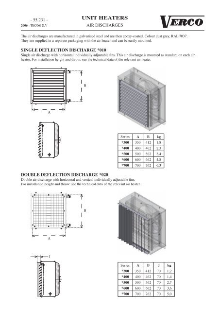
- 55.231 -2006 - TEC0612LV<strong>UNIT</strong> <strong>HEATERS</strong>AIR DISCHARGESThe air discharges are manufactured in galvanised steel and are then epoxy-coated. Colour dust grey, RAL 7037.They are supplied in a separate packaging with the air heater and can be easily mounted.SINGLE DEFLECTION DISCHARGE *010Single air discharge with horizontal individually adjustable fins. This air discharge is mounted as standard on each airheater. For installation height and throw: see the technical data of the relevant air heater.BASeriesA B kg*300 350 412 1,8*400 400 462 2,3*500 500 562 3,4*600 600 662 4,8*700 700 762 6,3DOUBLE DEFLECTION DISCHARGE *020Double air discharge with horizontal and vertical individually adjustable fins.For installation height and throw: see the technical data of the relevant air heater.BAJSeries A B J kg*300 350 412 70 1,2*400 400 462 70 1,4*500 500 562 70 2,7*600 600 662 70 3,6*700 700 762 70 5,0
- 55.232 -2006 - TEC0612LV<strong>UNIT</strong> <strong>HEATERS</strong>AIR DISCHARGESThe air discharges are manufactured in galvanised steel and are then epoxy-coated. Colour dust grey, RAL 7037.They are supplied in a separate packaging with the air heater and can be easily mounted.2 SIDE AIR DISCHARGE *030Air discharge for double air discharge outlet for ceiling mounting.Installation height: same as outlet *040.KABSeries A B K kg*300 410 350 115 4,6*400 460 400 165 6,0*500 560 500 165 8,0*600 660 600 165 10,1*700 760 700 165 12,44 SIDE AIR DISCHARGE *040Air discharge for outlet to 4 sides for ceiling mounting.For installation height : see the technical data of the relevant air heater.KABSeries A B K kg*300 410 350 115 4,5*400 460 400 165 5,9*500 560 500 165 7,8*600 660 600 165 9,8*700 760 700 165 12,1
- 55.233 -2006 - TEC0612LV<strong>UNIT</strong> <strong>HEATERS</strong>AIR DISCHARGESThe air discharges are manufactured in galvanised steel and are then epoxy-coated. Colour dust grey, RAL 7037.They are supplied in a separate packaging with the air heater and can be easily mounted.CONE DISCHARGE *050Air discharge for increased vertical air throw and mounting height.For installation height : see the technical data of the relevant air heater.AIGSeries A G I kg*400 420 250 300 4,9*500 520 300 300 6,2*600 620 350 300 7,6*700 720 400 300 8,7FISHTAIL DISCHARGE *060Air discharge for creating a horizontal air curtain.For installation height : see the technical data of the relevant air heater.DBACSeries A B C D kg*400 420 350 600 100 6,1*500 520 400 800 130 9,1*600 620 450 1000 160 12,5*700 720 500 1300 200 17,4
- 55.234 -2006 - TEC0612LV<strong>UNIT</strong> <strong>HEATERS</strong>AIR DISCHARGESThe air discharges are manufactured in natural profiled anodized aluminium.They are supplied in a separate packaging with the air heater and can be easily mounted.SECONDARY DEFLECTION DISCHARGE WALL MODEL *080Secondary air discharge for horizontal outlet, to increase the throw length by induction of the ambient air. The oppositeprofiled aluminium fins can be adjusted individually in order to set the induction ratio and the direction as required.The throw length is dependent on the setting.JBASeries A B J kg*400 500 460 135 4*500 600 560 135 6*600 700 660 135 8*700 800 760 135 10SECONDARY DEFLECTION DISCHARGE CEILING MODEL *090Secondary air discharge for vertical outlet, to increase the throw length by induction of the ambient air. The opposite profiledaluminium fins can be adjusted individually in order to set the induction ratio and the direction as required.The fins are pre-oriented to obtain a better spread at lower heights.JABSeries A B J kg*400 470 470 305 6*500 570 570 305 8*600 670 670 305 10*700 770 770 305 12
- 55.235 -2006 - TEC0612LV<strong>UNIT</strong> <strong>HEATERS</strong>AIR DISCHARGESThe air discharges are manufactured in galvanised steel and are then epoxy-coated. Colour dust grey, RAL 7037.They are supplied in a separate packaging with the air heater and can be easily mounted.INDUCTION FLOW DISCHARGE WALL MODEL *011Induction valves for horizontal or vertical outlet to increase the throw length through induction of the ambient air. The steelfins can be adjusted in 2 directions. Suitable for both wall mounting and ceiling mounting at greater heights.For installation height and throw: see the technical data of the relevant air heater.JBASeries A B J kg*400 500 460 120 7*500 600 560 120 9*600 700 660 120 11*700 800 760 120 13INDUCTION FLOW DISCHARGE CEILING MODEL *012Induction valves for vertical outlet to increase the destratification through induction of the ambient air. The steel fins areadjustable and are pre-oriented to obtain a better spread at lower heights.For installation height and throw: see the technical data of the relevant air heater.JABSeries A B J kg*400 500 460 305 8*500 600 560 250 11*600 700 660 320 15*700 800 760 280 18
- 55.251 -2006 - TEC0612LV<strong>UNIT</strong> <strong>HEATERS</strong>SUSPENSION BRACKETSThe supports are manufactured in galvanised steel and are then epoxy-coated. Colour dust grey, RAL 7037.WALL BRACKETConsists of 2 supports for both the suspension and /or support of the air heater.GFCEDBALL1TypeAC.4440.6AC.4440.7AC.4449Series L L1 A B C D E F G kg2300250600 6054,42400 /6400 3002500 /6500250 180 30 250 15 35 4002600 /6600 700 705500 5,12700 /6700 6001400 /34003001500 /3500 400800 805 400 270 65 270 60 35 121600 /3600 5001700 /3700 600WALL BRACKET lateralConsists of 2 supports for the lateral mounting of the air heater, for both the suspension and /or support of the air heater.Only for Series 2000 and 6000.GHFCABDELType Series L A B C D E F G H kgAC.4440.62300250235 4506002400 /6400 300 185 5004,4AC.4440.7 2500 /6500 700 250 180 30 400 15 250 185 600 5,1AC.4440.8 2600 /6600 800 500 185 700 5,8AC.4440.9 2700 /6700 900 600 185 800 6,4
- 55.252 -2006 - TEC0612LV<strong>UNIT</strong> <strong>HEATERS</strong>SUSPENSION BRACKETSThe supports are manufactured in galvanised steel and are then epoxy-coated. Colour dust grey, RAL 7037.WALL BRACKET prolongedConsists of 2 supports for mounting an air heater fitted with intake ducts.when ordering a Type Seriesmixing chambertype AK.*930 or AK.931LAC.4480.1 2400 /6400 620AC.4480.2 2500 /6500 670AC.4480.3 2600 /6600 760AC.4480.3 2700 /6700 760kg4,4Lmixing chambertype AK.*930 or AK.931AC.4489.1 1400 /3400 720AC.4489.2 1500 /3500 770AC.4489.3 1600 /3600 860AC.4489.3 1700 /3700 8604,6AK.*93*when ordering a Type Seriesmixing + filter chambertype AK.*930 or AK.931+ type AK.*910 or AK.911AC.4450.1 2400 /6400 1.000AC.4450.2 2500 /6500 1.050AC.4450.3 2600 /6600 1.140AC.4450.3 2700 /6700 1.140Lkg6,0Lmixing + filter chambertype AK.*930 or AK.931+ type AK.*910 or AK.911AC.4459.1 1400 /3400 1.100AC.4459.2 1500 /3500 1.150AC.4459.3 1600 /3600 1.240AC.4459.3 1700 /3700 1.2407,0AK.*91*AK.*93*Lwhen ordering a Type Series L kgfilter chamber AK.*910 or AK.911 AC.4450.1 2000 /6000 1.000 6,0filter chamberAK.*910 or AK.911AC.4459.1 1000 /3000 1.100 7,0AK.*91*
- 55.253 -2006 - TEC0612LV<strong>UNIT</strong> <strong>HEATERS</strong>SUSPENSION BRACKETSThe supports are manufactured in galvanised steel and are then epoxy-coated. Colour dust grey, RAL 7037.WALL BRACKET with plateConsists of 2 supports, 1 assembly plate, 4 M10 bolts and nuts for both suspension and /or support of the air heater.Only for Series 2000 and 6000.CKEDBAGHLL1Type Series L L1 A B C D E G H K kg2300250AC.4460.1600 610350 6,82400 /6400 300AC.4470.2 2500 /6500 700 710 270 180 40 250 15 400 450 265 8,2AC.4470.3 2600 /6600 500700 710650 9,52700 /6700 600CEILING BRACKET for horizontal air throwOne set comprises 2 reinforced steel suspension hooks, 2steel laths 600 mm long perforated every 50 mm with 12mm holes, 2 bent tacks, 4 M10 bolts and nuts.D1100L40AFTypeAC.4430AC.4439Series2300LMax.L1Min.A D F kg250 4502400 /6400 300 5002500 /6500 800 300 300 400 6002600 /6600 500 7002700 /6700 600 8001400 /3400300 5001500 /3500 400 600800 300 3001600 /3600 500 7001700 /3700 600 8005,25,2
- 55.254 -2006 - TEC0612LV<strong>UNIT</strong> <strong>HEATERS</strong>SUSPENSION BRACKETSThe supports are manufactured in galvanised steel and are then epoxy-coated. Colour dust grey, RAL 7037.CEILING BRACKET at 4 pointsOne set comprises 4 reinforced steel suspension hooks, 4 steel laths 600 mm long perforated every 50 mm with 12 mmholes, 4 M10 bolts and nuts.F1100L295TypeAC.4420Series300LMax.LMin.F300 450400 500 500500 602 350 600600 400 700700 400 800kg5,0110015050252550255025O1240CEILING BRACKET at 2 pointsOne set comprises 2 reinforced steel suspension hooks, 4 steel laths 600 mm long perforated every 50 mm with 12 mmholes, 2 M10 bolts and nuts.1100FL295TypeAC.4410SeriesLMax.LMin.F300 585 300 450400 579 300 500500 562 350 600600 539 400 700700 510 400 800kg4,4
- 55.271 -2006 - TEC0612LV<strong>UNIT</strong> <strong>HEATERS</strong>AIR BOXESFor its various types of air heaters Verco has developed a range of air mixing boxes, suction boxes and ducts. All parts aremanufactured in sendzimir galvanized steel sheet. They are all epoxy-coated in dust grey RAL 7037.The parts are supplied in separate packaging and are easy to mount on the air heater. The necessary nuts and bolts are alsosupplied.All the various suction accessories have a flange connection on both sides for easy mounting.When using air mixing boxes and ducts you must take into account the air flow and output reduction, for these values werefer to the technical data.Type determinationAK.4830830 = type of intake duct4 = sizeK = intake ductA = air heaterTypeAK.*810AK.*820AK.*830AK.*840AK.*850AK.*860AK.*879AK.*880AK.*890AK.*891DescriptionSuction chamberdouble air mixing chambermixing chamber for inside and fresh airsuction chamber for inside airsuction chamber for outside aircorner connectionrain hoodductflexible connection squareflexible connection rectangularTypeAK.*910AK.*911AK.*920AK.*930AK.*931AK.*940AK.*950AK.*960AK.499Descriptionfilter with chamber squarefilter with chamber rectangularfreh air wall grillemixing chambermixing chamberguard grille and servo motorspare air filterductflange connectionEXAMPLES OF COMBINATION POSSIBILITIESWall mounting*810*890*810*910*880*880*911*940*840*840
- 55.272 -2006 - TEC0612LV<strong>UNIT</strong> <strong>HEATERS</strong>AIR BOXESCeiling mounting with mixing chamber*910 *930*850*920*920*880*931*911 *960*891*920*911*891*931*960*891*920*820*930*920*880*891*840
- 55.273 -2006 - TEC0612LV<strong>UNIT</strong> <strong>HEATERS</strong>AIR BOXESCeiling mounting with mixing chamber*810*879*891*880*960*911*911*891*920*931*830*860*880*879*931*891*960*920*960*880Ceiling mounting*940*910*931
- 55.274 -2006 - TEC0612LV<strong>UNIT</strong> <strong>HEATERS</strong>AIR BOXESDIMENSIONSEKDDHMLBAK.*830AK.*840AK.*810DDEDEOOOODDAK.*940AK.*850NAK.*860OEDAK.*920AK.*890EAK.*891EED D+42E+42DED200AK.*910VAK.*911VEAK.*960D
- 55.275 -2006 - TEC0612LV<strong>UNIT</strong> <strong>HEATERS</strong>AIR BOXESED40ED40AK.*880AALAK.*930AK.*931EDDEAK.*879RSTFQPDD+200EE+200AK.*820MESURES (mm)Series A B C D E F G H I K L4 310 575350 450 1.150 325 5255255 360 675 450 550 1.450 425 625 625100250 1506 450 775 550 650 1.450 375 725 7257 450 875 650 750 1.450 325 825 825Series M N O P Q R S T U V4 350 600 500750 850 250 8505 450 700 600 780 950 280 9505006 550 800 700 810 1.050 310 1.050100 3807 650 900 800 840 1.150 340 1.150
- 55.276 - <strong>UNIT</strong> <strong>HEATERS</strong>2006 - TEC0612LV
- 55.301 -2006 - TEC0612LV<strong>UNIT</strong> <strong>HEATERS</strong>ELECTRICAL CONNECTION MOTOR TYPE 11electrical connection motor 11 :2 speed - 1 x 230 VMotor with external rotor & operating capacitor;Alternating current 1 x 230 V; 50 Hz;Motor insulation class: F;Motor protection class: IP 54;2 speed by branched windingM1U1 Z2 U2 TK TKThe motor windings are equipped with thermal contacts. Thermal contacts are temperature sensing, switching elementsbuilt directly into the windings of the external rotor windings. They interrupt an electrical contact as soon as the maximumadmissible sustained temperature, 130°C, has been reached. The thermal contact protects the air heater against overloadingin accordance with specification VDE 0730.Breaking capacity : 10 A with cos phi =1.0; 6A with cos phi = 0.6Rated voltage: 250 VoltsThe thermal contacts must be connected to the control circuit of the main contactor to prevent automatic reconnection ofthe motor to the mains in the event of a fault.Rotation direction: the motor rotates clockwise when the air flows out of the air diffuser. The direction of rotation cannot bechanged.Connection test: compare the current intensity at all speeds with the label on the air heater.high speedCU1 Z2 U2 TK TKZ2U1U2TK TKLNLN TK TKlow speedCU1 Z2 U2 TK TKZ2U1U2TK TKLNL NTK TKConnection of a 2 speed switch5+1 wires are necessaryDifferent air heaters of the same size can be connected inparallel. Air heaters of different sizes cannot be connected inparallel to a 2 speed switch.Thermal contacts must be connected in series.Do not build bridges in the terminal boxes.See also specific manual of the speed controls.U1 Z2 U2 TK TKU1 Z2 U2 TK TK
- 55.303 -2006 - TEC0612LV<strong>UNIT</strong> <strong>HEATERS</strong>ELECTRICAL CONNECTION MOTOR TYPE 14electrical connection motor 14 :3 speed- 3 x 400 VM3Motor with external rotor & operating capacitor;Alternating current 3 x 400 V; 50 Hz;Motor insulation class: F;Motor protection class: IP 54;No inversion of the tension;3 speed by ΔΔ / YY / Δ - inversionV3 U3 W3 W1 V1U1W2 V2 U2 TK TKThe motor windings are equipped with thermal contacts. Thermal contacts are temperature sensing, switching elementsbuilt directly into the windings of the external rotor windings. They interrupt an electrical contact as soon as the maximumadmissible sustained temperature, 130°C, has been reached. The thermal contact protects the air heater against overloadingin accordance with specification VDE 0730.Breaking capacity: 10A with cos phi =1.0; 6A with cos phi = 0.6Rated voltage: 250 VoltsThe thermal contacts must be connected to the control circuit of the main contactor to prevent automatic reconnection ofthe motor to the mains in the event of a fault.Rotation direction: the motor has the right direction of rotation when the air flows out of the air diffuser. The direction ofrotation can be changed by inversion of the 2 phases.Connection test: compare the current intensity at all speeds with the label on the air heater.high speedL2U3V1V2V3 U3 W3 W1 V1U1W2 V2 U2 TK TKU2L1W3U1V3W1L3W2TK TKmedium speedL3 L2L1TK TKL1U2V1L2U1V2V3 U3 W3 W1 V1U1W2 V2 U2 TK TKW3W2W1TK TKL3L3 L2L1TK TKlow speedL1U2U3V1V3U3 V3 V3 U3 W3 W1 V1 W2 V2 U2 TK TKV3 U3 W3 W1 V1U1W2 V2 U2 TK TKL2U1W2 W3 W1V2L3TK TKConnection of a 3 speed switch11+1 wires are necessaryDifferent air heaters of the same size can be connected inparallel. Thermal contacts must be connected in series.Do not build bridges in the terminal boxes.In position 1 the sequence of the network must be L3 L2 L1,otherwise the rotation direction is incorrect.L3 L1U1V3 U3 W3 W1 V1 U1L2W2 V2 U2 TK TKTK TKSee also specific manual of the speed controls.
- 55.304 -2006 - TEC0612LV<strong>UNIT</strong> <strong>HEATERS</strong>ELECTRICAL CONNECTION MOTOR TYPE 16electrical connection motor 16 :Eex(e) - 2-speed - 3 x 400 VMotor with external rotor & operating capacitor;Alternating current 3 x 400 V; 50 Hz;Motor insulation class: F;Motor protection class: IP 44;No inversion of the tension;3 speed by Y / Δ - inversionAccording to standards EN 50 014 and EN 50 019.M3U1 V1 W1 U2 V2W2 K KThe motor with increased security “e” can be installed in rooms with a risk of explosion in the range of zone 1 and 2.The motor bears distinguishing mark: Eexe II T3 PTB 01 ATEK 3349Temperature class: T1, T2 or T3Motor protection: protection achieved with a built-in temperature sensitive resistance (PTC). This PTC, connected to a set ofmotor protections, protects the motor in Ex range to PTB 3.53 PTC/A. Other protections, such as thermal motor protections,are not allowed.The PTC must be connected to an individual cable, equipped with 2 protected wires. Only 2 air heaters can be connected tothe motor protection set.Rotation direction: the motor has the right direction of rotation when the air flows out of the air diffuser. The direction ofrotation can be changed by inversion of the 2 phases.Connection test: compare the current intensity at all speeds with the label on the air heater.high speedL1W2U1U1 V1 W1 U2 V2 W2 K KW1U2L3V2 V1L2K KL1 L2 L3K Klow speedL1L2U1U2V2W2V1U1 V1 W1 U2 V2 W2 K KW1L3K KL1 L2 L3K KConnection of a 2 speed switch1 cable with 6+1 wires for the motor and a protected cablewith 2 wires for the PTC are required.Only 2 air heaters, of different sizes, can be connected inparallel.PTC must be connected in series.Do not build bridges in the terminal boxes.The speed switch must not be installed in a room wherethere is a risk of explosion.U1 V1 W1 U2 V2 W2 K KU1 V1 W1 U2 V2 W2 K K
- 55.311 -2006 - TEC0612LV<strong>UNIT</strong> <strong>HEATERS</strong>SPEED CONTROLS : SC.122.0002-speed switchfor 1 phase motorsGeneral Description• The control units are intended for speed change-over of one or multiple 1-phase motors via the integrated switch. Themaximum total current of all motors must not exceed the rated current of the device.• Motor protection function through connection of thermocontacts (not suitable for PTC resistors). The device stops whenthe thermocontacts are released. Reactivation occurs after cooling the drive by disconnecting and reconnecting the mainsvoltage (after approx. 2 minutes) or by means of the switch. Caution! When multiple motors are connected: Connect thethermocontacts in series to terminals TK-TK.• Remote control (ON/OFF) at the preselected speed via a potential-free contact (terminals RT-RT). The operating status lampdoes not go out after this deactivation!• Additional status signal contacts:- Potential-free change-over contact element (Terminals 11, 12, 14) 250V AC /2A- switched to 230V and constant voltage max. 1A (in switch position “0” also).• Automatic reconnection after mains failure.• Integrated operating status lamp and fuse.Technical Data• Mains voltage 1x230 V, 50Hz (-15% / +10%)• Max. Motor output 4 kW• Max. 10 A fuse• Internal control fuse F2A (5x20 mm)• Max. Ambient temperature +40°C• Protection class IP 54, ABS plastic housing• Weight approx. 1.1 kg250Terminal connecting planSC.122.000205 115L N TK TK U1 U2 Z2 Fs Fs RT RT N L1 N ATK U1 U2 Z2!230V ACoperating statuslamp1x230Valarm lamp1x230VTKMotor 1with integrated thermocontactsL1 PE N1 x 230 V + N50 Hzon / off
- 55.312 -2006 - TEC0612LV<strong>UNIT</strong> <strong>HEATERS</strong>SPEED CONTROLS : SC.122.0102- speed switch with 1 potentiometer and 1 remote temperature indicatorfor 1 phase motorsGeneral Description• The control units are intended for speed change-over of one or multiple 1-phase motors via the integrated switch. Themaximum total current of all motors must not exceed the rated current of the device.• On/Off control occurs at the preselected speed via the integrated room thermostat with a potentiometer on its cover.Temperature range 5-30°C. The switch can be deactivated by remote control (potential free contact ECL-ECL)• Motor protection function through connection of thermocontacts (not suitable for PTC resistors). The device stops whenthe thermocontacts are released. Reactivation occurs after cooling the drive by disconnecting and reconnecting the mainsvoltage (after approx. 2 minutes) or by means of the switch. Caution! When multiple motors are connected: Connect thethermocontacts in series to terminals TK-TK• Additional status signal contacts:- Potential-free change-over contact element 230V Max. 1A- switched to 230V and constant voltage max. 1A• Integrated operating status lamp (Green: active – Red: inactive) and fuse.Technical Data• Mains voltage 1x230 V, 50Hz (-15% / +10%)• Max. Motor output 4 kW• Max. 10 A fuse• Internal control fuse F2A (5x20 mm)• Max. Ambient temperature +40°C• Protection class IP 54, ABS plastic housing• Weight approx. 1.1 kg315Terminal connecting planSC.122.010205135L N TK TK U1 U2 Z2 Fs Fs RT RT N L1 N ATK U1 U2 Z2!230V ACoperating statuslamp1x230Valarm lamp1x230VTKMotor 1with integrated thermocontactsL1 PEN1 x 230 V + N50 Hzon / offsensor
- 55.313 -2006 - TEC0612LV<strong>UNIT</strong> <strong>HEATERS</strong>SPEED CONTROLS : SC.122.0202- speed switch with 2 potentiometer,1 remote temperature indicator and 1 relay for externalclock for 1 phase motorsGeneral Description• The control units are intended for speed change-over of one or multiple 1-phase motors via the integrated switch. Themaximum total current of all motors must not exceed the rated current of the device.• On/Off control occurs at the preselected speed via the integrated room thermostat with a potentiometer (day and nighttemperature) on its cover. Temperature range 5-30°C. The switch can be deactivated by remote control (potential freecontact ECL-ECL) to switch between the two potentiometers.• Motor protection function through connection of thermocontacts (not suitable for PTC resistors). The device stops whenthe thermocontacts are released. Reactivation occurs after cooling the drive by disconnecting and reconnecting the mainsvoltage (after approx. 2 minutes) or by means of the switch. Caution! When multiple motors are connected: Connect thethermocontacts in series to terminals TK-TK• Additional status signal contacts:- Potential-free change-over contact element 230V Max. 1A- switched to 230V and constant voltage max. 1A• Integrated operating status lamp (Green: active – Red: inactive) and fuse.Technical Data• Mains voltage 1x230 V, 50Hz (-15% / +10%)• Max. Motor output 4 kW• Max. 10 A fuse• Internal control fuse F2A (5x20 mm)• Max. Ambient temperature +40°C• Protection class IP 54, ABS plastic housingTerminal connecting planSC.122.020L N TK TK U1 U2 Z2 Fs Fs RT RT N L1 N ATK U1 U2 Z2!230V ACoperating statuslamp1x230Valarm lamp1x230VTKMotor 1with integrated thermocontactsL1 PE N1 x 230 V + N50 Hzon / offsensor
- 55.314 -2006 - TEC0612LV<strong>UNIT</strong> <strong>HEATERS</strong>SPEED CONTROLS : SC.122.1002- speed switch with hour and week programfor 1 phase motorsGeneral Description• The control units are intended for speed change-over of one or multiple 1-phase motors via the integrated switch. Themaximum total current of all motors must not exceed the rated current of the device.• Remote control (ON/OFF) at the preselected speed via potential free contact (terminals T11-T12 for night thermostat;terminals T21-T22 for the day thermostat). You can switch between the two thermostats via the integrated timer with weekprogramme.• Motor protection function through connection of thermocontacts (not suitable for PTC resistors). The device stops whenthe thermocontacts are released. Reactivation occurs after cooling the drive by disconnecting and reconnecting the mainsvoltage (after approx. 2 minutes) or by means of the switch. Caution! When multiple motors are connected: Connect thethermocontacts in series to terminals TK-TK .• Additional status signal contacts:- Potential-free change-over contact element 230V Max. 1A- switched to 230V and constant voltage max. 1A• Integrated operating status lamp (Green: active – Red: inactive) and fuse.Technical Data• Mains voltage 1x230 V, 50Hz (-15% / +10%)• Max. Motor output 4 kW• Max. 10 A fuse• Internal control fuse F2A (5x20 mm)• Max. Ambient temperature +40°C• Protection class IP 54, ABS plastic housing315205135Terminal connecting planSC.122.100L N TK TK U1 U2 Z2 Fs Fs T11 T12 T21 T22 N L1 N ATK U1 U2 Z2!230V ACoperating statuslamp1x230Valarm lamp1x230VTKMotor 1with integrated thermocontactsL1 PEN1 x 230 V + N50 HzInputnightInputdaysensor
- 55.315 -2006 - TEC0612LV<strong>UNIT</strong> <strong>HEATERS</strong>SPEED CONTROLS : SC.122.1202- speed switch with clock and 2 potentiometersand 1 remote temperature indicatorfor 1 phase motorsGeneral Description• The control units are intended for speed change-over of one or multiple 1-phase motors via the integrated switch. Themaximum total current of all motors must not exceed the rated current of the device.• On/Off control occurs at the preselected speed via the integrated room thermostat with a potentiometer (day and nighttemperature) on its cover. Temperature range 5-30°C. You can switch between the two thermostats via the integrated timerwith week programme.• Motor protection function through connection of thermocontacts (not suitable for PTC resistors). The device stops whenthe thermocontacts are released. Reactivation occurs after cooling the drive by disconnecting and reconnecting the mainsvoltage (after approx. 2 minutes) or by means of the switch. Caution! When multiple motors are connected: Connect thethermocontacts in series to terminals TK-TK• Additional status signal contacts:- Potential-free change-over contact element 230V Max. 1A- switched to 230V and constant voltage max. 1A• Integrated operating status lamp (Green: active – Red: inactive) and fuse.Technical Data• Mains voltage 1x230 V, 50Hz (-15% / +10%)• Max. Motor output 4 kW• Max. 10 A fuse• Internal control fuse F2A (5x20 mm)• Max. Ambient temperature +40°C• Protection class IP 54, ABS plastic housing315Terminal connecting planSC.122.120205135L N TK TK U1 U2 Z2 Fs Fs N L1 N ATK U1 U2 Z2!230V ACoperating statuslamp1x230Valarm lamp1x230VTKMotor 1with integrated thermocontactsL1 PE N1 x 230 V + N50 Hzsensor
- 55.316 -2006 - TEC0612LV<strong>UNIT</strong> <strong>HEATERS</strong>SPEED CONTROLS : SC.123.XXX5-step transformer regulator without relay for thermocontactfor 1 phase motorsGeneral Description• The transformer induced control units are suitable for the speed control of voltage controllable 1-ventilators.• The speeds are set manually by means of the integrated 5 step switch. The maximum total current of all motors must notexceed the rated current (I) of the device.• Additional voltage output 230 V (terminals 1 and 2) is connected when the ventilator operates in steps 1, 2, 3, 4 or 5 andcan be used e.g. for an indicator light or for flap control (max. contact load 1 A).• Integrated operating status lamp.• Automatic reactivation after mains failure.Technical Data• Mains voltage: 1 x 230 V (-15% / +10%), 50/60 Hz• Max. permissible ambient temperature: 40°C• Housing protection class: IP 54• The output voltages can be set by means of a 5 step switch (90V – 110V – 140 V – 180 V – 230 V).Terminal connecting planN L1 U1 U2 1 2LN230V ACmax. 1Acontact loadPE N L11x230V50 /60 HzMains voltagePE U1 U2M1without thermocontact
- 55.317 -2006 - TEC0612LV<strong>UNIT</strong> <strong>HEATERS</strong>SPEED CONTROLS : SC.124.XXX5-step transformer regulator with relay for thermocontactfor 1 phase motorsGeneral Description• The transformer induced control units are suitable for the speed control of voltage controllable 1-ventilators.• The speeds are set manually by means of the integrated 5 step switch. The maximum total current of all motors must notexceed the rated current (I) of the device.• Motor protection function through connection of thermocontacts (not suitable for PTC resistors). The device stops whenthe thermocontacts are released. Reactivation occurs after cooling the drive by disconnecting and reconnecting the mainsvoltage (after approx. 2 minutes) or by means of the switch. Caution! When multiple motors are connected: Connect thethermocontacts in series to terminals “5” + “5” or TK-TK• Remote control (ON/OFF) at the preselected speed via a potential-free contact (terminals “6” – “7” or RT-RT). Theoperating status lamp does not go out after this deactivation!• Disconnection with locking e.g. for antifrost thermostat (Reactivation occurs in the same way as after a motor failure) viaintegration in the TK connector (circuit design).• Additional status signal contacts:- Potential-free change-over contact element (Terminals 11, 12, 14) 250 V AC / 2A- 30 V switched and constant voltage max. 1 A. (in switch position “0” also), Terminals 1, 2, 3- Integrated operating status lamp• Automatic reactivation after mains failure.Technical Data• Mains voltage : 1 x 230 V (-15% / +10%), 50/60 Hz • Max. permissible ambient temperature : 40°C• The output can be set by means of a 5 step switch (90V – 110V – 140 V – 180 V – 230 V).Typenominal current(A)max. ratedcurrent (A)max. powerdissipationweight(kg)protectionclassdimensionsconnectionplanSC.124.020 2,0 T4 25 2,3 IP54 A 1SC.124.035 3,5 T4 35 3,6 IP54 A 1SC.124.060 6,0 T8 40 5,1 IP54 A 1SC.124.075 7,5 T8 45 6,1 IP54 B 1SC.124.140 14,0 T20 110 12,6 IP54 C 2DimensionsC2702531631462,5A1156114,59230195166118216724022313211532842256032324015B325,518613
- 55.318 -2006 - TEC0612LV<strong>UNIT</strong> <strong>HEATERS</strong>SPEED CONTROLS : SC.124.XXXTerminal connecting plan1N L1 U1 U2 1 2 3 4 5 6 7 12 11 14N L L1* 1*230V ACmax. 1A230V AC250V ACmax. 2A0 1PE N L11x230V50 /60 HzPE U1 U2M1TKTKJ212 11 14 N L L RT RT FS FS TK TK N L U1 U21* 1* 1*250V ACmax. 2A230V ACmax. 1A230V AC0 1PE N L1x230V50 /60 HzPE U1U2M1TKTK
- 55.331 -2006 - TEC0612LV<strong>UNIT</strong> <strong>HEATERS</strong>SPEED CONTROLS : SC.134.0002-speed switch for 3 phase motorsGeneral Description• The control units are intended for speed change-over of one or multiple three-phase motors via the integrated switch. Themaximum total current of all motors must not exceed the rated current of the device.• Integrated operating status lamp and fuse.• Motor protection function through connection of thermocontacts (not suitable for PTC resistors). The device stops whenthe thermocontacts are released. Reactivation occurs after cooling the drive by disconnecting and reconnecting the mainsvoltage (after approx. 2 minutes) or by means of the switch. Caution! When multiple motors are connected: Connect thethermocontacts in series to terminals “5” + “5” or TK-TK• Automatic reconnection after mains failure.• Remote control (ON/OFF) at the preselected speed via a potential-free contact (terminals “6” – “7” or RT-RT). The operatingstatus lamp does not go out after this deactivation!• Additional status signal contacts:- Potential-free change-over contact element (Terminals 11, 12, 14) 250V AC /2A- switched to 230V and constant voltage max. 1A (in switch position “0” also).Technical Data• Mains voltage 3x400 V, 50Hz (-15% / +10%)• Max. Motor output 4 kW• Max. 10 A fuse• Internal control fuse F2A (5x20 mm)• Max. Ambient temperature +40°C• Protection class IP 54, ABS plastic housing• Weight approx. 1.1 kgDimensions2301951156114,59166128,5Terminal connecting planSC.134.000F2A (Ø 5x20 mm)L1 L2 L3 N N TK TK U1 V1 W1 U2 V2 W2 J J RT RT N L L 11 12 14!230V ACTKTKU1 V1 W1U2 V2 W2contact loadmax. 230VAC /1Acontact loadmax. 250VAC /2AL1 L2 L3 PE N3 x 400 V + N50 HzMotor 3with integrated thermocontactson / off
- 55.332 -2006 - TEC0612LV<strong>UNIT</strong> <strong>HEATERS</strong>SPEED CONTROLS : SC.134.0102-speed switch with 1 potentiometer and 1 remote temperature indicatorfor 3 phase motorsGeneral Description• The control units are intended for speed change-over of one or multiple three-phase motors via the integrated switch. Themaximum total current of all motors must not exceed the rated current of the device.• On/Off control occurs at the preselected speed via the integrated room thermostat with a potentiometer on its cover.Temperature range 5-30°C. The switch can be deactivated by remote control (potential free contact ECL-ECL)• Integrated operating status lamp (Green: active – Red: inactive) and fuse.• Motor protection function through connection of thermocontacts (not suitable for PTC resistors). The device stops whenthe thermocontacts are released. Reactivation occurs after cooling the drive by disconnecting and reconnecting the mainsvoltage (after approx. 2 minutes) or by means of the switch. Caution! When multiple motors are connected: Connect thethermocontacts in series to terminals “TK” –“TK”.• Additional status signal contacts:- Potential-free change-over contact element 230V Max. 1A- switched to 230V and constant voltage max. 1ATechnical Data• Mains voltage 3x400 V, 50Hz (-15% / +10%)• Max. Motor output 4 kW• Max. 10 A fuse• Internal control fuse F2A (5x20 mm)• Max. Ambient temperature +40°C• Protection class IP 54, ABS plastic housing315Terminal connecting planSC.134.010205135L1 L2 L3 N TK TK U1 V1 W1 U2 V2 W2 Fs Fs RT RT N L1 N ATKU1 V1 W1!230V ACoperating statuslamp1x230Valarm lamp1x230VTKU2 V2 W2L1 L2 L3 PE N3 x 400 V + N50 HzMotor 3with integrated thermocontactson / offsensor
- 55.333 -2006 - TEC0612LV<strong>UNIT</strong> <strong>HEATERS</strong>SPEED CONTROLS : SC.134.0202-speed switch with 2 potentiometers, 1 remote temperature indicatorand 1 relay for external clockfor 3 phase motorsGeneral Description• The control units are intended for speed change-over of one or multiple three-phase motors via the integrated switch. Themaximum total current of all motors must not exceed the rated current of the device.• On/Off control occurs at the preselected speed via the integrated room thermostat with a potentiometer (day and nighttemperature) on its cover. Temperature range 5-30°C. The switch can be deactivated by remote control (potential freecontact ECL-ECL) to switch between the two potentiometers.• Integrated operating status lamp (Green: active – Red: inactive) and fuse.• Motor protection function through connection of thermocontacts (not suitable for PTC resistors). The device stops whenthe thermocontacts are released. Reactivation occurs after cooling the drive by disconnecting and reconnecting the mainsvoltage (after approx. 2 minutes) or by means of the switch. Caution! When multiple motors are connected: Connect thethermocontacts in series to terminals ”TK”-“TK”• Additional status signal contacts:- Potential-free change-over contact element 230V Max. 1A- switched to 230V and constant voltage max. 1ATechnical Data• Mains voltage 3x400 V, 50Hz (-15% / +10%)• Max. Motor output 4 kW• Max. 10 A fuse• Internal control fuse F2A (5x20 mm)• Max. Ambient temperature +40°C• Protection class IP 54, ABS plastic housingTerminal connecting planSC.134.020L1 L2 L3 N TK TK U1 V1 W1 U2 V2 W2 Fs Fs RT RT N L1 N ATKU1 V1 W1!230V ACoperating statuslamp1x230Valarm lamp1x230VTKU2 V2 W2L1 L2 L3 PE N3 x 400 V + N50 HzMotor 3with integrated thermocontactson / offsensor
- 55.334 -2006 - TEC0612LV<strong>UNIT</strong> <strong>HEATERS</strong>SPEED CONTROLS : SC.134.1002-speed switch with hour and week programfor 3 phase motorsGeneral Description• The control units are intended for speed change-over of one or multiple three-phase motors via the integrated switch. Themaximum total current of all motors must not exceed the rated current of the device.• Remote control (ON/OFF) at the preselected speed via potential free contact (terminals “T11”-“T12” for night thermostat;terminals T21-T22 for the day thermostat. You can switch between the two thermostats via the integrated timer with weekprogramme.• Integrated operating status lamp (Green: active – Red: inactive) and fuse.• Motor protection function through connection of thermocontacts (not suitable for PTC resistors). The device stops whenthe thermocontacts are released. Reactivation occurs after cooling the drive by disconnecting and reconnecting the mainsvoltage (after approx. 2 minutes) or by means of the switch. Caution! When multiple motors are connected: Connect thethermocontacts in series to terminals “TK”-“TK”• Additional status signal contacts:- Potential-free change-over contact element 230V Max. 1A- switched to 230V and constant voltage max. 1ATechnical Data• Mains voltage 3x400 V, 50Hz (-15% / +10%)• Max. Motor output 4 kW• Max. 10 A fuse• Internal control fuse F2A (5x20 mm)• Max. Ambient temperature +40°C• Protection class IP 54, ABS plastic housing315205135Terminal connecting planSC.134.100L1 L2 L3 N TK TK U1 V1 W1 U2 V2 W2 Fs Fs T11 T12 T21 T22 N L1 N ATKU1 V1 W1!230V ACoperating statuslamp1x230Valarm lamp1x230VTKU2 V2 W2L1 L2 L3 PE N3 x 400 V + N50 HzMotor 3with integrated thermocontactsInputnightInputday
- 55.335 -2006 - TEC0612LV<strong>UNIT</strong> <strong>HEATERS</strong>SPEED CONTROLS : SC.134.1202-speed switch with clock and 2 potentiometers and 1 remote temperature indicatorfor 3 phase motorsGeneral Description• The control units are intended for speed change-over of one or multiple three-phase motors via the integrated switch. Themaximum total current of all motors must not exceed the rated current of the device.• On/Off control occurs at the preselected speed via the integrated room thermostat with a potentiometer (day and nighttemperature) on its cover. Temperature range 5-30°C. You can switch between the two thermostats via the integrated timerwith week programme.• Integrated operating status lamp (Green: active – Red: inactive) and fuse.• Motor protection function through connection of thermocontacts (not suitable for PTC resistors). The device stops whenthe thermocontacts are released. Reactivation occurs after cooling the drive by disconnecting and reconnecting the mainsvoltage (after approx. 2 minutes) or by means of the switch. Caution! When multiple motors are connected: Connect thethermocontacts in series to terminals “TK”-“TK”• Additional status signal contacts:- Potential-free change-over contact element 230V Max. 1A- switched to 230V and constant voltage Max. 1ATechnical Data• Mains voltage 3x400 V, 50Hz (-15% / +10%)• Max. Motor output 4 kW• Max. 10 A fuse• Internal control fuse F2A (5x20 mm)• Max. Ambient temperature +40°C• Protection class IP 54, ABS plastic housing315Terminal connecting planSC.134.120205135L1 L2 L3 N TK TK U1 V1 W1 U2 V2 W2 Fs Fs N L1 N ATKU1 V1 W1!230V ACoperating statuslamp1x230Valarm lamp1x230VTKU2 V2 W2L1 L2 L3 PE N3 x 400 V + N50 HzMotor 3with integrated thermocontactssensor
- 55.336 -2006 - TEC0612LV<strong>UNIT</strong> <strong>HEATERS</strong>SPEED CONTROLS : SC.136.XXX5-step transformer regulator with relay for thermocontact and thermostatfor 3 phase motorsGeneral Description• The transformer induced control units are suitable for the speed control of voltage controllable 3-ventilators.• The speeds are set manually by means of the integrated 5 step switch. The maximum total current of all motors must notexceed the rated current (I) of the device.• Motor protection function through connection of thermocontacts (not suitable for PTC resistors). The device stops whenthe thermocontacts are released. Reactivation occurs after cooling the drive by disconnecting and reconnecting the mainsvoltage (after approx. 2 minutes) or by means of the switch. Caution! When multiple motors are connected: Connect thethermocontacts in series to terminals TK-TK• Remote control (ON/OFF) at the preselected speed via a potential-free contact (terminals RT-RT). The operating status lampdoes not go out after this deactivation!• Disconnection with locking e.g. for antifrost thermostat (Reactivation occurs in the same way as after a motor failure) viathe potential-free contact (terminals FS-FS).• Additional status signal contacts:- Potential-free change-over contact element (Terminals 11, 12, 14) 250 V AC / 2A- 230 V switched and constant voltage max. 1 A. (in switch position “0” also)• Integrated operating status lamp• Automatic reactivation after mains failure.Technical Data• Mains voltage : 3 x 400 V (-15% / +10%), 50/60 Hz• Max. Permissible ambient temperature : 40°C• Protection class IP 54• The output voltages can be set by means of a 5-step switch (95 V – 145 V – 190 V – 240 V – 400 V)terminal connecting planSC.136.xxx12 11 14 N L L RT RT FS FS TK TK NL1 L2 L3U1 V1 W1250V ACmax. 2Acontact load230V ACmax. 1A230V AC1 20 1TK U1 V1 W1ON / OFFON / OFF(only with reset)PE NL1 L2 L33 x 400 V + N50 HzTK U2 V2 W2Motor 3with integrated thermocontacts
- 55.351 -2006 - TEC0612LV<strong>UNIT</strong> <strong>HEATERS</strong>SPEED CONTROLS : SERVO MECHANISMSExamples for the connection of servo mechanismsThe different types of servo mechanisms are controlled via the potential-free contact or via the 230 V contacts of theoperating status relay. This relay is activated when the device is switched on and the ventilator operates. During remotecontrol deactivation via terminals “6” – “7” or RT-RT in the event of motor failure (disconnection of thermocontactterminal connectors “4” and “5”) or TK-TK the relay is deactivated. Forservo mechanisms with “1-speed control” constantvoltage connection (in switch position “0” also) for “Flap closed”.1. For motors with “1-wire control”a. Flap “OPEN” : when the ventilator operates, 230 V, on terminalLb. Flap “CLOSED” : contant voltage on terminal L, when the ventilator is off (in switch position “0” also)2. For motors with “spring return”a. Flap “OPEN” : when the ventilator operates, 230 V, on terminalb. Flap “CLOSED” : spring force (if no voltage is connected)L3. For motors with “2-wire control”La. Flap “OPEN” : when the ventilator operates, voltage on terminal14b. Flap “CLOSED” : voltage on terminal 12, when the ventilator is off (in switch position “0” also)AC230VAC230V1 2 3N L LN L LN 11 12 14AC24V...250VMMM