Service manual and spare parts list - BUKH Bremen
Service manual and spare parts list - BUKH Bremen
Service manual and spare parts list - BUKH Bremen

Create successful ePaper yourself
Turn your PDF publications into a flip-book with our unique Google optimized e-Paper software.
2.6 Connection of gearbox with<br />
propeller<br />
We recommend a flexible connection<br />
between the gearbox <strong>and</strong> the propeller<br />
shaft, when the engine is flexibly<br />
mounted, in order to compensate for<br />
angular deflections. The installation of a<br />
special propeller thrust bearing is not<br />
required, since the propeller thrust will<br />
be taken by the transmission bearing,<br />
provided the value specified under<br />
«Technical data», item 1.2, is not exceeded.<br />
However, the output shaft<br />
should be protected from additional<br />
loads. Special care should be taken to<br />
prevent torsional vibration. When using<br />
a universal joint shaft, make certain to<br />
observe the manufacturer’s instructions.<br />
2.7 Suspension of engine–gearbox<br />
assembly in the boat<br />
Special care should be taken to protect<br />
the gearbox from detrimental stresses<br />
<strong>and</strong> loads when the engine-transmission<br />
assembly is not elastically suspended in<br />
the boat or craft.<br />
The gearbox should be conveniently accessible<br />
for maintenance. If the oil drain<br />
plug of the gearbox is not accessible, the<br />
oil will have to be sucked off.<br />
Fig. 13<br />
Manual <strong>and</strong> Spare Parts List ZF M line<br />
20°<br />
2.8 Position of gearbox<br />
in the boat<br />
The inclination of the gearbox unit in the<br />
direction of the shafts should not exceed<br />
an installation angle of 20 degrees (see<br />
Fig.13) <strong>and</strong> 15° for ZF 15 MIV.<br />
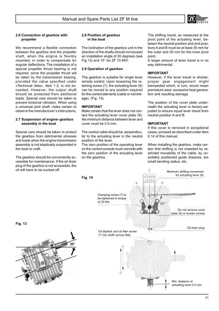
2.9 Operation of gearbox<br />
The gearbox is suitable for single lever<br />
remote control. Upon loosening the retaining<br />
screw (7), the actuating lever (6)<br />
can be moved to any position required<br />
for the control elements (cable or rod linkage).<br />
(Fig. 14).<br />
IMPORTANT<br />
Make certain that the lever does not contact<br />
the actuating lever cover plate (9):<br />
the minimum distance between lever <strong>and</strong><br />
cover must be 0.5 mm.<br />
The control cable should be perpendicular<br />
to the actuating lever in the neutral<br />
position of the lever.<br />
The zero position of the operating lever<br />
on the control console must coincide with<br />
the zero position of the actuating lever<br />
on the gearbox.<br />
Fig. 14<br />
be tightened to torque<br />
of 20 Nm<br />
Oil dipstick <strong>and</strong> oil filler screw<br />
17 mm width across flats<br />
➞ ➞ Clamping screw (7) to<br />
The shifting travel, as measured at the<br />
pivot point of the actuating lever, between<br />
the neutral position <strong>and</strong> end positions<br />
A <strong>and</strong> B must be at least 35 mm for<br />
the outer <strong>and</strong> 30 mm for the inner pivot<br />
point.<br />
A larger amount of lever travel is in no<br />
way detrimental.<br />
IMPORTANT<br />
However, if the lever travel is shorter,<br />
proper gear engagement might<br />
beimpeded which, in turn, would mean<br />
premature wear, excessive heat generation<br />
<strong>and</strong> resulting damage.<br />
The position of the cover plate underneath<br />
the actuating lever is factory-adjusted<br />
to ensure equal lever travel from<br />
neutral position A <strong>and</strong> B.<br />
IMPORTANT<br />
If this cover is removed in exceptional<br />
cases, proceed as described under item<br />
6.14 of this <strong>manual</strong>.<br />
When installing the gearbox, make certain<br />
that shifting is not impeded by restricted<br />
movability of the cable, by unsuitably<br />
positioned guide sheaves, too<br />
small bending radius, etc.<br />
Minimum shifting movement<br />
for actuating lever (6)<br />
Do not remove cover<br />
plate (9) or loosen screws<br />
Oil drain plug<br />
Min. distance of<br />
actuating lever 0.5 mm<br />
31