powerails vks & vkl - VAHLE, Inc
powerails vks & vkl - VAHLE, Inc
powerails vks & vkl - VAHLE, Inc

Create successful ePaper yourself
Turn your PDF publications into a flip-book with our unique Google optimized e-Paper software.
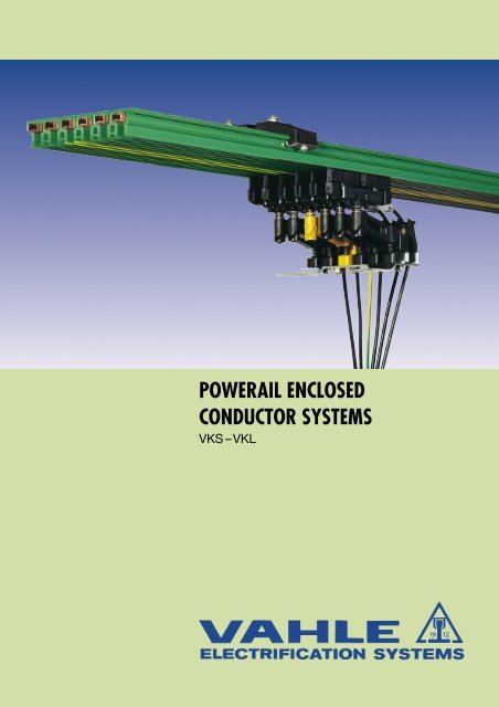
POWERAIL ENCLOSEDCONDUCTOR SYSTEMSVKS –VKL
19 12POWERAILS VKS & VKLINDEX VKS VKLBasic description 3, 4 3, 4Layout planning 5 5Engineering data, Powerail standard sections 6, 7 23Powerail curves 8 23Jointing material 8 24Hangers 9 24End caps 9 24Feeds 10, 11 24, 25Transfer guides 12 –Transfer funnels 13, 14 –Expansion sections 14 –Sectionalizing 15 24Current collectors 16, 17 25Compact collectors 16 –Accessories and spares for collectors 18 - 22 25KTW-Systems 25 25Standard brackets 26 26Snap-on brackets 26 26VKS-system, 7 pole for HRL 27 –Examples for ordering 28, 29 28Questionnaire* 30, 31 30, 31Production program 32 32Collector rings VKS (see leaflet No. 102 s) – –TECHNICAL DATAElectrical Properties:Ampacity:VoltageDielectric strengthSpecific resistanceSurface resistanceLeakage resistanceVKS VKL*** 140 A 30 A690 V 400 VDIN 53481 = 30-40 kV/mmDIN 53482 = 5 x 10 15 Ohm/cmDIN 53482 = 10 13 OhmIEC 112/VDE 0303 = CTI 600 1.1Flame test proof per DIN 4102 part 1, class B1,no flaming particles, self extinguishingConductorcopperstainlessunitssteelCross sect. 16 25 30 16 mm 2Impedance1.107 0.730 0.603 46.412Ohm/at 50 Hz1000 mResistance 1.102 0.723 0.595 46.412Ohm/1000 mMechanical properties:Flexible strength = 7360 N/mm 2 ± 10 %Tensile strength = 4910 N/mm 2 ± 10 %Resistance to chemicals of PVC housing:at + 45° C (113° F) ambient temperatureResistant to gasoline, mineral oil, grease, sodalye up to 50 % –hydro-chloric acid, concentrated – sulphuric acid up to 50 %Water absorption:max. at 100° C (212° F) = 1 %max. at 20° C ( 68° F) = 0,06 %Temperature resistance: **from – 20° C (– 4° F) up to + 55° C (131° F) up to 4 m sectionfrom 0° C (32° F) up to 40° C (100° F) more than 4 m sectionsPlease consult factory for galvanizing plants, picklinglines, other aggressive or deep freeze ambients, aswell as low voltage and data transmission applications,indicating special environmental conditions.To speed up quotations and order processing, wewould appreciate receiving your drawings or sketchesfor powerail systems with curves, dead sections,turntables, switches, etc.Please use our questionnaire, page 30 and 31.2******Please enclose the Questionnaire to your inguiry.Consult factory for use below 0° C (32° F) [deep freeze housing].80% ED
POWERAILS VKS & VKL19 12<strong>VAHLE</strong> Powerails VKS and VKL are space saving conductorsystems, designed to prevent any accidental contact and hazardto personnel and are test finger proof to regulations VDE 0470,part 1 (EN 60529), protection code IP 21.Collectors are proof against accidental touch only when fullyentered into powerail.Powerail installations within reach of hand require a special protectionon the part of operator against accidental touch of currentcollectors which are leaving the powerail (e.g. locking or cut-offthe power).This is applicable for voltages above 25 V AC respectively 60 V DC.The different plastic housings hold from 3 to 6 copper or stainlesssteel conductors. Multiple conductor systems can be easily designedby combining several plastic housings.The minimal space required allows the systems to be integratedin the crane or hoist track or in other special runway profiles.The VKS & VKL Powerail can be used for indoor and roof-over(rain protected) applications. They can be installed with lateral orsuspended mounting and straight or curved tracks are available.VKS Powerail Systemsare designed for safe mobile power feeding of:Hoists, Monorail Systems, Stacker Cranes, Machine Tools, Productionand Testing Lines, also for Sliding Switches, Turntables,Hoisting Stations, Transfers, and many other Applications, incl.Data and Signal Transmission.HousingThe well insulating plastic housing holds 3-6 conductors. 4 mstandard lengths and shorter sections to coincide with your runwayrequirements are available. The asymmetrical housingavoids phase reversing. The ground conductor is identified bythe international yellow colour coding.JointsThe plastic sections are connected with plastic joint caps, theconductors with spring-loaded copper connectors.Feed SetsEnd feeds or line feeds with terminal boxes are available, alsolow mounting line feeds for cable connection. Line feeds comefactory assembled on 1 m long Powerail sections. End feedscome unassembled without any Powerail section.HangersAll sections are to be suspended from at least 2 hangers and themaximum permissible support centres of 1 m (with doublecollectors 0.8 m) must be adhered to. The hangers are equippedwith M 6 bolts & hardware and can be mounted directly to hangerbrackets, monorail tracks or special runway profiles.The Powerail sections are snapped into the hangers. Slidinghangers allow free movement of the Powerail to compensate fortemperature variations. Fixpoint hangers with tapping screw fromanchor points (see installation procedure).Standard Support BracketsSupport brackets for easy installation are available, (see page21, 22).CollectorsThe collectors have a continuous rating of 6 A up to 120 A. Onecollector is required for each phase and earth conductor. Theground collectors have a yellow colour and different attachmentsto avoid interchangeability with phase collectors.The collectors have spring loaded carbon brushes for a constantpositive contact with the conductors.Collectors are to be mounted onto towing plates or are to beattached to the moving equipment by means of towing bracketstype UM. Systems with transfers, switches, turntables, etc. require2 single collectors or one double collector per conductor.Conductor Dead SectionsConductor dead sections can be mounted at any position of thesystem. The plastic inserts are pushed into the copper profilesand ensure a smooth transfer of the collector brushes.The length of isolating section has to consider the total length ofcarbon brush and whether carbon brush must or must not bridgethe isolating area.Special attention is required for double collectors or collectorsswitched in parallel. Use double isolating sections where necessary.Selection of conductorsin accordance to ampere load and environmental conditions:VKS …/ 60 copper conductor for power and control system and data transmission…/100 copper conductor for power and control system…/120 copper conductor for power and control system…/140 copper conductor for power and control systemSeveral combinations of cross sections are possible for one conductor type.Consider the voltage drop calculation to maintain the limits established by the motor manufacturers:Formulas:AC:DC: u = 3 x I x l x Z u = 2 l x I x Ru = Voltage drop [V] R = Resistance [Ohm/m]l = Ampere load [A] l = Power feed length [m]Z = Impedance [Ohm/m] L = System length [m]Effective length:l = L power feed located at the end of the systeml = L/2 power feed located at the mid-point of the systeml = L/4 power feed located at both ends of the systeml = L/6 power feed located at L/6 from each end of the systemThe total ampere load is determined from the nominal rated current of all motors working simultaneously on the same feedsection of your electrification system.3
19 12POWERAILS VKS & VKLVKL Powerail Systemsare designed for small current loads and serve for the powersupply of light cranes and for control current systems. The VKLPowerail can also be used for Hoists, Jib Cranes, Power Tools,Machine Tools, electrically operated Gates, Testing Lines, andother Applications.HousingThe plastic housing holds up to 5 conductors. The ground conductoris identified by international yellow colour code. 4 m standardlengths and shorter sections to coincide with your runwayrequirements are available. VKL Powerails can be used up tosystem lengths of 100 m.CouplingsThe mechanical jointing of the Powerail housing is done bymeans of a two-piece plastic joint cap. The conductors getspring-loaded copper connectors.Feed TerminalsEnd feeds and line feeds with terminal boxes are available. Theyare factory assembled on 1 m Powerail sections.HangersAll sections are to be suspended from at least 2 hangers and themaximum permissible support centres of 1 m must be adheredto. The hangers allow free movement of the powerail housing.The fix point in the centre of the run consists of a sliding hangeranchored by two locating clamps.Standard Support BracketsSupport brackets for easy installation are available (see page 25).CollectorsThe glider type collectors are guided at the PVC housing. Theyare supplied with 1 m long connecting cable. Longer cables areavailable upon request. The carbon brusheshave a continuous current capacityof 10 A (15 A at 60 % intermittent duty).Use two collectors for higher ratings. Thetowing arm is the mechanical flexibleconnection between collector and movingequipment.Conductor Dead SectionsConductor dead sections are factoryassembled at any required position of therun.4
LAYOUT PLANNING FOR VKS & VKL19 121. Scheme100/70ca. 45/26end capline feed VLS/VLEjoint materialSVN/LVsliding orfixpoint hangerstransfer guides line feed VNS/VNK end feed VEKS7VEKL = powerail section (1 m, 2 m, 3 m, 4 m or cut to suit the system)L 1 = support spacing for straight runs max. 1 mfor curved runs max. 0,5 mL 2 = extending length (max. 200 mm)L 3 = air gap for transfers, e. g. switches anddropout sections (3 - 5 mm)L 4 = space to remove feed box cover, if applicableL 5 = clearance for expansion of powerail (min. 50 mm for VKS; 150 mm for VKL).2. Symbols in layout plansTrackPowerailJoint materialJoint materialFixpoint hangerSliding hangerVKS VKL– –VKS VKLSVN –– LVVEPS VEPVAS VALine feed,powerLine feed,controlLine feed,power and controlTransfer guide, straightTransfer guide, obliqueVKS VKLVNS VNKVNS VNKVLS VLEVU –VUS –End capVESVETransfer funnelVEM –End feed,powerEnd feed,controlVEKSVEKSVEKVEKExpansion sectionIsolating assemblyDVKS –VSTS VST3. Max. Support spacingType for straightrunsfor curredrunsVKS 1000 mm 500 mmwith double collectorKDST, KDSTL KDSTLU800 mm 400 mmKST(L), KSTU 30, 55 picture 1AVKL 1000 mm 500 mmpicture 1A < 300 mm Support spacing 0,8 mA > 300 mm Support spacing 1,0 m5
19 12ENGINEERING DATA VKSStraight sectionsStandard length 4 and 6 m.*****HS = w/ PESS = w/o PE*** 6Attention: Joint material to be ordered separately (see page 8).LHRHNumber Continuous Voltage Voltage drop Minimum Conductor Cross Section****Type of Ampere Rating per 100 m Clearence mm 2con- Rating at full ratingductors A V V mm L1 - L3 PE 1, 2, N, Lat 35° CVKS 3/ 60 HS 3 60 690 11.5 7 – 1x16 2x16VKS 3/ 60 SS 3 60 690 11.5 7 – 1x16 2x16VKS 3/100 HS 3 100 690 12.6 7 – 1x25 2x25VKS 3/100 SS 3 100 690 12.6 7 – 1x25 2x25VKS 3/120 HS 3 120 690 12.5 7 – 1x30 2x30VKS 3/120 SS 3 120 690 12.5 7 – 1x30 2x30VKS 3/140 HS 3 140** 690 11.3 7 – 1x35 2x35VKS 3/140 SS 3 140** 690 11.3 7 – 1x35 2x35Straight sectionsStandard length 4 und 6 m.******** 6Attention: Joint material to be ordered separately (see page 8).LHRHNumber Continuous Voltage Voltage drop Minimum Conductor Cross Section****Type of Ampere Rating per 100 m Clearence mm 2con- Rating at full ratingductors A V V mm L1 - L3 PE 1, 2, N, Lat 35° CVKS 4/ 60 HS 4 60 690 11.5 7 3x16 1x16 –VKS 4/ 60 SS 4 60 690 11.5 7 3x16 1x16 –VKS 4/100 HS 4 100 690 12.6 7 3x25 1x16 –VKS 4/100 SS 4 100 690 12.6 7 3x25 1x16 –VKS 4/120 HS 4 120 690 12.5 7 3x30 1x16 –VKS 4/120 SS 4 120 690 12.5 7 3x30 1x16 –VKS 4/140 HS 4 140** 690 11.3 7 3x35 1x16 –VKS 4/140 SS 4 140** 690 11.3 7 3x35 1x16 –Straight sectionsStandard length 4 und 6 m.******** 6Attention: Joint material to be ordered separately (see page 8).LHRHNumber Continuous Voltage Voltage drop Minimum Conductor Cross Section****Type of Ampere Rating per 100 m Clearence mm 2con- Rating at full ratingductors A V V mm L1 - L3 PE 1, 2, N, Lat 35° CVKS 5/ 60 HS* 5 60 690 11.5 7 3x16 1x16 1x16VKS 5/ 60 SS* 5 60 690 11.5 7 3x16 1x16 1x16VKS 5/100 HS* 5 100 690 12.6 7 3x25 1x16 1x16VKS 5/100 SS* 5 100 690 12.6 7 3x25 1x16 1x16VKS 5/120 HS* 5 120 690 12.5 7 3x30 1x16 1x16VKS 5/120 SS* 5 120 690 12.5 7 3x30 1x16 1x16VKS 5/140 HS* 5 140** 690 11.3 7 3x35 1x16 1x16VKS 5/140 SS* 5 140** 690 11.3 7 3x35 1x16 1x16VKS 6/ 60 HS 6 60 690 11.5 7 3x16 1x16 2x16VKS 6/ 60 SS 6 60 690 11.5 7 3x16 1x16 2x16VKS 6/100 HS 6 100 690 12.6 7 3x25 1x16 2x16VKS 6/100 SS 6 100 690 12.6 7 3x25 1x16 2x16VKS 6/120 HS 6 120 690 12.5 7 3x30 1x16 2x16VKS 6/120 SS 6 120 690 12.5 7 3x30 1x16 2x16VKS 6/140 HS 6 140** 690 11.3 7 3x35 1x16 2x16VKS 6/140 SS 6 140** 690 11.3 7 3x35 1x16 2x166**********VKS 5 eliminates conductor number 6; plastic housing however identical to VKS 6.80 % EDSection is superseded at 20° C UT.Same cross section at PE (ground) when used for control line. Other conductor combinations are possible.
STRAIGHT SECTIONS VKS19 12➊Conductor Weight Cat.-No.Materialkg/mCu 1.221 153 89•Cu 1.221 153 94•Cu 1.454 153 90•Cu 1.454 153 95•Cu 1.589 153 91•Cu 1.589 153 96•Cu 1.724 154 96•Cu 1.724 156 08•Installation: lateral➊Installation: horizontal➊Conductor Weight Cat.-No.Materialkg/mInstallation: lateralCu 1.459 153 99•Cu 1.459 154 04•Cu 1.693 154 00•Cu 1.693 154 05•Cu 1.828 154 01•Cu 1.828 154 06•Cu 1.956 154 31•Cu 1.956 156 54•➊Installation: horizontalConductor Weight Cat.-No.Materialkg/mCu 2.058 154 09•Cu 2.058 154 14•Cu 2.292 154 10•Cu 2.292 154 15•Cu 2.427 154 11•Cu 2.427 154 16•Cu 2.549 154 87•Cu 2.549 156 55•Cu 2.202 154 19•Cu 2.202 154 24•Cu 2.436 154 20•Cu 2.436 154 25•Cu 2.571 154 21•Cu 2.571 154 26•Cu 2.693 152 60•Cu 2.693 156 56•12611650 34M 6245max. 1015 21,518 18 18 18 18Installation: lateral21PEL3L2L17M 6max. 1018 18 18 18 18L1 L2 L3 PE 1 21 2 3 4 5 6Installation: horizontal➊ Marking refers to control lines.➊12,5654321➊1521,5*****For supply lengths above 4 m refer to restricted ambient temperature (page 2).7• For full type designation add length suffix of Powerail Section, e. g. VKS 4/120-2 HS for Cat.-No. 154 012. Other sections to coincide withyour runway requirements are made up from the next larger straight length.
19 12COMPONENTS VKSCurved sections*per your layout drawingmax. L = 3.6 m, support spacing ~ 500 mm, max. angle 180°RJoint MaterialHorizontal curve, R. H. = web outsideHorizontal curve, L. H. = web inside (not shown)Inside curve: RwebOutside curve: R100web15Inside curve, lateral = conductor insideOutside curve, lateral = conductor outside (not shown)surcharge cat. nos. forRCat.-No.mm VKS 3Horizontal curve, R. H. 400 – 900 150 385Horizontal curve, L. H. 400 – 900 150 386Horizontal curve, R. H. > 900 153 120Horizontal curve, L. H. > 900 153 130Inside curve, lateral 200 – 800 150 387Inside curve, lateral > 800 153 040Outside curve, lateral 200 – 800 150 388Outside curve, lateral > 800 153 050Type Poles Weight kg Cat.-No.SVN 3/ 10 - 100 3 0.112 156 533SVN 3/120 - 140 3 0.112 156 534Curved sections*per your layout drawingmax. L = 3.6 m, support spacing ~ 500 mm, max. angle 180°Configuration as shown aboveJoint Material10015surcharge cat. nos. forRmmCat.-No.VKS 4Horizontal curve, R. H. 400 – 900 150 389Horizontal curve, L. H. 400 – 900 150 391Horizontal curve, R. H. > 900 153 717Horizontal curve, L. H. > 900 150 110Inside curve, lateral 200 – 800 150 392Inside curve, lateral > 800 153 718Outside curve, lateral 200 – 800 150 393Outside curve, lateral > 800 150 100Type Poles Weight kg Cat.-No.SVN 4/ 10 - 100 4 0.136 156 535SVN 4/120 - 140 4 0.136 156 536Curved sections*per your layout drawingmax. L = 3.6 m, support spacing ~ 500 mm, max. angle 180°Configuration as shown aboveJoint Material10015surcharge cat. nos. forRmmCat.-No.VKS 5Cat.-No.VKS 6Horizontal curve, R. H. 400 – 900 150 394 150 398Horizontal curve, L. H. 400 – 900 150 395 150 399Horizontal curve, R. H. > 900 153 719 153 721Horizontal curve, L. H. > 900 152 090 152 110Inside curve, lateral 200 – 800 150 396 150 401Inside curve, lateral > 800 153 720 153 722Outside curve, lateral 200 – 800 150 397 150 402Outside curve, lateral > 800 152 080 152 100Horizontal curve radius < 1500 mm up to 45 degreesHorizontal curve radius > 1500 mm up to 90 degreesType Poles Weight kg Cat.-No.SVN 5/ 10 - 100 5 0.180 156 537SVN 5/120 - 140 5 0.180 156 538SVN 6/ 10 - 100 6 0.194 156 539SVN 6/120 - 140 6 0.194 156 5408* Curved sections will be factory prepared with a 100 mm straight section on both ends. Horizontal curves with more than 90 degreesshould be divided in two or more sections.
COMPENENTS VKS19 12Fixpoint hanger*with tapping screw & clampSliding hanger*End cap**suitable L. H. and R. H.M 6M 615 2015204813length of powerail30tappingscrew & clamp30Type Weight kg Cat.-No.VEPS 3 0.042 153 070Type Weight kg Cat.-No.VAS 3 0.036 153 060Type Weight kg Cat.-No.VES 3 - L 0.033 153 080VES 3 - M 0.033 152 023Fixpoint hanger*with tapping screw & clampSliding hanger*End cap**suitable L. H. and R. H.15 20M 61520M 64813length of powerail30tappingscrew & clamp30Type Weight kg Cat.-No.VEPS 4 0.046 150 120Type. Weight kg Cat.-NoVAS 4 0.040 150 130Type Weight kg Cat.-No.VES 4 - L 0.039 150 140VES 4 - M 0.039 152 022Fixpoint hanger*with tapping screw & clampSliding hanger*End cap**suitable L. H. and R. H.50M 650M 6152015204813length of powerail30tappingscrew & clamp30Type Weight kg Cat.-No. Type Weight kg Cat.-No.VEPS 6 0.062 152 120VAS 6 0.056 152 130* Complete with hardware (bolts, nuts, spring washers). Support spacing see page 5.** L = loose; c/w hardwareM = Factory assembledType. Weight kg Cat.-NoVES 6 - L 0.051 152 140VES 6 - M 0.051 152 0219
19 12COMPONENTS VKSEnd feed*Terminal box with terminal clamps10015013Section190Type Cable Gland A Weight kg Cat.-No.VEKS 3/10 - 120 L ST-M 40 x 1.5 10 - 120 1.150 156 422Surcharge for assemblage 156 423End feed*Terminal box with terminal clamps10015013Section190Type Cable Gland A Weight kg Cat.-No.VEKS 4/10 - 120 L ST-M 40 x 1.5 10 - 120 1.230 156 421Surcharge for assemblage 156 423End feed*Terminal box with terminal clamps10015013Section190Type Cable Gland A Weight kg Cat.-No.VEKS 5/10 - 120 LST-M 40 x 1.5ST-M 20 x 1.510 - 120 1.380 156 420VEKS 6/10 - 120 LST-M 40 x 1.5ST-M 20 x 1.510 - 120 1.460 156 419Surcharge for assemblage 156 42310* End feeds loose as components. Sections are to be ordered separately (see page 7).
COMPONENTS VKS19 12Line Feed*Terminal box with terminal clamps190(340)150100500 500Dimensions in parenthesis for VNS 3/100-140Line Feed*without cable connection; cable by others terminal bolt M 6.through holeØ 11 mm15015500 500Type**Weight Cat.-No. Cat.-No.CableA kg (w/ PE) (w/o PE)GlandsHS SS****VNS 3/ 60 60 2.000 150 247 150 252VNS 3/100 ST-M 40 x 1,5 100 3.176 150 248 150 543VNS 3/120 120 3.317 150 249 150 544VNS 3/140 ST-M 63 x 1,5 140 3.812 156 774 156 775Weight Cat.-No. Cat.-No.Type** A kg (w/ PE) (w/o PE)HSSSVLS 3/ 60 60 1.286 150 218 150 222VLS 3/100*** 100 1.622 150 219 150 536VLS 3/120*** 120 1.726 152 341 152 343VLS 3/140*** 140 1.861 156 550 156 776Line Feed*Terminal box with terminal clampsLine Feed*without cable connection; cable by others terminal bolt M 6.190(340)150100500 500Dimensions in parenthesis for VNS 4/100-140through holeØ 11 mm15015500 500Weight Cat.-No. Cat.-No.CableType**A kg (w/ PE) (w/o PE)GlandsHS SS****VNS 4/ 60 60 2.450 150 255 150 261VNS 4/100 ST-M 40 x 1,5 100 3.512 150 256 150 545VNS 4/120 120 3.700 150 257 150 546VNS 4/140 ST-M 63 x 1,5 140 4.315 152 311 156 547Weight Cat.-No. Cat.-No.Type** A kg (w/ PE) (w/o PE)HSSSVLS 4/ 60 60 1.542 150 225 150 229VLS 4/100*** 100 1.882 150 226 150 517VLS 4/120*** 120 1.987 152 336 152 338VLS 4/140*** 140 2.122 156 437 156 777Line Feed*Terminal box with terminal clampsLine Feed*without cable connection; cable by others terminal bolt M 6.190(340)150100through holeØ 11 mm15015500 500Dimensions in parenthesis for VNS 5/100-140 and 6/100-140500 500Type**Weight Cat.-No. Cat.-No.CableA kg (w/ PE) (w/o PE)GlandsHS SS****VNS 5/ 60 1 x ST-M 40 x 1,560 3.316 150 264 150 269VNS 5/100 1 x ST-M 20 x 1,5100 4.265 150 265 150 547VNS 5/120 120 4.500 150 266 150 548VNS 5/140 1x 1x ST-M ST-M 20 63 x x 1,5 1,5 140 5.235 152 628 156 548VNS 6/ 60 60 3.662 150 273 150 2781 x ST-M 40 x 1,5VNS 6/100 100 4.498 150 274 150 5491 x ST-M 20 x 1,5VNS 6/120 120 4.780 150 275 150 550VNS 6/140 1x 1x ST-M ST-M 20 63 x x 1,5 1,5 140 5.634 152 626 156 549Weight Cat.-No. Cat.-No.Type** A kg (w/ PE) (w/o PE)HSSSVLS 5/ 60 60 2.165 150 233 150 237VLS 5/100*** 100 2.505 150 234 150 539VLS 5/120*** 120 2.609 152 328 152 330VLS 5/140*** 140 2.744 156 557 156 558VLS 6/ 60 60 2.317 150 240 150 244VLS 6/100*** 100 2.657 150 241 150 541VLS 6/120*** 120 2.762 152 332 152 334VLS 6/140*** 140 2.897 156 559 156 560*** Suffix types e. g. VNS 3/60 w/ PE VNS 3/60 HS Cat.-No. 150 247.*** Cable connection w/ special cable lug (enclosed) for 35 mm 2 single core cable (max. 8,5 mm Ø) for 140 A,25 mm 2 (max. 8,2 mm Ø) for 120 A, 16 mm 2 (max. 6,5 mm Ø) for 100 A.**** Cable gland ST-M 63 x 1,5 for D = 34 to 45, ST-M 40 x 1,5 for D = 19 to 28, ST-M 20 x 1,5 for D = 7 to 13Feed sets come ready assembled on 1 m Powerail sections and are part of the system length. Cable by others.11
19 12TRANSFER GUIDES VKSTransfer guide*for transfers, switches, spur linesmax. horizontal and vertical offset ± 2 mmApplication: straight cutsoblique cuts, lateralTransfer guide oblique cut*for switches and turntables prepared per your layout drawings.Application: oblique cuts, horizontal25**web30**webPowerailxIP 21 up to x = 45°Photo shows L. H. versionTypeCat.-No.L. H. versionCat.-No.R. H. versionVU 3 S-M 150 191 150 192VU 3 S-L 150 188M = factory assembled L = loose; c/w hardwareTransfer guide*for transfers, switches, spur linesmax. horizontal and vertical offset ± 2 mmApplication: straight cuts30**webPhoto shows L. H. versionTypeCat.-No.L. H. versionCat.-No.R. H. versionVUS 3 H 150 410 150 420Transfer guide oblique cut*for switches and turntables prepared per your layout drawings.Application: oblique cuts, horizontal and lateral30**webxIP 21 up to x = 45°Photo shows L. H. versionType VUS 4 HPhoto shows L. H. versionType VUS 4 STypeCat.-No.L. H. versionCat.-No.R. H. versionVU 4 150 160 150 390TypeCat.-No.L. H. versionCat.-No.R. H. versionVUS 4 H 150 170 150 400VUS 4 S 153 564 153 565H = for horizontal mounting S = for lateral mountingTransfer guide*for transfers, switches, spur linesmax. horizontal and vertical offset ± 2 mmApplication: straight cutsoblique cuts, lateral20**web2 x M 6 inserts,8 mm deepc/c 50 mmTransfer guide oblique cut*for switches and turntables prepared per your layout drawings.Application: oblique cuts, horizontalType VUS 6 H30**webPhoto shows L. H. version(also fits for VKS 5 & VKS 6 powerail)Cat.-No.Cat.-No.TypeL. H. version R. H. versionVU 6 S-M 153 801 153 802VU 6 S-L 150 215PowerailPhoto shows L. H. versionxIP 21 up to x = 45°TypeCat.-No.Cat.-No.L. H. version R. H. versionVUS 5 H 152 170 152 300VUS 6 H 152 310 152 320M = factory assembled L = loose; c/w hardware ***12*********Photos show transfer guides being integrated in or attached to a powerail section. These sections are to be ordered as a part of the system.Other entry/exit chutes are available. Consult factory.w/o conductorsPreparation of Powerail ends by others, following attached instructions.
TRANSFER FUNNELS VKS19 12Transfer funnels for KSTU 30/55for max. Speed v = 100 m/Min.**6811818CA18BD1818248282,5209,4°Powerail with transfer guide VU is to be ordered seperately35max. 800slotted Langloch hole 7x153756440Type A mm B mm C mm D mm Weight kg Cat.-No. VU…L* VU…R*Transfer funnels for KSTLU / KDSTLUfor max. Speed v = 100 m/Min.**579max. 800Powerail with transfer guide VU is to be ordered seperately35slotted Langloch hole 7x152506440Type A mm B mm C mm D mm Weight kg Cat.-No. VU…L* VU…R*** Powerail section must be factory prepared.Order separately for left hand VU…L, for right hand VU…R.EFT V3 - KSTU 62 148 175 198 3.140 156 144 150 370 150 380EFT V4 - KSTU 80 166 193 216 3.320 156 145 150 160 150 390EFT V6 - KSTU 116 202 229 252 3.680 156 146 152 280 152 290104,5CA10,5°1818181818EFT V3 - KDSTLU 54 140 166 190 3.060 152 585 150 370 150 380EFT V4 - KDSTLU 72 158 184 208 3.260 152 586 150 160 150 390EFT V6 - KDSTLU 108 194 220 244 3.650 152 587 152 280 152 29012,582,524BD13
19 12TRANSFER FUNNELS VKSEXPANSION SECTIONS VKSTransfer funnels for KSFU 25*for max. speed v = 100 m/Min.**335851060,515°24Powerail with transfer guide VU is to be ordered seperately35max. 8001818CA18BD18184slotted Langloch hole 7x15154,56430Type A mm B mm C mm D mm Weight kg Cat.-No. VU…L* VU…R*EFT V3 - KSFU 25 62 120 108 162 1.400 153 337 150 370 150 380EFT V4 - KSFU 25 80 138 126 180 1.520 153 336 150 160 150 390EFT V6 - KSFU 25 116 174 162 216 1.760 153 335 152 280 152 290Expansion sections1000 (±25)„A“(0 - 50 mm)Type***Weight Cat.-No. Bestell-Nr.kg (w/ PE) (w/o PE)HSSSDVKS 3/ 60 1.900 153 230 153 240DVKS 3/100 2.090 153 250 150 551DVKS 3/120 2.215 153 623 150 552DVKS 3/140 2.346 156 588 156 589DVKS 4/ 60 2.412 150 480 150 510DVKS 4/100 2.662 150 490 150 516DVKS 4/120 2.852 153 628 150 553DVKS 4/140 3.027 156 590 156 595Weight Cat.-No. Bestell-Nr.Type*** kg (w/ PE) (w/o PE)HSSSDVKS 5/ 60 3.266 152 340 152 380DVKS 5/100 3.586 152 350 150 554DVKS 5/120 3.811 153 633 150 555DVKS 5/140 4.030 156 596 156 597DVKS 6/ 60 3.582 152 360 152 390DVKS 6/100 3.962 152 370 150 556DVKS 6/120 4.242 153 638 150 557DVKS 6/140 4.504 156 598 156 599ApplicationExpansion sections are required to compensate for expansionand contraction in system expansion gaps (building or track).The expansion capacity is 50 mm. More tolerance requiremore than one VKS expansion section.They do not interrupt electrical power, so there is no need foran extra feeding. Expansion joints do not influence the voltagedrop of a system.MountingThe expansion section is installed in the center between twofix points in the building/track expansion gap area.The gap dimension “A” equals the gap of the building/track.See adjacent Fig. 1.Fig. 1Expansion gapFixpoint hangerExpansion section14* Powerail section must be factory prepared.Order separately for left hand VU…L, or for right hand VU…R.Higher speeds on request.Suffix types e. g. DVKS 3/10 with PE DVKS 3/60 HS Cat.-No. 153 230.*****
SECTIONALIZING VKSCURRENT COLLECTOR VKS19 12Conductor dead section for control signalsplease indicate where and which conductors are to be interrupted.Type Cat.-No. ColourVSTS 1/10-100 M 150 150 blackVSTS 1/10-100 L 150 419 blackVSTS 1/120 M 151 674 whiteVSTS 1/120 L 151 669 whiteVSTS 1/140 M 155 335 whiteVSTS 1/140 L 156 336 whiteM = factory assembled; L = loose30 dead sectionCurrent collectors Dimensions in parenthesis for KSTLwith 2 m connecting cable; contact pressure: ~ 5 NCurrent collectorSwivel & lift ± 10 mm · Contact pressure: 3 N13,5 (17,8 KSTU)85604,44835114,5140 (190)85 (95)1260plugterminal6.3 x 0.8for FLA 2.5or WFLA 2.5ca. 70ZF 1M 5, PhaseM 6, GroundTyp e***KST 30KST 55KSTL 30KSTL 55KSTU 30****KSTU 55****AmpacityA305530553055Connecting cableA/ d max/mm 2 mm2.506.002.506.002.506.00511511511lift & swivelmm±20±20±30±30±20±20Weightkg0.2400.3680.2400.3680.2400.368phase -PH152 085154 438152 089154 443152 087154 441Cat.-No.For double arrangement of current collectors and supportspacing for Powerail see page 5.groundPE152 086154 439152 091154 444152 088154 442Type***Ampacity Weight Cat.-No.A kg Phase PH Ground PEKST 20 20 0.050 155 071 155 072Selection of connecting cable see page 18.Current collector6650114,2Double current collector3510285ca. 14113,870plugterminal6.3 x 0.8for FLA 2.5or WFLA 2.5ca. 70ZF 1M 5, PhaseM 6, Ground80plugterminal6.3 x 0.8for FLA 2.5orWFLA 2.5ca. 70plugterminal6.3 x 0.8for WFLA 2.5ZF 2M 5, PhaseM 6, GroundSwivel & lift: ± 10 mm · Contact pressure: 3.5 NSwivel & lift: ± 10 mm · Contact pressure 3.5 N per brushAmpacity Weight Cat.-No.WeightCat.-No.Type *** A kg Phase PH Ground PEType ***kg Phase PH Ground PEKST 25 25 0.060 155 013 155 014 KST 2/40 0.080 168 137 168 138Ampacity: 1 flat plug 25 A, 2 flat plugs 2 x 20 ASelection of connecting cable see page 18.Selection of connecting cable see page 18.**********Marking of conductors see page 6.Length of conductor w/o power (other lengths on request).Suffix types e. g. KST 20 KST 20 PH Cat.-No. 155 071, KST 30 w/ PE KST 30 HS Cat.-No. 152 085Collector for transfer funnel EFT V…– KSTU. In the area of the funnel ± 15 mm in every direction.15
19 12CURRENT COLLECTORS FOR VKSCompact current collectorAmpacity: 1 plug terminal 32 A – FLA 2,540 A – FLA 4,018max. 1276 5 432155 A – FLA 6,0For conductor spacing of 18 mmSwivel & lift: ± 15 mmContact pressure: 3.5 N per brushGround position per request (see page 5)for safety reasons duringmaintenance ground collectoris always first and last contact88abplugterminal6.3 x 0.8for FLA53***1574271RF 315max. 18DF 2No.Cat.-No.Type* of a** b**Weight for power incl. for controlPoles mm mm kg 1 ground HS STKESR 32-55-2 2 54 79 0,192 – 155 209KESR 32-55-3 3 54 79 0,310 155 203 155 210KESR 32-55-4 4 54 79 0,372 155 204 155 211KESR 32-55-5 5 80 115 0,485 155 205 155 212KESR 32-55-6 6 80 115 0,547 155 206 155 213Separately available: PH PEKESR 32-55 collector 168 304 168 305Selection of connecting cable see page 18Compact current collectorAmpacity: 1 plug terminal 25 Amax. 138Compact current collectorwith 1 m connecting cablefor transfer funnelEFT V…– KSFU 25max. 1381888abplugterminal6.3 x 0.8for WFLA 2.553***156543721427114RF 3max. 18DF 2For conductor spacingof 18 mmSwivel & lift: ± 15 mmContact pressure: 3.5 Nper brushGround position per request(see page 5)for safety reasons duringmaintenance ground collectoris always first and last contact18plugterminal6.3 x 0.8for FLA 2,5Dimensions of base plate see KSF 25654321RF 3max. 18DF 2Type*Cat.-No.No. ofPolesa**mmb**mmWeight for power incl.for conrolkg 1 ground HS STKSF 25-2 2 18 43 0.168 – 155 038KSF 25-3 3 54 79 0.274 155 028 155 039KSF 25-4 4 54 79 0.324 155 029 155 040KSF 25-5 5 80 115 0.425 155 030 155 041KSF 25-6 6 80 115 0.475 155 031 155 042Separately available: Phase PH Ground PEKSF 25 collector 0,050 155 023 155 024Selection of connecting cable see page 17.Type*Cat.-No.No. ofPolesa**mmb**mmWeight for power incl.for controlkg 1 ground HS STKSFU 25-2 2 18 43 0.182 155 050 155 059KSFU 25-3 3 54 79 0.295 155 051 155 060KSFU 25-4 4 54 79 0.352 155 052 155 061KSFU 25-5 5 80 115 0.460 155 053 155 062KSFU 25-6 6 80 115 0.517 155 054 155 063Separately available: Phase PH Ground PEKSFU 25 collector 155 025 155 026Compact double current collector6541Ampacity: 1 flat plug 25 A, 2 flat plugs 2 x 20 Amax. 145plug1832terminal6.3 x 0.8for WFLA 2.598bDF 3a53**1574271plugterminal6.3 x 0.8quick connect plugandflexible cable WFLA2.5 sqmm, L = 0.5 mincl.15max. 12DF 1For conductor spacing of 18 mmSwivel & lift: ± 15 mmContact pressure: 3.5 N per brushGround position per request (see page 5)for safety reasons duringmaintenance ground collectoris always first and last contactType*Cat.-No.No. of a** b **Weight for power incl. for controlPoles mm mm kg HS STKDS 2/40-2-18 2 54 79 0.264 155 078 155 090KDS 2/40-3-18 3 54 79 0.334 155 079 155 091KDS 2/40-4-18 4 54 79 0.404 155 080 155 092KDS 2/40-5-18 5 80 115 0.525 155 081 155 093KDS 2/40-6-18 6 80 115 0.595 155 082 155 094Separately available: Phase PH Ground PEKDS 2/40 collector 0,070 168 073 168 07416***Suffix types e. g. KSF 25-3 w/ PE KSF 25-3 HS Cat.-No. 155 028.Base plate of KSF and KSFU 25 2-, 4- or 6-poles always. At KDS 2/40 and KESR 32-55 4- or 6-poles always.Current collector 3 poles base plate 4 poles, 4 th pole is free.Current collector 5 poles base plate 6 poles, 6 th pole is free.***for 5- and 6-poles execution only.
Current collector1001007512PEc/w 2 m cableswivel & lift: ± 20 mm; contact pressure: 9 NAmpacityø max. Weight PhaseConnecting cableCat.-No.Type**A mm 2 mm kgPHKST 15 15 2.5 4.4 0.256 150 891KST 40 40 6.0 11.0 0.428 152 840KST 60 60 10.0 12.5 0.588 153 675Current collector1501007512PEc/w 2 m cableswivel & lift: ± 40 mm; contact pressure: 9 NAmpacityø max. Weight PhaseConnecting cableCat.-No.Type**A mm 2 mm kgPHKSTL 15 15 2.5 4.4 0.272 150 893KSTL 40 40 6.0 11.0 0.453 152 860KSTL 60 60 10.0 12.5 0.591 153 677Current collector for transfer funnel*EFT V…-KSTLU1501007512c/w 2 m cablePEswivel: ± 40 mm; lift: ± 20 mm; (in funnel area ± 15 mm)contact pressure: 9 NAmpacityø max. Weight PhaseConnecting cableCat.-No.Type**A mm 2 mm kgPHKSTLU 15 15 2.5 4.4 0.313 150 895KSTLU 40 40 6.0 11.0 0.499 153 791KSTLU 60 60 10.0 12.5 0.652 153 793* Collector maintains center phase position for easy retracking.** Suffix types e. g. KST 15 KST 15 PH Cat.-No. 150 891. CURRENT COLLECTORS FOR VKSDouble current collector1742001007512c/w 2 x 2 m cableswivel & lift: ± 20 mm; contact pressure: 9 N per brushAmpacityø max. Weight PhaseConnecting cableground Type**PEA mm 2 mm kgPH150 892 KDST 30 30 2.5 4.4 0.471 150 897152 850 KDST 80 80 6.0 11.0 0.821 152 960153 676 KDST 120 120 10.0 12.5 1.114 153 67917 Double current collector43001501007512c/w 2 x 2 m cableswivel & lift: ± 40 mm; contact pressure: 9 N per brushAmpacityø max. Weight PhaseConnecting cableground Type**PEA mm 2 mm kgPH150 894 KDSTL 30 30 2.5 4.4 0.492 150 899152 870 KDSTL 80 80 6.0 11.0 0.822 152 980153 678 KDSTL 120 120 10.0 12.5 1.188 153 681Double current collector for transfer funnel*17EFT V…-KSTLU43001001507512c/w 2 x 2 m cableswivel: ± 40 mm; lift: ± 20 mm; (in funnel area ± 15contact pressure: 9 N per brushAmpacityø max. Weight PhaseConnecting cableground Type**PEA mm 2 mm kgPH150 896 KDSTLU 30 30 2.5 4.4 0.541 150 902153 792 KDSTLU 80 80 6.0 11.0 0.895 153 786153 794 KDSTLU 120 120 10.0 12.5 1.231 153 79519groundPE150152153groundPE150152153groundPE15015315312898970680901990682903787796Cat.-No.Cat.-No.mm)Cat.-No.approx. 135max. released hight6518851885approx. 501212126518851885approx. 5017ca. 135max. released hight
19 12COLLECTOR COMPONENTS FOR VKSConnecting cable high-flexible for current collector(Allocation to current collectors on pages 15 and 16)FHWFHCross section Ø Weight Cat.-No.Type mm 2 mm kg phase groundblack green/yellowFLA 2.5 2.5 4.0 0.080 165 049 165 050FLA 4 4.0 6.0 0.100 165 051 165 052FLA 6 6.0 7.0 0.015 166 368 166 369WFLA 2.5 2.5 4.0 0.080 168 107 168 108FLA1 m long with flat plug 6.3 x 0.8 m;longer cable availableWFLAFlat plug onlyType for Cross section Cat.-No.mm 2FH 2.5 2.5 165 120FH 4-6 4.0 165 121WFH 2.5 2.5 168 109Collector bracketsfor current collectorKST/KDST see page 17for current collectorKST 30-55 see page 15for control-collectorKST/KDST page 17, KST 30-55 page 15w/ PE w/o PE1840 mm wideslotted hole30 x 111290 30170for groundcollector62 18 62 440 mm wideslotted hole11 x 3012309017040 mm wideslotted hole11 x 30123030309017015651565Type Weight kg Cat.-No.Type Weight kg Cat.-No.Type Weight kg Cat.-No.UMAS 12 HS -A0.600152 233UMAS 12 HS-B0.600152 232UMAS 12 ST0.600152 234Collector bracket for current collectorsfor KST 15 to KDSTLU 120Cable attachment clamp for current collectorsfor KST 15 to KDSTLU 1204630156560054 1812prepared for ground collectorLonger brackets furnished on special order.In this case you should provide an extra support to avoidbending or twisting of the collector bracket.Type Length mm Weight kg Cat.-No.UMV 12 600 0.710 153 775Type Weight kg Cat.-No.KBK 0.030 153 51918
COLLECTOR COMPONENTS FOR VKS19 12Copper-graphite brush assembly7560756048352319RHRH10RHKMK 2066501028535RH1010285GF 135GF 1100751007523RHRHRH101010RH23101010PE identificationKMK 30-55 PHKMK 30-55 PE66507660RHRH23231010KMK 25 KMKUMK 4025/18*KMK 2/40DSW 2/40 DS 2/40 KMK 60 KMK 60 Udim. RH = allowed rest of hightType for collectors Thickness of brush RH mm Weight kg Cat.-No.KMK 30-55 PH KST 30 – KSTL 55, KSTU 30 - 55 4.4 mm 4.0 0.031 154 440KMK 30-55 PE KST 30 – KSTL 55, KSTU 30 - 55 4.4 mm 4.0 0.034 154 453KMK 20 KST 20 4.5 mm 6.0 0.020 155 068KMK 25 KST 25, KSF 25 4.2 mm 3.5 0.030 155 000KMKU 25/18 KSFU 25 4.2 mm 3.5 0.035 155 002MK 55 KESR 32-55 4.2 mm 3.5 0.042 168 225KMK 2/40 KST 2/40 3.8 mm 5.0 0.050 168 135DSW 2/40 KDS 2/40 3.8 mm 5.0 0.050 168 151DS 2/40 KDS 2/40 3.8 mm 5.0 0.050 168 065KMK 60 KST 15 – KDSTL 120 4.0 mm 5.0 0.110 153 512KMK 60 U KSTLU 15 – KDSTLU 120 4.0 mm 5.0 0.120 153 513* 18 mm wide.19
19 12COMPONENTS FOR VKSSpringsSSDDLPressure spring DFGuiding spring GFLTension spring ZF/RFTypefor collectorsS D Lmm mm mmCat.-No.ZF 1 KST 20, KST 25 0.63 5.40 22.00 153 514ZF 2 KST 2/40 0.85 6.45 24.00 153 515ZF 3 KST 15 thru KDST 120 1.10 10.80 28.50 153 516ZF 4 KSTL 15 thru KDSTL 120 and KSTLU 15 thru KDSTLU 120 1.30 11.00 29.00 153 517DF 1 KDS 2/40 1.00 7.00 38.00 153 847DF 2 KSF 25, KESR 32-55 0.90 7.70 43.00 153 848DF 3 KDS 2/40 0.55 9.00 23.90 152 011RF 3 KSF 25, KESR 32-55 0.40 4.40 31.00 153 849GF 1 KDS 2/40 0.35 2.00 22.00 153 850Spare partsTypeCat.-No.Joint cap for VKS 3 152 012Joint cap for VKS 4 152 013Joint cap for VKS 5 and 6 152 014Plug-in connector (1pole, copper) for VKS…/10 - 100 A 153 803Plug-in connector (1 pole, copper, tin plated) for VKS…/120 - 140 A 152 672Insulating piece for sectionalizing (1 pole) for VSTS 1/10 - 100 L 150 419Insulating piece for sectionalizing (1 pole) for VSTS 1/120 L 151 669Insulating piece for sectionalizing (1 pole) for VSTS 1/140 L 156 336Feed terminal, (1 pole) for line feed VNS 151 774Feed terminal, (1 pole) for line feed VLS 153 60320
COLLECTOR COMPONENTS FOR VKS19 12Current collector series KST 15 thru KDSTLU 120Part-No. Description Weight kg Cat.-No.1 Brush (see page 19) – –2 Collector base for KST 15 thru KST 60 Phase PH153 7360.0803 Ground PE 153 7372 Collector base for KDST 30 thru KDST 120 Phase PH153 7380.1003 Ground PE 153 7392 Collector base for KSTL 15 thru KSTL 60 Phase PH153 7400.0903 Ground PE 153 7412 Collector base for KSTLU 15 thru KSTLU 60 Phase PH153 8040.0903 Ground PE 153 8052 Collector base for KDSTL 30 thru KDSTL 120 Phase PH153 7420.1303 Ground PE 153 7432 Collector base for KDSTLU 30 thru KDSTLU 120 Phase PH153 8060.1303 Ground PE 153 8074 Spring (see page 20) – –5 Connecting cable AEA 2,5 PH, 2 m long Phase PH151 3740.072Connecting cable AEA 2,5 PE, 2 m long Ground PE 151 3755 Connecting cable AEA 6 PH, 2 m long Phase PH153 7440.260Connecting cable AEA 6 PE, 2 m long Ground PE 153 7455 Connecting cable AEA 10 PH, 2 m long Phase PH153 7460.400Connecting cable AEA 10 PE, 2 m long Ground PE 153 7476 Rubber spring* for KSTLU 15, KSTLU 40, KSTLU 60, KDSTLU 30, 0.008 153 748KDSTLU 80, KDSTLU 120* When ordering brush the rubber spring as shown will be included.21
19 12COLLECTOR COMPONENTS FOR VKSCurrent collectors KST 30-55 thru KSTL 30-55, KSTU 30-55Part-No. Description Weight kg Cat.-No.1 Brush Phase PH 0.031 154 4402 Brush Ground PE 0.031 154 4533 Collector base & arm KST, complete Phase PH 0.083 152 2753 Collector base & arm KSTL, complete Phase PH 0.083 152 2794 Collector base & arm KST, complete Ground PE 0.083 152 2764 Collector base & arm KSTL, complete Ground PE 0.083 152 2815 Terminal cap Phase PH (black) 0.002 152 2916 Terminal cap Ground PE (green) 0.002 152 2927 Spacer for KSTU 30-55 only 0.003 152 2938 Connecting cable RKA 2,5 PH, 2 m long Phase PH 0.150 154 447Connecting cable RKA 2,5 PE, 2 m long Ground PE 0.150 154 4488 Connecting cable RKA 6 PH, 2 m long Phase PH 0.260 154 449Connecting cable RKA 6 PE, 2 m long Ground PE 0.260 154 4509 Terminal bolt 0.002 152 6581➆7253946822
POWERAILS VKL19 12Straight sectionsStandard section 4 mSupport spacing 1000 mmMax. system length 100 mHS w/ PESS w/o PELHRHTypePolesAmpereratingcontinuousAVoltageratingmax.VVoltage dropper 100 mat full ratingVMinimumclearanceVKL 3/30 HS 3 30 400 10,3 15 9 1,104 281 19•VKL 3/30 SS 3 30 400 10,3 15 9 1,104 281 20•mmCoppercrosssection (perconductor)mm 2Weightkg / mCat.-No. 5 pol. 4 pol. 3 pol. 5 pol. 4 pol. 3 pol.Power HS Control SSPE PE PE 1 1 1L3 L3 l 2 2 lL2 L2 L 3 3 3L1 L1 l 4 4 lN N 5 537 7VKL 4/30 HS 4 30 400 10,3 5,5 9 1,180 281 21•VKL 4/30 SS 4 30 400 10,3 5,5 9 1,180 281 22•VKL 5/30 HS 5 30 400 10,3 5,5 9 1,256 281 23•VKL 5/30 SS 5 30 400 10,3 5,5 9 1,256 281 24•8M M8max.8seitlichlateral mountingM8max.6,514,52186,514,52110 10 10 1074377… Suffix types e. g. 2 m VKL 4/30 w/ PE → VKL 4/30 - 2 HS Cat.-No. 281 212.Shorter sections are made up from the next larger standard length.10 10 10 10PEL3L2L1N74suspended hängend mountingCurved sections*per your layout drawingmax. L = 3.60 m, support spacing ~ 500 mmR minsurcharge cat.-nos. forR minmmCat- No.VKLHorizontal curve, R.H. 600 280 510Horizontal curve, L.H. 600 280 100Inside curve, lateral 600 280 520Outside curve, lateral 400 280 090horizontal curve, R.H. = web outsidehorizontal curve, L.H. = web inside (not shown)inside curve: R mininside curve, lateral = conductors insideoutside curve, lateral = conductors outside (not shown)outside curve: R min* Curves with less than 2000 mm radius will be factory prepared with a 100 mm straight section on both ends – for easy connection.Horizontal curves with more than 90 degrees should be divided in two or more sections.23
19 12COMPONENTS VKLJoint MaterialEnd capsuitable for left hand and right hand installation8548Type No. of conductors Weight kg Cat.-No.LV 3 3 0.082 281 250LV 4 4 0.084 281 251LV 5 5 0.086 281 252Type Weight kg Cat.-No.VE 0.040 280 160Fixpoint hangerSliding hangerM 8M 8211621163030Type Weight kg Cat.-No.VEP 0.380 281 470Type Weight kg Cat.-No.VA 0.050 281 438Conductor dead section for control signals**Please indicate where and which conductorsare to be interrupted.30Line feed*for direct cable connectionmax. cable outer Ø 16.5 mm,max. cable-cross-section 4 mm 2terminal bolt M 4torque moment = 3 Nm17019500 500TypeCat.-No.VST 1 280 200VST 2 280 210VST 3 280 220VST 4 280 230VST 5 280 240Type***AWeight Cat.-No. Cat.-No.kg (w/ PE) HS (w/o PE) SSVLE 3/30 30 1.740 281 325 281 326VLE 4/30 30 1.900 281 327 281 328VLE 5/30 30 2.065 281 329 281 33024*****The Line feeds come ready assembled on 1 m Powerail sections. Cable by others.Terminal markings see page 23.*** Suffix types e. g. VLE 3/30 w/ PE VLE 3/30 HS Cat.-No. 281 325.
COMPONENTS VKLKTW-SYSTEM FOR ELECTRIC TOOLS19 12Line feed*with terminal box for connecting cable 4 mm 2terminal bolt M 4 – Torque moment = 3 NmEnd feed, loose**cable gland to 4 mm 2115115705278 SectionSt-M 32500 500St-M 25 x 1,578WebType***AWeight Cat.-No. Cat.-No.kg w/ PE HS w/o PE SSVNK 3/30 30 1.750 281 331 281 332VNK 4/30 30 1.950 281 333 281 334VNK 5/30 30 2.100 281 335 281 336Installation left or right possible for power and controlType*** A Weight kg Cat.-No.VEK 3-5 30 0.140 281 436Current collector VSRfor straight and curved runstravelling speed: 60 m/min. in curves120 m/min. for straight runscarbon brushes not replacable.PETwo arm4512,575508,53130Ø 8,53730120Ø 1086522720Ø 10connecting cable: 1,5 mm 2 (1 m long)Type***ANo. ofpolesWeightkgCat.-No. Cat.-No.w/ PE w/o PEHSSTVSR 3/10 10 3 0.330 280 250 281 172VSR 4/10 10 4 0.360 280 260 281 171VSR 5/10 10 5 0.420 280 270 281 189<strong>VAHLE</strong> KTW-SystemsThese systems are unique to feed electric tools, such as drillingmachines, grinders, screw drivers etc. along assembly lines orabove work benches in any type of plant.No power cables on the floor to cause accidents and noobstruction to personnel by trailing cables.Containers or baskets carrying bolts and nuts or other hardwarefor the assembling work can also be supported from and pushedalong the carrier rail.The KTW-Systems comprise a galvanized C-track taking thecarrier trolleys or other hook-up elements, and the plastic-Enclosed Powerail with 3 to 6 conductors of 30 to 200 Amp.capacity.Carrier rail and Powerail are attached to common bracketswhich serve as suspension structure.The Collector has a mechanical towing arm connection to theCarrier Trolley and the pick-up cable will feed into a plug andsocket system or circuit breaker unit. These units as per customer’schoice are mounted to the attachment plate of the carriertrolley. The elements can be factory assembled by us or fieldmounted.Ask for more details. Further literature on KTW-systems isavailable.30 148Type Weight kg Cat.-No.VM for single collectors 0.190 280 310AM for double collectors 0.225 280 640(2 x VSR)KTW / V with powerail type VKL52******Line feeds come ready assembled on 1 m powerail. Cable by others.End feed comes loose in components. Powerail section is to be ordered separately (see Page 23).*** Suffix types e. g. VNK 3/30 w/ PE VNK 3/30 HS Cat.-No. 281 331.25
19 12BRACKETS AND SNAP-ON BRACKETS VKS AND VKLBracketsL50Attachmentbracket6VKS 4-polesVKL102128,542Claw suitablefor D = 6 to 16 mmAttachmentbracketAttachmentbracketVKS 6-polesVKS 3-polesAttachmentbracketL506Claw suitablefor D = 15 to 25 mmVKS 4-polesAttachmentbracketVKL102128,5Attachmentbracket42VKS 6-polesVKS 3-polesAttention! Make sure that hoist wheels of monorail systemshave enough clearance.C-rail of HKV is identical to type S 1, cat. 8 aHangers to be ordered separatelyType* X L B max Weight Cat.-No. Cat.-No.mm mm mm kg VKS VKLHK… 200 200 300 90 0.920 150 600 280 550HK… 250 250 350 180 0.970 150 610 280 560HK… 300 300 400 230 1.020 150 620 280 570HK… 400 400 500 230 1.120 150 630 280 580HK… 500 500 600 230 1.220 150 640 280 590HK… 600 600 700 230 1.320 150 650 280 600HK… 700 700 800 230 1.420 150 660 280 610HK… 750 750 850 230 1.470 150 670 280 620HK… 800 800 900 230 1.560 150 680 280 6301515Snap-on brackets68tg90Snap-on brackets facilitate installation ofPowerails on flat flange beams PE, PB,PPBI and PBv.They are adjustable to suit beam flangedimensions (tg) of up to 43 mm.AKL with VKS 3AKL with VKL80tg91tgTypeAKLBeam flange tg/mm 8-13 14-19 20-2526-31 32-37 38-43Weight/kg 0.184Cat.-No. 151 925AKL with VKS 4AKL with VKS 6Hangers for powerailto be ordered separately.26*Please complete Types p. e. for VKS → HKVKS 200for VKL → HKVKL 200
19 127-POLE VKS-SYSTEM FOR AS/RSFixpoint hanger VEPS and Sliding hanger VASThis system combines a VKS 4-pole and VKS 3-pole Powerail in a common hanger clamp. Possible fixing methods are shownbelow. All available VKS 4-pole and VKS 3-pole Powerails can be combined. All standard components of VKS Powerails cn beused. Restrictions apply to line feeds VNS, end feeds VEKS, transfers and towing arms (consult factory for these components).22,5922,525-3512,553,531,258973S2 rail45,5 8135,51628973S2 railM 645,5 8135,516256,540,5 6532,5M 632,52-1045,5 8135,516217,2516210175,58018 18 18 36 18 18 41,5178401721,5401521,522,521,51624,536,7Type Wght. kg Cat.-No.Type Wght. kg Cat.-No.Type Wght. kg Cat.-No.Type Wght. kg Cat.-No.VEPS 4/3 SF M 6x16 0.100 156 114VAS 4/3 SF M 6x16 0.080 156 115VEPS 4/3 GP M 6 0.121 156 116VAS 4/3 GP M 6 0.101 156 117VEPS 4/3 M 6 x 35 0.119 156 085VAS 4/3 M 6 x 35 0.099 156 089VEPS 4/3 - GS 0.061 156 439VAS 4/3 - GS 0.053 156 440Fixpoint hangerJoint materialSliding hangerEnd capsCurrent collectorCollector bracket27
19 12EXAMPLES FOR ORDERING VKS AND VKLStraight track with end feed*12 m VKS 3/100 HS; 12 m VKL 3/30 HSLayout VKS:LRL = left sideR = right sideLayout VKL:LRCopperConductorsthis sideCopperConductorsthis sideQty Description Type Cat.-No. Qty Type Cat.-No.2 Powerails, 4 m long VKS 3/100-4 HS 153 904 2 VKL 3/30-4 HS 281 1941 Powerail, 3 m long VKS 3/100-3 HS 153 903 1 VKL 3/30-3 HS 281 1931 Powerail, 1 m long VKS 3/100-1 HS 153 901 1 VKL 3/30-1 HS 281 1913 Joint material SVN 3/10-100 156 533 3 LV 3 281 2504 Fixpoint hangers VEPS 3 153 070 1 VEP 281 47010 Sliding hangers VAS 3 153 060 10 VA 281 4381 End cap VES 3 153 080 1 VE 280 1601 End feed, 1 m long VEKS 3/10-120 L 156 422 1 VEK 3-5 281 4362 Collectors, phase KST 25 PH 150 560 – – –1 Collector, ground KST 25 PE 150 570 – – –– Collector – – 1 VSR 3/10 HS 280 250– Tow arm – – 1 VM 280 31014 Brackets HKVKS 300 150 620 14 HKVKL 300 280 570Curved track with end feed*14.142 m VKL 5/30 HSQty Description Type Cat.-No.2 Powerails, 4 m long VKL 5/30-4 HS 281 2341 Powerail, 2 m long VKL 5/30-2 HS 281 2321 Powerail, 4 m long VKL 5/30-4 HS 281 234for inside curve lateral90°; R = 2000 mm; L = 3142 mm1 Bending surcharge 280 520for inside curve lateral4 Joint material LV 5 281 2521 Fixpoint hanger VEP 281 47015 Sliding hangers VA 281 4381 End cap VE 280 1601 End feed, 1 m long VEK 5/30 L HS 281 4361 Collector VSR 5/10 HS 280 2701 Tow arm VM 280 310L = left sideR = right sideCopperConductorsthis side28* Layout symbols see page 5.
EXAMPLE FOR ORDERING VKS19 12Curved track with switch (lateral mounting)*27,857 m VKS 6/60 HSQty Description Type Cat.-No.Position1 Powerail, 4 m long VKS 6/60-4 HS 154 194 2 Powerails, 3 m long VKS 6/60-3 HS 154 193 cut to: 1 x 2,985 m1 x 2,300 m3 Powerails, 2 m long VKS 6/60-2 HS 154 192 cut to: 1 x 1,985 m1 x 1,200 m1 x 1,170 m2 Powerails, 1 m long VKS 6/60-1 HS 154 191 cut to: 1 x 0,985 m1 x 0,585 m2 Powerails, 4 m long VKS 6/60-4 HS 154 194 1 x for outside curve90°; R = 2020 mm; L = 3,373 m1 x for inside curve90°; R = 2000 mm; L = 3,342 m2 Powerails, 2 m long VKS 6/60-2 HS 154 192 1 x for outside curve~ 45°; R = 2000 mm; L = 1,656 m1 x for inside curve45°; R = 2000 mm; L = 1,771 m1 Bending surcharge (outside curve) 152 1003 Bending surcharge (inside curve) 153 72210 Joint material SVN 6/10 - 100 156 53916 Fixpoint hangers VEPS 6 152 12022 Sliding hangers VAS 6 152 1303 End caps on above position 1, 9, 14 VES 6-M 152 0213 Line feeds, 1 m long VLS 6/60 HS 150 240 2 Line feeds on above position 7, 11 VLS 6/60 HS 152 1263 Transfer guides, left, on above position 6, 7, 11 VU 6 S-M 153 8014 Transfer guides, right, on above position 7, 8, 10, 12 VU 6 S-M 153 8021 Compact collector ground on No. 3 KDS 2/40-6-18 HS 155 082* Layout symbols see page 529
19 12QUESTIONNAIRE FOR VKS AND VKLCustomerAdresse-mail:Tel.:Fax:Internet: (URL)Attention of1. Type of machinery to be electrified2. Type of powerail prefered3. Voltage Volts ~/=: Phases: c/s:4. Number of conductors power lines, control lines, (ground)5. Length of conductor systems6. Indoor Outdoor:7. Special site conditions (humidity, dust, chemical effects, etc.)8. Temperature conditions °C min. °C max.9. Horizontal mounting Lateral mounting10. Installation height m 11. Hanger spacing m12. Straight track Curved track(pls. submit prints or sketches; see page 23, 24)13. Position of feed points14. Number of feed points15. Number of cranes / machines supplied by the one system16. Ampere load of each crane/machine:(use table on page 30)17. Travelling speed of machinery:18. Other important data:30Please submit prints or sketches for curved tracks, discontinuous circuits etc.
QUESTIONNAIRE FOR VKS AND VKL19 12To the nearest local <strong>VAHLE</strong> agency:Date:MotordataPowerkWCrane 1Nominal current Starting currentA cos N% ED A cos AType ofmotor**PowerkWCrane 2Nominal current Starting currentA cos N% ED A cos AType ofmotor**Hoist motorAuxiliary hoistLong travelCross travelMotordataPowerkWCrane 3Nominal current Starting currentA cos N% ED A cos AType ofmotor**PowerkWCrane 4Nominal current Starting currentA cos N% ED A cos AType ofmotor**Hoist motorAuxiliary hoistLong travelCross travelMark motors* which can operate simultaneously.Mark motors which can start simultaneously.**Use K for squirrel cage motorS for slipring motorF for frequency controlled motorFurther remarks:Signature:31
Catalog No. 4 b/E 2004MANAGEMENTSYSTEMDQS - zertifiziert nachDIN EN ISO 9001:2000OHSAS 18001(Reg.-Nr. 003140 QM OH)Catalog No.Copperhead Conductor Systems1 aBattery Charging Systems1 bInsulated Conductor Systems U 102 aInsulated Conductor Systems U 20 – U 30 – U 402 bInsulated Conductor Systems U 15 – U 25 – U 352 cAluminium Enclosed Conductor Systems LSV – LSVG3 aPowerail Enclosed Conductor Systems KBSL – KSL – KSLT – KSG 4 aPowerail Enclosed Conductor Systems VKS – VKL4 bPowerail Enclosed Conductor System MKLD – MKLF – MKLS 4 cHeavy Enclosed Conductor Systems 5Trolley Wire and Accessories 6Cable Tenders 7Cable Carriers for -tracks 8 aCable Carriers for Flatform Cable on -beams8 bFCable Carriers for Round Cable on -beams8 bRCable Carriers for -tracks 8 cConductor Cables and Fittings8 LSpring Operated Cable Reels9 a<strong>VAHLE</strong> POWERCOM ® – Data Transmission Systems9 cCPS ® – Contactless Power Supply9 dSMG – Slotted Microwave Guide9 eWCS – Position Encoding System9 fMotor Powered Cable Reelson request0404 · Printed in Germany · 2004-1064 · 2000 · 4/04PAUL <strong>VAHLE</strong> GMBH & CO. KG • WESTICKER STRASSE 52 • D 59174 KAMEN/GERMANY • TEL. (+49) 23 07/70 40Internet: www.vahle.de • e-mail: postmaster@vahle.de • FAX (+49) 23 07/70 44 44