DX1000 Information Sheet for Builders and Architects 800
DX1000 Information Sheet for Builders and Architects 800
DX1000 Information Sheet for Builders and Architects 800
- No tags were found...

Create successful ePaper yourself
Turn your PDF publications into a flip-book with our unique Google optimized e-Paper software.
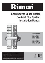
<strong>DX1000</strong><strong>In<strong>for</strong>mation</strong> <strong>Sheet</strong> <strong>for</strong> <strong>Builders</strong> <strong>and</strong> <strong>Architects</strong>For further in<strong>for</strong>mation or specifications, visit the technicalsection of our website www.escea.com to view the latestproduct Installation Manual.Appliance <strong>In<strong>for</strong>mation</strong>Product Dimensions74466418361372Gas SpecificationsHeat OutputGas Input / ConsumptionGas ConnectionGas TypeOperating PressureInlet Gas PressurePower Requirement8kW*33MJ/hr*Lower right side of appliance, 1/2” BSPNatural Gas / LPG (NZ) / Propane (Aus)0.76kPa NG / 1.96kPa LPG or Propane1.13kPa to 5.0kPa NG2.75kPa to 5.0kPa LPG or Propane3 pin earthed 230V power outlet tobe within 1.0m of right side of theappliance132838270Cavity <strong>In<strong>for</strong>mation</strong>* Internal results pending confirmation from test laboratoryMinimum Cavity Dimensions (mm):The appliance must be installed priorto <strong>and</strong> behind the finished wall surface.Take into account any plaster board, tilesor any other finishing surface that maybe intended <strong>for</strong> the finished wall surface.Wall finishing materials must not encroachupon the minimum cavityclearances shown.The wall board that lines the outsideof the opening can be normal plasterboard <strong>and</strong> does not need to be noncombustible.<strong>800</strong>MIN1400MINFront450MINSideSingle Sided381SideDouble Sided400 MIN150 MIN1062 MIN<strong>800</strong>MIN1150 MIN192362Mantle Clearances (mm) ‘Hutch’ style cavity minimum dimensions (mm) Wall opening size <strong>for</strong> frameless / no fascia (mm)630231_1
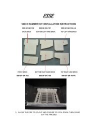
Flue <strong>and</strong> Duct <strong>In<strong>for</strong>mation</strong>Ducting in<strong>for</strong>mation:This gas fire features a small network of ducting situatedeither in the ceiling or under the floor to distribute the heatgenerated by this fireplace.Warm room air ducted to outlets#906660Escea DX DuctingCeiling Outlet Kit+6m Ø2503m Ø1503m Ø250FAN6m Ø150ExhaustIntake Air#906640Escea DX DuctingFan UnitFIRE3m Ø150#906650Escea DX DuctingFlooring Outlet Kit6m Ø2503m Ø1503m Ø250FAN6m Ø150+#906640Escea DX DuctingFan UnitFIRE3m Ø150#906661Escea DX DuctingExtension Kit6m Ø2503m Ø1503m Ø150Flue in<strong>for</strong>mation:There are two basic types of flue configuration, using avertical powerflue cowl, or a horizontal powerflue cowl. Thehorizontal offset of the terminal can be any amount up to thetotal flue length shown. You cannot flue down, ie allow theterminal to be lower than the outlet on the appliance.10m MAXXYX + Y = 12m MAX= 0.6m MINCavity Size <strong>for</strong> Horizontal Powerflue:When cutting the hole in the outside wall, be mindful of how the installationHorizontal Powerflue Wall Terminal will be finished, the installation must beweatherproof.Ideal hole/cavity size <strong>for</strong> Horizontal PowerflueX298mmY298mmZ175mm* Note, Z dimension does not include allowance <strong>for</strong> flue which exists hereas shown in the above diagrams. If the flue is exiting the powerflue <strong>and</strong> immediatelygoing downwards, Z dimension will need to be at least 400mm toallow <strong>for</strong> the flue <strong>and</strong> flue bend radius.630231_1