BRLM, BRUD Manual text - StoneAge Inc
BRLM, BRUD Manual text - StoneAge Inc
BRLM, BRUD Manual text - StoneAge Inc
- No tags were found...

You also want an ePaper? Increase the reach of your titles
YUMPU automatically turns print PDFs into web optimized ePapers that Google loves.
LANCING SYSTEM<strong>BRLM</strong> AND <strong>BRUD</strong>OPERATION AND MAINTENANCEMANUALW A T E R J E T T O O L S02/0654 GIRARD ST. DURANGO, COLORADO 81303 970-259-2869 PHONE 970-259-2868 FAXwww.stoneagetools.com sales@stoneagetools
TABLE OF CONTENTS1.0 INTRODUCTION2.0 SAFETY WARNING3.0 DESCRIPTION4.0 SPECIFICATIONS5.0 ASSEMBLY INSTRUCTIONS6.0 OPERATION AND MAINTENANCE7.0 PARTS LISTS AND ASSEMBLY DRAWINGS8.0 WARRANTYAPPENDIXA. AIR MOTORSB. HYDRAULIC MOTORC. REGULATOR1.0 INTRODUCTIONThis manual was prepared to provide the operator with the basic information needed to operate andservice this equipment. The operating recommendations in the manual will ensure that you receivesatisfactory performance. All operating personnel responsible for the care of this equipment should befamiliar with the information in this manual.If you have any questions or problems with this equipment, please contact the distributor you obtained theproduct from, or the manufacturer:<strong>StoneAge</strong>, <strong>Inc</strong>.54 Girard St.Durango, CO 81303970-259-2869 Phone 970-259-2868 Faxwww.stoneagetools.com2.0 SAFETY WARNINGOperations with this equipment can be potentially dangerous if caution is not exercised prior to and duringtool use. Please read and follow all of these instructions, in addition to the guidelines in the WJTARecommended Practices handbook.2.1 Only competent and trained persons should operate this equipment.2.2 The immediate work area should be marked off to keep out untrained persons.2.3 All personnel in the area should wear appropriate personal protective equipment.2.4 Inspect the equipment for visible signs of deterioration, damage, or improper assembly.Do not operate until repaired. Make sure all threaded connections are tight and leak free.2.5 Check nozzle orifices before use. If any are plugged, they must be cleaned or replaced.2.6 The machine should be securely supported. Strong thrust is created by waterjets.2.7 This equipment should always be used with an operator controlled dump mechanism torelease the high pressure water. If it is necessary to have a person work near thecleaning jets, then it is this person who should have control of the pressure dump.2.8 Check that all control functions work properly before going to high pressure.2.9 Do not exceed the maximum operating pressure specified for any component in a system.
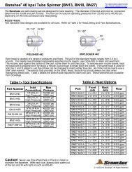
3.0 DESCRIPTIONThis Lancing System was designed to effectively clean tubes in heat exchangers and evaporators. It isused with a rigid lance and nozzle tip. The water exits through small orifices in the nozzle tip as highvelocity waterjets that are capable of unplugging and removing scale in tubes. Air or hydraulic motorssupply rotation and feed power.Since the lances are continuously rotated, a fewer number of larger, more powerful jets are used tocompletely clean the insides of the tubes. Larger jets will also penetrate tougher deposits more effectivelythan many smaller, non-rotating jets. Rotation of the tip also makes this tool effective for polishing tubewalls. Nozzle tips with cutting edges can also be used to combine the advantages of mechanical cuttingwith waterblasting. The powered feed allows all the jet power to be used in attacking the material ahead ofthe tip.4.0 SPECIFICATIONSStandard Rail Length <strong>BRLM</strong> 300-15Standard Extensions <strong>BRLM</strong> 080-x15ft5, 10, 15, 20 or 25 ftStroke Length Total Rail Length 15 ft 20 ft 25 ft 30 ft 35 ft 40 ftStroke Length 12.5 ft 17 ft 22 ft 26.5 ft 31.5 ft 36 ftLance Guide Blocks Total Rail Length 15 ft 20 ft 25 ft 30 ft 35 ft 40 ftNumber of Guides 4 6 7 8 9 10Carriage Packages <strong>BRLM</strong> 310 Single Rotary 15,000 psi<strong>BRLM</strong> 320 Single Rotary 20,000 psi<strong>BRLM</strong> 330 Single Rotary 40,000 psi<strong>BRLM</strong> 340 Dual Rotary 15,000 psi<strong>BRLM</strong> 350 Dual Rotary 20,000 psi<strong>BRLM</strong> 360 Dual Rotary 40,000 psi<strong>BRLM</strong> 370 4 Lance Non-Rotary 15,000 psi<strong>BRLM</strong> 380 4 Lance Non-Rotary 20,000 psiWater Swivels Pressure 15,000 psi 20,000 psi 40,000 psiSingle Rotary SG-P8P8-0 SG-M12AV12-0 UH-H6H9Dual Rotary SL-P8P4-0 SL-M9AV9-0 UH-H6H94 Lance Non-Rotary SG-P12P12M-90 SG-M12AV12-90Lance Connection Pressure 15,000 psi 20,000 psi 40,000 psi1/8 and 1/4 npt 3/8 and 9/16 MP 3/8 and 9/16 HPRotation Air Motor Gast 4AM 20 to 40 cfm @ 80 psiFeed Air Motor Gast 6AM 30 to 50 cfm @ 80 psi
<strong>BRLM</strong> DRIVE ASSEMBLY INSTRUCTIONS1. There are three possible locations for the feed drive gearbox. These positions allow for clearance ofchannel heads or other obstructions.2. Choose the desired location (the drive gearbox will be centered between two slots) and feed atape measure down thru the rear slot selected out to the end of the rail.Use a piece of wire to attach one chain end to the tape measure, and pull the chain out thru the slot.3. Feed the tape measure in thru the front of the rail to the front slot selected; attach the chain to thetape measure and pull the chain end out of the rail.Wedge Bolt AssyChain4. Feed chain over sprocket on the FrontIdler Assembly; install the front idler assemblyin the rail and secure with a Wedge Bolt Assy.The flat edges of the wedge bolt should beparallel with the top and bottom of the rail.Rear Idler Assy5. Repeat these steps for the Rear Idler Assy.chain over drive sprocketWedge Bolt AssyFront Idler AssyTensioner Nut on Front Idler AssyRail Clamps6. Remove the chain guard from the feed drive gearbox.7. Remove two of the rail clamps and loosen the other two.8. Pull up on the loop of chain and slide the feed drive gearbox onto the rail,routing the chain over the drive sprocket and under the idler sprockets.9. Equally space the idler sprockets over the slots; install and tighten rail clamps; install the Chain Guard.10. Flip the rail over and connect the chain ends with the master link.11. Tighten chain with Tensioner Nut; on a 20 foot rail, ten pounds of pull in the center of the chain should raise it 8 inches.01/04
<strong>BRLM</strong> ASSEMBLY OF GUIDES AND CARRIAGE ONTO RAILRear Idler GuardChain HookAttach Guide Coilto CarriageAttach Guide Coilusing <strong>BRLM</strong> 036Slotted Bolt (maxtorque 20 ft-lb)1. Remove the rear idler guard from the rail assembly;remove the Chain Hook from the carriage assembly.2. Slide the guide blocks onto the rail assembly, followedby the carriage assembly, both from the rear of the rail assembly.3. Attach the cable coil to the carriage and to the front idler assembly using the slotted anchor bolts.4. Attach the carriage to the chain using the chain hook. The chain hook must be rotated as it is installedso that it properly engages into a link in the chain.5. Install the rear idler guard.clamp blocks for high pressure hosetail chainswivel bracketfront guide platecarriage stop6. install the swivel bracket and tail chain to the carriage.7. Extend the tail chain straight back; with tail chain in this positionclamp high pressure water hose with clamp blocks.9. Install the carriage stop with the rail clamps forward.10, Install the front guide plate and desired type of splash guard to the frontof the machine.01/04
<strong>BRUD</strong> ASSEMBLY INSTRUCTIONSStep #14) Fit the cross tube into the frame rails and secure withwedge bolt assemblies (note the orientation of thewedge bolts - expansion in the direction to pull the tubeand frame together).TOOLS REQUIRED:(2) 9/16" wrenches(2) 1/2" wrenches(1) 3/16" allen rwrench(1) Tape measure2) Feed the vertical frame rails between the rollers onthe carrier assembly.NOTE: The gearboxes, Z scew clamp, andY screw clamps are all on the same side ofthe assembly.1) Support the carrier assembly with blocks/saw horses/etc.Place a cross tube on the ground below the carrier assembly.3) Fit the cross tube into the frame rails. Securewith wedge bolt assemblies (note the orientationof the wedge bolts - expansion in the direction topull the tube and frame together).07/04
<strong>BRUD</strong> ASSEMBLY INSTRUCTIONSStep #28) Secure the Y-screws at the topand bottom with the screw clamps(4X) and 3/8 bolts.7) Feed the screws throughuntil the top of the screw isflush with the top of the'U-Shaped' mounting block.6) Feed the Y screws (vertically) through the rightangle gear boxes (hold the screws by hand andfeed through by turning the crank handle.NOTE: The distance from the top of the carrierside plate to the top of the vertical frame railshould be the same on both sides of the unit. Ifthe distance varies more than 1/8", from oneside to the other, loosen one of the Y screws andmove it up or down (by hand) and retighten at theproper height.5) Insert 1/2" Ø bolts/pins into holes in verticalframe rails (on the inside). Allow the carrierassembly to rest on the pins during the remainderof the assembly process.10) Attach axle assemblies (widened outat least 12" per side) to frame structureand secure with 3/8 Ø bolts. The carriercan be moved up or down with the handcranks to help align the cross tube andaxle assemblies.NOTE: The axles should be extended outfor lancing operations and retracted fortransportation or storage.07/04
<strong>BRUD</strong> ASSEMBLY INSTRUCTIONSStep #3Attach support bars and clamps to front of<strong>BRUD</strong> (side opposite the Y screws).The Z clamp attaches to the lancing machine box rail.After the lancing machine (<strong>BRLM</strong>) is mounted, clampthe end of the Z screw into the rear of the carriage.Turning the hand crank moves the lancing machinein the Z direction.If the hand crank feels 'rough' or is difficult to turn(for the vertical motion) loosen the four bolts holdingthe assembly to the carrier plate and the four boltsholding the gear box/mounting plate together. Dothis on both sides of the carrier. With all of the boltsloose, turn the handle several revolutions. This willhelp to align the gear boxes and eliminate bindingparts. Retighten all bolts afterwards.To attach the lancing machine (<strong>BRLM</strong>), loosen the carraige clamps (3X), allowingthe rollers to spread apart on the carriage. Set the lancing machine rail between therollers and close the rollers by tightening the three handles in unison. Make sure thecarriage frame is fully closed (front to rear) to keep the lancing machine secure.07/04
<strong>BRUD</strong> VERTICAL OPERATION1) Remove both axle assembliesfrom the <strong>BRUD</strong> Frame.2) Insert 2" Ø scaffolding throughbothcross tubes. Both of thesepipes should be supported byscaffolding. By supporting in thismanner, the <strong>BRUD</strong> assembly canbe moved about on the scaffoldingto the desired position.The <strong>BRUD</strong> can be operated either manually (with hand cranks) or with airpower. In either case, proper scaffolding will be required to support theoperator(s) and additional equipment (i.e. control box, dump valves,hoses, etc.)Follow the same <strong>BRLM</strong> installation instructions as in the horizontal orientation.07/04
<strong>BRUD</strong> AIR UPGRADENOTE: The air motors and gearboxes can be installed on either endof the <strong>BRUD</strong>. It is a matter of user preference and convenience.The gearboxes can go on either side, but the air motors should alwaysbe facing out.1) Install torque block (<strong>BRUD</strong> 068)with bushing (<strong>BRUD</strong> 065) to bothend plates in this location.2) Loosen clamps securing hand crank handlesand remove the handles.Bushing3) Insert the shaft on the gear box into the clamp(where the handles were removed) and align the torquearm with the bushing. Retighten the clamps to securethe gearbox/air motor assemblies.NOTE: This is showing the scenario wherethe X configuration gearbox/air motoris attached to the Y configuration spot.TorqueArmNOTE: There are three different configurations of the gearbox on the <strong>BRUD</strong>assembly. The X-configuration is used to control movement along theX-axis. The Y-configuration is used to control movement along the Y-axis.The X and Y configurations will be switchable depending on the side they arebeing attached to. The Z-configuration is used to control movement alongthe Z-axis and can only be attached to the sliding carriage frame (<strong>BRUD</strong> 082).X-configuration Y-configuration Z-configuration07/04
6.0 OPERATION AND MAINTENANCEThe <strong>BRLM</strong> Tube Lancing System is simple to operate but some care is necessary for safe and productiveuse. Please read and follow all of these recommendations.AIR SUPPLYA compressed air source of at least 70 cfm at 80 psi is required. Lower pressure will result inslower rotation and feed rates. Blow air through all hoses before connecting. A 3/4 inch diameter or largersupply hose is recommended. Keep the lubricator (on the Control Box) filled with air tool oil. It should beset to drip 6 to 8 drips per minute of oil.CONTROL BOXThe standard Control Box has an air inlet port and three outlets that need to be connected to themachine. One connects to the rotation motor and two go to the feed motor. Make sure the hoses areattached correctly and all controls function properly before beginning operation. Two regulators are usedto control the feed rate; one controls forward feed and the other the retract speed.LANCESelect the diameter and length of lance for each particular job. It is recommended that highstrength alloy be used instead of standard pipe grades; 3/8 tubing can be threaded for 1/8 pipe, and 9/16tubing can be threaded for 1/4 pipe. The material selected should have adequate wall thickness for thepressure being used. Lances with larger inside diameters will minimize pressure drop at higher flows, butrequire larger wall thickness to contain the same pressure. Always flush the lance thoroughly beforeattaching a nozzle tip.NOZZLE TIPBecause the lance and tip rotate, the nozzle tip will typically have a small number of jets (3 to 5).This allows large jet sizes to be used for more effective cleaning. Most nozzle tips can be used includingspecial bits with cutting edges, nozzle inserts, etc. Be sure to select a tip that matches the pressure andflow to be used.CARRIAGEThe water swivel, gearbox and rotation motor are mounted on the moving carriage. A chain hookattaches the drive chain to the carriage. The carriage rolls on rollers with bearings; each roller has agrease zerk on the axle bolt, and should be greased periodically. The carriage can be removed from therail by removing the chain hook, rear stop and rear chain guard.RAILThe lance rail should be kept clean. Do not apply any lubrication to the rail, as this tends to collectgrit and increase wear.CHAINThe chain is type C2040. Spray with a light oil occasionally to prevent corrosion. The chain istensioned by a take-up bolt connected to the idler. The tension can be set when the carriage is all the wayback and 20 ft of chain is exposed. Ten pounds of pull in the middle of the chain should raise the chainabout 5 inches.GUIDE BLOCKSThe lance guide blocks slide on the frame rails and provide support for the rotating lance. Theguides are pushed forward by the carriage as it comes to each one. A wire rope coil is attached to eachguide and the carriage. When the carriage is pulled back, the guides will be pulled back by the coil. Theanchor bolts (<strong>BRLM</strong> 036) that attach the coil to the carriage and front plate should not be tightened tomore than 20 ft-lb. A stationary front snout is used to locate the bit for entry into the tube. An extensioncan be added by screwing in a 1 inch pipe nipple. Vacuum collection of water and cuttings can beaccomplished by installing a pipe tee to the front guide. When using the dual lance arrangement, the frontguides should be spaced to match the tube spacing.
7.0 PARTS LISTS AND ASSEMBLY DRAWINGS<strong>BRLM</strong> 300-15 Box Rail and DriveBR 008 Wedge Bolt Assembly 2BR 010 Rear Idler Bracket 1BR 011.1 Lifting Eye 1BR 011.2 Bolt, Lifting Eye 1BR 011.3 Roll Pin 1BR 026 Idler Bolt 1BR 030 Idler Plate 1BR 060 Rail Clamp 6BR 133 Chain Guard 1BR 137 Chain Guard, rear 1BR 156 Muffler, 3/4 pipe 2BR 170-B18.1 Gearbox, Bonfiglioli 1BR 172 Shaft, Drive Sprocket 1BR 173 Retaining Ring 1<strong>BRLM</strong> 005-XX Rail, 15 ft 1<strong>BRLM</strong> 020-WP Chain, C2040WP 31 ft<strong>BRLM</strong> 021 Connecting Link, Chain 3<strong>BRLM</strong> 032 Front Bracket 1<strong>BRLM</strong> 033 Guide Stop 2<strong>BRLM</strong> 051 Drive Plate 1<strong>BRLM</strong> 052 Idler Mount 2<strong>BRLM</strong> 070 Carriage Stop 1LM 016-6 Air Motor, Gast 6AM 1LM 018 Drive Sprocket 1LM 022.1 Idler Sprocket 2LM 025.1 Idler Sprocket 2LM 025.2 Swing Bolt 1ML 017-8.1 Quick Exhaust Valve 2ML 017-8.4 Nipple, 1/2 x 1 1ML 017-8.7 Nipple, 1/2 x 4 1ML 017-8.8 Fitting, P8J8 x 45 2UD 045-D Spacer, Aluminum 3<strong>BRLM</strong> 080-X Box Rail ExtensionBR 004.1-X Rail Extension, X ft 1BR 006-N Splice Tube 1BR 008 Wedge Bolt Assembly 2<strong>BRLM</strong> 020-WP Chain, C2040WP 2 x X ft<strong>BRLM</strong> 034-X Coil, X ft 1<strong>BRLM</strong> 035-10 Guide Block, Single OR X/3<strong>BRLM</strong> 039-10 Guide Block, Dual or Multi X/3<strong>BRLM</strong> 037 Clamp, Coil X/3
<strong>BRLM</strong>-300 BOX RAIL AND DRIVE PACKAGE<strong>BRLM</strong> 011.3Roll PinBR 137Guard, IdlerUD 045-D (2)SpacerBR 011.2Bolt, Lifting Eye<strong>BRLM</strong> 020-WPChain<strong>BRLM</strong> 300-H (HYDRAULIC) OPTIONLM 123 (2)Fitting, Hyd.LM 122Motor, Hyd.BR 011.1Lifting EyeBR 010Rear IdlerWeldment<strong>BRLM</strong> 005-XXDrive RailLM 120Adaptor, Hyd.BR 008 (2)Wedge BoltBR 060 (6)Rail Clamp<strong>BRLM</strong> 070Stop, CarriageLM 022.1 (2)Idler SprocketBR 156 (2)MufflerML 017-8.1 (2)Quick ExhaustValve<strong>BRLM</strong> 051Mid Drive PlateLM 025.1 (2)Idler SprocketUD 045-DSpacerBR 026Bolt<strong>BRLM</strong> 033Guide StopML 017-8.7NippleLM 016-6Air MotorBR 133Chain Guard<strong>BRLM</strong> 056Idler MountLM 018SprocketBR 172Shaft, Drive Sprocket<strong>BRLM</strong> 032Front BracketLM 025.2Swing BoltBR 030Idler PlateML 017-8.4NippleML 017-8.8 (2)Fitting, ElbowBR 173Retaining RingBR 170-B18.1Gearbox07/04
<strong>BRLM</strong> 080-X RAIL EXTENSION KIT<strong>BRLM</strong> 035-XX - Specify Style (Single Rotary, Dual Rotary, 4ML, 8ML)Quanity Dependent on Length of Extension, (approximately 1 every 3 ft)<strong>BRLM</strong> 034-XXCOIL<strong>BRLM</strong> 037CLAMP, COIL<strong>BRLM</strong> 020-WPCHAINBR 004-XXRAIL EXTENSIONBR 008 (2)BOLT, WEDGE ASBR 006-NTUBE, SPLICE07/04
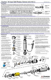
<strong>BRLM</strong> 310-15, 320-15 and 330-15 Single RotaryAF 071-H6 ♣ Collar, 3/8 HP 1AF 071-H9 ♣ Collar, 9/16 HP 1AF 071-M6 ♦ Collar, 3/8 MP 1AF 071-M9 ♦ Collar, 9/16 MP 1AF 072-H6 ♣ Gland, Antivibe 1AF 072-H9 ♣ Gland, Antivibe 1AF 072-M6 ♦ Gland, Antivibe 1AF 072-M9 ♦ Gland, Antivibe 1AF 073-H6 ♣ Coupler 1AF 073-H6H9 ♣ Coupler 1AF 073-M6M12 ♦ Coupler 1AF 073-M9M12 ♦ Coupler 1BR 052-2.5 Axle with Zerk 4BR 055 Roller 4BR 155 Muffler, 1/2 pipe 1BR 157 Fitting, P8J8 1BR 190-B7 Gearbox 1<strong>BRLM</strong> 018 Coil Mount Plate 1<strong>BRLM</strong> 019 Chain Hook 1<strong>BRLM</strong> 022 Carriage Plate 1<strong>BRLM</strong> 027-SGS •♦ Bracket, Swivel, Tail 1<strong>BRLM</strong> 027-JES ♣ Bracket, Swivel, Tail 1<strong>BRLM</strong> 034-15-D Coil 1<strong>BRLM</strong> 035-10 Guide Block, Single 4<strong>BRLM</strong> 036 Bolt, Anchor Coil 1<strong>BRLM</strong> 037 Clamp, Coil 4<strong>BRLM</strong> 040-1 Front Plate 1<strong>BRLM</strong> 150 Splash Guard 1<strong>BRLM</strong> 160 Fitting, Tee 1<strong>BRLM</strong> 170 Nipple 1<strong>BRLM</strong> 270 Clamp, Hose 2<strong>BRLM</strong> 271 Plate, Hose Clamp 1<strong>BRLM</strong> 272 Tail End Plate 1<strong>BRLM</strong> 273 Tail Chain 1<strong>BRLM</strong> 275 Hose, Tail Cover 1GP 075-375 Collet, 3/8 MP and HP lance 3GP 075-406 • Collet, 1/8 pipe lance 3GP 075-547 • Collet, 1/4 pipe lance 3GP 075-562 Collet, 9/16 MP and HP lance 3GP 076 Collet Nut 3LM 012-06 Front Bushing, .40 ID 1LM 012-09 Front Bushing, .60 ID 1LM 014 Nipple 1LM 016-4 Air Motor, Gast 4AM 1SA 056-P8P2 • Adaptor, 1/8 pipe lance 1SA 056-P8P4 • Adaptor, 1/4 pipe lance 1SG 600 •♦ Service Kit 1SG P8P8-0 • Swivel, 15 ksi 1SG M12AV12-0 ♦ Swivel, 20 ksi 1UH 600 ♣ Service Kit 1UH-H6H9 ♣ Swivel, 40 ksi 1• <strong>Inc</strong>luded with 15,000 psi assembly only (<strong>BRLM</strong> 310-15)♦ <strong>Inc</strong>luded with 20,000 psi assembly only (<strong>BRLM</strong> 320-15)♣ <strong>Inc</strong>luded with 40,000 psi assembly only (<strong>BRLM</strong> 330-15)
<strong>BRLM</strong> 310 SINGLE ROTARY 15 KSISA 056-P8P4SA 056-P8P2Adapter, 1/4 and 1/8 NPTSG-P8P8SwivelBR 194Key (2)BR 190-B7GearboxBR 192ShaftBR 155MufflerBR 157FittingLM 016-4Air MotorBR 193Jam nut<strong>BRLM</strong> 310-H (Hydraulic) ComponentsLM 123Fittings (2)LM 122Hydraulic Motor<strong>BRLM</strong> 273Tail Chain<strong>BRLM</strong> 271Plate, Clamp<strong>BRLM</strong> 270Clamp (2)<strong>BRLM</strong> 272Plate, TailGP 075-375 (3)GP 075-562 (3)Collets, 3/8 and 9/16"GP 076Collet Nut (3)LM 120Adapter Plate, Hyd<strong>BRLM</strong> 027-SGSSupport<strong>BRLM</strong> 022Carriage<strong>BRLM</strong> 019Chain Hook<strong>BRLM</strong> 018Coil Mount<strong>BRLM</strong> 034-xxCoil<strong>BRLM</strong> 035-xxSingle Guide Block(4 used with 15 ft rail)LM 012BushingLM 014Nipple<strong>BRLM</strong> 160Tee<strong>BRLM</strong> 150Splash GuardBR 055Roller (4)BR 052-2.5Axle (4)<strong>BRLM</strong> 037Clamp, Coil<strong>BRLM</strong> 036Bolt, Coil Anchor (2)<strong>BRLM</strong> 170Nipple<strong>BRLM</strong> 040-1Front Plate07/04
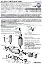
<strong>BRLM</strong> 320 SINGLE ROTARY 20 KSISG M12-AV12SwivelAF 072-M6AF 072-M9AV Gland (1 of each)BR 194Key (2)BR 190-B7GearboxBR 192ShaftBR 155MufflerBR 157FittingLM 016-4Air Motor<strong>BRLM</strong> 320-H (Hydraulic) componentsLM 123Fitting (2)AF 073-M6M12AF 073-M9M12Coupling (1 of each)AF 071-M6AF 071-M9Collar (1 of each)<strong>BRLM</strong> 273Tail Chain<strong>BRLM</strong> 270Clamp (2)<strong>BRLM</strong> 271Plate, ClampBR 193Jam NutGP 075-375 (2)GP 075-562 (2)Collets, 3/8 and 9/16"GP 076Collet Nut (2)LM 120Plate, AdapterLM 122Hydraulic Motor<strong>BRLM</strong> 272Plate, Tail<strong>BRLM</strong> 019Chain Hook<strong>BRLM</strong> 027-SGSSupport<strong>BRLM</strong> 018Coil Mount Plate<strong>BRLM</strong> 034-xxCoil<strong>BRLM</strong> 035-xxSingle Guide Block(4 used with 15 ft rail)LM 012BushingLM 014Nipple<strong>BRLM</strong> 022Carriage<strong>BRLM</strong> 170Nipple<strong>BRLM</strong> 160TeeBR 055Roller (4)BR 052-2.5Axle (4)<strong>BRLM</strong> 037Clamp, Coil<strong>BRLM</strong> 036Bolt, Coil Anchor (2)<strong>BRLM</strong> 040-1Front Plate<strong>BRLM</strong> 150Splash Guard07/04
<strong>BRLM</strong> 330 SINGLE ROTARY 40 KSIUH-H9H6SwivelAF 073-H6H9CouplerAF 072-H9Gland NutBR 157FittingLM 016-4Air Motor<strong>BRLM</strong> 330-H (Hydraulic) OptionLM 123 (2)Fitting<strong>BRLM</strong> 271Plate, Hose Clamp<strong>BRLM</strong> 270 (2)Clamp, Hose<strong>BRLM</strong> 272Plate, Tail EndBR 155MufflerGP 075-562ColletGP 076Collet NutLM 122Motor, Hyd.LM 120Adaptor, Hyd. MotorBR 192Shaft, Hollow<strong>BRLM</strong> 019Chain HookBR 190-B7Gearbox, Bonfig.<strong>BRLM</strong> 018Coil Mount Plate<strong>BRLM</strong> 034-XXCoil<strong>BRLM</strong> 035-XXSingle Guide Block<strong>BRLM</strong> 275Cover, Tail Chain<strong>BRLM</strong> 027-JESBracket, TailLM 012Bushing, FrontLM 014Nipple<strong>BRLM</strong> 150Splash Guard<strong>BRLM</strong> 022Plate, Carriage<strong>BRLM</strong> 036Bolt, Coil AnchorBR 052-2.5 (4)AxleBR 055 (4)Roller AssemblyFS 004-0° (4)Zerk, Straight<strong>BRLM</strong> 037Clamp, Coil<strong>BRLM</strong> 040-1Front Plate<strong>BRLM</strong> 170P16 Nipple07/04<strong>BRLM</strong> 160P16 Tee
<strong>BRLM</strong> 340-15, 350-15 and 360-15 Dual RotaryAF 061-M6 ♦ Adapter, M to 3/8 MP 2AF 061-M9 ♦ Adapter, M to 9/16 MP 2AF 061-P4 • Adapter, M to 1/4 pipe 2AF 061-P8 • Adapter, M to 1/2 pipe 2AF 070-H6 ♣ Gland, 3/8 HP 2AF 070-H9 ♣ Gland, 9/16 HP 2AF 071-H6 ♣ Collar, 3/8 HP 4AF 071-H9 ♣ Collar, 9/16 HP 4AF 071-M6 ♦ Collar, 3/8 MP 2AF 071-M9 ♦ Collar, 9/16 MP 2AF 072-H6 ♣ Gland, Anti-vibe 2AF 072-H9 ♣ Gland, Anti-vibe 2AF 072-M6 ♦ Gland, Anti-vibe 2AF 072-M9 ♦ Gland, Anti-vibe 2AF 073-H6 ♣ Coupler 2AF 073-H6H9 ♣ Coupler 2AF 073-M6M9 ♦ Coupler 2AF 073-M9 ♦ Coupler 2BR 052-2.5 Axle with Zerk 4BR 055 Roller 4BR 155 Muffler, 1/2 pipe 1BR 157 Fitting, P8J8 1<strong>BRLM</strong> 018 Coil Mount Plate 1<strong>BRLM</strong> 019 Chain Hook 1<strong>BRLM</strong> 022 Carriage 1<strong>BRLM</strong> 024-D Pedestal, Plate 1<strong>BRLM</strong> 027-JED ♣ Bracket, Swivel, Tail 1<strong>BRLM</strong> 027-SLD •♦ Bracket, Swivel, Tail 1<strong>BRLM</strong> 034-15-D Coil 1<strong>BRLM</strong> 036 Bolt, Anchor Coil 1<strong>BRLM</strong> 037 Clamp, Coil 4<strong>BRLM</strong> 039-10 Guide Block, Multi 4<strong>BRLM</strong> 041 Multi Channel 1<strong>BRLM</strong> 101 Dual Gearbox 1<strong>BRLM</strong> 266 ♣ Hose, Tail, 40 ksi 2<strong>BRLM</strong> 268 •♦ Hose, Tail, 15 and 20 ksi 2<strong>BRLM</strong> 269-15K • Manifold, Tail Y 1<strong>BRLM</strong> 269-20K ♦ Manifold, Tail Y 1<strong>BRLM</strong> 269-40K ♣ Manifold, Tail Y 1<strong>BRLM</strong> 272 Tail End Plate 1<strong>BRLM</strong> 273 Tail Chain 1<strong>BRLM</strong> 275 Hose, Tail Cover 1GP 075-375 Collet, 3/8 tubing 4 (6 for 15K)GP 075-406 • Collet, 1/8 pipe Lance 6GP 075-547 • Collet, 1/4 pipe Lance 6GP 075-562 Collet, 9/16 tubing 4 (6 for 15K)GP 076 Collet Nut 4 (6 for 15K)ML 072-P2 Guide Tube, 1/8 pipe and 3/8 tubing 2ML 072-P4-L Guide Tube, 1/4 pipe and 9/16 tubing 2ML 072.1 Spring Nut 2SA 056-P4P2 • Adapter, 1/8 pipe Lance 2SA 056-P4P4 • Adapter, 1/4 pipe Lance 2SG 055 Air Motor, Gast 4AM 1SL 600-K ♦ Service Kit, 20 ksi 2SL 600-P • Service Kit, 15 ksi 2SL M9AV9 -0 ♦ Swivel, 20 ksi 2SL P8P4-0 • Swivel, 15 ksi 2UH 600 ♣ Service Kit, 40 ksi 2UH H6H9 ♣ Swivel, 40 ksi 2• <strong>Inc</strong>luded with 15,000 psi assembly only (<strong>BRLM</strong> 340-15)♦ <strong>Inc</strong>luded with 20,000 psi assembly only (<strong>BRLM</strong> 350-15)♣ <strong>Inc</strong>luded with 40,000 psi assembly only (<strong>BRLM</strong> 360-15)
<strong>BRLM</strong> 340 DUAL ROTARY 15 KSI<strong>BRLM</strong> 268-002 (2)HOSE ASSY<strong>BRLM</strong> 340-H (HYDRAULIC) OPTIONLM 123 (2)FITTING<strong>BRLM</strong> 273CHAIN, TAIL AF 061-P4 (2)FITTING<strong>BRLM</strong> 269-15KMANIFOLDLM 122MOTOR, HYDBR 157MUFFLERBR 167CAP, DUST<strong>BRLM</strong> 127MOUNT, HYD<strong>BRLM</strong> 275COVER, CHAIN<strong>BRLM</strong> 272PLATE, TAIL END<strong>BRLM</strong> 027-SLDBRACKET, TAILBR 157FITTINGSG 055MOTOR, AIRAF 061-P8 (2)FITTINGSL-P8-P4-0° (2)SWIVELSA 056-P4-P2 (2)SA 056-P4-P4 (2)ADAPTER, LANCE<strong>BRLM</strong> 019HOOK, CHAIN<strong>BRLM</strong> 101GEARBOX, DUALGP 017-375 (6)GP 017-562 (6)COLLETGP 076 (6)NUT, COLLET<strong>BRLM</strong> 125COUPLING<strong>BRLM</strong> 039-XXBLOCK, MULTI-GUIDE<strong>BRLM</strong> 037CLAMP, COIL<strong>BRLM</strong> 034COILML 072-P2 (2)ML 072-P4-L (2)GUIDE, TUBE07/04<strong>BRLM</strong> 022PLATE, CARRIAGEBR 055 (4)ROLLER ASSYBR 052 (4)BOLT, AXLEFS 004-0° (4)ZERK, GREASE<strong>BRLM</strong> 024-DPLATE, PEDESTAL<strong>BRLM</strong> 018MOUNT, COIL<strong>BRLM</strong> 036ANCHOR, COIL<strong>BRLM</strong> 041CHANNEL, MULTIML 072.1 (2)NUT, SPRING
<strong>BRLM</strong> 350 DUAL ROTARY 20 KSI<strong>BRLM</strong> 268-002 (2)Hose Assembly<strong>BRLM</strong> 273Chain, tailAF 061-M6 (2)FittingBR 155Muffler<strong>BRLM</strong> 269-20KManifold<strong>BRLM</strong> 272Plate, Tail End<strong>BRLM</strong> 350-H (Hydraulic) OptionLM 123 (2)Fitting, Hyd<strong>BRLM</strong> 127Mount, HydLM 122Motor, Hyd<strong>BRLM</strong> 275Cover, Chain<strong>BRLM</strong> 027-SLDBracket, TailAF 061-M9FittingBR 167Cap, DustBR 157FittingGP 075-375 (4)GP 075-562 (4)ColletGP 076 (4)Nut, ColletSG 055Motor, Air<strong>BRLM</strong> 125Coupling<strong>BRLM</strong> 039-XXBlock, Multi-Guide<strong>BRLM</strong> 037Clamp, CoilSL-M9AV9-0° (2)SwivelAF 073-M6 (2)AF 073-M9 (2)CouplingAF 072-M9Gland, Antivibe<strong>BRLM</strong> 101Gearbox, Dual<strong>BRLM</strong> 019Hook, Chain<strong>BRLM</strong> 022Plate, Carriage<strong>BRLM</strong> 018Mount, Coil<strong>BRLM</strong> 036Anchor, Coil<strong>BRLM</strong> 024-DPlate, Pedestal<strong>BRLM</strong> 034CoilML 072.1 (2)Nut, SpringBR 055 (4)Roller AssemblyFS 004-0° (4)Zerk, Grease<strong>BRLM</strong> 041Channel, MultiML 072-P2 (2)ML 072-P4-L (2)Guide, LongBR 052 (4)Bolt, Axle07/04
<strong>BRLM</strong> 360 DUAL ROTARY 40 KSI<strong>BRLM</strong> 266Hose Assembly<strong>BRLM</strong> 273Chain, TailAF 070-H6 (2)GlandAF 071-H6 (2)Collar<strong>BRLM</strong> 269-40KManifoldBR 155MufflerBR 167Cap, Dust<strong>BRLM</strong> 360-H (Hydraulic) Option<strong>BRLM</strong> 127Mount, HydLM 123 (2)FittingLM 122Motor, Hyd<strong>BRLM</strong> 275Cover, Chain<strong>BRLM</strong> 027-JEDBracket, TailAF 070-H9 (2)Gland, AntivibeAF 071-H9 (2)CollarUH-H6H9 (2)SwivelAF 073-H6 (2)AF 073-H6H9 (2)CouplerAF 072-H6 (2)AF 072-H9 (2)Gland Nut, Antivibe<strong>BRLM</strong> 272Plate, Tail EndBR 157FittingGP 075-375 (4)GP 075-562 (4)ColletGP 076 (4)Nut, Collet<strong>BRLM</strong> 018Mount, Coil<strong>BRLM</strong> 036Anchor, Coil<strong>BRLM</strong> 125CouplingSG 055Motor, Air<strong>BRLM</strong> 039-XXBlock, Multi-Guide<strong>BRLM</strong> 037Clamp, Coil<strong>BRLM</strong> 034Coil<strong>BRLM</strong> 041Channel, MultiML 072.1 (2)Nut, Spring<strong>BRLM</strong> 101Gearbox, Dual<strong>BRLM</strong> 019Hook, Chain<strong>BRLM</strong> 022Plate, CarriageBR 055 (4)Roller AssemblyBR 052 (4)Bolt, AxleML 072-P2 (2)ML 072-P4-L (2)Guide, Tube<strong>BRLM</strong> 024-DPlate, PedestalFS 004-0° (4)Zerk, Grease07/04
<strong>BRLM</strong> 101 AND <strong>BRLM</strong> 101-H DUAL GEARBOX ASEMBLYBR 155MUFFLER<strong>BRLM</strong> 111 (2)RETAINERBR 167CAP, DUST<strong>BRLM</strong> 109 (4)BEARINGBR157FITTING<strong>BRLM</strong> 104 (2)SHAFT/GEARASSEMBLY<strong>BRLM</strong> 122SPACER<strong>BRLM</strong> 103COVER, SLOT<strong>BRLM</strong> 125COUPLINGSG 055MOTOR, AIR<strong>BRLM</strong> 107BEARING<strong>BRLM</strong> 115SCREW<strong>BRLM</strong> 100HOUSING<strong>BRLM</strong> 124SHAFT<strong>BRLM</strong> 105 (2)GEAR, WORMLM 123 (2)FITTINGLM 122MOTOR, HYD<strong>BRLM</strong> 113BEARING<strong>BRLM</strong> 110RETAINER, BLIND<strong>BRLM</strong> 127MOUNT, HYD<strong>BRLM</strong> 126COUPLING, HYD<strong>BRLM</strong> 101-H (HYDRAULIC) COMPONENTS02/06
<strong>BRLM</strong> 370-15 and 380-15 Multi-Lance Non-RotaryAF 071-M6 ♦ Collar, 3/8 MP 4AF 072-M6 ♦ Anti-vibe gland, 3/8 MP 4BR 052-2.5 Axle with Zerk 4BR 055 Roller 4<strong>BRLM</strong> 018 Coil Mount Plate 1<strong>BRLM</strong> 019 Chain Hook 1<strong>BRLM</strong> 022 Carriage Plate 1<strong>BRLM</strong> 024-ML Pedestal, ML 2<strong>BRLM</strong> 034-15-D Coil 1<strong>BRLM</strong> 036 Bolt, Coil Anchor 1<strong>BRLM</strong> 037 Clamp, Coil 4<strong>BRLM</strong> 039-10 Guide Block, Multi 4<strong>BRLM</strong> 041 Multi Channel 1<strong>BRLM</strong> 129 • Swivel Clamp 1<strong>BRLM</strong> 134 • Manifold, 4 port, 1/4 pipe 1<strong>BRLM</strong> 135 ♦ Manifold, 4 port, 3/8 MP 1GP 050 P12P12 • Elbow, P12 1ML 072-P2 Guide Tube, 1/8 pipe and 3/8 tubing 4ML 072-P4 Guide Tube, 1/4 pipe and 9/16 tubing 4ML 072.1 Spring Nut 4ML 077-P2 • Bushing, 1/4 to 1/8 pipe 4SA 366-P12P12-11.5 • Extension Nipple 1SG P12P12M-90 • Swivel, 15 ksi 1SG M12AV12-90 ♦ Swivel, 20 ksi 1• <strong>Inc</strong>luded with 15,000 psi assembly only (<strong>BRLM</strong> 370-15)♦ <strong>Inc</strong>luded with 20,000 psi assembly only (<strong>BRLM</strong> 380-15)
<strong>BRLM</strong> 370 NON-ROTARY FOUR LANCE 15 KSIGP 050-P12P12ELBOWSG-P12P12-M-90SWIVEL<strong>BRLM</strong> 129MOUNT, ML HOSESA 366-P12P12-11.5NIPPLE, EXTENSION<strong>BRLM</strong> 134-P12P4MANIFOLD<strong>BRLM</strong> 019HOOK,CHAINML 077-P2 (4)ADAPTER<strong>BRLM</strong> 039-XXBLOCK, MULTI -GUIDE<strong>BRLM</strong> 034COIL<strong>BRLM</strong> 022PLATE, CARRIAGE<strong>BRLM</strong> 037CLAMP, COIL<strong>BRLM</strong> 024-ML (2)PEDESTAL<strong>BRLM</strong> 018MOUNT, COIL<strong>BRLM</strong> 041CHANNEL, MULTIBR 055 (4)ROLLER ASBR 052 (4)BOLT, AXLEFS 004-0 (4)ZERK , GREASE<strong>BRLM</strong> 036 (2)ANCHOR, COILML 072.1 (4)NUT, SPRINGML 072-P2 (4)ML 072-P4-L (4)GUIDE, TUBE07/04
<strong>BRLM</strong> 380 NON-ROTARY FOUR LANCE 20 KSIAF 071-M12COLLARAF 072-M12FITTING, ANTIVIBESG-M12AV12SWIVEL<strong>BRLM</strong> 135MANIFOLD, 20KAF 071-M6 (4)COLLAR<strong>BRLM</strong> 019HOOK,CHAIN<strong>BRLM</strong> 022PLATE, CARRIAGEAF 072-M6 (4)FITTING, ANTIVIBE<strong>BRLM</strong> 039-XXBLOCK, MULTI -GUIDE<strong>BRLM</strong> 034COIL<strong>BRLM</strong> 041CHANNEL, MULTIBR 055 (4)ROLLER ASBR 052 (4)BOLT, AXLEFS 004-0 (4)ZERK , GREASE<strong>BRLM</strong> 036 (2)ANCHOR, COIL<strong>BRLM</strong> 037CLAMP, COIL<strong>BRLM</strong> 024-ML (2)PEDESTAL<strong>BRLM</strong> 018MOUNT, COILML 072.1 (4)NUT, SPRINGML 072-P2 (4)ML 072-P4-L (4)GUIDE, TUBE07/04
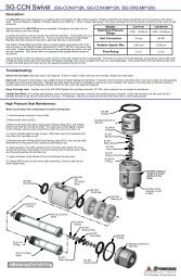
CB-2D Control Box, PneumaticCB 002 Frame 1CB 004-D Mounting Plate 1CB 006 Mounting Block 4CB 008 Screw 4CB 010 Rotation Plate, Bent 1CB 012-D Regulator Plate, Dual 1CB 020 Filter 1CB 022 Lubricator 1CB 023 Plate, Direction 1CB 024 Plate, End 1CB 026 Nipple, P6 2CB 052-14 Hose, 14 inch 1CB 052-18 Hose, 18 inch 1CB 054 Tee Fitting, P6 1CB 055 Cap 1CB 100 Frame 1CB 107 Leg Assembly 4CB 108 Leg Insert 4CB 109 Frame Support 1CB 110 Frame Arch 1CB 114 Inlet Fitting 1CB 115 Coupling, P8 1CB 116 Nipple, P8 1CB 120 Elbow Fitting, P6 90 1CB 122 Outlet Fitting, P6J8 2CB 124 Ball Valve 1CB 126 Outlet Fitting, Elbow, P6J8 90 5CB 132 Regulator 2CB 142 Valve, Selector 1CB 147 Elbow, P6P4 90 1CB 148 Gauge 1CB 158 Hose 3BR 154 Muffler 1CB 200 Upgrade Kit to Five Function (for <strong>BRUD</strong> Air)CB 008 Screw 4CB 050 Plate, Valve 1CB 052-14 Hose, 14 inch 3CB 056 Swivel Coupler P6 1CB 058 Cross Fitting P6 1CB 120 Elbow Fitting P6 90 3CB 122 Outlet Fitting P6J8 6CB 126 Outlet Fitting, Elbow P6J8 90 6CB 142-C Valve, Selector 3CB 158 Hose 6BR 154 Muffler 3
CB-2D CONTROL BOXCB 010RotationPlate, BentCB 024Plate, EndCB 023Plate, DirectionCB 022LubricatorCB 020FilterCB 012-DRegulator Plate, DualCB 124Ball ValveCB 002FrameCB 132RegulatorCB 108Leg InsertCB 004-DMounting PlateCB 148GaugeCB 110Frame ArchCB 142Valve, SelectorCB 109Frame SupportCB 107Leg AssemblyCB 200Upgrade KitCB-2D TO CB-5D CONVERSIONThis conversion is made to allow control ofan air powered <strong>BRUD</strong> assembly.STEP 2) Bolt the CB-5 conversionassembly onto the existing mountingblocks on the control box.STEP 3) Thread the swivelcoupling into the 4-waycoupler on the conversionassembly.CB 055Swivel CouplerSTEP 1) Remove cap (CB 055)from the T-fitting. Screw swivelcoupler (CB 056) on to T-fitting(in place of the cap).CB 055Cap07/04
<strong>BRUD</strong>-M-RS XY PositionerBR 008 Wedge Bolt Assembly 4BR 052-2 Axle with Zerk, 2 inch 8BR 052-3.25 Axle with Zerk, 3.25 inch 8BR 055 Roller 24<strong>BRUD</strong> 010 Handle, Tightening 5<strong>BRUD</strong> 011 Handle, Clamp 1<strong>BRUD</strong> 012 Gearbox 3<strong>BRUD</strong> 028 Z-Screw 1<strong>BRUD</strong> 029 Y-Screw 2<strong>BRUD</strong> 030 X-Screw 1<strong>BRUD</strong> 031 Coupling 2<strong>BRUD</strong> 032 Cross Shaft 1<strong>BRUD</strong> 034 Cross Shaft End 2<strong>BRUD</strong> 040 Handle, Crank 3<strong>BRUD</strong> 047 Flange Bearing 2<strong>BRUD</strong> 065 Bushing 3<strong>BRUD</strong> 070 Side Plate 2<strong>BRUD</strong> 072 Beam Insert 4<strong>BRUD</strong> 073 Beam Pin 4<strong>BRUD</strong> 074 Cross Beam 2<strong>BRUD</strong> 076 Frame Rail 2<strong>BRUD</strong> 077 X Nut 1<strong>BRUD</strong> 082 Carriage Assembly 1<strong>BRUD</strong> 084 Spring, Compression 5<strong>BRUD</strong> 100 Cross Tube 2<strong>BRUD</strong> 100.2 Clamp Half 5<strong>BRUD</strong> 110 Shaft 3<strong>BRUD</strong> 112 Collar 6<strong>BRUD</strong> 116 Nut Shaft Assembly 3<strong>BRUD</strong> 117 Spacer 12<strong>BRUD</strong> 120 Bracket 2<strong>BRUD</strong> 120.1 Plate 4<strong>BRUD</strong> 130 Z-Clamp 1<strong>BRUD</strong> 130.2 Z-Clamp Slider 2<strong>BRUD</strong> 140 Tube Clamp 4<strong>BRUD</strong> 141 J-Bolt 4<strong>BRUD</strong> 142 Wing Nut 4<strong>BRUD</strong> 145 Brace 4<strong>BRUD</strong> 156 Axle Bracket 2<strong>BRUD</strong> 158 Long Axle 4<strong>BRUD</strong> 172 Retaining Ring 8UD 060 C-Clamp 4UD 069 Hairpin 4UD 070-D Rear Top Bar 1UD 071-D Chain Hoist 1UD 072-D Trolley Assembly 1UD 073-D Rear Support Leg 4UD 080.1 Wheel 4UD 080.8 Hairpin 4<strong>BRUD</strong> 210 Air UpgradeBR 180-10:1 Gearbox 3BR 184 Arm, Torque 3<strong>BRUD</strong> 066 Bushing 1<strong>BRUD</strong> 068 Torque Block 1LM 016-4 Air Motor, Gast 4AM 3ML 017-8.8 Fitting, P8J8 6
<strong>BRUD</strong> ASSEMBLY DRAWING<strong>BRUD</strong> 141 (4)J Bolt<strong>BRUD</strong> 140 (4)Tube Clamp<strong>BRUD</strong> 145 (4)Brace<strong>BRUD</strong> 100.2 (5)Screw Clamp<strong>BRUD</strong> 029 (2)Y Screw<strong>BRUD</strong> 142 (4)Wing Nut<strong>BRUD</strong> 076 (2)Frame RailBR 008 (4)Wedge BoltUD 060 (4)C-Clamp<strong>BRUD</strong> 031 (2)Coupling<strong>BRUD</strong> 116 (2)Nut Shaft<strong>BRUD</strong> 068 (2)Torque Block<strong>BRUD</strong> 150Z Clamp<strong>BRUD</strong> 082CarriageBR 055 (24)RollerBR 052-3.25 (8)Axle, 3-1/4"<strong>BRUD</strong> 070 (2)Side Plate<strong>BRUD</strong> 120 (2)Bracket<strong>BRUD</strong> 032Cross Shaft<strong>BRUD</strong> 117 (8)Bushing<strong>BRUD</strong> 110 (2)Shaft<strong>BRUD</strong> 120.1 (4)Plate<strong>BRUD</strong> 034 (2)Shaft End<strong>BRUD</strong> 010 (2)Clamp Handle<strong>BRUD</strong> 130Z Clamp<strong>BRUD</strong> 040 (4)Crank Handle<strong>BRUD</strong> 047 (2)Flange Bearing<strong>BRUD</strong> 077X Nut<strong>BRUD</strong> 112 (4)Collar<strong>BRUD</strong> 012 (2)Gearbox<strong>BRUD</strong> 030X Screw<strong>BRUD</strong> 072 (2)Beam Insert<strong>BRUD</strong> 172 (4)Retaining Ring<strong>BRUD</strong> 073 (4)Beam Pin<strong>BRUD</strong> 074 (2)Cross Beam<strong>BRUD</strong> 156 (2)Axle Bracket<strong>BRUD</strong> 100 (2)Cross Tube<strong>BRUD</strong> 028Z Screw<strong>BRUD</strong> 150 Z Clamp Detail<strong>BRUD</strong> 158 (4)AxleUD 080.1 (4)Wheel07/04
<strong>BRUD</strong> 220 REAR SUPPORT ASSEMBLYUD 070.1-D (2)YokeUD 072-DTrolleyUD 070-DTop BarUD 071-DChain HoistUD 073-D (4)Support Leg07/04
8.0 LIMITED WARRANTY<strong>StoneAge</strong>, <strong>Inc</strong>. warrants to the extent herein provided the products of its own manufacture against defectsin material and workmanship under normal use and service for which the products were designed for aperiod of six months after shipment from the factory. If such products should fail through defect inworkmanship or material and specific written notice of failure is made within six months after date ofshipment from factory, <strong>StoneAge</strong>, <strong>Inc</strong>. will either repair or replace any such items, F.O.B. its factory withoutcharge. <strong>StoneAge</strong>, <strong>Inc</strong>. shall not be liable for expense incurred in repairs or alterations made outside thefactory without the proper and prior authorization. <strong>StoneAge</strong>, <strong>Inc</strong>. shall have the option of requiring thereturn of the defective products to its factory, with transportation charges prepaid, to establish the claim.<strong>StoneAge</strong>, <strong>Inc</strong>. shall in no event be held liable for damages or delay resulting from or arising out ofdefective products nor for consequential damages or otherwise except for repair or replacement of itemsof defective material or workmanship aforesaid.THIS WARRANTY IS EXPRESSLY IN LIEU OF ALL OTHER WARRANTIES EXPRESSED OR IMPLIEDINCLUDING THE WARRANTIES OF MERCHANTABILITY AND FITNESS FOR USE AND NEITHERASSUMES, NOR AUTHORIZES ANY PERSON TO ASSUME FOR STONEAGE, INC. ANY OTHERLIABILITY IN CONNECTION WITH THE SALE OF ITS PRODUCTS. THIS WARRANTY SHALL NOTAPPLY TO PRODUCTS OR ANY PARTS THEREOF WHICH HAVE BEEN SUBJECT TO ACCIDENT,NEGLIGENCE, ALTERATION, ABUSE, OR MISUSE. STONEAGE, INC. MAKES NO WARRANTYWHATSOEVER IN RESPECT TO ACCESSORIES, PARTS OR PRODUCTS NOT MANUFACTURED BYSTONEAGE, INC.
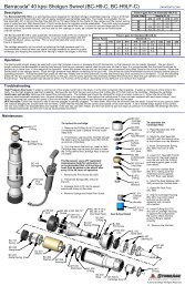
PART NO. 45-200 D170PL (Rev. D)AM SERIES LUBRICATED AIR MOTORSOPERATION & MAINTENANCE MANUALModel 2AM ShownModel 4AM ShownModel 6AM ShownModel 16AM ShownThank you for purchasing this Gast product. It is manufactured to the highest standardsusing quality materials. Please follow all recommended maintenance, operationaland safety instructions and you will receive years of trouble free service.IMPORTANT: PLEASE READ THIS MANUAL AND SAVE FOR FUTURE REFERENCE.General information• Clearances: Model Total End Clearance (in/mm) Top Clearance (in/mm)1AM/1 UP 0.00020/0.0508 0.0015/0.03812AM 0.00025/0.0635 0.0015/0.03812AM * 0.00025/0.0635 0.0025/0.06354AM 0.00035/0.0889 0.0015/0.03814AM * 0.00035/0.0889 0.0025/0.06356AM 0.00035/0.0889 0.0015/0.03818AM 0.00048/0.1219 0.0015/0.038116AM 0.00060/0.1524 0.0015/0.0381* Models with the last three digits greater than 500 (ie 2AM XXX-501)• Vane Life:• Operating Pressure:Depends upon speed, operating pressure and motor maintenance.100 psi or below (7 bar)Product Use Criteria:• Operate at temperature up to 250ºF (121ºC).• Protect unit from dirt and moisture.• Use ONLY compressed air to drive motor.• Air lines connected to motor should be the same size orthe next size larger than the intake port for efficientoutput and speed control.• Protect all surrounding items from exhaust air.• Bearings are grease packed.• Use Gast #AD220 or a detergent SAE#10 automotiveengine oil for lubricating.ISO 9001 & 14001 CERTIFIEDwww.gastmfg.com®Registered Trademark/Trademark of Gast Manufacturing <strong>Inc</strong>., Copyright ©2001 Gast Manufacturing <strong>Inc</strong>. All Rights Reserved.
Your safety and the safety of othersis extremely important.We have provided many important safety messagesin this manual and on your product. Always readand obey all safety messages.This is the safety alert symbol. This symbolalerts you to hazards that can kill or hurt you andothers. The safety alert symbol and the words“DANGER” and “WARNING” will precede all safetymessages. These words mean:You will be killed or seriously injured if you don’tfollow instructions.You can be killed or seriously injured if you don’tfollow instructions.All safety messages will identify the hazard, tell youhow to reduce the chance of injury, and tell youwhat can happen if the safety instructions are notfollowed.INSTALLATIONDANGERWARNINGCorrect installation is your responsibility. Make sureyou have the proper installation conditions and that thespecified installation clearances are available.WARNINGInjury HazardInstall proper guards as needed.Failure to follow this instruction can result inburns or other serious injury.MountingThis product can be installed in any orientation. Mountthe motor to a solid base plate that is mounted to astable, rigid operating surface. Install a pressureregulator or simple shut-off valve to control motor.ConnectionCheck the direction of the motor airflow. A singlerotation motor will operate properly only in one direction.Install a filter in the air line before the connection to themotor. Connect lines to motor in the proper direction.A reversible motor will work equally well in bothdirections. Connecting a 4-way valve with piping toboth air ports of the motor will make reversing possible.Do not add any thrust to the end or side of the shaftwhen making connections. Do not use a hammeron the shaft or connections.AccessoriesAmuffler is shipped with the air motor (except 16AM)but is not installed. Consult your Gast representativefor additional filter recommendations. Install a moisturetrap and filter in the air line ahead of the motor. For themost efficient output and control of speed, use air linesthat are the same size or the next pipe size larger thanthe motor intake port.An automatic air line lubricator should be installed 18”or as close as possible in the air line just ahead of themotor. Adjust the lubricator to feed one drop of oil forevery 50-75 CFM of air moving through the motor. Airconsumption at various speeds and pressures areavailable from your local Gast representative or thefactory.OPERATIONWARNINGInjury HazardAir stream from product may contain solid or liquidmaterial that can result in eye or skin damage.Do Not use combustible gases to drive this motor.Wear hearing protection. Sound level from motormay exceed 85db(A).Failure to follow these instructions can result inburns, eye injury or other serious injury.It is your responsibility to operate this product atrecommended speeds, loads and room ambienttemperatures. Do not run the motor at high speedswith no load. This will result in excessive internalheat that may cause motor damage.The starting torque is less than the running torque. Thestarting torque will vary depending upon the position ofthe vanes when stopped in relation to the air intakeport.Use a pressure regulator and/or simple shut-off valve toregulate the motor’s speed and torque. This will providethe required power and will conserve air.MAINTENANCEWARNINGInjury HazardDisconnect air supply and vent all air lines.Wear eye protection when flushing this product.Air stream from product may contain solid or liquidmaterial that can result in eye or skin damage.Flush this product in a well ventilated area.Do Not use kerosene or other combustible solventsto flush this product.Failure to follow these instructions can result inburns, eye injury or other serious injury.It is your responsibility to regularly inspect andmake necessary repairs to this product in order tomaintain proper operation.
LubricationUse Gast #AD220 or a detergent SAE #10 automotiveengine oil for lubricating. Lubricating is necessary toprevent rust on all moving parts. Excessive moisture inthe air line may cause rust or ice to form in the mufflerwhen air expands as it passes through the motor.Install a moisture separator in the air line and an aftercooler between compressor and air receiver to helpprevent moisture problems.<strong>Manual</strong> LubricationShut the air motor down and oil after every 8 hours ofoperation. Add 10-20 drops of oil to the air motor intakeport.Automatic LubricationAdjust inline oiler to feed 1 drop of oil per minute forhigh speed or continuous duty usage. Do Not overfeedoil or exhaust air may become contaminated.Check intake and exhaust filters after first 500 hours ofoperation. Clean filters and determine how frequentlyfilters should be checked during future operation. Thisone procedure will help assure the product’sperformance and service life.FlushingFlushing this product to remove excessive dirt, foreignparticles, moisture or oil that occurs in the operatingenvironment will help to maintain proper vaneperformance. Flush the motor if it is operating slowly orinefficiently.Use only Gast #AH255B Flushing Solvent. DO NOTuse kerosene or ANY other combustible solvents toflush this product.1. Disconnect air line and muffler.2. Add flushing solvent directly into motor. If usingliquid solvent, pour several tablespoons directlyinto the intake port. If using Gast #AH255B, spraysolvent for 5-10 seconds into intake port.3. Rotate the shaft by hand in both directions for afew minutes.4. You must wear eye protection for this step.Cover exhaust with a cloth and reconnect the airline. Slowly apply pressure until there is no traceof solvent in the exhaust air.5. Listen for changes in the sound of the motor. Ifmotor sounds smooth, you are finished. If motordoes not sound like it is running smoothly,installing a service kit will be required.(See “Service Kit Installation”).Check that all external accessories such as reliefvalves or gauges are attached and are not damagedbefore operating product.ShutdownIt is your responsibility to follow proper shutdownprocedures to prevent product damage.1. Turn off air intake supply.2. Disconnect plumbing.3. Remove air motor from connected machinery.4. Wear eye protection. Keep away from airstream.Use clean, dry air to remove condensation.5. Lubricate motor with a small amount of oil inchamber. Rotate shaft by hand several times.6. Plug or cap each port.7. Coat output shaft with oil or grease.8. Store motor in a dry environment.SERVICE KIT INSTALLATIONGast will NOT guarantee field-rebuilt productperformance. For performance guarantee, theproduct must be returned to a Gast authorizedservice facility.Service kit contents vary. Most contain vanes, end capgasket, body gasket, bearings and a muffler element orfelt.Major and Minor RebuildsTool kits which include a more in-depth rebuildmanual are available through your Gast distributor.These kits include the tools required to remove andreassemble end plates, bearings and shaft seals, and toset the proper end clearance. The rebuild manual alsoincludes step by step instructions, including illustrations,to help achieve a successful rebuild. GastManufacturing, <strong>Inc</strong>. highly recommends using the airmotor rebuild manual and tool kit when attempting aminor or major rebuild to your Gast air motor.Minor Rebuild:1. Remove the end cap.2. Remove dead end plate bolts.3. Remove dead end plate. (Use factory issued tool,do not use screwdriver to remove the end plate.4. Remove the dowel pins from the body and pushback into end plate until flush or just below themachined surface of the end plate.5. Remove vanes.6. Clean parts. Check for scoring on the end plateand rotor assembly. If scoring exists, send unit toa Gast authorized service facility.7. Lubricated models only: Lightly oil and reinstallvanes.8. Place the proper end plate gasket on the endplate. If the original is damaged, replace with anew one supplied in the Service Kit.9. Place the dead end plate on the body.10. Press the bearing onto the shaft using a factorysupplied bearing pusher.11. Tap dowel pins into body and install end platebolts. Tighten bolts to 75-100 in-lbs.12. Set end clearance as required by model:1AM-4AM and NL22-NL52 models - use thebearing taper from kit to lightly tap on inner race ofthe dead end bearing to free up and center therotor in the body.6AM-8AM models - lightly strike the drive endshaft with a soft hammer to push the rotor awayfrom the drive end plate. The rotor must NOT rubon either end plate.13. Reattach end cap.14. If the air motor is lubricated, apply a few dropsof Gast #AD220 lubricant into ports. Rotate shaftby hand for a few rotations.Major Rebuild:1. Remove the end cap.2. Remove dead end plate bolts.
3. Remove dead end plate. (Use factory issued tool,do not use screwdriver to remove the end plate.)4. Remove the dowel pins from the body and pushback into end plate until flush or just below themachined surface of the dead end plate.5. Remove rotor using an arbor press.6. Remove vanes and ejection mechanism ifreversible. (Ejection mechanisms may consist ofvane springs, pins, caps or cam rings.)7. Remove shaft seal and bearings from drive endplate and bearing from dead end plate. (Usefactory issued tool.)8. Do Not remove drive end plate bolts or drive endplate.9. Clean parts. Check for scoring on the end platesand rotor assembly. If scoring exists, send unit toa Gast authorized service facility.10. For reversible models only:1AM and 1UP models - place a new cam ringbetween the rotor and the drive end plate.2AM and 4AM models - place springs and capsin rotor.6AM, 8AM and 16AM models - install push pins.11. Place the drive shaft of the rotor assembly throughthe drive end plate. Press the drive bearing ontothe drive shaft using a factory supplied bearingpusher.12. Using the bearing taper from the Tool Kit, lightlytap on inner race of the drive end bearing to snugup rotor to drive end plate.13. Install new vanes as required by model:All single rotation units - the angle cuts on thevane face to center of the rotor.Reversible units 2AM and 4AM - the notch onvane faces to center of the rotor.6AM, 8AM and 16AM models - install the vanespring lip into the notch at one end of the vaneand place in rotor vane slot with spring facingpushpin.14. Place the proper end plate gasket on the body ofdead end. If the original is damaged, replacewith a new one supplied in the service kit.If your air motor uses O-rings, place the newO-rings in the body groove. Some models do notuse end plate gaskets or O-rings.15. Place the dead end plate on the body.16. Install the dead end bearing and press into placewith bearing pusher tool from tool kit.17. Install the dowel pins.18. Fully tighten the remaining bolts to 75-100 in-lbs.19. Set end clearance as required by model:1AM-4AM and NL22-NL52 models - use thebearing taper from the Tool Kit and lightly tap onthe inner race of the dead end bearing to free upand center the rotor in the body.6AM-8AM models - lightly strike the drive endshaft with a soft hammer to push the rotor awayfrom the drive end plate. The rotor must NOT rubon either end plate.20. Apply a small amount of grease to bearing sealand install the drive end bearing seal by pressingflush with bearing pushing tool from Tool Kit.21. Reattach end cap.22. If the air motor is lubricated, apply a few dropsof Gast #AD220 lubricant into ports and rotateshaft by hand for a few rotations.
EXPLODED PRODUCT VIEWS, PARTS & ORDERING INFORMATIONExploded views are shown forreference only. Units may varydepending upon specific model.4AM SERIESREF# DESCRIPTION QTY 4AM-FRV-13C 4AM-NRV-22B 4AM-FRV-24 4AM-NRV-50C 4AM-NRV-54A 4AM-NRV-70C 4AM-ARV-119 4AM-ARV-120METRIC METRIC1 ∆ SHAFT SEAL 1 AC466B AC466B NAS2 B2328 AA466B B2328 B2328 B23282 ∆ DRIVE END BEARING 1 AA299J AA299J AA299J AB519 AA299J AB519 AB519 AB5192A ∆ DEAD END BEARING 1 AA299J AA299J AA299J AA299J AA299J AA299J AA299J AA299J3 DRIVE END PLATE 1 AC727 AC665 AC727 AG707 AC665` AG707 AK425A AK425A4 ROTOR ASSEMBLY 1 AB617 AB617 AM426 AM455A AM411 AM319A AM455C AM455B5 ∆ VANE 4 AB876 AB876 AB876 AB876 AB8768 AB876 AB876 AB8766 ∆ PUSH PINS 4 AM467 AM467 AM467 AM467 AM4678 AM467 AM467 AM4677 ∆ VANE SPRING 2 AM466 AM466 AM466 AM466 AM4664 AM466 AM466 AM4668 BODY 1 AM425 AM410 AM425 AM410 AM410 AM410 AM410M AM410M9 ∆ ** SHIMS 2 B330 B330 B330 B330 B330 B330 B330 B33010 DEAD END PLATE 1 AC728 AC728 AC727 AC728 AC728 AC728 AB622M AB622M11 ∆ END CAP GASKET 1 AA46 AA46 AA46 AA46 AA46 AA46 AA4612 DEAD END CAP 1 AM307D AM307D AM307D AM307D AM307D AM307D AM307D13 MUFFLER ASSEMBLY 1 AL445 AL445 AL445 AL445 AL445 AL445 AL445 AL44514 ∆ MUFFLER CARTRIDGE 1 AL458 AL458 AL458 AL458 AL458 AL458 AL458 AL45815 ∆ MUFFLER FELT 1 AC983 AC983 AC983 AC983 AC983 AC983 AC983 AC983*** SERVICE KIT 1 K205 K205 K205G K206A K279 K280A K206C K206B4AM SERIESREF# DESCRIPTION QTY 4AM-RV-75*** Item not shown.** #AL484 (9A) O-ring replaces shims on some models.∆ Denotes parts included in the Service Kit.Parts listed are for stock models. For specific OEM models, please consultthe factory. When corresponding or ordering parts, please give completemodel and serial numbers.1 GEAR STD. 1 AA2942 ∆ BEARING 2 AA299J3 PIN 1 AA2974 ROTOR 1 AA2935 ∆ VANE 4 AB8766 ∆ SPRING PIN 4 AM4677 ∆ SPRINGS 2 AM4668 BODY 1 AM4109 ∆ SHIMS 2 B33010 DEAD END PLATE 1 AC72811 ∆ END CAP GASKET 1 AA4612 END CAP 1 AM307D13 DRIVE END PLATE 1 AA42414 SEAL 1 AA466B15 DOWEL PINS 4 AB16216 1/4-28 x .50 PFHMS 6 BB63117 1/4-28 x .625 SHCS 6 BB634*** SERVICE KIT 1 K205
EXPLODED PRODUCT VIEW, PARTS & ORDERING INFORMATIONExploded views are shown forreference only. Units may varydepending upon specific model.6AM SERIESREF# DESCRIPTION QTY 6AM-FRV-5A 6AM-NRV-7A 6AM-NRV-22A 6AM-FRV-23A 6AM-ARV-54 6AM-ARV-55 6AM-NRV-11ANEMA1 DRIVE END CAP 1 AD642A AD642A AD642A AD642A AC988 AC988 AD642A2 ∆ SHAFT SEAL 1 AC849 AC849 AC849 AC849 AK423 AK423 AC8493 ∆ O-RING 1 AD649 AD649 AD649 AD649 AC989 AC989 AD6494 ∆ DRIVE END BEARING 1 AD638A AD638A AD638A AD638A AC894B AC894B AD638A5 DOWEL PIN 4 AB162 AB162 AB162C AB162 AB162C AB162C AB162C6 DRIVE END PLATE 1 AD651 AD666 AD667 AD651 AK424 AK424 AD6677 ∆ BODY GASKET 2 AD641 AD641 AD641 AD641 AD641 AD641 AD6418 BODY 1 AD650A AD665 AD665 AD650A AD665D AD665D AD6659 KEY 1 AB136 AB136 AB136 AB136 AK422 AK422 AB13610 ROTOR ASSEMBLY 1 AD652 AD652 AC398 AC779 AD648E AD648D AD64811 ∆ PUSH PIN 2 AD655A AD655A AD655A AD655A4 AD655A AD655A AD655A12 ∆ VANE SPRING 4 AD692 AD692 AD692 AD6928 AD692 AD692 AD69213 ∆ VANE 4 AD691 AD691 AD691 AD6918 AD691 AD691 AD69114 DEAD END PLATE 1 AD651 AD651 AD651 AD651 AD651 AD651 AD65115 ∆ DEAD END BEARING 1 AB519 AB519 AB519 AB519 AB519 AB519 AB51916 ∆ END CAP GASKET 1 AD644 AD644 AD644 AD644 AD644 AD644 AD64417 DEAD END CAP 1 AD643 AD643 AD643 AD643 AD643 AD643 AD643*** MUFFLER ASSEMBLY 1 AC990 AC990 AC990 AC990 AC990 AC990 AC990*** MUFFLER FELT 1 AC993 AC993 AC993 AC993 AC993 AC993 AC993*** SERVICE KIT 1 K208 K208 K281 K281 K281A K281B K208*** Item not shown.∆ Denotes parts included in the Service Kit.Parts listed are for stock models. For specific OEM models, please consult the factory.When corresponding or ordering parts, please give complete model and serial numbers.
WARRANTYGast finished products, when properly installed and operated under normal conditions of use, are warranted by Gast tobe free from defects in material and workmanship for a period of twelve (12) months from the date of purchase fromGast or an authorized Gast Representative or Distributor. In order to obtain performance under this warranty, the buyermust promptly (in no event later than thirty (30) days after discovery of the defect) give written notice of the defect toGast Manufacturing <strong>Inc</strong>orporated, PO Box 97, Benton Harbor Michigan USA 49023-0097 or an authorized ServiceCenter (unless specifically agreed upon in writing signed by both parties or specified in writing as part of a Gast OEMQuotation). Buyer is responsible for freight charges both to and from Gast in all cases.This warranty does not apply to electric motors, electrical controls, and gasoline engines not supplied by Gast. Gast’swarranties also do not extend to any goods or parts which have been subjected to misuse, lack of maintenance,neglect, damage by accident or transit damage.THIS EXPRESS WARRANTY EXCLUDES ALL OTHER WARRANTIES OR REPRESENTATIONS EXPRESSED ORIMPLIED BY ANY LITERATURE, DATA, OR PERSON. GAST’S MAXIMUM LIABILITY UNDER THIS EXCLUSIVEREMEDY SHALL NEVER EXCEED THE COST OF THE SUBJECT PRODUCT AND GAST RESERVES THE RIGHT,AT ITS SOLE DISCRETION, TO REFUND THE PURCHASE PRICE IN LIEU OF REPAIR OR REPLACEMENT.GAST WILL NOT BE RESPONSIBLE OR LIABLE FOR INDIRECT OR CONSEQUENTIAL DAMAGES OF ANY KIND,however arising, including but not limited to those for use of any products, loss of time, inconvenience, lost profit, laborcharges, or other incidental or consequential damages with respect to persons, business, or property, whether as aresult of breach of warranty, negligence or otherwise. Notwithstanding any other provision of this warranty, BUYER’SREMEDY AGAINST GAST FOR GOODS SUPPLIED OR FOR NON-DELIVERED GOODS OR FAILURE TO FURNISHGOODS, WHETHER OR NOT BASED ON NEGLIGENCE, STRICT LIABILITY OR BREACH OF EXPRESS ORIMPLIED WARRANTY IS LIMITED SOLELY, AT GAST’S OPTION, TO REPLACEMENT OF OR CURE OF SUCHNONCONFORMING OR NON-DELIVERED GOODS OR RETURN OF THE PURCHASE PRICE FOR SUCH GOODSAND IN NO EVENT SHALL EXCEED THE PRICE OR CHARGE FOR SUCH GOODS. GAST EXPRESSLYDISCLAIMS ANY WARRANTY OF MERCHANTABILITY OR FITNESS FOR A PARTICULAR USE OR PURPOSE WITHRESPECT TO THE GOODS SOLD. THERE ARE NO WARRANTIES WHICH EXTEND BEYOND THE DESCRIPTIONSSET FORTH IN THIS WARRANTY, notwithstanding any knowledge of Gast regarding the use or uses intended to bemade of goods, proposed changes or additions to goods, or any assistance or suggestions that may have been madeby Gast personnel.Unauthorized extensions of warranties by the customer shall remain the customer’s responsibility.CUSTOMER IS RESPONSIBLE FOR DETERMINING THE SUITABILITY OF GAST PRODUCTS FOR CUSTOMER’SUSE OR RESALE, OR FOR INCORPORATING THEM INTO OBJECTS OR APPLICATIONS WHICH CUSTOMERDESIGNS, ASSEMBLES, CONSTRUCTS OR MANUFACTURES.This warranty can be modified only by authorized Gast personnel by signing a specific, written description of anymodifications.MAINTENANCE RECORDDATEPROCEDURE PERFORMED
PART NO. 45-200 D170PL (Rev. D)TROUBLESHOOTING CHARTProblemLow Low Won’t Run Runs Hot Runs Well Reason & RemedyTorque Speed Then Slows For Problem.Down● ● ● Dirt or foreign material present.Inspect and clean.● ● ● Internal rust. Inspect and clean.● ● ● ● ● Vanes misaligned. Realign vanes.● ● Low air pressure. <strong>Inc</strong>rease pressure.●Air line too small. Install larger line(s).● ● Restricted exhaust. Inspect and repair.● ● ● ● Motor is jammed. Disassemble and repair.● ● Air source inadequate. Inspect and repair.● ● Air source too far from motor.Reconfigure setup.AUTHORIZED SERVICE FACILITIESGast Manufacturing <strong>Inc</strong>. Gast Manufacturing <strong>Inc</strong>. Brenner Fiedler & Assoc. Gast Manufacturing Co., Ltd2550 Meadowbrook Road 505 Washington Ave 13824 Bentley Place Beech House, Knaves BeechBenton Harbor, MI 49022 Carlstadt, NJ 07072 Cerritos, CA 90701 Business Centre, LoudwaterTEL: 616-926-6171 TEL: 201-933-8484 TEL: 800-843-5558 High Wycombe, Bucks HP 10 9SDFAX: 616-927-0808 FAX: 201-933-5545 TEL: 310-404-2721 Englandwww.gastmfg.com FAX: 310-404-7975 TEL: 44 628 532600FAX: 44 628 532470Wainbee Limited Wainbee Limited Japan Machinery Co., Ltd. General Correspondence215 Brunswick Blvd. 5789 Coopers Avenue Central PO Box 1451 should be sent to:Pointe Claire, Quebec Mississauga, Ontario Tokyo, 100-91 Japan Gast Mfg. <strong>Inc</strong>./A Unit of IDEX CorporationCanada H9R 4R7 Canada L4Z 3S6 TEL: 81-3-3573-5421 P O Box 97TEL: 514-697-8810 TEL: 905-568-1700 FAX: 81-3-3571-7865 Benton Harbor, MI 49023-0097FAX: 514-697-3070 FAX: 905-568-0083 or: 81-3-3571-7896ISO 9001 & 14001 CERTIFIEDwww.gastmfg.com
OMMTechnical InformationTechnical dataTECHNICAL DATA FOR OMM WITH 16 MM AND 5/8 IN CYLINDRICAL SHAFTType OMM OMM OMM OMM OMM OMMMotor size 8 12.5 20 32 40 50Geometric displacement cm3 8.2 12.9 19.9 31.6 39.8 50.3[in 3 ] [0.50] [0.79] [1.22] [1.93] [2.43] [3.08]Max. speedMax. torqueMax. outputMax. pressure dropMax. oil flowmin -1 cont. 1950 1550 1000 630 500 400[rpm] int. 1) 2450 1940 1250 800 630 500cont.11 16 25 40 45 46[95] [140] [220] [350] [400] [410]Nm15 23 35 57 70 88[lbf-in]int. 1) [135] [200] [310] [500] [620] [780]peak 2) 21 33 51 64 82 100[185] [290] [450] [570] [725] [890]1.8 2.4 2.4 2.4 2.2 1.8cont.kW [2.4] [3.2] [3.2] [3.2] [3.0] [2.4][hp]int. 1) 2.6 3.2 3.2 3.2 3.2 3.2[3.5] [4.3] [4.3] [4.3] [4.3] [4.3]cont.100 100 100 100 90 70[1450] [1450] [1450] [1450] [1310] [1020]bar140 140 140 140 140 140[psi]int. 1) [2030] [2030] [2030] [2030] [2030] [2030]peak 2) 200 200 200 160 160 160[2900] [2900] [2900] [2320] [2320] [2320]16 20 20 20 20 20cont.l/min [4.2] [5.3] [5.3] [5.3] [5.3] [5.3][gpm]int. 1) 20[5.3]25[6.6]25[6.6]25[6.6]25[6.6]25[6.6]Max. starting pressure bar 4 4 4 4 4 4with unloaded shaft [psi] [60] [60] [60] [60] [60] [60]at max. press. drop cont. 7 12 21 34 38 41Min. starting Nm [lbf·in] [60] [105] [185] [300] [335] [365]torque at max. press. drop int. 1) 10 17 29 48 62 79Nm [lbf·in] [90] [150] [255] [425] [550] [700]min -1Min. speed 3] [rpm]50 40 30 30 30 30TypeMax. inlet pressureOMM 8 - 501)Intermittent operation: the permissible values may occur for max. 10% of every minute.2)Peak load: the permissible values may occur for max. 1% of every minute.3)Operation by lower speeds may be slightly less smooth.bar140cont.[psi] [20309bar175[psi]int. 1) [25409bar225[psi]peak 2) [3260]20 DKMH.PK.170.C4.02 520L0346
OMMTechnical InformationDimensions – US versionDIMENSIONSOMM.End port version.Type L max.L 1mm[in]OMM 8OMM 12.5OMM 20OMM 32OMM 50104.0 3.5[4.09] [0.14]106.0 5.5[4.17] [0.22]109.0 8.5[4.29] [0.33]114.0 13.5[4.49] [0.53]122.0 21.5[4.80] [0.85]C: 1 / 4 - 28 UNF - 2B;min. 10 mm [0.39 in] deepD: 9 ⁄16 - 18 UNF ;12 mm [0.47 in] deepO-ring boss portE: 3 ⁄8 - 24 UNF ;8 mm [0.39 in] deepO-ring port30 DKMH.PK.170.C4.02 520L0346
OML and OMMTechnical InformationHydraulic SystemsINSTALLATION OF THESAUER-DANFOSSORBITAL MOTORSAbout the design• To ensure efficient operation all hydraulic components must be installed according totheir individual instructions.• The pump line must include a manometer connection.• To ensure designed contact and minimise the tension all mounting flanges must beflate.Hydraulic lines must be fitted correctly to prevent air entrappment.About the assembly• Follow the mounting instructions printed on the inside of the cardboard box.• To prevent contamination, do not dismantle the plastic plugs from the connectionports untill the fittings are ready to be assempled.• Check that there is full face contact between the motor mounting flange and themating part.• Do not force the motor into place when tightening the mounting screws.• Avoid unsuitable sealing material on fittings such as pack twine, teflon and others.Use only bonded seals, O-rings, steel washers and the like.• When tightening the fittings never use a torque higher than the max. tighteningtorque stated in the instructions.• Make sure that the cleanliness of the oil used is better than 20/16 (ISO 4406). Alwaysuse a filter for oil refilling.STARTING UP ANDRUNNING IN THEHYDRAULIC SYSTEM• Through a small-meshed filter fill up the tank with oil to the upper oil level mark .• Start the drive engine, and if possible, let it work at its lowest speed. If the motor isprovided with bleed screws, keep these open until the emerging oil is non-foaming.• Check that all components are correctly connected (pump following the rightdirection of rotation etc.).• In load-sensing systems, also make sure that the signal lines are bled.• Indications of air in the hydraulic system:- oam in the tank- jerky movements of motor and cylinder- noise• If so required, refill with oil.• Connect the system to a separate tank that includes a filter (fineness max. 10 µm) withtwice the capacity of the max. oil flow. Let the entire system run without load (nopressure) for about 30 minutes.• Do not load the system until it is all bled and clean.• Check the tightness of the system and make sure that its performance is satisfactory.• Change the oil filter, and if so required, refill with oil.OPERATION• Do not expose the motor to pressures, pressure drops and speeds above the max.values stated in the catalogue.• Filter the oil to ensure that the contamination level 20/16 (ISO 4406) or better.MAINTENANCE• When working with hydraulic systems, the main criteria of operating safety andendurance is careful maintenance• Always renew and replace oil, oil filters and air filters according to the instructionsgiven by the respective manufacturers• Regularly check the condition of the oil• Frequently check system tightness and oil levelDKMH.PK.170.C4.02 520L034635
CORPORATION®I N S TA L L ATION ANDMAINTENANCE SHEETDial-Air Regulator Model R21Bwith Variations and AccessoriesCAUTIONE X C E P T as otherwise specified by the manufacturer, this product is specifically designed for compressedair service, and use with any other fluid (liquid or gas) is a misapplication. For example, use withor injection of certain hazardous liquids or gases in the system (such as alcohol or liquid petroleum gas)could be harmful to the unit or result in a combustible condition or hazardous external leakage.Manufacturer's warranties are void in the event of misapplication, and manufacturer assumes no responsibilityfor any resulting loss. Before using with fluids other than air for nonindustrial applications or for lifesupport systems, consult manufacturer for approval.INSTALLATION1. Refer to caution above.2. Maximum inlet pressure is 300 psig (20,7 bar). Maximum operating airand ambient temperature is 175° (79,4°C).3. Install as close as possible to where regulated air is needed.4. Install the unit with the air flowing through the body in the directionindicated by the arrow.5. Install the same pipe size as the pipe line in use. Avoid using fittings,couplings, etc., that restrict the airflow, unless maximum flow is notneeded.6. Regulator may be installed in any position. (See page 2 for detailson how to adjust regulator.)7. A pressure gauge is not required; however, a gauge may be attachedto one of the 1 / 4 " NPT female cross ports. These ports may also beused as regulated outlets; otherwise, plug both cross ports.8. Panel mounting requires a 2 11 /16" (69 mm) diameter hole. Units maybe mounted on panel up to 1 1 /4" (32 mm) thick. Before mounting theunit, remove the adjustment knob. Replace adjustment knob after regulatoris mounted.MAINTENANCE1. Occasionally remove bottom plug and clean plug, body valve seat andmain valve. Relubricate U-cup seal with Magnalube-G® whenever regulatoris cleaned. (See page 2 for lubrication instructions.)2. TO DISASSEMBLE: Shut off air to regulator and vent air line on bothsides of regulator. Remove lock knob, adjustment knob, and retainingring. Leave dial screw in position. It is not necessary to remove thisscrew to service unit. Lift bonnet assembly out of the body and removepistons, support washer, and Belleville springs. Remove the bottomplug and pull out the main valve and pilot valve. (See items 4 and 5below.)3. TO ASSEMBLE: Relubricate all seals and sealing surfaces withM a g n a l u b e - G ® . Assemble main valve, pilot valve spring, pilot valve,main valve spring, and bottom plug. Lay bottom piston, with flat surfacedown, on assembly table. Slip upper piston assembly on bottompiston. Add support washer and two Belleville springs with insidediameters contacting. Place spring and needle/o-ring assembly intotop of upper piston. Place bonnet assembly on assembled pistons andpress down firmly. Place o-ring** in body. Place assembled bonnetand pistons in body and install retaining ring.CAUTION: ENSURE RETAINING RING IS FULLY LOCKED INTORETAINING GROOVE IN BODY.Install the adjustment knob and then the lock knob.4. IF UNIT WILL NOT REGULATE TO PRESSURE NEEDED, OF IFPRESSURE DROP BECOMES EXCESSIVE: Remove bottom plug,main valve, and pilot valve. Clean and check seals and valve seats forwear or damage. Relubricate seals with Magnalube-G ® .5. IF UNIT LEAKS UNDER ADJUSTMENT KNOB: The cause may bedirty or worn main valve seat. Install Repair Kit No. RRP-95-151. Asmall, constant bleed of up to 5 scfh is normal.Install Belleville springs like this...LOCK KNOBNNRRETAININGRINGDIAL DISKDIAL SCREWNEEDLEBELLEVILLESPRINGSUPPERPISTONO-RINGBOTTOMPISTONPIPE PLUG(2 Required)SPRINGPILOTVALVESPRINGU-CUP SEALO-RINGLOCK FASTENERADJUSTMENTKNOB NNRTAMPER RESISTANTKIT (Optional)WASHERO-RINGDIAL FACEBONNETASSEMBLYO-RING**SUPPORTWASHERO-RINGUPPER PISTONCUPO-RINGO-RINGBODYNNRMAIN VALVEASSEMBLYMAIN VALVESPRINGBOTTOM PLUGNNRNNR=NOT NORMALLY REPLACED 83-289-000-FL 8/99Printed in U.S.A.
LUBRICATION OF DIAL-AIR REGULATORSNOTE: NEVER TAMPER WITHADJUSTING SCREWThe factory packs all moving seals with a heavy lubricating grease. Undernormal conditions this will last through millions of cycles. However, underconditions of wet air, unusual high flows, or light oil from a lubricator somewherein the circuit moisture can get into the Dial-Air regulator and theoriginal lubrication can be washed out.O-RINGO-RINGO-RINGO-RINGO-RINGO-RINGU-CUPProper lubrication in our Dial-Air series regulators is absolutely essential.Symptoms of a dry regulator:1. Excessive leaking through the relief vent.2. Loss of calibration.3. Regulator cannot attain high secondary pressures.4. Erratic secondary pressures.Remedy:Disassemble regulator and lubricate indicated seals with Magnalube-G ® .302021OFF11bar1010 160psi140150302010SETTING PRESSURE STOPS1 2 3 1 / 8 "4 5TAB STOP8090100809010080 90100OUTER KEY701107011070110657666077F O R12060 560 58120488120A D J U S T M E N T50504504130130130K N O B394040 3940 39K E Y - W A YTAB SET FOR A MAXIMUMPRESSURE STOP21OFF11bar10psi160140150TAB SET FOR A MINIMUMPRESSURE STOPP L A S T I CC O U P L I N GTAMPER-PROOF LOCKEDSETTING1. To set adjustment to a maximum pressure stop, an adjustment tab is provided so that regulator adjustment cannot be turned past apreset maximum pressure. To preset this tab, remove the clear plastic knob by first taking off the white plastic lock knob. Loosen dial screw androtate tab stop to the desired pressure limit. Set groove of the white plastic coupling anywhere between zero and the tab stop. Line up theinner key on the clear plastic adjustment knob with the groove and drop in place. Outer key on the adjustment knob must now be to theleft of the tab stop.2. To set adjustment to a minimum pressure stop, repeat the process above, but set the groove of the white plastic coupling anywherebetween the pressure desired and the maximum pressure number, 160. When the adjustment knob is replaced, its outer key shouldnow be to the right of the tab stop. Adjustment can now only be made between tab and maximum pressure.3. Adjustment can be fixed at a set pressure by purchasing Tamper-Proof Kit No. RRP-95-585. This is just an additional tab stop ring.Remove the dial screw and the white dial face, place the additional ring on top of the original ring and replace the white dial face and dialscrew. Set one of the tab stops on one side of the pressure desired; set the other to the opposite side of the pressure figure, as shown.Leave approximately 1/8" between the stops, and tighten dial screw. Set the groove of white plastic coupling in line with desired pressure number,and replace adjustment knob so that key on inside of the outer edge of the clear plastic knob is located between the two tabs. Replacelock knob. The locked adjustment is now also tamper proof because the operator would have to remove both knobs to change it.4. To locate tabs so that adjustment can be made only between a predetermined minimum and maximum, follow the same procedureabove, except spread the tabs further apart, to the minimum pressures desired, and locate outer key of adjustment knob between thetwo tabs.WARNING: If dial screw and washer have been removed, do not rotate keyway of plastic coupling through the “off” position on the scale of the dialface. This can offset the calibration so that the reading on the dial would not match a pressure gauge.30202111bar1010 160OFFpsi140150TABS SET FOR A MINIMUM ANDMAXIMUM PRESSURE STOPINNER KEYF O RA T T A C H I N GTO PLASTICC O U P L I N GVIEW OF UNDERSIDE OFTHE ADJUSTMENT KNOBP O I N T E RREPAIR KITS AND REPLACEMENT PARTSRepair Kit - Relieving .................................................................RRP-95-151Repair Kit - Bottom Piston and Seal...........................................RRP-95-192Standard-Pressure Gauge (0-160) ............................................GRP-95-229Low-Pressure Gauge (0-60 psi) .................................................GRP-95-230O-Ring Kit ..................................................................................GRP-95-260Standard-Pressure, Belleville-Spring Washer ............................RRP-95-905Low-Pressure, Belleview-Spring Washer...................................RRP-95-906Pilot Valve and Pilot Spring........................................................RRP-95-934Series A Conversion Kit .............................................................RRP-95-766Series B Conversion Kit-Nitrile ...................................................RRP-95-914Series C Conversion Kit-Fluoro..................................................RRP-95-915ACCESSORIESWall Mounting Bracket (1/4" BSP) .............................................RPA-95-092Tamper-Resistant Kit .................................................................RRP-95-585Wall Mounting Bracket ...............................................................RRP-95-5902