AFFIXUS® Hip Fracture Nail Surgical Technique - Biomet
AFFIXUS® Hip Fracture Nail Surgical Technique - Biomet
AFFIXUS® Hip Fracture Nail Surgical Technique - Biomet

Create successful ePaper yourself
Turn your PDF publications into a flip-book with our unique Google optimized e-Paper software.
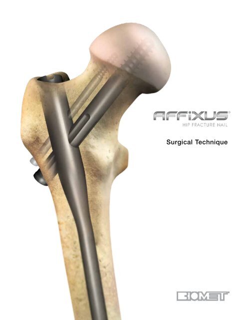
<strong>Surgical</strong> <strong>Technique</strong>
One Surgeon. One Patient. ®Over 1 million times per year, <strong>Biomet</strong> helps one surgeonprovide personalized care to one patient.The science and art of medical care is to provide the rightsolution for each individual patient. This requires clinicalmastery, a human connection between the surgeon and thepatient, and the right tools for each situation.At <strong>Biomet</strong>, we strive to view our work through the eyes ofone surgeon and one patient. We treat every solution weprovide as if it’s meant for a family member.Our approach to innovation creates real solutions that assisteach surgeon in the delivery of durable personalized careto each patient, whether that solution requires a minimallyinvasive surgical technique, advanced biomaterials or apatient-matched implant.When one surgeon connects with one patient to providepersonalized care, the promise of medicine is fulfilled.
AFFIXUS ® <strong>Hip</strong> <strong>Fracture</strong> <strong>Nail</strong>ContentsFeatures and Benefits................................................................................................................................................... 3Indications and Pre-op Planning................................................................................................................................... 7Patient Positioning and Reduction................................................................................................................................ 8Entry and Canal Preparation......................................................................................................................................... 9<strong>Nail</strong> Insertion............................................................................................................................................................... 12Proximal Locking......................................................................................................................................................... 15Distal Locking.............................................................................................................................................................. 23End Cap Placement.................................................................................................................................................... 25Implant Removal......................................................................................................................................................... 26Implant Diagrams........................................................................................................................................................ 27Product Ordering Information..................................................................................................................................... 28US Surgeon Design TeamGeorge J. Haidukewych, MDOrlando, FLDaniel S. Horwitz, MDSalt Lake City, UTFrank A. Liporace, MDNewark, NJS. Andrew Sems, MDRochester, MNInternational SurgeonDesignerPeter Giannoudis, MDLeeds, UK1
AFFIXUS ® <strong>Hip</strong> <strong>Fracture</strong> <strong>Nail</strong>Strength and Stability in the Proximal Femur• Optimal lag screw design for resistance to cut-out• Easy-to-use instrumentation and targeting jig, whichincludes Goal Post technology, aids in lag screwplacement• Extensive range of neck/shaft angles, distal diameters,and nail lengths – combined with a small proximalnail diameter – allows the surgeon to achieve a closematch for each patient’s anatomy• Unique distal bend facilitates entry through theproximal 1/3 of the femur and reduces potential foranterior cortex penetration3
AFFIXUS ® <strong>Hip</strong> <strong>Fracture</strong> <strong>Nail</strong>A system of choices for effective treatmentof proximal femoral fractures• Short (180 mm) and long (260 - 460 mm) nail optionstreat a wide range of proximal fracture indicationsusing a single set of user-friendly instruments• 15.6 mm proximal nail diameter• Proximal 4˚ lateral bend allows for greatertrochanteric entry site• 125˚ and 130˚ neck angles provide a range ofanatomical options• 10˚ of proximal anteversion built into the nails• 10.5 mm diameter cannulated lag screw for bonepreservation• Unique thread spacing and design of the lag screwhelps to resist displacement and cut-out• 3° distal bend facilitates ease of insertion through theproximal intertrochanteric/subtrochanteric region• Pre-loaded set screw for ease of use• 5.0 mm anti-rotation (AR) screw for rotationalcontrol (optional)• Shouldered lag screw and AR screw help preventmedial screw disengagement• Long nail maintains a 1.8 m radius of curvature toclosely match the femoral anatomy• 5.0 mm diameter distal interlocking screws have alarge core diameter for strong fixation• Static or dynamic distal locking options with a6 mm dynamization range• Chamfer on the front distal tip helps facilitateinsertion and minimizes risk of stress on theanterior cortex in the distal femur4
Multiple locking options for optimal implant stabilityThe AFFIXUS ® <strong>Hip</strong> <strong>Fracture</strong> <strong>Nail</strong> System, comprised of short and long nails, provides surgeons withan intramedullary hip screw to stabilize fractures of the proximal femur. The AFFIXUS ® <strong>Hip</strong> <strong>Fracture</strong><strong>Nail</strong> combines the principles of a compression hip screw with the biomechanical advantages of anintramedullary nail.5
AFFIXUS ® <strong>Hip</strong> <strong>Fracture</strong> <strong>Nail</strong>Figure 166
AFFIXUS ® <strong>Hip</strong> <strong>Fracture</strong> <strong>Nail</strong>AFFIXUS ® <strong>Hip</strong> <strong>Fracture</strong> <strong>Nail</strong>Short – (180 mm)AFFIXUS ® <strong>Hip</strong> <strong>Fracture</strong> <strong>Nail</strong>Long – (260 - 460 mm)Indications and Pre-op PlanningThe AFFIXUS ®<strong>Hip</strong> <strong>Fracture</strong> <strong>Nail</strong> System* is designedfor antegrade trochanteric insertion to treat the followingfractures (Figure 1):The AFFIXUS ®<strong>Hip</strong> <strong>Fracture</strong> <strong>Nail</strong> System is intendedto treat stable and unstable proximal fractures of thefemur including pertrochanteric fractures, intertrochantericfractures, high subtrochanteric fractures and combinationsof these fractures, including non-union, malunion andtumor resections. The Long <strong>Nail</strong> system is additionallyindicated to treat pertrochanteric fractures associatedwith shaft fractures, pathologic fractures in osteoporoticbone (including prophylactic use) of the trochanteric anddiaphyseal areas, impending pathological fractures, longsubtrochanteric fractures, ipsilateral femoral fractures,proximal or distal non-unions, malunions, revisionprocedures and tumor resections.Note: Bone screws referenced in this material arenot intended for screw attachment or fixation tothe posterior elements (pedicles) of the cervicalthoracic or lumbar spine.* System includes short (180 mm) and long (260-460 mm) nails,in 20 mm increments.7
AFFIXUS ® <strong>Hip</strong> <strong>Fracture</strong> <strong>Nail</strong>Figure 2Patient Positioning and ReductionPlace the patient in the supine or lateral position ona fracture table or radiolucent imaging table. Lateralaccess to the proximal femur is required. Intraoperativeimage intensification with a C-arm is required to obtainAP and lateral imaging of the operative area duringpreoperative preparation (reduction) and throughout theprocedure for nail insertion, nail locking, and anteversionalignment. Avoid excessive abduction of the hipduring reduction as the access to the starting pointand nail insertion may be impeded. The trunk maybe laterally flexed away from the operative side to improveaccess to the starting point. The contralateral leg maybe flexed at the hip or scissored below the affected legin the supine position (Figure 2).Closed <strong>Fracture</strong> ReductionFluoroscopy must be used to verify proper fracturereduction.• Acceptable fracture alignment must be obtained priorto implant insertion• Surgeon must avoid varus malreductions• Use a combination of traction, rotation, adduction, andflexion/extension of the leg to obtain an acceptablereduction• Open reductions may be required for morecomplicated fracture patterns and should beused when an acceptable closed reductioncannot be obtained (see page 10)Initial IncisionMake an incision proximal to the tip of the greatertrochanter in line with the femoral axis. Divide the fascialata in line with its fibers and access the tip of the greatertrochanter.8
Trochanteric entry pointFigure 3Entry reamer shapematches proximal nailshapeAwlFigure 4Entry and Canal PreparationFemoral Entry PreparationAttach the standard 3.2 mm guide pin to thepistol guidewire gripper (2810-01-001) or power sourceand pass it through the tip of the greater trochanter intothe center of the femoral canal. Position the entry on thetip of the greater trochanter (Figure 3). Confirm on AP andlateral fluoroscopy views that the entry pin is centeredon the trochanter.Option 1:Figure 5 Figure 6Cannulated Entry Reamer (One-step 16.6 mm) Attach thecannulated entry reamer (2112-01-102 or 2112-01-103)to the power source and pass it over the guide pin throughthe entry portal (Figure 4).It is essential to ream until the reamer’s proximal shaftpasses with the greater trochanter’s cortical bone as theshape of the entry reamer matches the nail shape and thetop of the cylindrical segment of the reamer correspondsto the top of the nail (Figure 4). Reaming should continueuntil the tip of the entry reamer is at the level of the lessertrochanter and not beyond.Option 2: Cannulated AwlPass the cannulated awl over the guide pin and introducewith a rotation motion until the awl is buried to at least halfits blade length (Figure 5 & 6).9
AFFIXUS ® <strong>Hip</strong> <strong>Fracture</strong> <strong>Nail</strong>Figure 7 Figure 8Open <strong>Fracture</strong> ReductionOnce access to the femoral canal has been gained, placethe ball nose guide wire into the entry site utilizing thepistol guide wire gripper (2810-01-001) (Figure 7).Obtain appropriate anatomic reduction in order to restorelength, anatomic axis alignment, and rotation of theinjured limb. Reduction can be achieved through thesurgeon’s preferred method such as traction, externalfixator, external aids, or joysticks. To aid in manipulatingthe fracture fragments and passing the ball nose guidewire, long (7.5 mm diameter, 2810-01-007) and short(6.5 mm diameter, 2810-01-008) reduction tools areavailable.Insert the reduction tool into the medullary canal, pastthe fracture site. Once the fracture is in alignment,pass the ball nose guide wire, available in both 80 cm(2810-01-080) and 100 cm (2810-01-100) lengths, acrossthe fracture site. Remove the reduction tool (Figure 8).10
Figure 9Figure 10Canal PreparationShort <strong>Nail</strong>Confirm that the femoral diaphysis is wide enough andlong enough to allow the selected nail diameter to pass.Ream as necessary to enlarge the diaphysis to accept theselected nail.Long <strong>Nail</strong>Achieve proper alignment of the injured limb prior toreaming. Maintain alignment throughout the reamingprocess to avoid eccentric reaming. Commence reamingby placing the flexible reamer over the ball nose guide wire(Figure 9).Ream the medullary canal in millimeter increments untilcortical bone is reached and in half-millimeter incrementsthereafter. Surgeon preference should dictate the actualextent of intramedullary reaming. Monitor the reamingprocedure using image intensification to avoid eccentric orexcessive cortical reaming.Note: It is recommended to over-ream the diaphysis by 2 mm.<strong>Nail</strong> Length SelectionWith the tip of the ball nose guide wire at the level ofthe desired depth of nail insertion, slide or snap the naildepth gauge (Cat. No. 2112-01-106) onto the ball noseguide wire until it contacts the bone, ensuring that thetip does not fall into the existing trochanteric entry canal,thus providing an inaccurate measurement. To obtain theappropriate nail length, read the measurement mark on thenail depth gauge that is closest to the beginningof the black transition area on the guide wire (Figure 10). Ifa nail of the exact measured length is not available, choosea shorter nail of the next closest available length. A directmeasurement can also be taken of the uninjured extremityusing either radiographs with magnification markers,or directly on the uninjured limb.11
AFFIXUS ® <strong>Hip</strong> <strong>Fracture</strong> <strong>Nail</strong>Alignment of proximaltargetingFigure 11 Figure 12<strong>Nail</strong> InsertionJig AssemblySelect the appropriate targeting jig that corresponds to theneck shaft angle of the implant selected. Insert the jig boltthrough the targeting jig using the jig bolt driver(Cat. No. 2810-13-037 or 2810-13-006) (Figure 11).Note: 130º neck angle is most commonly used(Figure 12).12
Jig Tab<strong>Nail</strong> SlotAlignment of distaltargetingFigure 13AFigure 13BWhen assembling the nail to the insertion jig, ensure that thejig tabs align with the slots on the nail so that the nail fully seatsin the targeting jig (Figure 13A). Once the nail is fully seated,securely tighten the jig bolt using the jig bolt driver(2810-13-037 or 2810-13-006).Note: If it is difficult to attach the nail to the jig, doublecheckthat the nail and jig are identified with the sameangle. The nail will only align with the jig if they have thesame neck-shaft angle.Check the assembly prior to nail introduction. Pass thelag screw sheath through the targeting jig. A properlyassembled nail and jig will allow the lag screw drill to bedirected through the sleeve and through the center of thelag screw hole in the nail.When using a short (180 mm) nail, confirm the targetingalignment of the distal interlocking screws using the greensheaths and drill bits in the same manner (Figure 13B).13
AFFIXUS ® <strong>Hip</strong> <strong>Fracture</strong> <strong>Nail</strong>Figure 14 Figure 15<strong>Nail</strong> InsertionInsert the nail by hand over the 3 mm ball nose guide wireinto the medullary canal. Take care not to strike the jig ortargeting arm with the mallet. A curved impaction tool (Cat.No. 2112-01-204) is included in the set and is meant tobe used for gentle taps of the mallet to fine tune the finalseating of the nail.Note: The insertion jig should not be hammered on.It may be helpful to preliminarily insert the trochanteric nailutilizing its bow to facilitate clearance of the medial femoralcortex of the proximal fragment. To do this, rotate theinsertion jig anteriorly (toward the ceiling). In this positionthe distal bend in the nail will be angled laterally to aid inpassing the nail through the greater trochanteric entry site,and avoid medial cortical penetration.As the nail passes the medial cortex of the proximalfragment, slowly derotate the jig handle into the usuallateral position, so that the anterior bow of the nail nowcorresponds with the anterior bow of the femur (Figure 14).If the nail requires substantial force to advance, remove itand ream an additional millimeter. Avoid excessive forcewhen inserting the nail. Advance the nail until the lag screwaligns to the desired position into the femoral head andneck to allow ideal placement of the lag screw (Figure 15).Maintenance of reduction must be confirmed prior to lagscrew insertion. If the reduction has shifted to a suboptimalposition, further hip adduction, traction, and rotationaladjustments can be made prior to lag screw placement.Remove the ball nose guide wire.14
Lag Screw SheathLag Screw3.2 mm sleeveLag ScrewTrocharFigure 16AFigure 16BProximal LockingLag Screw Guide Pin IntroductionInsert the lag screw sheath assembly (lag screwsheath—2112-01-300, lag screw trochar—2112-01-301,lag screw 3.2 mm sleeve—2112-01-302) through thelag screw hole in the jig. Pass the trochar through thesheath and make an appropriate skin incision wherethe trochar contacts the skin. Advance the trocharthrough the tissue until the tip is seated against thelateral femoral cortex and confirm with fluoroscopy.The trochar may be impacted into the lateral cortexwith a mallet to create a starting point for the guidepin and minimize migration during insertion(Figure 16A).Remove the trochar and maintain the lag screw sheathposition against the lateral femoral cortex.Note: At the distal end of the jig assembly, the jig knobcan be tightened to secure the position of the lag screwsheath to maintain contact against the lateral femoralcortex.Introduce the 3.2 mm guide pin into the 3.2 mm sleeve anddrill into position under fluoroscopic guidance. Check theguide pin position within the center of the femoral head andneck in both AP and lateral planes. Advance the guide pin toa distance within 5 mm from the subchondral bone(Figure 16B).Note: If at any time a guide pin is bent, replace itimmediately.15
AFFIXUS ® <strong>Hip</strong> <strong>Fracture</strong> <strong>Nail</strong>Figure 18AFigure 18BFigure 17Fluoroscopic true lateral of theproximal femur with insertion jigGoal Post TechnologyThe Goal Post Technology is designed to facilitatevisualization of the femoral neck on the lateral view in orderto more accurately place the guide pin for the lag screw.The anterior and posterior metal posts on the proximalaspect of the insertion jig allow for an unobstructedfluoroscopic view down to the base of the femoral neck(Figure 17) and assist with fine tuning of the guide pin before itis fully seated in the femoral head.Lag Screw Length SelectionBefore selecting a lag screw length, verify that the lagscrew sheath and 3.2 mm sleeve are in place and fullyseated against the lateral femoral cortex.• The depth gauge seats against the lag screw sheath,not the 3.2 mm sleeve• The system measures to the tip of the guide pin• The measurement represents the length of a lag screwthat begins at the end of the lag screw sheath andterminates at the tip of the guide pin(Figure 18A and18B)16
NotchMeasurements takenhere, i.e., 100 mmLag Screw DrillDepth StopFigure 19APush button controlFigure 19BDepth Stop AdjustmentAdjust the depth stop on the lag screw drill (2112-01-303)to the desired depth. The measurement on the depth stopshould be set to the depth measured by the lag screwdepth gauge (2112-01-304) (Figure 19A).Adjust the depth stop by pushing in the button and slidingthe stop forward or backward until desire depth is seenon the end of the depth stop closest to the gold drill bittip (Figure 19B).Note: There is a “notch” on the lag screw drill that is visibleunder fluoroscopy; this “notch” references 100 mm(Figure 19A).Lag Screw Drilling and TappingAdvance the lag screw drill over the guide pin and drill tothe desired depth. Use fluoroscopy to confirm the positionof the lag screw drill and that the guide pin is not advancedinto the hip joint or acetabulum by the drill.If the bone is particularly dense, use the cannulated tap(2112-01-310) to cut a thread for the lag screw.Note: There is a guide pin repositioning tool (2112-01-312) to aid in reinserting the guide pin if it backs out withremoval of the lag screw drill.17
AFFIXUS ® <strong>Hip</strong> <strong>Fracture</strong> <strong>Nail</strong>Figure 20Figure 21Lag Screw InsertionInsert the lag screw coupling rod (Cat. No. 2112-01-306)through the lag screw driver (Cat. No. 2112-01-307) andposition the selected lag screw on the end of the lag screwdriver. Tighten the coupling rod to secure the lag screw tothe driver.Advance the lag screw manually into the femoral neck andhead over the guide pin. Confirm the terminal position ofthe lag screw with fluoroscopy, with a goal of seating thescrew between 5 and 10 mm from the subchondral bone.The handle of the lag screw driver must be positionedeither parallel or perpendicular to the targeting jig when thelag screw has been advanced to the desired depth (Figure20). This will ensure that the set screw will engage one ofthe grooves of the lag screw.<strong>Fracture</strong> CompressionCompression of the intertrochanteric component of thefracture, if desired, can be achieved by utilizing thecompression wheel (Cat. No. 2112-01-308). Once the lagscrew has been fully seated, release traction from the legand firmly seat the lag screw sheath against the lateralcortex. Confirm that the sheath is tightly secured in thejig by tightening the jig knob, and place the compressionwheel on the lag screw driver and advance against thelateral side of the sheath. In osteoporotic bone, careshould be taken to avoid pulling the lag screw out of thefemoral head with this technique (Figure 21).Note: Hash marks on lag screw driver represent 5 mmintervals. It is recommended that no more than 4-6 mmof compression is applied and should be applied priorto placing the Anti-Rotation (AR) screw.18
Figure 22aFigure 22bCross section of set screwengaging lag screwLag Screw FixationThe set screw is pre-loaded in the nail. Using the5 mm set screw hex driver (2112-01-309), engage theset screw and advance in a clockwise direction 2 to 3 fullrotations until the set screw contacts the lag screw in oneof the four lag screw grooves (Figure 22a & 22b).To confirm proper position of the set screw, gentlyattempt to rotate the lag screw both clockwise andcounterclockwise. If there is firm resistance and the lagscrew will not rotate, the set screw has properly engagedthe lag screw grooves. However, if you are able to rotatethe lag screw, the set screw has not engaged a grooveand the lag screw handle should be realigned and the setscrew tightened again.The set screw may be backed off one-quarter turn to allowdynamic compression of the lag screw in the nail, while stillproviding rotational control of the lag screw.Note: The set screw can be engaged before or afterinserting the AR screw (if the AR screw is to be used).The AR screw will align through an oblong hole withinthe set screw.19
AFFIXUS ® <strong>Hip</strong> <strong>Fracture</strong> <strong>Nail</strong>Figure 23Anti-rotation (AR) Guide Pin and ScrewPlacement (optional)This system allows multiple techniques for placement ofan anti-rotation (AR) screw if desired.• The AR screw may be inserted either before or after thelag screw is placed, based upon surgeon preferenceand the fracture pattern.• The surgeon has the option to place a guide pin throughthe AR hole to provisionally stabilize the fracture duringlag screw placement, or he/she may choose to use anAR screw. The guide pin used through the AR hole isalso useful to assist in stabilizing the femoral neck andhead segment during lag screw placement to resistrotation around the axis of the femoral neck. Once thelag screw has been placed and secured, the surgeonmay choose to remove the guide pin from the AR holeand place a screw in this position to provide furtherrotational control.Place the AR screw sheath (Cat. No. 2112-01-501) andtrochar (Cat. No. 2112-01-502) through the AR hole inthe insertion jig. Make a small incision where the trocharmeets the skin and advance the trochar to the lateralaspect of the femoral cortex. Alternatively, in cases wherethe lag screw has already been inserted, extend theincision for the lag screw proximally to allow the AR screwsheath and trochar to be seated against thefemur (Figure 23).Note: When the anti-rotation and lag screw sheaths areseated at the same time, they must be rotated so thegroove on the lag screw sheath faces the anti-rotationscrew sheath (so the colored handles are 180 degreeto each other) in order to allow both sheaths to fullyseat (Figure 23).20
5 – 10 mm15 – 20 mmFigure 24Figure 25Remove the trochar and insert the AR 3.2 mm sleeve(Cat. No. 2112-01-503). Insert the 3.2 mm guide pin andadvance into desired position. It is recommended to leavethe AR guide pin 15-20 mm from the subchondral bone(Figure 24).Note: In cases where very dense cortical bone isencountered, the cortex may be opened up with theanti-rotation screw drill prior to advancing the 3.2 mmguide pin to prevent the guide pin from “walking” up thelateral cortex.Remove the guide pin and 3.2 mm sleeve. Confirm thatthe screw sheath is advanced against the lateral femoralcortex and use the AR drill to drill to the desired depth.Measure the length of the desired screw by reading thedepth of the AR drill against the screw sheath.Note: It is recommended that the tip of the AR screwbe 15-20 mm shorter than the lag screw to avoidperforation of the femoral head (Figure 25).21
AFFIXUS ® <strong>Hip</strong> <strong>Fracture</strong> <strong>Nail</strong>Figure 26Select an AR screw of the desired length. Placethe AR screw on the 3.5 mm hex driver (Cat. No. 2112-01-504) and manually insert the screw into the femur throughthe AR screw sheath.Advance until the tip of the screw reaches the desireddepth and confirm with fluoroscopy. The screwdriver andsheath may now be removed.Securing the AR Screw (optional)The AR screw may be secured with an impinging in capthat is inserted through the end of the nail.screw a quarter turn). Otherwise there is risk of creatingthe Z-effect.It is recommended to only lock the AR screw in instancesin which the set screw has been left fully engaged into thelag screw, thus preventing any collapse of the 10.5 mmcompression screw (Figure 26).The impinging in cap may be utilized at the endof the case, after the set screw for the lag screwhas been tightened, and the insertion jig hasbeen removed.Note: The impinging in cap will make the AR screw astatic construct and is recommended to only be usedwhen the lag screw is also fixed in a static position (thiscan be achieved by not backing off the pre-loaded set22
Figure 27Figure 28Distal LockingDistal Locking (short nails)The short nail may be locked either statically, dynamically,or left unlocked based on the particular fracture patternand stability (Figure 27).Pass the distal screw sheath (2112-01-401) and trochar(2112-01-402) through the hole labeled “static” on theinsertion jig and advance to the lateral femoral cortex.Remove the trochar and use the distal screw drill sleeve(2112-01-403) and 4.3 mm graduated drill bit (2112-01- 405). Drill until the far cortex is either reached orpenetrated. The drill is calibrated and may be used todetermine screw length by reading the depth off the endof the distal screw drill sleeve (Figure 28).An optional distal screw depth gauge (2112-01-404) isavailable to confirm screw length. This gauge measuresoff of the lateral side of the 4.3 mm distal screw drill sleeve(2112-01-403).Select a 5.0 mm diameter screw of the desired depth anduse the 3.5 mm hex driver long (Cat. No. 2112-01-504)to introduce the screw through the screw sheath andadvance until it is fully seated against the lateral cortex.Repeat the above steps for dynamic locking, except passthe distal screw sheath and trochar through the holelabeled “dynamic” on the insertion jig.Note: Maintain contact of the drill sheath on the lateralfemoral cortex to ensure accurate measurement of thedistal locking screw. Verify screw position using AP andlateral fluoroscopy imaging.Note: There are two 4.3 mm drill bits available. Use thelong bit (Cat. No. 2112-01-405) when drilling through thejig assembly and use the short bit (2112-01-406) whenperforming the freehand approach.23
AFFIXUS ® <strong>Hip</strong> <strong>Fracture</strong> <strong>Nail</strong>Figure 29 Figure 30Distal Locking (long nails)Prior to locking the distal screw(s), check femoral lengthand rotation under fluoroscopy. Distal locking of longnails should be conducted using the standard imageintensification freehand technique.Option 1Using the short 4.3 mm graduated drill (2112-01-406)and the 4.3 mm drill measuring sleeve (2112-01-410),drill until the far cortex is either reached or penetrated.Verify the drill bit position fluoroscopically prior to takingany measurements. Read the calibration directly off of the4.3 mm graduated drill by using the drill measuring sleeve.The measurement should be taken from the end of themeasuring sleeve, closest to the power source (Figure 29).Option 2Using the short 4.3 mm graduated drill (2112-01-406), drilluntil the far cortex is either reached or penetrated. Removethe 4.3 mm graduated drill and measure using the distalscrew depth gauge (2112-01-404). Ensure that the sheathof the distal screw depth gauge is fully seated on the bone(Figure 30).Remove the drill bit and advance the 5.0 mm screw usingthe solidlok screwdriver or 3.5 mm hex driver (2112-01- 409). Repeat the above steps for additional screwplacement.24
Figure 31End Cap PlacementEnd Cap Placement (optional)Unscrew the jig bolt that connects the insertion jig tothe end of the nail using the jig bolt driver (2810-13-037 or 2810-13-006). Remove the insertion jig anduse fluoroscopy to determine the length of the end capdesired, with a goal of leaving the proximal aspect of theend cap flush with the tip of the greater trochanter.Attach the end cap to the 5 mm end cap hex driver (2112-01-600 or 2112-01-601) and insert into the end of the nail.Tighten the end cap by turning clockwise until the end capfully seats against the top of the nail. If fixation of the ARscrew is desired, select the impinging in cap instead of thestandard end cap (Figure 31).25
AFFIXUS ® <strong>Hip</strong> <strong>Fracture</strong> <strong>Nail</strong>Slotted HammerSliding HammerFigure 32Figure 33Implant RemovalIdentify the proximal end of the nail by opening the sameincision used for insertion of the implant. Clear bone fromthe proximal end of nail if necessary or remove the endcap (if present) with the 5 mm end cap hex driver (Cat. No.2112-01-600 or 2112-01-601).• Remove the distal screw using the 3.5 mm hex driver(Cat. No. 2112-01-409) after making an incisionthrough the scar site.• If an AR screw is present, use the AR screw removaltool (Cat. No. 2112-01-506) to extract the AR screwprior to loosening the set screw.Reminder: The set screw should NOT be loosenedprior to removing the AR screw.• Use the 5 mm set screw hex driver (Cat. No. 2112-01-309) to loosen the set screw. This will allow the lagscrew to rotate counterclockwise. Typically 2 to 3 fullrotations is all that is necessary.• Attach the lag screw driver (Cat. No. 2112-01-307) andcoupling rod (Cat. No. 2112-01-306) to the lateral endof the lag screw and confirm that it will freely rotate ina counterclockwise direction.• Insert the cannulated extraction bolt (Cat. No. 2112-01-666) into the proximal end of the nail (Figure 32).Note: If the extraction bolt is not threading into theproximal end of the nails, the set screw may have beenbacked out too far and should be advanced clockwise.• Attach the extraction rod (Cat. No. 1095) to theextraction bolt.• Remove the lag screw by turning counterclockwiseand then remove the distal interlocking screws.• Use the sliding hammer (Cat. No.1796 or 1096)or slotted mallet (Cat. No. 2112-01-606) overthe extraction rod and back slap to removethe nail (Figure 33).Note: It is recommended that the extraction rod andbolt be attached to the nail prior to removing the finalscrew to prevent the nail from being forced down theintramedullary canal.Note: The conical extractor (Cat. No. 2112-01-605)is designed to cross thread onto the nail, and it isrecommended that it is tightly secured to the nailbefore the lag screw is removed to prevent the nail fromrotating in the femoral canal.26
4˚15.6 mm ProximalDiameterImplant Diagrams125˚&130˚12.76 mmDistal Screw, 20-80 mmSterile: 8145-50-0XX• Diameter 5.0 mm• 3.5 mm Hex Driver Socket1.8 M Radiusof Curvature10° ProximalAnteversionAnti-rotation Screw, 50-110 mmSterile: 8145-01-XXX• Diameter 5.0 mm• 3.6 mm Hex Driver Socket• 3 mm Inner Thread for Removal• Self Tapping ThreadsLag Screw, 70-130 mmSterile: 8145-10-XXX• Diameter 10.5 mm• Reverse Buttress Thread• 6.5 mm Square Driver Socket• Self Tapping Threads25 mm6 mmDynamizationRange30 mmDiameter 9.0 mmDiameter 11.0 mmDiameter 13.0 mmDiameter 15.0 mm3˚27
AFFIXUS ® <strong>Hip</strong> <strong>Fracture</strong> <strong>Nail</strong>Product Ordering InformationRights Lefts Rights LeftsLong <strong>Nail</strong>s, 9 mm, 125° Long <strong>Nail</strong>s, 9 mm, 130°8143-09-260 8144-09-260 125° 9 mm X 260 mm 8145-09-260 8146-09-260 130° 9 mm X 260 mm8143-09-280 8144-09-280 125° 9 mm X 280 mm 8145-09-280 8146-09-280 130° 9 mm X 280 mm8143-09-300 8144-09-300 125° 9 mm X 300 mm 8145-09-300 8146-09-300 130° 9 mm X 300 mm8143-09-320 8144-09-320 125° 9 mm X 320 mm 8145-09-320 8146-09-320 130° 9 mm X 320 mm8143-09-340 8144-09-340 125° 9 mm X 340 mm 8145-09-340 8146-09-340 130° 9 mm X 340 mm8143-09-360 8144-09-360 125° 9 mm X 360 mm 8145-09-360 8146-09-360 130° 9 mm X 360 mm8143-09-380 8144-09-380 125° 9 mm X 380 mm 8145-09-380 8146-09-380 130° 9 mm X 380 mm8143-09-400 8144-09-400 125° 9 mm X 400 mm 8145-09-400 8146-09-400 130° 9 mm X 400 mm8143-09-420 8144-09-420 125° 9 mm X 420 mm 8145-09-420 8146-09-420 130° 9 mm X 420 mm8143-09-440 8144-09-440 125° 9 mm X 440 mm 8145-09-440 8146-09-440 130° 9 mm X 440 mm8143-09-460 8144-09-460 125° 9 mm X 460 mm 8145-09-460 8146-09-460 130° 9 mm X 460 mmLong <strong>Nail</strong>s, 11 mm, 125° Long <strong>Nail</strong>s, 11 mm, 130°8143-11-260 8144-11-260 125° 11 mm X 260 mm 8145-11-260 8146-11-260 130° 11 mm X 260 mm8143-11-280 8144-11-280 125° 11 mm X 280 mm 8145-11-280 8146-11-280 130° 11 mm X 280 mm8143-11-300 8144-11-300 125° 11 mm X 300 mm 8145-11-300 8146-11-300 130° 11 mm X 300 mm8143-11-320 8144-11-320 125° 11 mm X 320 mm 8145-11-320 8146-11-320 130° 11 mm X 320 mm8143-11-340 8144-11-340 125° 11 mm X 340 mm 8145-11-340 8146-11-340 130° 11 mm X 340mm8143-11-360 8144-11-360 125° 11 mm X 360 mm 8145-11-360 8146-11-360 130° 11 mm X 360 mm8143-11-380 8144-11-380 125° 11 mm X 380 mm 8145-11-380 8146-11-380 130° 11 mm X 380 mm8143-11-400 8144-11-400 125° 11 mm X 400 mm 8145-11-400 8146-11-400 130° 11 mm X 400 mm8143-11-420 8144-11-420 125° 11 mm X 420 mm 8145-11-420 8146-11-420 130° 11 mm X 420 mm8143-11-440 8144-11-440 125° 11 mm X 440 mm 8145-11-440 8146-11-440 130° 11 mm X 440 mm8143-11-460 8144-11-460 125° 11 mm X 460 mm 8145-11-460 8146-11-460 130° 11 mm X 460 mmLong <strong>Nail</strong>s, 13 mm, 125° Long <strong>Nail</strong>s, 13 mm, 130°8143-13-260 8144-13-260 125° 13 mm X 260 mm 8145-13-260 8146-13-260 130° 13 mm X 260 mm8143-13-280 8144-13-280 125° 13 mm X 280 mm 8145-13-280 8146-13-280 130° 13 mm X 280 mm8143-13-300 8144-13-300 125° 13 mm X 300 mm 8145-13-300 8146-13-300 130° 13 mm X 300 mm8143-13-320 8144-13-320 125° 13 mm X 320 mm 8145-13-320 8146-13-320 130° 13 mm X 320 mm8143-13-340 8144-13-340 125° 13 mm X 340 mm 8145-13-340 8146-13-340 130° 13 mm X 340 mm8143-13-360 8144-13-360 125° 13 mm X 360 mm 8145-13-360 8146-13-360 130° 13 mm X 360 mm8143-13-380 8144-13-380 125° 13 mm X 380 mm 8145-13-380 8146-13-380 130° 13 mm X 380 mm8143-13-400 8144-13-400 125° 13 mm X 400 mm 8145-13-400 8146-13-400 130° 13 mm X 400 mm8143-13-420 8144-13-420 125° 13 mm X 420 mm 8145-13-420 8146-13-420 130° 13 mm X 420 mm8143-13-440 8144-13-440 125° 13 mm X 440 mm 8145-13-440 8146-13-440 130° 13 mm X 440 mm8143-13-460 8144-13-460 125° 13 mm X 460 mm 8145-13-460 8146-13-460 130° 13 mm X 460 mm28Long <strong>Nail</strong>s, 15 mm, 130°8145-15-320 8146-15-320 130° 15 mm X 320 mm8145-15-360 8146-15-360 130° 15 mm X 360 mm8145-15-400 8146-15-400 130° 15 mm X 400 mm8145-15-440 8146-15-440 130° 15 mm X 440 mm
Short <strong>Nail</strong>s, 125°8143-09-180 125° 9 mm X 180 mm8143-11-180 125° 11 mm X 180 mm8143-13-180 125° 13 mm X 180 mmShort <strong>Nail</strong>s, 130°8145-09-180 130° 9 mm X 180 mm8145-11-180 130° 11 mm X 180 mm8145-13-180 130° 13 mm X 180 mmLag Screws8145-10-070 LAG SCREW 10.5 mm X 70 mm8145-10-075 LAG SCREW 10.5 mm X 75 mm8145-10-080 LAG SCREW 10.5 mm X 80 mm8145-10-085 LAG SCREW 10.5 mm X 85 mm8145-10-090 LAG SCREW 10.5 mm X 90 mm8145-10-095 LAG SCREW 10.5 mm X 95 mm8145-10-100 LAG SCREW 10.5 mm X 100 mm8145-10-105 LAG SCREW 10.5 mm X 105 mm8145-10-110 LAG SCREW 10.5 mm X 110 mm8145-10-115 LAG SCREW 10.5 mm X 115 mm8145-10-120 LAG SCREW 10.5 mm X 120 mm8145-10-125 LAG SCREW 10.5 mm X 125 mm8145-10-130 LAG SCREW 10.5 mm X 130 mmAnti-Rotation Screws8145-01-050 A/R SCREW 50 mm8145-01-055 A/R SCREW 55 mm8145-01-060 A/R SCREW 60 mm8145-01-065 A/R SCREW 65 mm8145-01-070 A/R SCREW 70 mm8145-01-075 A/R SCREW 75 mm8145-01-080 A/R SCREW 80 mm8145-01-085 A/R SCREW 85 mm8145-01-090 A/R SCREW 90 mm8145-01-095 A/R SCREW 95 mm8145-01-100 A/R SCREW 100 mm8145-01-105 A/R SCREW 105 mm8145-01-110 A/R SCREW 110 mmDistal Screws8145-50-020 CORTICAL BONE SCR 5.0 mm X 20 mm8145-50-022 CORTICAL BONE SCR 5.0 mm X 22 mm8145-50-024 CORTICAL BONE SCR 5.0 mm X 24 mm8145-50-026 CORTICAL BONE SCR 5.0 mm X 26 mm8145-50-028 CORTICAL BONE SCR 5.0 mm X 28 mm8145-50-030 CORTICAL BONE SCR 5.0 mm X 30 mm8145-50-032 CORTICAL BONE SCR 5.0 mm X 32 mm8145-50-034 CORTICAL BONE SCR 5.0 mm X 34 mm8145-50-036 CORTICAL BONE SCR 5.0 mm X 36 mm8145-50-038 CORTICAL BONE SCR 5.0 mm X 38 mm8145-50-040 CORTICAL BONE SCR 5.0 mm X 40 mm8145-50-042 CORTICAL BONE SCR 5.0 mm X 42 mm8145-50-044 CORTICAL BONE SCR 5.0 mm X 44 mm8145-50-046 CORTICAL BONE SCR 5.0 mm X 46 mm8145-50-048 CORTICAL BONE SCR 5.0 mm X 48 mm8145-50-050 CORTICAL BONE SCR 5.0 mm X 50 mm8145-50-052 CORTICAL BONE SCR 5.0 mm X 52 mm8145-50-054 CORTICAL BONE SCR 5.0 mm X 54 mm8145-50-056 CORTICAL BONE SCR 5.0 mm X 56 mm8145-50-058 CORTICAL BONE SCR 5.0 mm X 58 mm8145-50-060 CORTICAL BONE SCR 5.0 mm X 60 mm8145-50-065 CORTICAL BONE SCR 5.0 mm X 65 mm8145-50-070 CORTICAL BONE SCR 5.0 mm X 70 mm8145-50-075 CORTICAL BONE SCR 5.0 mm X 75 mm8145-50-080 CORTICAL BONE SCR 5.0 mm X 80 mmEnd Caps8145-03-000 END CAP FLUSH8145-03-005 END CAP 5 mm8145-03-101 IN CAP FLUSH IMPINGING29
AFFIXUS ® <strong>Hip</strong> <strong>Fracture</strong> <strong>Nail</strong>Product Ordering Information1 2 3 4 5 678 9 10 11AFFIXUS ® <strong>Hip</strong> <strong>Fracture</strong> <strong>Nail</strong> System2112-01-000 Instrument Case 22112-01-001 Instrument Case 1General2810-01-004 T-Handle Hudson8261-66-000 Ratchet Screwdriver Handle SmallEntry2112-01-100 1 - AWL2112-01-102 2 - Entry Reamer Solid Shaft2112-01-103 3 - Entry Reamer Flexible Shaft2112-01-104 4 - Entry Portal2810-13-004 5 - Entry Portal Trochar* Products are disposable.Reduction9030-03-004 Threaded Guide Pin 3.2 mm*2810-01-080 Ball Nose Guidewire 80 cm*2810-01-100 Ball Nose Guidewire 100 cm*2810-01-001 6 - Pistol Guidewire Gripper2810-01-026 7 - Guidewire Pusher2810-01-007 8 - Long Reduction Tool2142-02-012 9 - Ball Spike Pusher2112-01-003 10 - Bone Hook2141-19-000 11 - Femoral Bone Clamp2810-01-175 3.2 mm x 444 mm Threaded Guide Pin Sterile*30
151216 1713 1418 19 20 21 22 23 24 25 26 27 28<strong>Nail</strong> Insertion2112-01-106 12 - <strong>Nail</strong> Depth Gauge2112-01-200 13 - Insertion jig 125°2112-01-201 14 - Insertion jig 130°2112-01-202 15 - Insertion jig bolt2112-01-205 Jig knob2112-01-206 Jig knob retainer2810-13-037 16 - Flexible jig bolt driver 8 mm2810-13-006 Jig bolt driver 8 mm2112-01-204 17 - Impaction toolLag Screw Placement2112-01-300 18 - Lag Screw Sheath2112-01-301 19 - Lag Screw Trochar2112-01-302 20 - Lag Screw 3.2 mm Sleeve2112-01-304 21 - Lag Screw Depth Gauge2112-01-303 22 - Lag Screw Drill2112-01-310 23 - Lag Screw Tap2112-01-307 24 - Lag Screw Driver2112-01-306 25 - Lag Screw Coupling Rod2112-01-308 26 - Compression Wheel2112-01-309 27 - 5 mm Hex Driver - Set Screw2112-01-312 28 - Guide Pin Positioning Tool31
AFFIXUS ® <strong>Hip</strong> <strong>Fracture</strong> <strong>Nail</strong>Product Ordering Information2930 31 32 33 34 35 3637 38 39 40 41 42 43 44 45 46 47AR Screw Placement2112-01-501 29 - A/R Screw Sheath2112-01-502 30 - A/R Screw Trochar2112-01-503 31 - A/R Screw 3.2 mm sleeve2112-01-505 32 - A/R Screw Drill*2112-01-504 33 - 3.5 mm Hex Driver Long-A/R Distal Screw2112-01-506 34 - A/R Screw Removal ToolEnd Cap Placement2112-01-600 35 - 5 mm Hex Driver End Cap2112-01-601 5 mm Hex Can Driver End Cap2112-01-602 36 - End Cap Removal Tool* Products are disposable.Distal Screw Insertion2112-01-401 37 - Distal Screw Sheath2112-01-402 38 - Distal Screw Trochar2112-01-403 39 - Distal Screw Drill Sleeve2112-01-404 40 - Distal Screw Depth Gauge2112-01-406 41 - 4.3 mm Distal Graduated Drill Short*2112-01-405 42 - 4.3 mm Distal Graduated Drill Long*2112-01-410 43 - 4.3 mm Drill Measuring Sleeve*2112-01-409 44 - 3.5 mm Hex Driver Short - Distal Screw2810-01-020 45 - SolidLok Screwdriver Handle2810-01-021 46 - SolidLok Driver Inner Shaft2810-01-019 SolidLok Hex Tip 3.5 mm*2112-01-504 33 - 3.5 mm Hex Driver Long - AR/Distal Screw32
5048 49525351Extraction2112-01-666 48 - Cannulated Extraction Bolt1095 49 - Extraction Rod1796 50 - Sliding Hammer Small1096 Sliding Hammer Large2112-01-606 51 - Slotted Mallet2112-01-605 52 - Conical Extractor2810-01-027 53 - 3/4 in Hex DriverFlexible Reamers2810-02-400 400 mm Nitinol Modular Reamer Hudson2810-02-470 470 mm Nitinol Modular Reamer Hudson2810-02-015 150 mm Reamer Extension2810-02-081 8 mm MNBLC Endcut Reamer Hudson2810-02-091 9 mm MNBLC Endcut Reamer Hudson2810-04-090 9.0 mm Modular Reamer Head2810-04-095 9.5 mm Modular Reamer Head2810-04-100 10.0 mm Modular Reamer Head2810-04-105 10.5 mm Modular Reamer Head2810-04-110 11.0 mm Modular Reamer Head2810-04-115 11.5 mm Modular Reamer Head2810-04-120 12.0 mm Modular Reamer Head2810-04-125 12.5 mm Modular Reamer Head2810-04-130 13.0 mm Modular Reamer Head2810-04-135 13.5 mm Modular Reamer Head2810-04-140 14.0 mm Modular Reamer Head2810-04-145 14.5 mm Modular Reamer Head2810-04-150 15.0 mm Modular Reamer Head2810-04-155 15.5 mm Modular Reamer Head2810-04-160 16.0 mm Modular Reamer Head2810-04-165 16.5 mm Modular Reamer Head2810-04-170 17.0 mm Modular Reamer Head33
Screws, Plates, Intramedullary <strong>Nail</strong>s, Compression <strong>Hip</strong> Screws, Pins andWiresImportant:This Essential Product Information does not include all of the informationnecessary for selection and use of a device. Please see full labeling for allnecessary information.The use of metallic surgical appliances (screws, plates, intramedullary nails,compression hip screws, pins and wires) provides the orthopaedic surgeon ameans of bone fixation and helps generally in the management of fractures andreconstructive surgeries. These implants are intended as a guide to normalhealing, and are NOT intended to replace normal body structure or bear theweight of the body in the presence of incomplete bone healing. Delayed unionsor nonunions in the presence of load bearing or weight bearing might eventuallycause the implant to break due to metal fatigue. All metal surgical implants aresubjected to repeated stress in use, which can result in metal fatigue.The AFFIXUS ® <strong>Hip</strong> <strong>Fracture</strong> <strong>Nail</strong> is intended to treat stable and unstable proximalfractures of the femur including pertrochanteric fractures, intertrochantericfractures, high subtrochanteric fractures and combinations of these fractures,including non-union, malunion and tumor resections. The Long <strong>Nail</strong> system isadditionally indicated to treat pertrochanteric fractures associated with shaftfractures, pathologic fractures in osteoporotic bone (including prophylactic use)of the trochanteric and diaphyseal areas, impending pathological fractures, longsubtrochanteric fractures, ipsilateral femoral fractures, proximal or distal nonunions,malunions, revision procedures and tumor resectionsContraindications:Screws, plates, intramedullary nails, compression hip screws, pins and wires arecontraindicated in: active infection, conditions which tend to retard healing suchas blood supply limitations, previous infections, insufficient quantity or quality ofbone to permit stabilization of the fracture complex, conditions that restrict thepatient’s ability or willingness to follow postoperative instructions during the healingprocess, foreign body sensitivity, and cases where the implant(s) would cross openepiphyseal plates in skeletally immature patients.Additional Contraindication for Orthopaedic Screws and Plates only:Cases with malignant primary or metastatic tumors which preclude adequate bonesupport or screw fixations, unless supplemental fixation or stabilization methodsare utilized.Additional Contraindication for Retrograde Femoral <strong>Nail</strong>ing:A history of septic arthritis of the knee and knee extension contracture with inabilityto attain at least 45º of flexion.Additional Contraindications for Compression <strong>Hip</strong> Screws only:Inadequate implant support due to the lack of medial buttress.Warnings and Precautions:Bone screws and pins are intended for partial weight bearing and non-weightbearing applications. These components cannot be expected to withstand theunsupported stresses of full weight bearing.Adverse Events:The following are the most frequent adverse events after fixation with orthopaedicscrews, plates, intramedullary nails, compression hip screws, pins and wires:loosening, bending, cracking or fracture of the components or loss of fixationin bone attributable to nonunion, osteoporosis, markedly unstable comminutedfractures; loss of anatomic position with nonunion or malunion with rotation orangulation; infection and allergies and adverse reactions to the device material.Surgeons should take care when targeting and drilling for the proximal screws inany tibial nail with oblique proximal screws. Care should be taken as the drill bitis advanced to penetrate the far cortex. Advancing the drill bit too far in this areamay cause injury to the deep peroneal nerve. Fluoroscopy should be used toverify correct positioning of the drill bit.Additional Adverse Events for Compression <strong>Hip</strong> Screw only:Screw cutout of the femoral head (usually associated with osteoporotic bone).All trademarks herein are the property of <strong>Biomet</strong>, Inc. or its subsidiaries unlessotherwise indicated.This material is intended for the sole use and benefit of the <strong>Biomet</strong> sales force andphysicians. It is not to be redistributed, duplicated or disclosed without the expresswritten consent of <strong>Biomet</strong>.For product information, including indications, contraindications, warnings, precautionsand potential adverse effects, see the product labeling.Responsible Manufacturer<strong>Biomet</strong>, Inc.P.O. Box 58756 E. Bell DriveWarsaw, Indiana 46581-0587USA©2012 <strong>Biomet</strong> Orthopedics • Form No. BMET0022.1 • REV011513www.biomet.com