Sensorless BLDC Motor Control Using dsPIC30F2010
Sensorless BLDC Motor Control Using dsPIC30F2010
Sensorless BLDC Motor Control Using dsPIC30F2010

Create successful ePaper yourself
Turn your PDF publications into a flip-book with our unique Google optimized e-Paper software.
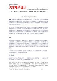
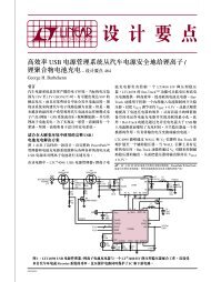
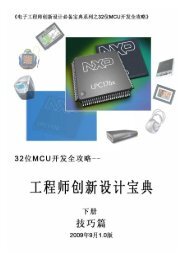
AN992<strong>Sensorless</strong> <strong>BLDC</strong> <strong>Motor</strong> <strong>Control</strong> <strong>Using</strong> <strong>dsPIC30F2010</strong>Author:Stan D’SouzaTechnical FellowINTRODUCTIONThis application note describes how to provide sensorless<strong>BLDC</strong> motor control with the <strong>dsPIC30F2010</strong>Digital Signal <strong>Control</strong>ler. The technique used is basedon another Microchip application note: <strong>Using</strong> thedsPIC30F for <strong>Sensorless</strong> <strong>BLDC</strong> <strong>Control</strong> (AN901).This application note explains how to apply the<strong>dsPIC30F2010</strong> device to the hardware and softwaredescribed in AN901, which uses the dsPIC30F6010device and dsPICDEM MC1 <strong>Motor</strong> <strong>Control</strong> DevelopmentBoard. The 80-pin dsPIC30F6010 has 144Kbytes of Flash Program Memory, 8 Kbytes of RAMavailable and abundant I/O. The 28-pin<strong>dsPIC30F2010</strong>, on the other hand, has limited I/O, only12 Kbytes of Flash program memory and 512 bytes ofRAM. As you can see, the resources are finite.This application note prescribes changes to the hardware,software and user interface described in AN901to facilitate the easy transfer of the code to the<strong>dsPIC30F2010</strong> device. You will want to thoroughlyreview AN901 for details on <strong>BLDC</strong> sensorless designusing the dsPIC30F. Functionally, the code does notchange, so all <strong>BLDC</strong> control functions available anddescribed in AN901 are still the same.HARDWARE REQUIREDYou will need the following hardware to implement thedescribed motor control application:• PICDEM MCLV Development Board (Figure 1)• Hurst DMB0224C10002 CL B 6403 24 V <strong>BLDC</strong><strong>Motor</strong>• 24 VDC Power SupplyYou can purchase these items from Microchip as acomplete kit or as individual components. Check theDevelopment Tools section of the Microchip web sitefor ordering information.HARDWARE MODIFICATIONSFigure 2 is a simplified block diagram for a <strong>Sensorless</strong><strong>BLDC</strong> motor control application. This diagram will helpyou develop your own hardware, if you so choose, todrive a sensorless <strong>BLDC</strong> motor. Schematics for thePICDEM MCLV board are included in Appendix A.FIGURE 1:PICDEM MCLV DEVELOPMENT BOARD© 2005 Microchip Technology Inc. DS00992A-page 1
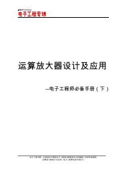
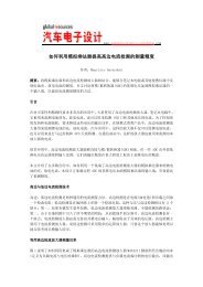
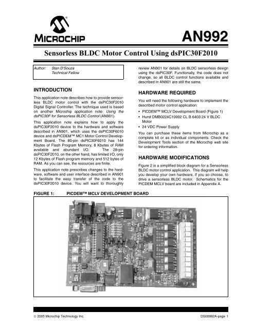
AN992FIGURE 2:PICDEM MCLV BOARD FUNCTIONALITY<strong>dsPIC30F2010</strong>PWM3HPWM3LPWM2HPWM2LPWM1HPWM1LFLTAAN0AN1AN2AN3AN4AN5FaultVDCDemand3-PhaseInverterIBUSR49 R41 R34 R36Phase Terminal Voltage FeedbackR44R52VDC<strong>BLDC</strong>VBUSR63R64Except for the <strong>dsPIC30F2010</strong> device, the basic blockdiagram is exactly the same as that used in AN901.• A pot selects the demand for the speed.• VBUS voltage is sensed as VDC using resistorpairs R63/R64. VDC/2 is used as the “zerocrossing”voltage for back EMF sensing.• Feedback voltage is sensed using resistor pairsR34/R36, R41/R44 and R49/R52.• Current feedback is provided through a simpleoperational amplifier circuit (U10A)• Fault input is received through a comparatorcircuit (U7D) connected with the current feedbackcircuit. The current is sensed using a 0.1 ohmresistor (R26). The current gain is 11 and thethreshold of the comparator can be adjusted usingpot R60.You can very easily adjust the values of the resistors toaccommodate the current capabilities of the motorbeing used for the application. The motor drive circuit,on the other hand, is designed to drive a 24V <strong>BLDC</strong>motor. You can change the drive requirement of themotor (refer to the PICDEM MCLV DevelopmentBoard User’s Guide for details on how to change thehardware for use with motors greater or less than 24V).On the low side, the voltage limit is 10V. On the highside, the voltage limit is 40V. It is important to note thatthe heat sink on the IGBTs have very limited heat dissipation,so high power requirements may not be easilymet with the PICDEM MCLV board.To use the PICDEM MCLV board for this application,use the jumper settings shown in Table 1 and the motorconnections shown in Table 2.TABLE 1: JUMPER SETTINGS FORPICDEM MCLV BOARDJumper<strong>Sensorless</strong> <strong>Control</strong>J7, J11, J13 Short between 2-3J15OpenJ8,J12,J14OpenJ10, J16, J17, J19 OpenTABLE 2:Connector J9LabelM1M2M3GMOTOR CONNECTIONS<strong>Sensorless</strong> <strong>Control</strong>Phase C (Red)Phase A (White)Phase B (Black)Ground (Green) If availableThe colors referenced in Table 2 are as per the Hurst24V motor available from Microchip. The ground wire issometimes not available on some motors.Once the code is developed and downloaded to thesystem, you will need to press switch S2 to start andstop the motor. The pot marked REF (R14) sets thedemand for the speed. It is rotated clockwise toincrease the speed of the motor.Due to the limited I/O on the <strong>dsPIC30F2010</strong>, the LEDson the board are not used to signal fault conditions.Instead, fault conditions are displayed on Windows®HyperTerminal® on your PC using the serial port.DS00992A-page 2© 2005 Microchip Technology Inc.
AN992PROGRAMMING THE <strong>dsPIC30F2010</strong>The <strong>dsPIC30F2010</strong> can be programmed using thePICDEM MCLV board. Due to the limited I/O resourceson the <strong>dsPIC30F2010</strong>, the serial port is shared with theprogramming pins. When you are ready to program thepart, DIP switch S4 should have its TAB in the PRGMdirection. When programming is completed, the DIPswitches must be moved to the DEBUG position to executethe code. If the IDC2 is connected to the PICDEMMCLV board as a debugger, then the connector at J6should be attached. If, however the ICD2 is being usedas a programmer, then the connector at J6 should beunplugged from the ICD2 for normal execution.The following configuration settings are required for theapplications to work on a PICDEM MCLV board:Oscillator Source:Primary OscillatorPrimary Oscillator Mode: XT w/PLL 8xComm Channel Select: EMUC2 and EMUD2Other settings can be enabled or disabled as needed,or modified in the application.SOFTWARE MODIFICATIONS:The software has not been modified significantly fromthat described in AN901. However, the user interface tothe LCD and the debug routines have been removed.The LCD interface has been replaced by the SerialUser Interface mentioned in the next section. The UserInterface does add to the code space and will require adsPIC30F3010 device during the development stage ofthe application.During the development mode you must set:#define DEVELOPMODE TRUEThis setting in the def.s file allows for all the conditionalstatements in the code to automatically enablethe UART and run the user interface mode. Once thecode has been fully developed, you can then select:#define DEVELOPMODE FALSEThis setting in the defs.s file disables the serial userinterface and hard codes the parameters to Flashmemory.To ensure that the code fits into the <strong>dsPIC30F2010</strong>,you must use the space optimization option in the C30compiler options. From the MPLAB Main menu, selectProject>Build Options>Project. When the BuildOptions dialog displays, select the MPLAB® C30 taband set Categories>Optimization>Optimization level>s(for space optimized).Note:The source code for this application isavailable on the Microchip web site(www.Microchip.com), appended to theelectronic (pdf) version of this applicationnote.USER INTERFACEThe user interface is necessary to tune the differentparameters used in the sensorless <strong>BLDC</strong> motor controlapplications. There are 45 user parameters that can bemodified in the applications. For more details on theseparameters, their functions/uses and how to tune them,refer to the <strong>Using</strong> the dsPIC30F for <strong>Sensorless</strong> <strong>BLDC</strong><strong>Control</strong> (AN901) application note.In AN901, the user parameters are modified using anLCD display and key switches. Since an LCD displayis not available on the PICDEM MCLV board, the userinterface has been modified to a 2 wire serial interface.The new user interface for this application uses theRS-232 port on the <strong>dsPIC30F2010</strong> connected to acommunication terminal (e.g., WindowsHyperTerminal) running at 19200 Baud.The communication terminal is then used to changeparameters in the user interface. All the parameters inAN901 that were set on the PICDEM MC1 <strong>Motor</strong> <strong>Control</strong>Development Board using the LCD screen can nowbe set through the serial interface.Table 3 lists the parameter names, abbreviations anddescriptions. A total of 45 control parameters are availablefor the user interface.The parameters are categorized by:• <strong>Motor</strong> Parameters - parameters that relate to themotor• Starting Parameters - parameters that relate tothe starting ramp• <strong>Control</strong> Parameters - parameters that relate tothe different PI or PID control parameters used inthe software• Limit Parameters - parameters that relate to thevarious limit settings in the software• Board Parameters - parameters that relate to thecomponents on the board and how they interactwith the software© 2005 Microchip Technology Inc. DS00992A-page 3
AN992TABLE 3:MOTOR CONTROL PARAMETERSFor This Parameter Type This Abbreviation Comment<strong>Motor</strong> ParametersDIRECTIONDD 0 orDD 10 = Forward1 = BackwardNo. <strong>Motor</strong> Poles MP Number of <strong>Motor</strong> PolesBlanking CountBC Windmilling DemWD Starting ParametersLock Pos.1 Time LP1T In 10-msec intervalsLock Pos.2 Time LP2T In 10-msec intervalsLock Pos.1 Dem LP1D In PWM duty cycle percentageLock Pos.2 Dem LP2D In PWM duty cycle percentageRamp Start Speed RSS Ramp Start Speed in RPMRamp End Speed RES Ramp End Speed in RPMRamp Start Dem RSD In PWM duty cycle percentageRamp End Dem RED In PWM duty cycle percentageRamp Duration RD In 10 msec intervalsTolerance CheckTC Auto Re-acquire ARA 0 or ARA 1 0 = disable1 = enableStarting <strong>Control</strong> SC 0and SC 1Acquire MethodAM 0 orAM 10 = Voltage <strong>Control</strong>1 = Current <strong>Control</strong>0 = Method 11 = Method 2ZeroX Enable Spd ZXES Speed at which zero crossing is enabledDS00992A-page 4© 2005 Microchip Technology Inc.
AN992TABLE 3:MOTOR CONTROL PARAMETERS (CONTINUED)For This Parameter Type This Abbreviation Comment<strong>Control</strong> ParametersCONTROL MODE CM 0,CM 1,CM 2 orCM 30 = Closed Volts1 = Closed Current2 = Open Volts3 = Open CurrentPhase Adv. Enable Spd PAES Phase Adv. SlopePAS Current P GainCKP Current I GainCKI Current D GainCKD Speed P GainSKP Speed I GainSKI Voltage DemandVD Volts P GainVKP Volts I GainVKI Limit ParametersStall Time LimitSTL Over Speed Limit OSL Over Speed Limit in RPMOver Volts LimitOVL Over Current LimOCL Board ParametersCurrent Scale XCSX Current Scale /CSD Volts Scale XVSX Volts Scale /VSD Zero X Level ThdZXL Acquire ThreshldAT Acquire Level TdAL Rotation TimeoutRT Pot / for DutyPDD Pot / for CurrntPDC Pot X for SpeedPXS Braking Ramp TBRT © 2005 Microchip Technology Inc. DS00992A-page 5
AN992USING THE SERIAL USERINTERFACEThe user parameters can only be modified during thestandby or reset state of the system. When the motor isrunning, the communications terminal displays thespeed and the percentage duty cycle of the PWM.The terminal must be connected to the PICDEM MCLVboard at the RS232 connector (J1) and set to operatewith these parameters:Bits per second 19200Data bits 8ParityNoneStop bits 1Flow controlNoneThe command set is case sensitive. If you type acommand incorrectly, the message shown in Figure 3displays.To get more information about the command set, type?? In response, the message shown in Figure 4 promptsfor a more specific request.To get information about a specific category of commands,type a question mark followed by the letter thatcorresponds to the command set category.FIGURE 3:INCORRECT COMMAND MESSAGEFIGURE 4:COMMAND SET HELP MENUDS00992A-page 6© 2005 Microchip Technology Inc.
AN992<strong>Motor</strong> Parameters<strong>Motor</strong> Parameters are displayed by typing:?MThe response message lists the motor parameters anddisplays their current value, as shown in Figure 5. Tochange any of the parameters, you type the parameterabbreviation followed by the new value (separated by aspace).The DIRECTION parameter (DD) uses only two parametervalues: ‘0’ or ‘1’.To change the direction of themotor rotation, you type:DD1Note that DD is upper case and there is a spacebetween the parameter abbreviation and the value 1.The command and its response are shown in Figure 6.The value has changed from ‘00000’ to ‘00001’ (theopposite direction).Suppose you want to change the number of motorpoles from 10 to 8. You would type:MP8This command and its response are shown in Figure 7.The value has changed from ‘00010’ to ‘00008’.FIGURE 5:MOTOR PARAMETERSFIGURE 6:MOTOR DIRECTION COMMAND AND RESPONSE© 2005 Microchip Technology Inc. DS00992A-page 7
AN992FIGURE 7:MOTOR POLES COMMAND AND RESPONSE<strong>Control</strong> Parameters:The <strong>Control</strong> Parameters and their current values aredisplayed in response to the ‘?C’ command, as shownin Figure 8.To change a control parameter, type the parameterabbreviation followed by the desired value. For example,if the Speed Integral Gain needs to go from 40 to200, you would type ‘SKI 200’.FIGURE 8:CONTROL PARAMETERSDS00992A-page 8© 2005 Microchip Technology Inc.
AN992Starting ParametersThe Starting Parameters fine tune the sensorless startingalgorithm and are probably the most often modifiedparameters. Because some of the parameters are variedby tens of milliseconds, please note the commentsin Table 3 and carefully review AN901.FIGURE 9:STARTING PARAMETERS© 2005 Microchip Technology Inc. DS00992A-page 9
AN992Limit ParametersThe limit parameters are shown in Figure 10.FIGURE 10:LIMIT PARAMETERSBoard ParametersThe board parameters are shown in Figure 11. Refer toAN901 for details on these parameters.FIGURE 11:BOARD PARAMETERSDS00992A-page 10© 2005 Microchip Technology Inc.
AN992Run Time ModeAs noted before, the parameters can be viewed inStandby mode only. During the actual operation of themotor, the speed of the motor and the percentage DutyCycle being used by the motor PWM are constantlyupdated, as shown in Figure 12.FIGURE 12:RUN TIME DISPLAY OF SPEED AND PWM DUTY CYCLEFault ConditionIf a fault condition occurs during the starting or operationof the motor, it is reported as shown in Figure 13.The faults reported include:• FAILED TO START• OVER CURRENT• OVER VOLTAGE• HARDWARE TRIP• OVER SPEED• SENSORLESS LOST• STALLEDTo reset the fault or stop the motor, you must press S2on the board. When the system resets, you can edit thenecessary parameters.FIGURE 13:FAULT MESSAGE© 2005 Microchip Technology Inc. DS00992A-page 11
AN992CONCLUSIONThe 28-pin <strong>dsPIC30F2010</strong> is an ideal low-cost solutionto control a sensorless <strong>BLDC</strong> motor. <strong>Using</strong> the flexibleserial user interface described in this application note,you can fine tune the application parameters requiredto start and run a sensorless <strong>BLDC</strong> motor applicationas described in detail in AN901.DS00992A-page 12© 2005 Microchip Technology Inc.
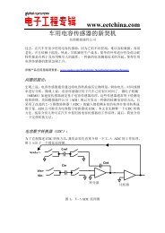
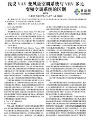
AN992APPENDIX A:SCHEMATICSFIGURE A-1: <strong>BLDC</strong> MOTOR CONTROL BOARD (SHEET 1 OF 2)© 2005 Microchip Technology Inc. DS00992A-page 13
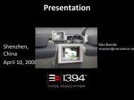
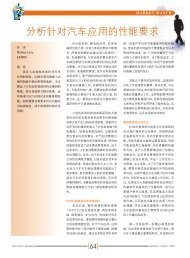
AN992FIGURE A-2: <strong>BLDC</strong> MOTOR CONTROL BOARD (SHEET 1 OF 2)2 HIN VB 83 LIN HO7VS 6VCC 1LO 5COM42 HIN VB83 LIN HO 7VS 6VCC 1LO5COM 42 HIN VB83 LIN HO7VS6VCC1LO5COM4DS00992A-page 14© 2005 Microchip Technology Inc.
Note the following details of the code protection feature on Microchip devices:• Microchip products meet the specification contained in their particular Microchip Data Sheet.• Microchip believes that its family of products is one of the most secure families of its kind on the market today, when used in theintended manner and under normal conditions.• There are dishonest and possibly illegal methods used to breach the code protection feature. All of these methods, to ourknowledge, require using the Microchip products in a manner outside the operating specifications contained in Microchip’s DataSheets. Most likely, the person doing so is engaged in theft of intellectual property.• Microchip is willing to work with the customer who is concerned about the integrity of their code.• Neither Microchip nor any other semiconductor manufacturer can guarantee the security of their code. Code protection does notmean that we are guaranteeing the product as “unbreakable.”Code protection is constantly evolving. We at Microchip are committed to continuously improving the code protection features of ourproducts. Attempts to break Microchip’s code protection feature may be a violation of the Digital Millennium Copyright Act. If such actsallow unauthorized access to your software or other copyrighted work, you may have a right to sue for relief under that Act.Information contained in this publication regarding deviceapplications and the like is provided only for your convenienceand may be superseded by updates. It is your responsibility toensure that your application meets with your specifications.MICROCHIP MAKES NO REPRESENTATIONS OR WAR-RANTIES OF ANY KIND WHETHER EXPRESS OR IMPLIED,WRITTEN OR ORAL, STATUTORY OR OTHERWISE,RELATED TO THE INFORMATION, INCLUDING BUT NOTLIMITED TO ITS CONDITION, QUALITY, PERFORMANCE,MERCHANTABILITY OR FITNESS FOR PURPOSE.Microchip disclaims all liability arising from this information andits use. Use of Microchip’s products as critical components inlife support systems is not authorized except with expresswritten approval by Microchip. No licenses are conveyed,implicitly or otherwise, under any Microchip intellectual propertyrights.TrademarksThe Microchip name and logo, the Microchip logo, Accuron,dsPIC, KEELOQ, microID, MPLAB, PIC, PICmicro, PICSTART,PRO MATE, PowerSmart, rfPIC, and SmartShunt areregistered trademarks of Microchip Technology Incorporatedin the U.S.A. and other countries.AmpLab, FilterLab, Migratable Memory, MXDEV, MXLAB,PICMASTER, SEEVAL, SmartSensor and The Embedded<strong>Control</strong> Solutions Company are registered trademarks ofMicrochip Technology Incorporated in the U.S.A.Analog-for-the-Digital Age, Application Maestro, dsPICDEM,dsPICDEM.net, dsPICworks, ECAN, ECONOMONITOR,FanSense, FlexROM, fuzzyLAB, In-Circuit SerialProgramming, ICSP, ICEPIC, Linear Active Thermistor,MPASM, MPLIB, MPLINK, MPSIM, PICkit, PICDEM,PICDEM.net, PICLAB, PICtail, PowerCal, PowerInfo,PowerMate, PowerTool, rfLAB, rfPICDEM, Select Mode,Smart Serial, SmartTel, Total Endurance and WiperLock aretrademarks of Microchip Technology Incorporated in theU.S.A. and other countries.SQTP is a service mark of Microchip Technology Incorporatedin the U.S.A.All other trademarks mentioned herein are property of theirrespective companies.© 2005, Microchip Technology Incorporated, Printed in theU.S.A., All Rights Reserved.Printed on recycled paper.Microchip received ISO/TS-16949:2002 quality system certification forits worldwide headquarters, design and wafer fabrication facilities inChandler and Tempe, Arizona and Mountain View, California inOctober 2003. The Company’s quality system processes andprocedures are for its PICmicro ® 8-bit MCUs, KEELOQ ® code hoppingdevices, Serial EEPROMs, microperipherals, nonvolatile memory andanalog products. In addition, Microchip’s quality system for the designand manufacture of development systems is ISO 9001:2000 certified.© 2005 Microchip Technology Inc. DS00992A-page 15
WORLDWIDE SALES AND SERVICEAMERICASCorporate Office2355 West Chandler Blvd.Chandler, AZ 85224-6199Tel: 480-792-7200Fax: 480-792-7277Technical Support:http://support.microchip.comWeb Address:www.microchip.comAtlantaAlpharetta, GATel: 770-640-0034Fax: 770-640-0307BostonWestborough, MATel: 774-760-0087Fax: 774-760-0088ChicagoItasca, ILTel: 630-285-0071Fax: 630-285-0075DallasAddison, TXTel: 972-818-7423Fax: 972-818-2924DetroitFarmington Hills, MITel: 248-538-2250Fax: 248-538-2260KokomoKokomo, INTel: 765-864-8360Fax: 765-864-8387Los AngelesMission Viejo, CATel: 949-462-9523Fax: 949-462-9608San JoseMountain View, CATel: 650-215-1444Fax: 650-961-0286TorontoMississauga, Ontario,CanadaTel: 905-673-0699Fax: 905-673-6509ASIA/PACIFICAustralia - SydneyTel: 61-2-9868-6733Fax: 61-2-9868-6755China - BeijingTel: 86-10-8528-2100Fax: 86-10-8528-2104China - ChengduTel: 86-28-8676-6200Fax: 86-28-8676-6599China - FuzhouTel: 86-591-8750-3506Fax: 86-591-8750-3521China - Hong Kong SARTel: 852-2401-1200Fax: 852-2401-3431China - ShanghaiTel: 86-21-5407-5533Fax: 86-21-5407-5066China - ShenyangTel: 86-24-2334-2829Fax: 86-24-2334-2393China - ShenzhenTel: 86-755-8203-2660Fax: 86-755-8203-1760China - ShundeTel: 86-757-2839-5507Fax: 86-757-2839-5571China - QingdaoTel: 86-532-502-7355Fax: 86-532-502-7205ASIA/PACIFICIndia - BangaloreTel: 91-80-2229-0061Fax: 91-80-2229-0062India - New DelhiTel: 91-11-5160-8631Fax: 91-11-5160-8632Japan - KanagawaTel: 81-45-471- 6166Fax: 81-45-471-6122Korea - SeoulTel: 82-2-554-7200Fax: 82-2-558-5932 or82-2-558-5934Malaysia - PenangTel:011-604-646-8870Fax:011-604-646-5086Philippines - ManilaTel: 011-632-634-9065Fax: 011-632-634-9069SingaporeTel: 65-6334-8870Fax: 65-6334-8850Taiwan - KaohsiungTel: 886-7-536-4818Fax: 886-7-536-4803Taiwan - TaipeiTel: 886-2-2500-6610Fax: 886-2-2508-0102Taiwan - HsinchuTel: 886-3-572-9526Fax: 886-3-572-6459EUROPEAustria - WeisTel: 43-7242-2244-399Fax: 43-7242-2244-393Denmark - BallerupTel: 45-4450-2828Fax: 45-4485-2829France - MassyTel: 33-1-69-53-63-20Fax: 33-1-69-30-90-79Germany - IsmaningTel: 49-89-627-144-0Fax: 49-89-627-144-44Italy - MilanTel: 39-0331-742611Fax: 39-0331-466781Netherlands - DrunenTel: 31-416-690399Fax: 31-416-690340England - BerkshireTel: 44-118-921-5869Fax: 44-118-921-582004/20/05DS00992A-page 16© 2005 Microchip Technology Inc.