CP Propeller Equipment - Martin's Marine Engineering Page
CP Propeller Equipment - Martin's Marine Engineering Page
CP Propeller Equipment - Martin's Marine Engineering Page
- No tags were found...

Create successful ePaper yourself
Turn your PDF publications into a flip-book with our unique Google optimized e-Paper software.
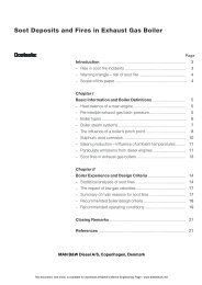
Technical Calculation andServicesArrangement drawingsProvided MAN B&W Alpha have adequateinformation on the ship hull, anarrangement drawing showing a suitablelocation of the propulsion plant inthe ship can be carried out with dueconsideration to a rational lay–out ofpropeller shaft line and bearings.In order to carry out the above arrangementdrawing MAN B&W Alpha needthe following drawings: Ship lines plan Engine room arrangement General arrangementMoreover, to assist the consulting firmor shipyard in accomplishing their ownarrangement drawings, drawings of ourpropeller programme can be transmittedby E–mail or a disk can be forwardedby regular post. The disks arecompatible with various CAD programmes.Should you require furtherinformation, please contact MAN B&WAlpha.Plant information bookAfter the contract documentation hasbeen completed a Plant InformationBook will be forwarded. This book willcomprise all necessary detailed drawings,specifications and installation instructionsfor our scope of supply.CAE programmes are used for makingalignment calculations, epoxy chockcalculations, torsional vibration calculationsetc. In the following a brief descriptionis given of some of our CAEprogrammes and software service.The alignment calculations ensure acceptableload distribution of the sterntube bearings and shaft bearings.Torsional vibrationsA comprehensive analysis of the torsionalvibration characteristics of thecomplete propulsion plant is essentialto avoid damage to the shafting due tofatigue failures.Based on vast experience with torsionalvibration analysis of MAN B&Wtwo and four–stroke propulsion plants,the VBS and VB propeller equipment isdesigned with optimum safety againstpremature failure due to fatigue. Stressraisers in the shafting or servo unit areminimized using finite element techniques.2 04 01 13–6.0mm–0.200.20.40.6Shaftline for S4633When the propeller is delivered with aMAN B&W engine a complete torsionalvibration analysis in accordance withthe Classification Society rules is performed.This includes all modes ofoperation including simulation of enginemisfire.When the total propulsion plant is designedand manufactured by MANB&W, the optimum correlation betweenthe individual items exists. The extensiveknow–how ensures that the optimumsolution is found as regards minimizingstresses in connection withtorsional vibration calculations. Fig 35shows the result of a torsional vibrationcalculation.1 2 3 4 5 6 7 81 23 4 5mAlignment instructionsFor easy alignment of the propellershaft line, alignment calculations aremade and a drawing with instructions isgiven in the Plant Information Book, fig34.BearingNo.12345Bearing reaction(kN)43.1006.979–0.04346.14746.318Vertical displacement(mm)0.00E+000.00E+003.56E–013.60E–013.60E–01Fig 34: Calculated reactions and deflections in bearingsAngular deflection(rad)3.11E–041.83E–042.03E–057.28E–064.81E–0622This document, and more, is available for download at <strong>Martin's</strong> <strong>Marine</strong> <strong>Engineering</strong> <strong>Page</strong> - www.dieselduck.net