Power Grid Analysis in VLSI Designs - SERC
Power Grid Analysis in VLSI Designs - SERC
Power Grid Analysis in VLSI Designs - SERC

You also want an ePaper? Increase the reach of your titles
YUMPU automatically turns print PDFs into web optimized ePapers that Google loves.
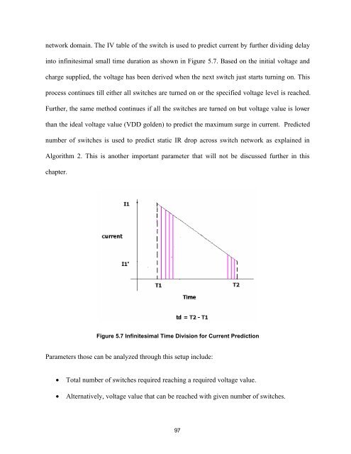
network doma<strong>in</strong>. The IV table of the switch is used to predict current by further divid<strong>in</strong>g delay<strong>in</strong>to <strong>in</strong>f<strong>in</strong>itesimal small time duration as shown <strong>in</strong> Figure 5.7. Based on the <strong>in</strong>itial voltage andcharge supplied, the voltage has been derived when the next switch just starts turn<strong>in</strong>g on. Thisprocess cont<strong>in</strong>ues till either all switches are turned on or the specified voltage level is reached.Further, the same method cont<strong>in</strong>ues if all the switches are turned on but voltage value is lowerthan the ideal voltage value (VDD golden) to predict the maximum surge <strong>in</strong> current. Predictednumber of switches is used to predict static IR drop across switch network as expla<strong>in</strong>ed <strong>in</strong>Algorithm 2. This is another important parameter that will not be discussed further <strong>in</strong> thischapter.Figure 5.7 Inf<strong>in</strong>itesimal Time Division for Current PredictionParameters those can be analyzed through this setup <strong>in</strong>clude:• Total number of switches required reach<strong>in</strong>g a required voltage value.• Alternatively, voltage value that can be reached with given number of switches.97