HFC-212 - Teledyne Hastings Instruments
HFC-212 - Teledyne Hastings Instruments
HFC-212 - Teledyne Hastings Instruments
- No tags were found...

You also want an ePaper? Increase the reach of your titles
YUMPU automatically turns print PDFs into web optimized ePapers that Google loves.
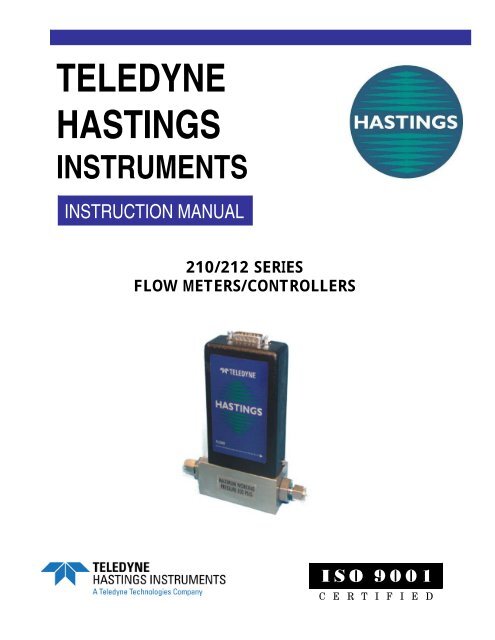
TELEDYNEHASTINGSINSTRUMENTSINSTRUCTION MANUAL210/<strong>212</strong> SERIESFLOW METERS/CONTROLLERSISO 9001C E R T I F I E D
Table of Contents1. GENERAL INFORMATION............................................................................................................................................ 41.1. FEATURES.................................................................................................................................................................... 41.2. SPECIFICATIONS........................................................................................................................................................... 51.3. OPTIONAL 4-20 MA CURRENT OUTPUT ....................................................................................................................... 51.4. OTHER ACCESSORIES................................................................................................................................................... 62. INSTALLATION AND OPERATION............................................................................................................................. 72.1. RECEIVING INSPECTION ............................................................................................................................................... 72.2. POWER REQUIREMENTS ............................................................................................................................................... 72.3. OUTPUT SIGNAL........................................................................................................................................................... 72.4. MECHANICAL CONNECTIONS....................................................................................................................................... 72.5. ELECTRICAL CONNECTIONS......................................................................................................................................... 82.6. OPERATION.................................................................................................................................................................. 82.7. OPERATION WITH EXTERNAL DEVICES ........................................................................................................................ 92.8. RANGE CHANGING:.................................................................................................................................................... 103. THEORY OF OPERATION ........................................................................................................................................... 123.1. OVERALL FUNCTIONAL DESCRIPTION: ...................................................................................................................... 123.2. SENSOR:..................................................................................................................................................................... 123.3. ELECTRONICS: ........................................................................................................................................................... 123.4. SHUNT: ...................................................................................................................................................................... 133.5. VALVE: ...................................................................................................................................................................... 134. MAINTENANCE.............................................................................................................................................................. 144.1. AUTHORIZED MAINTENANCE..................................................................................................................................... 144.2. TROUBLESHOOTING ................................................................................................................................................... 144.3. ADJUSTMENTS ...................................................................................................................................................... 154.4. FITTING AND SHUNT CHANGES:................................................................................................................................. 164.5. PRINTED CIRCUIT BOARD REPLACEMENT.................................................................................................................. 164.6. SENSOR REPLACEMENT: ............................................................................................................................................ 164.7. ORIFICE CHANGES: .................................................................................................................................................... 165. WARRANTY AND REPAIR .......................................................................................................................................... 175.1. WARRANTY REPAIR POLICY ...................................................................................................................................... 175.2. NON-WARRANTY REPAIR POLICY ............................................................................................................................. 17168-082010_ 210-<strong>212</strong> Meter/Controller Page 3 of 17
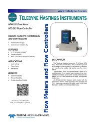
1. General InformationThe <strong>Hastings</strong> HFM-210 mass Flowmeter and <strong>HFC</strong>-<strong>212</strong> flow controller are designed to accurately measureand control mass flow over the range of 10 sccm to 30 slm, without corrections or compensations for gaspressure and temperature with an accuracy of better than ±1% FS. <strong>Hastings</strong> mass flow instruments do notrequire any periodic maintenance under normal operating conditions with clean gases. No damage will occurfrom the use of moderate overpressures (~500 psi/3.45MPa) or overflows. <strong>Instruments</strong> are normallycalibrated with the appropriate standard calibration gas (nitrogen) then a correction factor is used to adjust theoutput for the intended gas.1.1. Features• LINEAR BY DESIGN. The HFM-210/<strong>HFC</strong>-<strong>212</strong> series is inherently linear (no linearization circuitry isemployed). Should recalibration in the field be desired (a calibration standard is required), the customerneeds to simply set the zero and span points. There will be no appreciable linearity change of the instrumentwhen the flowing gas is changed.• MODULAR SENSOR. The HFM-210/<strong>HFC</strong>-<strong>212</strong> series incorporates a removable/replaceable sensor module.Field repairs to units can be achieved with a minimum of production line downtime.• METER SETTLING TIME. Changes in flow rate for the HFM-210 are detected in less than 2 seconds whenusing the fast-response circuitry.• LOW TEMPERATURE DRIFT. The temperature coefficient of span for the HFM-210/<strong>HFC</strong>-<strong>212</strong> series istypically less than 0.08% of full scale/°C from 15-45°C. The temperature coefficient of zero is typically lessthan 0.15 % of reading/°C from 0-50°C.• CURRENT LOOP. The 4-20 mA option gives the user the advantages of a current loop output to minimizeenvironmental noise pickup.168-082010_ 210-<strong>212</strong> Meter/Controller Page 4 of 17
loop is returned to the power supply ground, the load must be between 0 and 600 ohm. If it is returned to the-15VDC, the load must be between 600 and 1200 ohm. Failure to meet these conditions will cause failure ofthe loop transmitter.The 4-20 mA I/O option can accept a current input. The 0-5 VDC command signal on pin 6 can be replacedby a 4-20mA command signal. The loop presets an impedance of 75 ohms and is returned to the powersupply through the valve common.1.5. Other Accessories1.5.1. <strong>Hastings</strong> Power Supplies<strong>Hastings</strong> Power Pod power supply/display units are available in one and four channel versions. They convert100, 115 or 230VAC to the ±15 VDC required to operate the flow meter and provide a digital indication ofthe flow rate. Interface terminals for the retransmission of the flow meter analog output signal are located onthe rear of the panel.The Power Pod 100 and 400 models are built with controllers in mind but will work with meters as well. TheModel 40 is for flow meters only. Throughout this manual, when reference is made to a power supply, it isassumed the customer is using a <strong>Hastings</strong> power supply. <strong>Hastings</strong> PowerPod-100 and PowerPod-400 powersupplies are CE marked, but the Model 40 does not meet CE standards at this time. The Model 40 andPowerPod-100 are not compatible with 4–20 mA analog signals. With the PowerPod 400, individual channels’input signals, as well as their commands, become 4–20 mA compatible when selected. The PowerPod-400 alsosports a Totalizer feature. More information about the Power Pods can be found on the <strong>Hastings</strong> web site.http://www.teledyne-hi.com/products/powerpod-series.htm1.5.2. Interconnecting CablesCables are available from <strong>Hastings</strong>, in various lengths, to connect from the 15 pin "D" connector on the back ofthe Power Pod directly to any of the 200 series and 300 series flow instruments (including digital versions).More information about the available cables can be found in the Power Pod 400 bulletin on the <strong>Hastings</strong> website. http://www.teledyne-hi.com/pdfs/bulletins.htm168-082010_ 210-<strong>212</strong> Meter/Controller Page 6 of 17
2. Installation and OperationThis section contains the necessary steps to assist in getting a new Flowmeter /controller into operation asquickly and easily as possible. Please read the following thoroughly before attempting to install the instrument.2.1. Receiving InspectionCarefully unpack the <strong>Hastings</strong> HFM-210/<strong>HFC</strong>-<strong>212</strong> series instrument and any accessories that have also beenordered. Inspect for any obvious signs of damage to the shipment. Immediately advise the carrier whodelivered the shipment if any damage is suspected. Check each component shipped with the packing list.Insure that all parts are present (i.e., Flowmeter, power supply, cables, etc.). Optional equipment oraccessories will be listed separately on the packing list. There may also be one or more OPT-options on thepacking list. These normally refer to special ranges or special gas calibrations. They may also refer to specialhelium leak tests, or high pressure tests. In most cases, these are not separate parts, but special options ormodifications built into the Flowmeter.2.2. Power RequirementsThe HFM-210/<strong>HFC</strong>-<strong>212</strong> series requires ±15 VDC @ ±30 mA (HFM-210) +60 mA, -185 mA (<strong>HFC</strong>-<strong>212</strong>)for proper operation. The supply voltage should be sufficiently regulated to no more than 50 mV ripple. Thesupply voltage can vary from 14.0 to 16.0 VDC. Surge suppressors are recommended to prevent power spikesreaching the instrument. The <strong>Hastings</strong> power supply described in Section 1.4.2 satisfies these powerrequirements.The HFM-210/<strong>HFC</strong>-<strong>212</strong> series instruments have an integral 5 VDC ref. source. This stable voltage is on pin15 of the “D” connector and may be used for the command voltage.2.3. Output SignalThe standard output of the Flowmeter is a 0-5 VDC signal proportional to the flow rate. In the <strong>Hastings</strong>power supply the output is routed to the display, and is also available at the terminals on the rear panel. If a<strong>Hastings</strong> supply is not used, the output is available on pin 6 of the “D” connector and is referenced to pin 5. Itis recommended that the load resistance be no less that 2kΩ. If the optional 4-20 mA output is used, the loadimpedance must be selected in accordance with Section 1.3.2.4. Mechanical ConnectionsThe Flowmeter may be mounted in any position as long as the direction of gas flow through the instrumentfollows the arrow marked on the bottom of the Flowmeter case label. The preferred orientation is with theinlet and outlet fittings in a horizontal plane (if operating with a dense gas or at high pressures the instrumentmust be installed horizontally). When mounted in a different orientation the instrument should be re-zeroed atzero flow with the system pressurized to the expected operating pressure.The smallest of the internal passageways in the HFM-210/<strong>HFC</strong>-<strong>212</strong> series is the diameter of the sensor tube,which is 0.0125” (0.31 mm), so the instrument requires adequate filtering of the gas supply to preventblockage or clogging of the tube.The pressure regulator and the plumbing upstream must be of sufficient size to minimize changes in theupstream pressure. When switching from full flow to zero flow, the inlet pressure of instrument should rise tono more that 30% above the inlet pressure at full flow. In general, high capacity regulators and large internaldiameter plumbing help to make the system more stable. The pressure drop between the regulator and theinstrument due to line resistance should be minimized. The differential pressure across the unit should be lessthan 6” of H 2O at maximum flow.There are two 8-32 threaded holes, located on the bottom of the base that can be used to secure it to amounting bracket, if desired (screws provided). Other holes for special mounting can be added to the end capas desired.168-082010_ 210-<strong>212</strong> Meter/Controller Page 7 of 17
The standard inlet and outlet fittings for the 210/<strong>212</strong> are 0.25” and 0.125” Swagelok (optional VCR or VCOfittings). The O-rings for the end cap and the sensor are Viton (optional Kalrez or Neoprene). It is suggestedthat all connections be checked for leaks after installation. This can be done by pressurizing the instrument(do not exceed 500 psig unless the Flowmeter is specifically rated for higher pressures) and applying a dilutedsoap solution to the flow connections rated for higher pressures) and applying a diluted soap solution to theflow connections.2.5. Electrical ConnectionsIf a power supply from <strong>Hastings</strong> <strong>Instruments</strong> is used, installation consists of connecting the HFM-210/<strong>HFC</strong>-<strong>212</strong> series cable from the “D” connector on the rear of the power supply to the “D” connector on the top ofthe Flowmeter. If a different power supply is used, follow the instructions below when connecting the flowmeter.This HFM-210/<strong>HFC</strong>-<strong>212</strong> series requires <strong>Hastings</strong> cable #AF-8AM. Use of any other cable can severelydamage the instrument and void the warranty. Figure 2.1 shows the schematic layout for connecting theinstrument to an appropriate power supply.The power supply used must be capable of supplying +15VDC at 50mA and -15VDC at -200mA for eachcontroller. These voltages must be referenced to a common ground. Connect -15VDC to pin 9 and +15VDCto pin 11. Pins 5 and 12 are both commons and they must be connected together and to the groundconnection at the power supply. Do not connect them together at the flow controller as the resulting crosstalkcould result in flow instabilities. Pin 7 is the case ground. It should be connected to the cable shield ifavailable and to the AC ground to the power supply.Pin 6 is the output signal from the flow controller. This output will be 0-5VDC, 5VDC being 100% of rated orfull flow. Pin 14 is the command input. This should be a 0-5VDC signal and must be free of spikes or otherelectrical noise, as these will generate false flow commands that the controller would attempt to flow. Pin 15 isa well regulated +5.00VDC output reference. The reference is designed to provide the command signal for pin14 by connecting one end of a potentiometer to pin 15 and the other end to ground. The center lead wouldthen be connected to pin 14.If a valve override switch is not desired, the unit is ready for use at this time. If the override switch is desired,connect the center pin of a single pole, three-position switch with the center off position to pin 8. Connect+15VDC to one end of the switch, and -15VDC to the other end. This will result in the valve being full openwhen +15VDC is supplied to pin 8, off when -15VDC is supplied and auto-control when there is noconnection to pin 8 (OPEN-AUTO-CLOSE). This setup will be adequate for most purposes, but there will bea small delay for capacitors tocharge between switch operationand control override.2.6. OperationThe standard instrument outputis a 0 - 5 VDC out and the signalis proportional to the flow i.e., 0volts = zero flow and 5 volts =100% of rated flow. The 4 - 20mA option is also proportional toflow, 4 mA = zero flow and 20mA = 100% of rated flow. It issuggested that all connections bechecked for leaks after installation.This can be done by pressurizingthe instrument (do not exceed500 psig unless the instrument isspecifically rated for higherpressures) and applying a dilutedsoap solution to the connections.Fig 2.1168-082010_ 210-<strong>212</strong> Meter/Controller Page 8 of 17
2.6.1. Operating ConditionsFor proper operation, the combination of ambient temperature and gas temperature must be such that theFlowmeter temperature remains between 0 and 50°C. (Most accurate measurement of flow will be obtained ifthe Flowmeter is zeroed at operating temperature as temperature shifts result in some zero offset.) The HFM-210/<strong>HFC</strong>-<strong>212</strong> series is intended for use in non-condensing environments only. Condensate or any otherliquids which enter the Flowmeter may destroy its electronic components.2.6.2. Zero CheckTurn the power supply on if not already energized. Allow for a 1 hour warm-up. Stop all flow through theinstrument and wait 2 minutes. Caution: Do not assume that all metering valves completely shut off the flow.Even a slight leakage will cause an indication on the meter and an apparent zero shift. For the standard 0-5VDC output, adjust the zero potentiometer located on the lower outlet side of the Flowmeter until the meterindicates zero. For the optional 4-20 mA output, adjust the zero potentiometer so that the meter indicatesslightly more than 4 mA, i.e. 4.03 to 4.05 mA. This slight positive adjustment ensures that the 4-20 mAcurrent loop transmitter is not in the cut-off region. The error induced by this adjustment is approximately0.3% of full scale. This zero should be checked periodically during normal operation. Zero adjustment isrequired if there is a change in ambient temperature, or vertical orientation of the Flowmeter/controller.2.6.3. High Pressure OperationWhen operating at high pressure, the increased density of gas will cause natural convection to flow through thesensor tube if the instrument is not mounted in a level position. This natural convection flow will beproportional to the system pressure. This will be seen as a shift in the zero flow output that is directlyproportional to the system pressure.2.6.4. Blending of GasesIn the blending of two gases, it is possible to maintain a fixed ratio of one gas to another. In this case, theoutput of one flow controller is used as the reference voltage for the set point potentiometer of a second flowcontroller. The set point potentiometer then provides a control signal that is proportional to the output signalof the first flow controller, and hence controls the flow rate of the second gas as a percentage of the flow rate ofthe first gas.EXAMPLE: Flow controller A has 0-100 slpm range with a 5.00 volt output at full scale. Flow controller Bhas 0-10 slpm range with a 5.00 volt output at full scale. If flow controller A is set at 80 slpm, its outputvoltage would be 4.00 volts (80 slpm/100 slpm x 5.00 volts = 4.00 volts). If the output signal from flowcontroller A is connected to the command potentiometer of flow controller B, it then becomes a variablereference voltage for flow controller B proportional to the flow rate of flow controller A.If the set point potentiometer of flow controller B is set at 50% of full scale, and the reference voltage from flowcontroller A is 4.00, then the command signal going to flow controller B would be 2.00 volts (4.00 volts x50.0% = 2.00 volts). The flow of gas through flow controller B is then controlled at 4 slpm (2.00 volts/5.00volts x 10 slpm = 4 slpm).The ratio of the two gases is 20:1 (80 slpm/4slpm). The % mixture of gas A is 95.2 (80slpm/84slpm and the %mixture of gas B is 4.8% (4 slpm/84 slpm).Should the flow of flow controller A drop to 78 slpm, flow controller B would drop to 3.9 slpm, hencemaintaining the same ratio of the mixture. (78 slpm/100slpm x 5v = 3.90v x 50% = 1.95v; 1.95v/5.00v x 10slpm = 3.9 slpm; 78 slpm:3.9 slpm = 20:1)2.7. Operation with External Devices2.7.1. Operation with a <strong>Hastings</strong> power supply.There are two controls for each flow controller connected to a <strong>Hastings</strong> power supply. A switch labeled“OPEN; AUTO; CLOSED” (valve over ride THPS 400 only) and a potentiometer labeled “COMMAND”.For normal operation, the valve over ride switch will be in the “AUTO” position. The “CLOSE” positionremoves all power from the valve, shutting off flow regardless of the command pot setting. The “OPEN”position applies full available valve voltage to the valve, causing it to open, regardless of the command potsetting. The “OPEN” position is useful for purging systems. It is recommended that the valve over rideswitch not be left in this position for extended periods of time, with no flow through the controller, as a smallpositive zero shift may be observed.168-082010_ 210-<strong>212</strong> Meter/Controller Page 9 of 17
The “COMMAND” pot adjusts the Analog command signal sent to the flow controller. The setting for eachcontroller connected to the power supply can be observed. (Depending on how the power supply was set up,the display could indicate in flow units or percent of full scale).2.7.2. Operation with a power supply other than a <strong>Hastings</strong>.The flow controller must be connected to the power source as specified in section 2.6. In general, a 0-5 VDCcommand signal proportional to the intended flow (0 volts = zero flow; 5 volts = 100% of rated flow) must beapplied to pin 14 of the “D” connector. A 0-5 VDC signal proportional to the flow rate through theinstrument will be present on pin 6 of the “D” connector. The control mode is selected via pin 8 of the “D”connector. Apply +15 volts for full open, -15 volts for closed and allow pin 8 to float for flow proportional tothe command voltage. Refer to your power supply manual for the specifics of implementing these parameters.2.7.3. Operation with an external sensor. (Fig. 2.2)In some instances, it might be desirable to use an external sensor to provide process information to the controlcircuitry in the flow controller. For example, you might want to control the pressure in a vacuum system byadjusting the rate at which the system is backfilled with a gas. The new, enhanced <strong>HFC</strong> series of flowcontrollers have provision for accepting a 0-5VDC output from an external sensor at pin 13 of the “D”connector. To activate this feature, the cover of the <strong>HFC</strong> must be removed to gain access to PC-828 andmove a jumper on JP1. JP1 is a three pin jumper block located just below the “D” connector. In the normaloperating mode, the jumper covers the bottom two pins. To select “External Sensor”, move the jumper to theupper two pins. This swaps the flow input to the controller circuit from the Flowmeter output to pin 13 of the“D” connector.2.7.4. Response to Command ChangesThe response of the control circuit to changes to the command signal is set at the factory for fast, stableresponse. Should it be necessary, the response is adjustable using the jumper labeled “JP4,” located in thecenter of PC-828.The fastest response to command changes is obtained when JP4 is covered by the jumper. This setup allowslarger overshoot and undershoots swings in the actual flow rate while the control circuit is establishing controlat the new command point. The slowest response to command changes is obtained when JP2 is uncovered.This setup results in no overshoot or undershoot in the actual flow rate as the controller circuit establishescontrol at the new command point.To adjust the response, you need a means of producing a step change in the command voltage from 10% offull scale to 100% of full scale. Follow the steps outlined below:To prevent loss of the unused jumper, place over one pin only on JP4.2.8. Range Changing:The range of the flow controller can be changed inthe field if recalibration facilities are available. Theflow controller may require a different orifice,which can be purchased separately from thefactory. A listing of the orifices available and theirflow rates can be found in Section 5.0. Theinstructions to change the flow range can be foundin Section 4.6.This section contains an overall functionaldescription of <strong>HFC</strong> Flow Controllers. Detailedschematics and parts lists can be found at the endof the manual in Section 6.0. In this section andother sections throughout this manual, when apower supply is mentioned, it is assumed that thecustomer has a <strong>Hastings</strong> Power Supply. Thesesections are not applicable if another type of powersupply is used.Fig 2.2168-082010_ 210-<strong>212</strong> Meter/Controller Page 10 of 17
2.9. Valve-Override ControlThe valve override control line provides a method to override the loop controller and open or close the valveregardless of the flow or command signals. During normal operation this line must be allowed to float freely.This will allow the loop control to open and close the valve as it requires. If the valve override line is forcedhigh (> +5 volts) the valve will be forced full open. If the valve-override line is forced negative (< -5 volts) thevalve will be forced closed.168-082010_ 210-<strong>212</strong> Meter/Controller Page 11 of 17
3. Theory of Operation3.1. Overall Functional Description:The <strong>HFC</strong> Flow Controller consists of a sensor,electronic circuitry, a shunt and a valve. The sensormeasures the flow rate from 0 to 10 sccm of the gasto be metered. The shunt divides the flow such thatthe flow through the sensor is a precise percentage ofthe flow through the shunt. The flow through thesensor and the shunt is always laminar. The circuitboard amplifies the sensor output and uses thisoutput to control the valve position. The valve is anautomatic metering solenoid type; its height off theseat is controlled by the voltage in its coil. All of thesecomponents working together result in a fast, stableflow controller.3.2. Sensor:Fig 3.1The <strong>Hastings</strong> HFM-210/<strong>HFC</strong>-<strong>212</strong> series operates on a unique thermal electric principle whereby a metalliccapillary tube is heated uniformly by a resistance winding attached to the midpoint of the capillary (see Figure3.1). Thermocouples TC-1 and TC-2 are welded at equal distances from the midpoint and develop equaloutputs at zero flow.When flow occurs through the tubing, heat is transferred from the tube to the gas on the inlet side, and fromthe gas back to the tube on the outlet side creating anasymmetrical temperature distribution (sees Figure 3.2).The thermocouples sense this decrease and increase inthe capillary tube temperature and produce a millivoltoutput signal proportional to that change.For a constant power input, the differential thermocoupleoutput is a function of the mass flow rate and the heatcapacity of the gas. Since the heat capacity of many gasesis relatively constant over wide ranges of temperature andpressure, the Flowmeter may be calibrated directly inmass units for those gases. Changes in gas compositionusually only require application of a simple multiplier tothe air calibration to account for the difference in heatcapacity and thus the Flowmeter is capable of measuringa wide variety of gases. The HFM sensor measuresapproximately 10 sccm, full scale shunt.Fig 3.23.3. Electronics:The <strong>Hastings</strong> HFM-210/<strong>HFC</strong>-<strong>212</strong> series uses a thermal flow sensor to measure through a capillary tube,which is a fixed percentage of the total flow through the instrument. This sensor develops an output signalproportional to flow which is approximately 1 mv full scale magnitude. This signal is amplified by the metercircuitry until is 0-5.00 VDC. This 5 volt output is sent back to the power supply and to the Flowmetercircuitry, if applicable. At the power supply the 5 volt output is sent to the terminals on the back and to thedecoding circuitry in the display which converts it to a 3-digit output.The controller circuitry utilizes the Command and the Flow voltages as input signals. The 0-5VDC commandsignal is subtracted from the 0-5VDC flow signal creating an error signal. This signal is amplified and causesthe solenoid valve to move. The amount and direction of the movement is dependent upon the value and thesign of the error signal, and tends to minimize the error signal.168-082010_ 210-<strong>212</strong> Meter/Controller Page 12 of 17
3.4. Shunt:Measurement of flow rates higher than the10 sccm full scale is achieved by dividingthe flow with a fixed ratio shuntingarrangement, as is illustrated in Figure 3.3.This is accomplished by placing themeasuring capillary tube parallel with oneor more dimensionally similar channels,called a laminar flow element (LFE).Therefore, the sensor only needs to heat thegas passing through the capillary tuberesulting in low power requirements, whileretaining all the mass measuringcharacteristics.Fig 3.3The HFM-210/<strong>HFC</strong>-<strong>212</strong> series has twopossible shunts. The low range shuntconsists of tubes inserted into a cylindricalbase. This shunt is adjustable for ranges from 0-10 sccm to 0-250 sccm (see Figure 3.4). The high rangeshunt consists of a corrugated stainless steel ribbon wound into a coil and fused. It is adjustable from 0-0.25slpm to 0-30 slpm ranges (see figure 3.5).Fig 3.4Fig 3.53.5. Valve:The control valve is an “automatic metering solenoid” valve. While most solenoids operate in either the fullyopen or fully closed state, the automatic metering solenoid valve is designed to control flow (see Figure 3.6). Aspring, connected to the plunger assembly,holds a magnetic plunger tightly against anorifice to shut off flow. The magnetic plungeris surrounded by an electrical coil, which whenenergized with electrical current lifts the plungeroff the orifice and allows flow to pass betweenthe orifice and the plunger seat. Controlling thecurrent through he coil controls the distancebetween the orifice and the plunger seat, thuseffectively controlling the flow through thevalve. This current is controlled by a feedbackloop that matches the transducer output withthe command voltage.Fig 3.6168-082010_ 210-<strong>212</strong> Meter/Controller Page 13 of 17
4. MaintenanceThis section contains service and calibration information. Some portions of the instrument are delicate. Useextreme care when servicing the flow controller. The potentiometer positions and the electrical componentsreferred to in the troubleshooting section can be found in Section 6.0 on the electrical component layoutdrawing.4.1. Authorized MaintenanceWith proper care in installation and use, the flow controller will require little or no maintenance. Ifmaintenance does become necessary, most of the instrument can be cleaned or repaired in the field. Someprocedures may require recalibration. Do not attempt these procedures unless facilities are available. Entryinto the sensor or tampering with the printed circuit board will void warranty. Do not perform repairs on theseassemblies while unit is still under warranty.4.2. TroubleshootingSYMPTOM: Output reads 40% of flow with no flow. Zero pot has no effect.CAUSE: Power supply locked up or shorted out.ACTION: Turn off power supply for a few seconds, then turn back on. If this proves ineffective, disconnectthe unit from the power supply. If power supply display does not return to zero, then a regulator chip in thepower supply is probably burned out. Check supply voltages and replace faulty regulator. If display returns tozero after disconnecting the power supply from the unit there is a short in the unit to ground.SYMPTOM: Override switch is in CLOSE position, but flow remains or 0.00 VDC is commanded and flowremains.CAUSE: Orifice out of adjustment or faulty op-ampACTION: Check valve voltage at connector pins 2 & 5. If voltage is less than 3.00 VDC, then turn orificeclockwise until flow stops. If voltage is greater than 3.00 VDC, replace U1; if less, replace transistor Q1.SYMPTOM: Output of unit is proportional to flow but extremely small and not correctable by span pot.CAUSE: Sensor is not being heated.ACTION: Unplug connector J1. Check the following resistance: The resistance between pins 2 & 3 of thesensor should be approximately 2500 ohms (see Figure 3.1 on page 8). The resistance between pins 1 & 4should be approximately 2.3 ohms. The resistance between pins 2 & 3 and the base of the sensor should beessentially infinite. If not, replace the sensor unit. If sensor reads O.K., check the voltage output on pins 2 & 3of the jack in the board. If it does not read approximately 22 VDC then replace op-amp U2.SYMPTOM: Sensor has proper resistance readings, but little or no output with flow.CAUSE: Plugged sensor.ACTION: Shut off gas supply and power supply. Remove cover and PC board from unit. Remove sensorassembly and examine. If sensor has evidence of plugging, clean or replace as applicableSYMPTOM: Flow controller oscillates.168-082010_ 210-<strong>212</strong> Meter/Controller Page 14 of 17
CAUSE: Flow controller not adjusted for the dynamics of the flow system.ACTION: Check upstream and downstream pressures. The gas supply regulator should not have excessivelockup when flow shuts off. Also ensure that there is not a large drop in pressure between the regulator andthe instrument due to line resistance. Oscillations can also be caused if a large flow restriction is pneumaticallyclose to the downstream end of the flow controller. The differential pressure across the unit must be between10-50 psig.SYMPTOM: Little or no flow, even with Valve Override switch OPEN.CAUSE: Plugged orifice.ACTION: Verify the presence of a 10-50 psig pressure across the instrument. If present, shut off gas supplyand power supply. Remove orifice per Section 4.9. Examine orifice. If plugged, clean or replace asapplicable. Reassemble valve.SYMPTOM: Flowmeter reads other than 0.00 VDC with no flow, or there is a small flow when Flowmeterreads 0.00 VDC.CAUSE: ZERO potentiometer is out of adjustment.ACTION: Shut off all flow. Adjust ZERO potentiometer until output reads 0.00 VDC.SYMPTOM: Flowmeter out of calibration and nonlinear.CAUSE:Leaks in gas inlet or outlet fittings.ACTION: Check all fittings for leaks by placing soap solution on all fittings between gas supply and finaldestination of gas. Check Flowmeter for leaks. Replace “O” rings if required or recalibrate as necessary.4.3. ADJUSTMENTS4.3.1. Calibration Procedure: (Figure 4.1)NOTE: Adjusting the SPAN pot will require the use of a calibrationreference in Step 5.1. Connect power cable to D connector as specified in Section 2.7.Allow instrument to warm up for 30 minutes with 10% flow andinstrument in AUTO position.2. Set ZERO (R13) potentiometer for 0.000 VDC output.3. Turn on gas supply to inlet of instrument. Put Valve Overrideswitch into CLOSE position. Adjust the orifice underneathcontroller to obtain zero flow. Put Valve Override switch intoAUTO. Ensure that full range flow can still be obtained atminimum inlet pressure.4. Set command to 100%. Adjust SPAN (R18) pot until the flowreference reads full scale flow (5.000 VDC). NOTE: Performthis step only if a calibrated reference Flowmeter is available.5. Record Flowmeter and flow reference outputs for flow rates of 20%, 40%, 60%, 80% and 100%.4.3.2. Miscellaneous adjustmentsPeriodically, during normal operation, the ZERO should be checked and adjusted when required. If systemparameters change, the RESPONSE pot may require a small adjustment for optimum stability. If theinstrument is not shutting completely off when Valve Override switch is in the CLOSE position, the orificemay require approximately 1/8 turn clockwise.168-082010_ 210-<strong>212</strong> Meter/Controller Page 15 of 17
4.4. Fitting and Shunt Changes:It is possible to change the fittings or the shunt, if necessary, as long as the instrument is recalibrated. Thesechanges should be made with the instrument removed from all electrical and mechanical connections. Thefitting on the downstream side of the instrument can be changed without needing recalibration. The upstreamfitting is modified, however, and removing it will void the calibration. To remove or replace the shunt,carefully remove the inlet fitting, retaining spring (if present) and the shunt, noting their order and properorientation. The shunt can be severely damaged if dropped. Examine the filter and shunt. If either is dirty orblocked, clean or replace as applicable. Reassembly is the reverse of the removal procedure. Recalibration ofthe <strong>HFC</strong> is necessary.4.5. Printed Circuit Board ReplacementIn the unlikely event that the PC board fails, it is easily removed from the instrument and replaced with a spareto minimize instrument downtime. Replacement of the PC board will require the instrument to be recalibratedper Section 4.3.1.Unplug the power cable from the top of the transducer. Remove the two jackscrews next to the “D” connectorand the two screws on the sides of the cover. Lift off the cover and unplug the four-wire sensor plug and thetwo wire valve plug, noting their orientation prior to removal.Remove the screw that holds the PC board to the sensor. Troubleshoot or replace as applicable. Installation isthe reverse of the above procedure. Recalibrate if any components were changed or if any potentiometers wereadjusted.4.6. Sensor Replacement:If the sensor fails or becomes plugged it can be removed. Remove the cover and the PC board per Section 4.5above. Remove the three bolts holding the sensor to the instrument base. Remove the sensor from the basenoting the two O-rings (Parker 2-005, V884-75) between the sensor and the base. If the sensor is plugged itcan be cleaned by running a fine wire (approximately 0.008" diameter) through the tube. If sensor needsreplacement, obtain another from the factory and install it. Ensure that O-rings are clean and intact. Install O-rings on seating surface, then carefully place sensor over O-rings and tighten down the three screws evenly.Replacement of sensor will require recalibration per Section 4.3.1.4.7. Orifice Changes:The orifice may require replacement if a flow range change is desired, if a large change in differential pressuresacross the valve is desired or in the event that a small orifice becomes plugged. Replacement orifices can beacquired from the factory having a Cv in the range of 0.0000263 to 0.129.To change the orifice in the <strong>HFC</strong>-<strong>212</strong> series, turn the instrument upside-down and turn the orificecounterclockwise with a 9/64" Allen wrench until it stops coming out. Then grasp the exposed orifice end andpull it straight out. See Figure 4.2.Prior to reinstallation of the orifice, inspect the twoO-rings mounted on it for damage. Replace if cut orgouged.Lubricate the O-rings slightly with a silicone basedgrease, and the threads with anti-galling compound.Push the orifice into its hole and screw it in until it isflush with the instrument base. Apply pressure to theinlet side of the instrument.Turn the Valve Override switch to CLOSE or unplugthe instrument. Screw the orifice in a few more turnsuntil the flow through the instrument stops, then turnit an additional 1/4 turn clockwise.168-082010_ 210-<strong>212</strong> Meter/Controller Page 16 of 17
5. Warranty and Repair5.1. Warranty Repair Policy<strong>Hastings</strong> <strong>Instruments</strong> warrants this product for a period of one year from the date of shipment to be free fromdefects in material and workmanship. This warranty does not apply to defects or failures resulting fromunauthorized modification, misuse or mishandling of the product. This warranty does not apply to batteries orother expendable parts, or to damage caused by leaking batteries or any similar occurrence. This warranty doesnot apply to any instrument which has had a tamper seal removed or broken.This warranty is in lieu of all other warranties, expressed or implied, including any implied warranty as tofitness for a particular use. <strong>Hastings</strong> <strong>Instruments</strong> shall not be liable for any indirect or consequential damages.<strong>Hastings</strong> <strong>Instruments</strong>, will, at its option, repair, replace or refund the selling price of the product if <strong>Hastings</strong><strong>Instruments</strong> determines, in good faith, that it is defective in materials or workmanship during the warrantyperiod. Defective instruments should be returned to <strong>Hastings</strong> <strong>Instruments</strong>, shipment prepaid, together with awritten statement of the problem and a Return Material Authorization (RMA) number.Please consult the factory for your RMA number before returning any product for repair. Collect freight willnot be accepted.5.2. Non-Warranty Repair PolicyAny product returned for a non-warranty repair must be accompanied by a purchase order, RMA form and awritten description of the problem with the instrument. If the repair cost is higher, you will be contacted forauthorization before we proceed with any repairs. If you then choose not to have the product repaired, aminimum will be charged to cover the processing and inspection. Please consult the factory for your RMAnumber before returning any product repair.TELEDYNE HASTINGS INSTRUMENTS804 NEWCOMBE AVENUEHAMPTON, VIRGINIA 23669 U.S.A.ATTENTION: REPAIR DEPARTMENTTELEPHONE (757) 723-6531TOLL FREE 1-800-950-2468FAX (757) 723-3925E MAILhastings_instruments@teledyne.comINTERNET ADDRESS http://www.teledyne-hi.comRepair Forms may be obtained from the “Information Request” section of the <strong>Hastings</strong> <strong>Instruments</strong> web site.168-082010_ 210-<strong>212</strong> Meter/Controller Page 17 of 17