
Create successful ePaper yourself
Turn your PDF publications into a flip-book with our unique Google optimized e-Paper software.
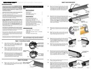
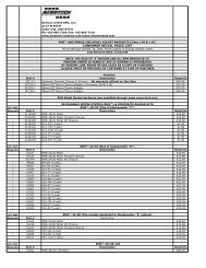
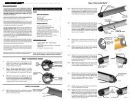
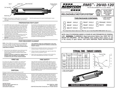
Fig-121/16” Vent HoleIgniter LeadMotor Hook SlotEjection ChargeContainerRMS - 29/40-120Fits All Kits Designed for “F & G” Motors18.Nozzle CapFig-12: Using scissors or a hobby knife, cut a corner off theclosed end of the nozzle cap to created a vent hole about1/16” wide.1. Install RMS motor into the rockets motor mount tube. Securethe motor into the rocket and prevent it from being ejectedat the time of ejection charge firing by using a motor hook,friction fit, or wrapping tape around the junction where themotor meets the end of the rocket motor tube. If using amotor hook, be sure to hold the hook away from the motorduring insertion into the motor tube to prevent the hookfrom scraping the motor casing. Position the hook tab intothe slotted recess in the aft closure.2. Prepare the rocket’s recovery system and then launch therocket by electrical means in the normal manner or asrecommended by the rocket manufacturer.3. MISFIRES: If a misfire occurs and a loaded <strong>AeroTech</strong>/RCSRMS motor does not ignite for any reason withinNOTE: Perform RMS motor cleanup as soon as possible aftermotor firing. Propellant and delay residues become difficult toremove 24 hours after motor firing. These residues can leadto corrosion of the metal parts. DISPENSE OF SPENT MOTORCOMPONENTS PROPERLY.1. After the motor has cooled down, remove the forward andaft closures. Using a wet wipe or damp paper towel,remove all delay, propellant and ejection charge residuefrom the closures.WARNING: FAILURE TO COMPLETELY REMOVE DELAYRESIDUE FROM THE INSIDE OF THE FORWARDCLOSURE CAN LEAD TO GAS LEAKAGE AROUNDFIRST AIDFor a minor burn, apply a burn ointment. For a severe burn,immerse the burned area in ice water at once and see aphysician as quickly as possible. In the unlikely event of oralingestion of the propellant, delay or ejection charge, inducevomiting and see a physician as quickly as possible. The<strong>AeroTech</strong>/RCS composite rocket propellant consists ofammonium perchlorate and a rubber like plastic elastomer.DISPOSALDamaged or defective reloads should be returned to RCS.PREPARATION FOR FLIGHTPOST-RECOVERY CLEANUPPush the nozzle cap over the nozzle to hold the igniter in place.five seconds of pressing the launch button, release the launchbutton and remove the safety key from the electrical launchcontroller. WAIT ONE MINUTE before approaching or allowinganyone else to approach the rocket. Keep your fingers andhands out from underneath the rocket and away from the possiblepath of the motor exhaust jet. Do not place any part of yourbody over the launch pad. Disconnect the igniter clip from theCOPPERHEAD igniter. Carefully remove the rocket from thelaunch pad. Keeping the motor nozzle pointed away from yourface and body - and away from any other person’s face or body -remove the red plastic nozzle cap and repeat the motorpreparation and launching process.THE FORWARD O-RING ON A SUBSEQUENT FLIGHT ANDDAMAGE TO YOUR RMS MOTOR FORWARD CLOSURE ANDROCKET VEHICLE.2. Remove the liner assembly and forward o-ring by pushing on thenozzle and discard. Remove the aft o-ring and discard.3. Using a wet wipe or a damp paper towel, wipe the inside of thecasing to remove all propellant residue.4. Apply a light coat of grease to all threads and the inside of themotor case. Reassemble parts and store in a dry place.FIRE SAFETYTests show that composite propellant RMS reload kits will notexplode in fires and normally will not ignite unless subjected todirect flame and then will burn slowly. Use water to fight fires inwhich <strong>AeroTech</strong>/RCS composite propellant RMS reload kits maybecome involved: direct the water at the <strong>AeroTech</strong>/RCS RMSreload kits to keep them below their 550˚F autoigniton temperature.Foam and carbon dioxide fire extinguishers will NOT extinguishburning propellant of the type used in <strong>AeroTech</strong>/RCS compositepropellant RMS reload kits.Division of RCS Rocket Motor Components, Inc.RELOADABLE MOTOR SYSTEM THIS PACKAGE CONTAINS:DO NOT OPENRELOAD KITUNTIL READYTO USE* = NAR CertifiedDelay timesF22-5J(4)* SINGLEE23-5T SINGLE F52-5T SINGLEF52T 1.29 36.6 18.0 80.0 11.7 52.0 4.3 123 E23-8T SINGLE F52-8T SINGLEF22-7J* SINGLEE23-11T SINGLEF52-11T SINGLEThe reload kits shown above are ONLY for use in <strong>AeroTech</strong>/RCS RMS-29/40-120 motors.NOTE: SALE TO PERSONS UNDER 18 YEARS OF AGE PROHIBITED BY FEDERALLAW. WARNING: FLAMMABLE: Read <strong>Instructions</strong> Before Use. KEEP OUT OFREACH OF CHILDREN. DO NOT SMOKE when loading these motors or usein the vicinity of open flames. FOR SAFE DISPOSAL READ INSTRUCTIONS.TYPICAL TIME - THRUST CURVES:Motor Propellant Total Impulse AverageLoadedTypeWeightThrustMotorWeightoz gms lb-sec N-sec lbs N oz gms<strong>E23T</strong> 0.61 17.4 9.0 40.0 5.2 23.0 3.7 104<strong>F22J</strong> 1.63 46.3 14.6 65.0 4.9 22.0 4.7 133T = Blue Thunder PropellantJ = Black Jack PropellantNOTICE: As we can not control the storage and use of ourproducts, once sold we cannot assume any responsibility forproduct storage, transportaion or usage. RCS shall not be heldresponsible for any personal injury or property damage resultingfrom the handling, storage or use of our product. The buyerassumes all risks and liabilities therefrom and accepts and uses<strong>AeroTech</strong>/RCS<strong>AeroTech</strong> DivisionRCS Rocket Motor Components, Inc.Cedar City, Utah 84720www.aerotech-rocketry.comproducts on these conditions. No warranty either expressed orimplied is made regarding <strong>AeroTech</strong>/RCS products, except forreplacement or repair, at RCS’s option, of those products whichare proven to be defective in manufacture within one year fromthe date of original purchase. For repair or replacement under thiswarranty, please contact RCS. Proof of purchase will be required.Note: Your state may provide additional rights not covered by thiswarranty.Part # 20030 Rev: 4/29/04Made in the U.S.A.©2004 RCS Rocket Motor Components, Inc. All rights reserved.REQUIRES 12 VOLT LAUNCH SYSTEM
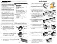
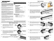
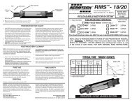
RMS 29/40-120 Assembly and Operation <strong>Instructions</strong>BEFORE YOU BEGIN:*****Study the illustrations and sequence of assembly. THESEQUENCE OF ASSEMBLY IS EXTREMELY IMPOR-TANT. USE RMS MOTORS AND RELOAD KITSONLY IN ACCORDANCE WITH ALL INSTRUCTIONS.Review the parts list and become familiar with all partsbefore assembly. IF ANY PARTS ARE MISSING ORDAMAGED, CONTACT RCS AT 1 (435) 865-7100 oremail at: warranty@aerotech-rocketry.comDO NOT USE ANY PART OF THE RMS SYSTEMTHAT ARE DAMAGED IN ANY WAY. If in doubt, contactRCS at the number above for assistance.DO NOT MODIFY THE MOTOR IN ANY WAY. Modificationof the motor or the reload kit parts could result inmotor failure, lead to the destruction of both your rocketand motor and may cause personal injury, death and/orproperty damage. Modification of the motor or reload kitin any way will invalidate your motor warranty.USE ONLY <strong>AeroTech</strong>/RCS RMS RELOAD KITSAND MOTOR PARTS TO REFURBISH YOUR RMSMOTOR. The <strong>AeroTech</strong>/RCS reload kits havebeen designed specifically for use in your particular<strong>AeroTech</strong>/RCS RMS Motor. Use of imitation componentsmay destroy your motor, rocket and payload andwill invalidate your motor warranty. Only use <strong>AeroTech</strong>/RCS RMS reload kits intended for your specific<strong>AeroTech</strong>/RCS RMS motor. DO NOT INTER-CHANGE PARTS! Do not use <strong>AeroTech</strong>/RCS RMSreload kits or motor components for any other purposethan to refurbish an <strong>AeroTech</strong>/RCS motor.DO NOT REUSE ANY OF THE DISPOSABLE PARTSOF THE RMS RELOAD KIT. This includes theliner, nozzle and o-rings. These components have beendesigned for one use only and must be discarded afterfiring. Reuse can result in motor failure during subsequentoperation and invalidate your motor warranty.*Motors are hot after firing. Although the RMS operates ata lower temperature than most disposable motors, the higherthermal conductivity of the aluminum motor parts may make itseem otherwise. If necessary to handle a motor before it hascooled down, use a rag or similar article.Read and follow the safety codes of the National Associationof Rocketry (NAR) and the Tripoli Rocketry Association andcomply with all federal, state and local laws in all activitieswith hobby rockets.PARTS:RMS-29/40-120 MOTOR29mm Aft Closure 129mm Case 129mm Forward Closure 1Grease1 tubeRELOAD KITLiner (1” O.D. tube) 1Propellant Grain (long slotted part) 1Grain Adapter (7/8” O.D. tube) 0 or 1Delay Grain (short solid part) 1Delay Spacer (9/16” O.D. washer or tube) 0 or 1Delay Insulator (5/8” O.D. tube) 1Delay O-Ring (5/8” O.D. x 3/32” thick) 1Forward Insulator (1” O.D. washer) 1Aft O-Ring (1/16” thick x 1” O.D.) 1Forward O-Ring (1/16” thick x 1” O.D.) 1Nozzle (Black plastic part) 1COPPERHEAD Igniter 1Ejection Charge Container/Nozzle Cap 1ITEMS NEEDED FOR USE:Wet wipes or damp paper towelsHobby knife or scissorsMasking tape7.8.9.10.11.12.13.14.WARNING: FAILURE TO INSTALL THE DELAY ASSEMBLYCORRECTLY AS SHOWN MAY RESULT IN THE EJECTIONCHARGE FUNCTIONING AT THE TIME OF IGNITION OFTHE MOTOR, POSSIBLY DAMAGING YOUR MOTOR ANDROCKET.Fig-4: Remove the burr from the inside of the ends of the linertube. Insert the grain adapter tube (if provided) into the linertube until FLUSH with one end of the liner tube.Fig-4: Place a small piece of masking tape over the slot onone end of the propellant grain. (“E & F” reloads only). NOTE:The tape allows the proper positioning of the igniter when it isinstalled. Insert the propellant grain into the liner tube with themasking tape facing the grain adapter tube.Fig-5: Insert the liner assembly into the motor case until it isrecessed equally from both ends of the case. Hold the linerassembly in place with your finger.Fig-5: Place the forward insulator into the case, seated againstthe liner assembly (grain adapter end). Place the greased 1/16”x 1” forward o-ring against the forward insulator as shown.Fig-6: Thread the forward (black) closure into the same end ofthe motor case by hand until it stops against the case.Fig-7: Insert the black coated end of the COPPERHEADigniter into the slot in the propellant grain until it stops againstthe tape on the end of the propellant grain (“E & F” reloads).Fig-8: Using the point of a pencil, remove any plastic “flashing”that may still remain in the nozzle throat. Insert the nozzle intothe open end of the motor case, with the igniter lead threadedthrough the nozzle throat, until the nozzle is in liner tube andseated against the propellant grain.Fig-9: Place the greased aft o-ring (1/16” thick) into the groovebetween the nozzle and case.Fig-4Propellant Grain, Tapeon This SideFig-5Fig-6Fig-7Fig-8Liner AssyForward InsulatorCaseLiner TubeGrain AdapterGreased 1/16”Forward O-RingInstall ForwardClosure on ThisEnd of CaseIgniter SeatedAgainstTape on PropellantInstall Nozzle OverIgniter Until SeatedAgainst PropellantGrain in Liner1.2.3.4.5.6.Apply a light coat of grease to the 3 O-rings and allthreaded surfaces. This will facilitate assembly and preventthe threads from siezing. NOTE: When all thegrease that comes with the motor has been consumed,use petroleum jelly or similar grease.Using your fingernail or a blunt object, remove the burr(rough raised edge) from both inside and outside endsof the delay insulator tube by pressing or scraping androtating the tube at the same time.Fig-1: If supplied with the reload kit, press the delayspacer into one end of the delay insulator tube untilFLUSH with the end of the tube.Fig-1: Press the delay element into the other end ofthe delay insulator tube until it is FLUSH with the otherend of the tube.Fig-2: Place the greased 5/8” O.D. x 3/32” thick o-ringin the forward closure, seated against the forward endof the delay cavity.Fig-3: Insert the delay charge/delay insulator assemblyinto the delay cavity until it is seated against the delayo-ringDelay Spacer(if provided)Fig-1Fig-2Delay AssemblyDelay ChargeAssembly ProtudesApprox.1/16”Fig-3Delay Insulator (deburred)Delay ElementForwardClosureGreased3/32” x 5/8”DelayO-RingForward ClosureWithDelay ElementFacingO-Ring as Shown15.16.17.Fig-10: Thread the aft (gold) closure into the motor by handuntil it stops against the end of the case. A rag or paper towelmay be used to get a better grip on the closure.Fig-11: Hold the ejection charge container/nozzle cap assemblywith the nozzle cap (the wider plastic cap) pointing up.CAREFULLY remove the nozzle cap from the ejection chargecontainer. Holding the motor in a vertical position with theFORWARD (black) closure pointing down, snap the ejectioncharge container over the matching end of the FORWARDclosure. WARNING: DO NOT LOOSEN THE FORWARDCLOSURE ONCE THE EJECTION CHARGE CONTAINERHAS BEEN SNAPPED INTO POSITION. Loosening the forwardclosure will cause ejection charge to leak under theforward o-ring and may lead to seal failure.With the motor held in a NOZZLE DOWN position, gentlyshake the motor several times to settle the ejection charge intothe delay cavity above the delay element.NOTE: If it becomes necessary to remove the AFT (gold)closure to replace the igniter due to misfire, hold the motor in anozzle-up position and avoid moving the liner assembly in thecase during the operation.Fig-9Fig-10Fig-11Install Greased Aft1/16” O-Ring inGrooveBetween Nozzleand Case.Thread Aft Closureinto Case UntilSeatedAgainst CaseInstall Ejection ChargeContainer onto ForwardClosure Held as Shown