ER-5684 -- USP Joist Hangers, Truss Hangers ... - USP Connectors
ER-5684 -- USP Joist Hangers, Truss Hangers ... - USP Connectors
ER-5684 -- USP Joist Hangers, Truss Hangers ... - USP Connectors

You also want an ePaper? Increase the reach of your titles
YUMPU automatically turns print PDFs into web optimized ePapers that Google loves.
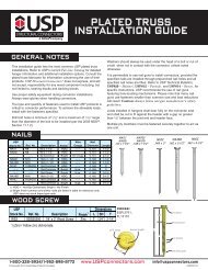
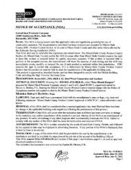
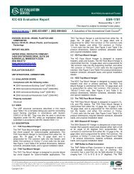
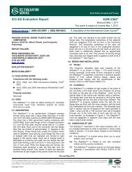
<strong>ER</strong>-<strong>5684</strong>Reissued November 1, 2002ICBO Evaluation Service, Inc. • 5360 Workman Mill Road, Whittier, California 90601 • www.icboes.orgFiling Category: FASTEN<strong>ER</strong>S—Wood <strong>Hangers</strong> and Framing Anchors<strong>USP</strong> JOIST HANG<strong>ER</strong>S, TRUSS HANG<strong>ER</strong>S, ADJUSTABL<strong>ER</strong>AFT<strong>ER</strong> CONNECTORS AND SELF-ADJUSTINGBEARING CLIPSUNITED STEEL PRODUCTS COMPANY703 ROG<strong>ER</strong>S DRIVEMONTGOM<strong>ER</strong>Y, MINNESOTA 560691.0 SUBJECT<strong>USP</strong> <strong>Joist</strong> <strong>Hangers</strong>, <strong>Truss</strong> <strong>Hangers</strong>, Adjustable Rafter<strong>Connectors</strong> and Self-adjusting Bearing Clips.2.0 DESCRIPTION2.1 THF Face Mount <strong>Hangers</strong>:THF series joist hangers are U-shaped connectors used tosupport I-joists and laminated veneer lumber (LVL)members of various widths from 1 1 / 2inches to 5 1 / 4inches(38 to 133 mm). The minimum width of the supportingwood member is 1 3 / 4inches (44.5 mm). THF hangers have2-inch- and 2 1 / 2-inch-deep (51 and 63.5 mm) seats withwidths varying from 1 1 / 2inches to 5 3 / 8inches (38 to 136.5mm), and varying heights. Figure 1 and Table 1 shownailing schedules, dimensions and allowable loads.2.2 HD Face Mount <strong>Hangers</strong>:HD series joist hangers are U-shaped connectors used tosupport wood members of various widths from 1 1 / 2inchesto 5 1 / 2inches (38 to 140 mm). The minimum width of thesupporting wood member is 1 15 / 16inches (49 mm). The HDhangers have 2-inch- and 2 1 / 2-inch-deep (51 mm and 63.5mm) seats with widths varying from 1 9 / 16inches to 5 1 / 2inches (39 mm to 140 mm), and varying heights. Figure 2and Table 2 show nail schedules, dimensions andallowable loads.2.3 THO Top Mount I-<strong>Joist</strong> <strong>Hangers</strong>:THO series joist hangers are U-shaped connectors used tosupport wood I-joists of various flange widths from 1 1 / 2inches (38 mm) to 4 3 / 4inches (121 mm). The minimumwidth of the supporting wood member is 1 3 / 4inches (44.5mm) where the 10d common × 1 1 / 2-inch-long (38 mm) nailsare prescribed, and 1 15 / 16inches (49 mm) where 16dcommon nails are prescribed. The THO hangers have 2-,2 3 / 8-, and 3-inch-deep (51, 60 or 76 mm) seats and varyingheights. Seat widths vary from 1 9 / 16inches (40 mm) to 4 3 / 4inches (121 mm). The 2-inch- and 2 3 / 8-inch-deep (51 mmand 60 mm) hangers have double ribs on each top flange,and some 2 3 / 8-inch-deep (60 mm) hangers have anadditional rib in the seat area. Figure 3 and Table 3 shownail schedules, dimensions and allowable loads.2.4 HHDO Top Mount <strong>Hangers</strong>:HHDO series joist hangers are U-shaped connectors usedto support wood members of various widths from 3 inches(76 mm) to 5 1 / 2inches (140 mm). The minimum width ofthe supporting wood member is 3 inches (76 mm). TheHHDO hangers have 2 1 / 2-, 3-, and 3 1 / 2-inch-deep (63.5, 76and 89 mm) seats, and varying heights. Seat widths varyfrom 3 1 / 8inches to 5 9 / 16inches (79 mm to 141 mm). NA20Dnails are supplied with the hangers. Figure 4 and Table 4show nail schedules, dimensions and allowable loads.2.5 HDO Top Mount <strong>Hangers</strong>:HDO series joist hangers are U-shaped connectors used tosupport wood members of various widths from 1 1 / 2inchesto 7 inches (38 to 178 mm). The minimum width of thesupporting wood members is 1 15 / 16inches (49 mm). TheHDO hangers have 2-, 2 1 / 2-, 3- and 3 1 / 2-inch-deep (51,63.5, 76 and 89 mm) seats, with varying heights. <strong>Hangers</strong>with 2-inch-deep (51 mm) seats have seat widths of 5 9 / 16inches (141 mm), hangers with 2 1 / 2-inch-deep (63.5 mm)seats have seat widths varying from 1 9 / 16inches (40 mm) to7 1 / 8inches (181 mm), and hangers with 3-inch- and 3 1 / 2-inch-deep (76 mm and 89 mm) seats have seat widthsvarying from 1 9 / 16inches (40 mm) to 4 11 / 16inches (119 mm).Figure 5 and Table 5 show nail schedules, dimensions andallowable loads.2.6 THD Face Mount <strong>Truss</strong> <strong>Hangers</strong>:THD series hangers are U-shaped joist hangers used tosupport 1 1 / 2-inch-wide (51 mm) wood trusses or 1 3 / 4-inchwide(44.5 mm) LVL. The minimum width of supportingwood elements is 1 15 / 16inches (49 mm). The THD trusshangers have 3-inch-deep (76 mm) seats, 1 5 / 8inches (41mm) and 1 7 / 8to 3 5 / 8inches (48 to 92 mm) wide, and varyingheights. Figure 6 and Table 6 show nail schedules,dimensions and allowable loads.2.7 SKH Skewed <strong>Joist</strong> <strong>Hangers</strong>:SKH series hangers are U-shaped joist hangers used tosupport wood members such as wood I-joists and lumberjoists in various widths from 1 1 / 2inches to 3 inches (38 to76 mm). The minimum width of the supporting woodmembers is 1 3 / 4inches (44.5 mm) where 10d common nailsare specified and 1 15 / 16inches (49 mm) where 16d commonnails are specified. The skew of the wood member is to bein the range of 40 to 50 degrees. SKH hangers have 1 7 / 8-inch-deep (48 mm) seats, and varying heights. Seat widthsvary from 1 9 / 16inches (40 mm) to 3 9 / 16inches (90.5 mm).SKH hangers have oversized nail holes on the 45-degreeside, to allow angled nailing. Figure 7 and Table 7 shownail schedules, dimensions and allowable loads.are not to be construed as representing aesthetics or any other attributes not specifically addressed, nor are they to be construed asan endorsement of the subject of the report or a recommendation for its use. There is no warranty by ICBO Evaluation Service, Inc., express or implied,as to any finding or other matter in this report, or as to any product covered by the report.Copyright © 2001 Page 1 of 13
Page 2 of 13 <strong>ER</strong>-<strong>5684</strong>2.8 TMU Adjustable Rafter <strong>Connectors</strong>:TMU series connectors are adjustable rafter connectors forroof slopes from a positive slope of 8:12 (67%) to anegative slope of 12:12 (100%). The minimum width of thesupporting header is 1 3 / 4inches (44.5 mm). The seat depthis 3 1 / 2inches (89 mm), except for the TMU-48, which has aseat depth of 3 3 / 8inches (86 mm). The seat widths varyfrom 1 9 / 16inches (40 mm) to 3 9 / 16inches (90.5 mm), withvarying heights. The nail holes located on the vertical rafterportion of the connector are provided with raised “dimples”so as to toenail the rafter to the header. Figure 8 and Table8 show nailing schedules, dimensions and allowable loads.2.9 TMP Self-adjusting Bearing Clips:TMP series connectors are used to connect rafters to walltop plates and are fabricated from No. 18 gage galvanizedsteel. The clips adjust from a minimum roof slope of 1:12(8.33%) to a maximum roof slope of 6:12 (50%). Figure 9and Table 9 show nail schedules, dimensions andallowable loads.2.10 Materials:2.10.1 Steel: The THO15950, THO15118, THO17950 andTHO17118 and THD28-2, THD 210-2, THD48, THD410,and THD412 connectors are fabricated from galvanizedsteel complying with ASTM A 653 CS, with a zinc coatingdesignation of G60, a minimum yield of 28,000 psi (192MPa) and a minimum tensile strength of 38,000 psi (267MPa). All other connectors listed herein are fabricated fromgalvanized steel complying with ASTM A 653 SS Grade 33,with a zinc coating designation of G60, a minimum yieldstrength of 33,000 psi (228 MPa) and a minimum tensilestrength of 45,000 psi (310 MPa). Minimum base-metalthickness for No. 12 gage is 0.0994 inch (2.5 mm), for No.14 gage is 0.0705 inch (1.8 mm), for No. 16 gage is 0.0575inch (1.5 mm) and for No. 18 gage is 0.0466 inch (1.2 mm).2.10.2 Wood: The wood elements shall have dimensionsconsistent with the connector dimensions stated in Tables1 through 9. The allowable design values are based onlumber having a specific minimum gravity of 0.50, such asDouglas fir–larch, with moisture content not exceeding 19percent. Wood-based materials that are recognized fordesign properties equivalent to values stated in thisevaluation report may be substituted.The following are the minimum widths of the supportingwood elements for each connector series, and the requirednail size when pertinent: THF, 1 3 / 4inches (44.5 mm); HD,1 15 / 16inches (49 mm); THO, 1 3 / 4inches (44.5 mm) for 10dcommon nails and 1 15 / 16inches (49 mm) for 16d commonnails; HHDO, 2 3 / 8inches (60 mm); HDO, 1 15 / 16inches (49mm); THD, 1 15 / 16inches (49 mm); SKH 2, 1 3 / 4inches (44.5mm) for 10d common nails and 1 15 / 16inches (49 mm) for16d common nails.2.10.3 Fasteners: Common wire nails shall comply withASTM F 1667, except that the HA20D nail is a 2 1 / 2-inchlong(63.5 mm) 20d common nail, the 10d × 1 1 / 2nail is a10d common nail that is 1 1 / 2inches (38 mm) long, and the8d × 1 1 / 2nail is an 8d common nail that is 1 1 / 2inches (38mm) long. The 8d × 1 1 / 2nail shall have a minimum bendingyield strength of 100,000 psi (689 MPa). The 10d, 16d, and10d × 1 1 / 2nails shall have a minimum bending yieldstrength, F yb, of 90,000 psi (236 MPa). The 20d andHA20D nail shall have a minimum bending yield strength,F yb, of 80,000 psi (209 MPa). If galvanized nails are used,the coatings must meet ASTM A 641 Class 1 requirements.2.11 Torsional Moments:For the HD, THO, HDO, HHDO, SKH, TMU, THD and THFSeries connectors intended for various joist sizes, endblocking is not required.For the TMP Series connectors, blocking specified inSection 4.4.1.2 of ANSI/NFoPA NDS-1991 is required forthe connected members.2.12 Design:Tabulated allowable design loads for the connectors arebased on the lowest load obtained from comparing:• The least test load that causes 1 / 8inch (3.2 mm)deflection.• The lowest ultimate test load with a safety factor of 3.• Allowable fastener values and compressionperpendicular-to-grain values in accordance with Chapter23 of the 1997 Uniform Building Code (UBC), based onwood with a minimum specific gravity of 0.50The lowest value determined from the above criteria,except for the bearing capacities, has been adjusted for aduration of load up to the maximum resisted load.The connected wood member shall be designed for theapplied loads. The design calculations shall be submittedto and approved by the building official. Allowable valuesfor the connections described in this report are forconnectors installed in wood seasoned to a moisturecontent of 19 percent or less, and used under continuouslydry conditions and subjected to sustained temperatures of100°F (37.7°C) or less. For connections in wood that isunseasoned or partially seasoned, or when connections areexposed to wet-surface condition in use, the allowableloads in this report must be multiplied by the moisturecontent factor, C m, specified in ANSI/NFoPA NDS-1991.2.13 Installation:Installation shall comply with the manufacturer’s publishedinstallation instructions, this report and the UBC. Copies ofthe instructions shall be available at all times on the jobsiteduring installation.2.14 Identification:Each of the United Steel Products Company devicesdescribed in this report shall be identified by a stamp orlabel bearing the manufacturer’s name and/or <strong>USP</strong> ®trademark, the model number and the evaluation reportnumber (ICBO ES <strong>ER</strong>-<strong>5684</strong>).3.0 EVIDENCE SUBMITTEDData in accordance with the ICBO ES Acceptance Criteriafor <strong>Joist</strong> <strong>Hangers</strong> and Similar Devices (AC13), datedJanuary 2002.4.0 FINDINGSThat the <strong>USP</strong> Lumber <strong>Connectors</strong> described in thisreport comply with the 1997 Uniform Building Code(UBC), subject to the following conditions:4.1 The devices are manufactured, identified andinstalled in accordance with this report and themanufacturer’s installation instructions.4.2 The maximum allowable load is determined byusing the values in Tables 1 through 9 with theappropriate duration of load adjustment.
Page 3 of 13 <strong>ER</strong>-<strong>5684</strong>4.3 Allowable values listed in this report are forconnections in wood seasoned to a moisturecontent of 19 percent or less that are used undercontinuously dry conditions and sustainedtemperatures of 100°F (37.7°C) or less.4.4 For connections in wood that is unseasoned orpartially seasoned, or when connections areexposed to wet-service conditions in use, theallowable loads in this report are multiplied by themoisture content factor, C m, specified by the UBC.4.5 The scope of this evaluation is limited toconnectors which are installed on lumber orequivalent wood-based material that has not beentreated with fire-retardant or pressure-treatmentchemicals.4.6 All plans specifying connectors listed in thisreport shall be accompanied by calculationsdemonstrating that the allowable loads containedin this report are not exceeded. Thesecalculations shall be subject to approval by thebuilding official.4.7 The connectors are manufactured by the UnitedSteel Products Company at their facilities locatedin Livermore, California; and Montgomery,Minnesota.This report is subject to re-examination in two years.
Page 4 of 13 <strong>ER</strong>-<strong>5684</strong>
Page 5 of 13 <strong>ER</strong>-<strong>5684</strong>
Page 6 of 13 <strong>ER</strong>-<strong>5684</strong>
Page 7 of 13 <strong>ER</strong>-<strong>5684</strong>
Page 8 of 13 <strong>ER</strong>-<strong>5684</strong>
Page 9 of 13 <strong>ER</strong>-<strong>5684</strong>
Page 10 of 13<strong>ER</strong>-<strong>5684</strong>
Page 11 of 13<strong>ER</strong>-<strong>5684</strong>
Page 12 of 13<strong>ER</strong>-<strong>5684</strong>THF S<strong>ER</strong>IESFIGURE 1HD S<strong>ER</strong>IESFIGURE 2THO S<strong>ER</strong>IESFIGURE 3HHDO S<strong>ER</strong>IESFIGURE 4HDO S<strong>ER</strong>IESFIGURE 5
Page 13 of 13<strong>ER</strong>-<strong>5684</strong>THD S<strong>ER</strong>IESFIGURE 6SKH S<strong>ER</strong>IESFIGURE 7TMU S<strong>ER</strong>IESFIGURE 8TMP S<strong>ER</strong>IESFIGURE 9*THESE DRAWINGS ARE FOR ILLUSTRATION PURPOSES ONLY. THEY ARE NOT INTENDED FOR USE AS CONSTRUCTIONDOCUMENTS FOR THE PURPOSE OF FABRICATION OR <strong>ER</strong>ECTION.