data sheet - COMEVAL
data sheet - COMEVAL
data sheet - COMEVAL
- No tags were found...

You also want an ePaper? Increase the reach of your titles
YUMPU automatically turns print PDFs into web optimized ePapers that Google loves.
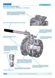
Wafer Swing Check ValvesDesign Attributes4 In line Centring Eye Bolt; to ease the contractorcommissioning and maintenance operations.5 Marking and Identification; riveted ontothe body side, in line visible, indication of DN,PN, service permissible conditions, materialsand approval.1 High Safety Hinges, extrareinforced to ensure the flap despitethe flow strikes.2 Resilient seal raised face;ensuring atmospheric tightness andsaves installing sealing.3 Polished plate and chromedplate body; abrasion proof andresistant to severe environmentalduties.E Identification Plate; riveted inthe body side.D Vulcanised body seats;ensuring the bubble tightnessseating even with suspendedsolids particles in the flow.C Nickel plated plates; surface treatmentto improve the abrasion resistance to fluids.B Wafer design body; ruggedand ease to install; allows lighthandling even in large sizeswithout diminishing the industrialcompactness.A Integral flange facingseals; made out of EPDM, firmlybonded to the flange face side,ensuring the atmospherictightness while saving installingadditional flange sealing kits.Engineering Construction DataSingle Swing Check ValvesStandard Design Pressure PN 25, other design ratings such as PN 40 or ANSI Class on request * Uni directional valve design *Reduced Bore flow (see charts) * Standard face to Face length API 6D * Nominal Diametres larger than 24” (DN 600) as per MSS-SP-44 * Other lengths on request * Wafer Design to install between flanges DIN 2576 PN 10, DIN 2502 PN 16 as standard; other counterflange assembly on request*Dual Plate Check ValvesStandard Design Pressure PN 16, other design ratings such as PN 40 or ANSI Class on request * Uni directional valve design * FullBore flow (see charts) * Minimal Pressure Drop * Standard face to Face length DIN 3202 K5 (EN 558-1) * Other lengths on request* Wafer Design to install between flanges DIN 2576 PN 10 * Outside Diametre suitable to install between other counter flangeassembly (i.e: ANSI B16.5) on request.(1).- All measuring units used in the elaboration of this <strong>data</strong><strong>sheet</strong> unless otherwise stated are: Dimensions in mm / Weights in Kgs / Kvs in m3/h / Pressure in barg (1 barg = 0.1 Mpa).(2).- Information regarding the installation, start up and maintenance of equipment can be obtained from the Tech.Dept. and/or the Quality Technical Department.
Wafer Single Flap Swing Check ValvesCV-CC-E CV-CI-E CV-II-E CV-BB-EDimensionsDNmm pulg. PN6 PN10 PN16 PN25 PN40Parts and Bill of MaterialsA B C* D WEIGHT Min ∆PUNI 2223 ANSI B16.5 PN6-PN25 PN40ANSI150Body Flap Material Sealing Material Product CodeChromed Plated Carbon St. Chromed Plated Carbon St. EPDM CV-CC-EChromed Plated Carbon St. Stainless Steel 316 EPDM CV-CI-EStainless Steel 316 Stainless Steel 316 EPDM CV-II-EAluminium Bronze Aluminium Bronze EPDM CV-BB-EOptional Designs and MaterialsANSI300ANSI 15040 1 1/2" 88 94 94 94 94 87 95 23 14 14 76,7 0,7 0,0106550 2" 98 109 109 109 109 105 111 33 14 14 86,4 0,9 0,006665 2 1/2" 118 129 129 129 129 124 130 41 14 14 106,4 1,2 0,003880 3" 134 144 144 144 144 137 149 54 14 14 118,4 1,5 0,00283100 4" 154 164 164 170 170 175 181 71 18 18 114,4 2,5 0,0032125 5" 184 194 194 198 198 197 216 92 18 18 173,4 3,3 0,0024150 6" 209 220 220 228 228 222 251 112 20 20 197,4 4,7 0,00241200 8" 264 275 275 288 293 279 308 155 22 27 254,4 7,8 0,00168250 10" 319 330 334 343 355 340 362 201 26 33 306,4 13 0,00179300 12" 375 380 389 403 420 410 422 240 32 41 357,6 19 0,00179350 14" 425 440 449 460 477 451 485 270 38 46 408,6 34 0,00287400 16" 474 493 498 517 549 514 540 311 44 52 456,6 46 0,00284450 18" 529 543 558 567 574 549 597 361 50 57 498,6 63 0,00305500 20" 579 598 620 627 631 606 654 405 56 68 550,6 88 0,0036600 24" 683 698 737 734 716** 486 62 665 128 0,00336700 28" 788 813 807 836 832** 575 68 745 195 0,0035800 32" 893 920 914 945 940** 670 80 868,6 281 0,00359900 36" 993 1.020 1.014 1.045 1.048** 755 86 958 372 0,003761000 40" 1.093 1.127 1.130 1.158 1.162** 848 96 1.058 487 0,00372Bill of Materials used for the manufacture of the single flap check valves are diverse, the extended use of stainless steel is not expensivethanks to the valve light design. Standard valve sealing is EPDM, on request other elastomeric compounds or metal seated valves aresupplied.The chart below shows the standard material combination and codes:The following indicated suffixes denote the sealing valve material:B=BUNA N; V=VITON*; T= PTFE; M=METAL - VITON is a registered Trade Mark of DUPONT NEMOURS.Observe the elastomeric temperature Design limitations:BUNA N = 110ºC; VITON= 160ºC ; PTFE=200ºC; METAL= 400ºCA number of options can be manufactured on request depending on their construction design.Materials:All PTFE made valves (Code CT-TT-T); BUNA N coated flap material (Code CN-CB-B), polished mirror stainless steel material for hygienicduties; Exotic materials such as MONEL, HASTELLOY B, HASTELLOY C, TITANIUM…Spring loaded Valve designs:Valves supplied with spring loaded plate on request. The desired opening pressure must be indicated in the requirement.Manufacture length:DIN 3202 K4, DIN 3202 K5 (new designation EN 558-1)ANSI300Kg***bar***(1).- All measuring units used in the elaboration of this <strong>data</strong><strong>sheet</strong> unless otherwise stated are: Dimensions in mm / Weights in Kgs / Kvs in m3/h / Pressure in barg (1 barg = 0.1 Mpa).(2).- Information regarding the installation, start up and maintenance of equipment can be obtained from the Tech.Dept. and/or the Quality Technical Department.
Wafer Single Flap Swing Check ValvesPressure Drop DiagramNote(1).- All measuring units used in the elaboration of this <strong>data</strong><strong>sheet</strong> unless otherwise stated are: Dimensions in mm / Weights in Kgs / Kvs in m3/h / Pressure in barg (1 barg = 0.1 Mpa).(2).- Information regarding the installation, start up and maintenance of equipment can be obtained from the Tech.Dept. and/or the Quality Technical Department.
Wafer Single Flap Swing Check ValvesOpening PressuresSingle Flap Check Valves can be installed either horizontally or vertically with flow pressurised according to the arrow direction. Thecharts below are stating the opening pressures, expressed in mBar and according tot he flow direction and the valve design beingspring loaded or without spring.No spring Valves (standard Design)DN 40 50 65 80 100 125 150 200 250 300∆p 9 9 7 7 6 6 8 11 10 11∆p 0 0 0 0 0 0 0 0 0 0(pressure Units expressed in mbar)Spring loaded ValvesDN 50 65 80 100 125 150 200 250 300∆p 17 15 15 14 14 16 19 18 19∆p 8 8 8 8 8 8 8 8 8(pressure Units expressed in mbar)Installation InstructionsSome installations guidelines are below described as a quickreference to the General Installation Booklets provided alongwith the valve supplies.- Horizontal Installation is always preferred as and when bepossible. (valve axis in the upper side)- The valve should be installed with the disc opening fromdownwards to upwards according to the pressurised side of thepump impulsion.- No external centring rings are required for the standard PN 10valves.- Allow for a free lifting of the flap, do not block the full lift withassembling kits.- Spring loaded valves are recommended when the opening needsto be restricted as per flow pressure.- A minimum installation distance of at least 5 to 10 times theValve DN in mm is to be allowed between the pressure pumpand the valve.5 -10 x DN ValveMain ApplicationsWafer Check valves are generally recommended for those applications where the service pressure is notcritical and where weight and installation space be a major factor. Please observe material compatibility andconsult your application engineer; in case of doubt, contact your usual supplier of UNI CHECK valves.Temperature rate to be considered in terms of elastomeric seating choice.Water * Waste Water * Sewage Systems * Oil * Process * Gases(1).- All measuring units used in the elaboration of this <strong>data</strong><strong>sheet</strong> unless otherwise stated are: Dimensions in mm / Weights in Kgs / Kvs in m3/h / Pressure in barg (1 barg = 0.1 Mpa).(2).- Information regarding the installation, start up and maintenance of equipment can be obtained from the Tech.Dept. and/or the Quality Technical Department.