Models M610 and M610-2E - Shure
Models M610 and M610-2E - Shure
Models M610 and M610-2E - Shure
- No tags were found...

You also want an ePaper? Increase the reach of your titles
YUMPU automatically turns print PDFs into web optimized ePapers that Google loves.
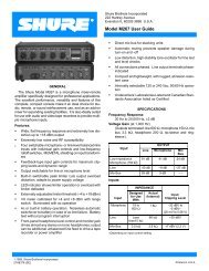
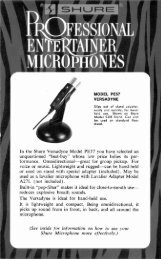
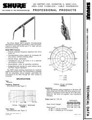
OVERALL DIMENSIONS - FIGURE 1Phase: the "live" or "hot" terminal of the plug, <strong>and</strong> thePin 3 of the Microphone lnput is in phase with pin 3 of blue lead to the neutral terminal of the plug. Thethe Microphone Output <strong>and</strong> out of phase with the tip of green/yellow lead is the grounding conductor <strong>and</strong>Aux. Output <strong>and</strong> the tip of the Aux. Input.should be connected to the ground or earth terminalFilter Characteristics:of the plug.Moving Filter Frequency control from 0 to 12 reduces Before connecting the <strong>M610</strong>-<strong>2E</strong> to the power source,gain by 12 d~ t 2 ,j~ at frequency of maximum attenua- the line voltage selector slide switch on the rear paneltion. This center frequency is within -+20% of nominal (Item 22 of Figure 3) must be set to the proper posifrequency.One octave from center frequency, moving tion- To change the selector switch to the 108-132Filter Frequency control from 0 to 12 reduces gain by V.A.C. position, loosen the mounting screw holding3.5 dB t 1 dB.the switch locking tab until the tab can be rotatedaway from the switch lever. Tighten the mountingBelow 63 switch: 6 dB per octave slope, 9 dB downscrew <strong>and</strong> set the switch as(+2 dB) at 20 Hz.Above 8K switch: 6 dB per octave slope, 8 dB downCONTROLS AND CONNECTORS(+2 dB) at 20 kHz. See Figure 3.Typical filter frequency response characteristics are Inputs:shown in Figures 4 <strong>and</strong> 5. Filters are electrically iso- Microphone:lated for minimum phase interaction.The microphone input (16), located on the rear panelOperating Voltage:<strong>and</strong> designated Mic. Input, is designed for low-impe-AC Operation: dance (balanced or unbalanced) microphones with 25<strong>M610</strong>: 108-132 volts, 50/60 Hz, 3 watts to 600 ohms impedance or high-impedance (unbalanced)dynamic, ribbon, or condenser microphones. The unit is<strong>M610</strong>-<strong>2E</strong>: 108-132 Or 216-264 50/60 Hz, not recommended for use with crystal or ceramic microasselected by a switch On the phones. The impedance is selected by a slide switchrear panel.(17) above the Mic. lnput receptacle. The input recep-DC Operation: 30 volts * 20% at approximately tacle is a professional three-pin audio connector (fe-12 mA.male).* Figure 2 refers to microphone connections. SeeTemperature Range:Figure 2 for low- <strong>and</strong> high-impedance connections toOperating: -7°C to 57°C (20°F to 135°F)receptacle.Storage: -29°C to 7I0C(-20°F to 160°F)Note: Some condenser microphones produce very highNet Weight: 1.8 kg (3 Ib, 15 oz) output signals which may overload the input. UsePackaged Weight: 2.4 kg (5 Ib, 4 oz)of an attenuator (such as the <strong>Shure</strong> A15A In-LineMicrophone Attenuator) will improve this situa-Dimensions:tion.See Figure 1.'Designed to mate with Cannon XL series. Switchcraft A3 (Q.G.) series orINSTALLATIONequivalent connector. [<strong>Shure</strong> part 95A407 (male) or 95A548 (female).]WARNINGTo reduce the risk of fire or electric shock, do notexpose this appliance to rain or extreme moisture.Auxiliary:The Aux. lnput phono pin jack (15) on the rear panelhas a built-in switch that disables the Mic. lnput preamplifierwhen a phono plug is inserted.The Aux. lnput will accept output from a high-impedance,high-level source, such as a mixer, audioconsole, tape recorder, MVl-FM tuner, or phonographpreamplifier.Outputs:The <strong>M610</strong> or <strong>M610</strong>-<strong>2E</strong> is typically connected in theauxiliary, high-level line between the preamplifier/mixer <strong>and</strong> the power amplifier, or between the microphone<strong>and</strong> the preamplifier/mixer in single-micro- The receptacle marked Mic. Output (18) is a dual-imphonesystems. Any combination of inputs <strong>and</strong> out- pedance output, either low impedance balanced or highputsavailable may be used, however, according to impedance unbalanced, as selected by the switch (19)the particular needs of the user.above the receptacle. The receptacle is a professionalThe Model <strong>M610</strong>-<strong>2E</strong> is supplied with a three-con- three-pin audio connector (male).* See Figure 2 forductor power-line cord, but no plug. The power-line output receptacle connections.cord plug should be installed by qualified service The phono pin jack marked Aux. Output (20) is a highpersonnel.The brown lead should be connected to impedance, high-level output designed primarily to feed
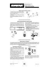
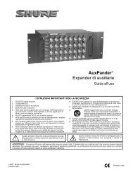
MICROPHONE MIC. INPUT MICROPHONE MIC. INPUTLOW IMPEDANCEHIGH IMPEDANCE(BALANCED LINE1MICROPHONE INPUT PLUG CONNECTIONSMIC. OUTPUTMIC. OUTPUTLOW IMPEDANCEHIGH IMPEDANCE(BPLANCED LINE)MICROPHONE OUTPUT PLUG CONNECTIONSMICROPHONE CONNECTIONS - FIGURE 2u FRONT PANEL u7~610-ZE ONLY)MU\ / \ / REAR PANEL /CONTROLS AND CONNECTORS - FIGURE 3a power amplifier or auxiliary input requiring 0.1 to 2volts.Accessory 30 Volts D.C.:These rear panel jacks (21) provide 30 volts dc foraccessories such as the A68M Microphone Preamplifier.The jacks are also used as a power input whenusing the Model A67B Battery Power Supply (Accessory).These jacks provide 34 Vdc open circuit (30 Vdcat 6 mA max.).Controls (See Figure 3):Power Switch <strong>and</strong> Pilot Light:The power On-Off switch (14) controls operation ofthe unit when it is powered either by the ac line or byan external dc source. The pilot light (13) indicatesoperation only when ac power is used.Filter Frequency Controls:The eight linear motion Filter Frequency controls (2)-(9) located on the front panel are used for adjusting thelevel of eight octave-spaced b<strong>and</strong>s having center frequenciesof 63 Hz, 125 Hz, 250 Hz, 500 Hz, 1 kHz, 2 kHz,4 kHz, <strong>and</strong> 8 kHz respectively. The levels of the octavespacedb<strong>and</strong>s are individually <strong>and</strong> continuously adjustablefrom flat at full up position to approximately 12 dBcut at full down position. Figures 4-1 <strong>and</strong> 4-2 illustratethe frequency response characteristic of each octavefilter when adjust& for 6 dB cut <strong>and</strong> full cut.Below 63 <strong>and</strong> Above 8K Switches:The Below 63 filter slide switch (1) reduces the gainof frequencies below the 63 Hz octave b<strong>and</strong> when placedin the down position, <strong>and</strong> the Above 8K filter slideswitch (10) reduces the gain of frequencies above the8 kHz octave b<strong>and</strong> when placed in the down position.Figure 5 shows the frequency response characteristicsof these filters.Mode (Filter-Bypass) Switch:In the Bypass position, the Mode switch (11) disablesthe filters <strong>and</strong> the Filter Level control <strong>and</strong> sets gain fromAux. lnput to Aux. Output, or Mic. lnput to Mic. Output,at approximately unity. The filters <strong>and</strong> Filter Level controlare operative in the Filter position.Filter Level Control:The Filter Level control (12) provides up to 24 dB gainwhen filters are enabled, as well as gain reduction belowunity. The Filter Level control is used to increase systemgain as filters are adjusted. A setting of 4 for this controlwill provide approximately unity gain through theController in the Filter mode.
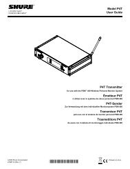
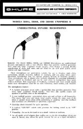
Wm*g01000 l0,oOO 20,000FREQUENCY (HZ)FIGURE 4-1 -EACH FILTER AT 6 dB ATTENUATION:-10Y2 -15 L I2 4 6 8 1 2 4 6 8 1 2 4 6 8 1 2J 20 100 1000 lO.000 eopooEFIGURE 4-2-FREQUENCY (HZ)EACH FILTER AT MAXIMUM ATTENUATIONINDIVIDUAL OCTAVE FILTER FREQUENCYCHARACTERISTIC (TYPICAL)FIGURE 4OPERATION1. Connect line cord to ac power source or use A67BBattery Power Supply.Set panel controls as follows:On-Off slide switch (14) to ON position.Mode slide switch (11) to BYPASS position.Below 63 (1) <strong>and</strong> Above 8K (10) slide switch toflat (up) position.All eight Filter Frequency controls (2)-(9) to full upposition.Filter Level control (12) to zero (fully counterclockwise).2. Adjust the amplifier gain of the sound system (usingthe preamplifier/mixer or power amplifier volumecontrol) until feedback becomes apparent. Reducethe gain setting until it is comfortably belowthe feedback level.3. Set Mode slide switch (11) to FILTER position. IncreaseFilter Level control (12) until feedbacksqueal or ringing is heard.4. If the feedback sound is high pitched, one of thefour high-frequency Filter Frequency controls (1kHz through 8 kHz) (6)-(9) will be most effectivein eliminating the feedback. Individually move eachFilter Frequency control slowly from top to bottom<strong>and</strong> back to top while listening for feedback. Thecontrol which eliminates feedback with the leastmotion should then be moved down only so far asnecessary to eliminate the feedback.5. If the feedback frequency happens to fall betweenthe b<strong>and</strong>s covered by two adjacent controls, then itmay be necessary to move down both controls toobtain the desired feedback suppression.6. If the feedback sound first noted in step 4 is of alow frequency, then the adjustment procedureshould be started using the low-frequency (63 Hzthrough 500 Hz) Filter Frequency controls (2)-(5).7. Having eliminated the first feedback condition, increasethe gain of the sound system with theFilter Level control (12) until feedback is againnoted. Repeat the procedures of the precedingsteps 3 through 6 to eliminate the new feedbackcondition. This may require adjustment of a differentFilter Frequency control or may require afurther decrease in the control or controls previouslymoved down.8. Repeat step 7 until either (A), one or more FilterFrequency controls has been set to maximum attenuation,or (B), feedback appears to occur at morethan one frequency simultaneously. Do not reducethe setting of any Filter Frequency controls morethan necessary to stop ringing or squealing duringthe above procedure.9. Conduct a talk test through the sound system withthe Mode switch set to FILTER <strong>and</strong> listen forringing. If ringing is noted, attempt to eliminate itby a slight decrease in the setting of the Filter Levelcontrol or further decrease in the appropriate FilterFrequency control setting.10. During the above procedure, it will not usually benecessary to set either the Below 63 or Above 8Kswitches to the down position to eliminate feedbackunless the pitch of the feedback is extremely lowor extremely high. These switches are primarily intendedfor improving overall sound quality or tonalbalance, if necessary. After feedback has beeneliminated as outlined above, actuate each switch<strong>and</strong> note the tonal character of the system duringthe talk test. It will usually be advantageous to actuatethe Below 63 switch if the 63 Hz Filter Frequencycontrol is set below 6, <strong>and</strong> to actuate theAbove 8K switch if the 8 kHz Filter Frequency controlis set below 6.650"7 W02, -5W-''2 4 6 8 1 2 4 6 0 1 2 4 6 8 1 2$ 20 100 1000 lop00 20,000_IFREQUENCY (HZ)W LLBELOW 63 AND ABOVE 8K FILTER FREQUENCY CHARACTERISTICS(TYPICAL)FIGURE 5WARNINGVoltages in this equipment are hazardous to life.Refer servicing to qualified service personnel.OPTIONAL ACCESSORIESLocking Panel ....................... .Model A68LRack Panel Kit ...................... .Model A68RGUARANTEEThis <strong>Shure</strong> product is guaranteed in normal use tobe free from electrical <strong>and</strong> mechanioal defects for aperiod of one year from date of purchase. Pleaseretain proof of purchase date. This guarantee includesall parts <strong>and</strong> labor. This guarantee is in lieu of any<strong>and</strong> all other guarantees or warranties, express orimplied, <strong>and</strong> there shall be no recovery for any consequentialor incidental damages.SHIPPING INSTRUCTIONSCarefully repack the unit <strong>and</strong> return it prepaid to:<strong>Shure</strong> Brothers IncorporatedAttention: Service Department1501 West <strong>Shure</strong> DriveArlington Heights, Illinois 60004If outside the United States, return the unit to yourdealer or Authorized <strong>Shure</strong> Service Center for repair.The unit will be returned to you prepaid.
BLK.PARTS LISTITEM SHURE PART NO. SHURE KIT NO. QTY. IN KIT DESCRIPTIONDl. D2 86A404 RKC2 I 4 DIODE. SILICON, IN4002 OR EQUIVALENTJ I 95B634 - - PHONO JACK WITH SWITCHJ2 95A482 RKC83 2 INPUT CONNECTORJ3 95A 198 RK122P I OUTPUT CONNECTORJ4 956450 - - PHONO JACKJ5, J6 95A226, 958226 - - D.C. RECEPTACLE, BLACK AND REDK I 90A 1662 RKC6 I KNOBK2-9 90A2044 AND 65A 1239A - - KNOB AND SLEEVEPL I 80A79 RKC45 I NEON PILOT LIGHT ASSEMBLY (RESISTOR INTERNAL)9101, 9103, 0105 86A350 RKC89 4 NPN SILICON TRANSISTOR, HIGH GAIN, LOW NOISE,0107 SIMILAR TO MOTOROLA 2N52109102, 0104, 9106 86A348 - - PNP SILICON TRANSISTOR, HIGH GAIN, LOW NOISE,9108 SIMILAR TO MOTOROLA 2N50870109-Q116 866349 RKC9 4 NPN SILICON TRANSISTOR, HIGH GAIN, LOW NOISE.SIMILAR TO MOTOROLA MPS6521R5 46A02 1 RKC3 I ROTARY POTENTIOMETER, 50K, AUDIO TAPERR6-R13 46A045 - - SLIDE POTENTIOMETER, 250K, AUDIO TAPER51. 52 55A54 RKClO 4 SLIDE SWITCH. DPDT53 558103 - - SLIDE SWITCH, DPDT, 3 AMP.. WITH SOLDER SHIELD54 55A119 - - SLIDE SWITCH, DPDTS5, 56 55883 - - SLIDE SWITCH. DPDl57 55A66 - - SLIDE SWITCH. DPDT. 3 AMP.. WITH SOLDER SHIELDTI, TZ 9082150 - I TRANSFORMER AND SHIELD ASSEMBLYT3 5 1 A255 - - POWER TRANSFORMERF I BOA155 - - FUSE, 1/16 AMP.PARTS PLACEMENT