Operation Manual - Critical Power Supplies
Operation Manual - Critical Power Supplies
Operation Manual - Critical Power Supplies

You also want an ePaper? Increase the reach of your titles
YUMPU automatically turns print PDFs into web optimized ePapers that Google loves.
This manual and the safety guide are available in English on the enclosed CD and the APC Web site, www.apc.com.Uživatelská příručka a bezpečnostní pokyny jsou k dispozici v češtině na přiloženém CD a na webových stránkách APC -www.apc.com.Denne vejledning og sikkerhedsvejledningen er tilgængelige på dansk på den vedlagte CD og på APC's websted, www.apc.com.Dieses Handbuch sowie die Sicherheitsrichtlinien sind in deutscher Sprache auf der beiliegenden CD und auf der Website vonAPC unter www.apc.com verfügbar.Este manual y la guía de seguridad están disponibles en español en el CD adjunto y en el sitio Web de APC, www.apc.com.Ce manuel et le guide de sécurité sont disponibles en français sur le CD-ROM ci-inclus et sur le site Web d'APC, www.apc.com.A használati utasítás és a biztonsági útmutató megtalálható magyarul a csatolt CD-n és az APC honlapján: www.apc.com.Il presente manuale e la corrispondente Guida per la sicurezza sono disponibili in italiano sul CD-ROM allegato e sul sito Webdi APC all'indirizzo www.apc.com.Deze handleiding en het veiligheidshandboek staan in het Nederlands op de bijgevoegde cd en op de APC-website:www.apc.com.En norsk versjon av denne håndboken og sikkerhetsveiledningen finnes på den vedlagte CD-en og på APCs webområdewww.apc.com.Este manual e o guia de segurança estão disponíveis em português no CD incluso e no website da APC, www.apc.com.Instrukcja obsługi oraz przewodnik bezpieczeństwa w języku polskim dostępne są na załączonej płycie CD i na stronieinternetowej APC, www.apc.com.Denna manual och säkerhetsguide finns tillgänglig på svenska på medföljande CD och på APC:s webbsida, www.apc.com.Bu kılavuzun ve güvenlik kılavuzunun Türkçe versiyonu ürünle birlikte verilen CD’de ve www.apc.com adresindeki APC websitesinde bulunmaktadır.Panduan dan petunjuk keselamatan ini tersedia dalam Bahasa Inggris pada CD terlampir dan pada Situs APC, www.apc.com.本 書 及 び 安 全 ガイドの 日 本 語 版 は、 同 梱 の CD 及 び APC の Web サイト(www.apc.com)からご 覧 戴 けます。이 매뉴얼과 안전 가이드는 동봉된 CD 와 APC 웹사이트 www.apc.com 에서 한글로 이용할 수 있습니다 .Англоязычный вариант данного руководства и руководства по технике безопасности имеется на прилагаемомкомпакт-диске, а также на сайте компании APC: www.apc.com.คําแนะนําด้านความปลอดภัยและคู่มือนี้ที่เปนภาษาไทย สามารถดูได้ในซีดีที่ให้มาและเว็บไซต์ของ APC, www.apc.com您 可 以 从 随 附 的 CD 与 APC 网 站 (www.apc.com) 上 获 得 本 手 册 与 安 全 指 南 的 中 文 版 本 。您 可 以 從 隨 附 的 CD 與 APC 網 站 (www.apc.com) 上 獲 得 本 手 冊 與 安 全 指 南 的 中 文 版 本 。Το εγχειρίδιο αυτό και ο οδηγός ασφάλειας είναι διαθέσιμα στα ελληνικά στο CD που εσωκλείεται και στην ιστοσελίδα τηςAPC, www.apc.com.
ContentsOverview . . . . . . . . . . . . . . . . . . . . . . . . . . . . . . . . . . . . . . . . . . . . . . . . 1Inventory . . . . . . . . . . . . . . . . . . . . . . . . . . . . . . . . . . . . . . . . . . . . . . . 1Hardware . . . . . . . . . . . . . . . . . . . . . . . . . . . . . . . . . . . . . . . . . . . . . . . 1Specifications . . . . . . . . . . . . . . . . . . . . . . . . . . . . . . . . . . . . . . . . . . . . 2Environmental Specifications . . . . . . . . . . . . . . . . . . . . . . . . . . . . . . 2Physical Specifications . . . . . . . . . . . . . . . . . . . . . . . . . . . . . . . . . . . 2Installation . . . . . . . . . . . . . . . . . . . . . . . . . . . . . . . . . . . . . . . . . . . . . . . 3Stack or rack-mount front panel . . . . . . . . . . . . . . . . . . . . . . . . . . . . 3<strong>Power</strong>View installation for stack or rack-mount configurations . . 3Stack configuration . . . . . . . . . . . . . . . . . . . . . . . . . . . . . . . . . . . . . . 4Rack-mount configuration . . . . . . . . . . . . . . . . . . . . . . . . . . . . . . . . . 4Install rails in rack . . . . . . . . . . . . . . . . . . . . . . . . . . . . . . . . . . . . . . . 4Mount units in rack . . . . . . . . . . . . . . . . . . . . . . . . . . . . . . . . . . . . . . . 5Route ethernet cable . . . . . . . . . . . . . . . . . . . . . . . . . . . . . . . . . . . . . 6Install bezels . . . . . . . . . . . . . . . . . . . . . . . . . . . . . . . . . . . . . . . . . . . . 7Accessories . . . . . . . . . . . . . . . . . . . . . . . . . . . . . . . . . . . . . . . . . . . . . 7Optional accessories . . . . . . . . . . . . . . . . . . . . . . . . . . . . . . . . . . . . . 7Hardwire the UPS . . . . . . . . . . . . . . . . . . . . . . . . . . . . . . . . . . . . . . . . . 8Install input and output wiring trays in UPS rear panel . . . . . . . . . 9Wiring Specifications . . . . . . . . . . . . . . . . . . . . . . . . . . . . . . . . . . . . 10Input wiring options . . . . . . . . . . . . . . . . . . . . . . . . . . . . . . . . . . . . . 12Output wiring options . . . . . . . . . . . . . . . . . . . . . . . . . . . . . . . . . . . 15<strong>Operation</strong> . . . . . . . . . . . . . . . . . . . . . . . . . . . . . . . . . . . . . . . . . . . . . . . 17Normal operation . . . . . . . . . . . . . . . . . . . . . . . . . . . . . . . . . . . . . . . 17Battery operation . . . . . . . . . . . . . . . . . . . . . . . . . . . . . . . . . . . . . . . 17Bypass operation . . . . . . . . . . . . . . . . . . . . . . . . . . . . . . . . . . . . . . . 17Battery LED . . . . . . . . . . . . . . . . . . . . . . . . . . . . . . . . . . . . . . . . . . . . 17<strong>Power</strong>View Interface Display . . . . . . . . . . . . . . . . . . . . . . . . . . . . . . 17Navigating menu screens . . . . . . . . . . . . . . . . . . . . . . . . . . . . . . . . 18Menu Tree . . . . . . . . . . . . . . . . . . . . . . . . . . . . . . . . . . . . . . . . . . . . . 18Sub menu screens . . . . . . . . . . . . . . . . . . . . . . . . . . . . . . . . . . . . . . 19Start-Up . . . . . . . . . . . . . . . . . . . . . . . . . . . . . . . . . . . . . . . . . . . . . . . . 21Connect load to UPS . . . . . . . . . . . . . . . . . . . . . . . . . . . . . . . . . . . . 21Connect power to UPS and load . . . . . . . . . . . . . . . . . . . . . . . . . . . 21Communication port . . . . . . . . . . . . . . . . . . . . . . . . . . . . . . . . . . . . . 21Emergency <strong>Power</strong> Off (EPO) . . . . . . . . . . . . . . . . . . . . . . . . . . . . . . . 22SURT15k/20k 230 VAC Stack/Rack-Mount 6U XLI/XLICH/XLI-CCi
Troubleshooting Display Messages . . . . . . . . . . . . . . . . . . . . . . . . . 23Maintenance . . . . . . . . . . . . . . . . . . . . . . . . . . . . . . . . . . . . . . . . . . . . 25Replace battery modules . . . . . . . . . . . . . . . . . . . . . . . . . . . . . . . . . 25Service. . . . . . . . . . . . . . . . . . . . . . . . . . . . . . . . . . . . . . . . . . . . . . . . . 26Transport the unit . . . . . . . . . . . . . . . . . . . . . . . . . . . . . . . . . . . . . . . 26Contact Information . . . . . . . . . . . . . . . . . . . . . . . . . . . . . . . . . . . . . . 26Two-Year Warranty. . . . . . . . . . . . . . . . . . . . . . . . . . . . . . . . . . . . . . . 27iiSURT15k/20k 230 VAC Stack/Rack-Mount 6U XLI/XLICH/XLI-CC
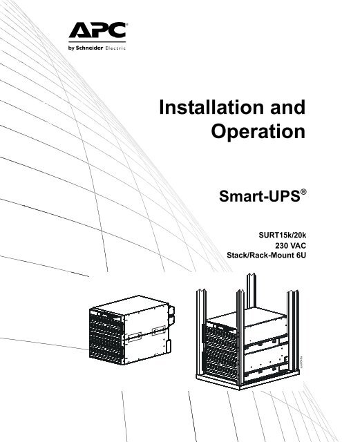
OverviewThe APC ® by Schneider Electric Smart-UPS ® SURT15k/20k Stack/Rack-Mount 6U 230 VAC is a highperformance uninterruptible power supply (UPS). It provides protection for electronic equipment from utilitypower blackouts, brownouts, sags, and surges; small utility fluctuations and large disturbances. The UPS alsoprovides battery backup power until utility power returns to safe levels or the batteries are fully discharged.InventoryThe UPS and the external battery pack (XLBP) are packaged separately.Read the Safety Guide before installing the UPS.Inspect the UPS upon receipt. Notify the carrier and dealer if there is damage.The packaging is recyclable; save it for reuse or dispose of it properly.Check the package contents:• UPS• Input wiring tray• Output wiring tray• <strong>Power</strong>View display module• Front bezel• DB9 serial cable• Ethernet jumper cable for rearpanel network access• Literature kit containing:– Product documentation– Smart-UPS ® RT User <strong>Manual</strong>s CD– Network Management Card Utility CD– Network Management Carddocumentation– Safety information– Warranty information• Rack-mount models also include:– Rail Kit– Four ornamental screws– Two cage nuts– Two rail cleats– Four pan head screws– Two rack-mount brackets– Eight flat head screwsNOTE: The model and serial numbers are located on a small, rear panel label. For some models, an additional labelis located on the chassis under the front bezel.Hardware8 Flat head screws for securing rack-mount or tie brackets to the UPS andXLBP2 rack-mount or tie brackets4 Rack-mount units:pan head screws for securing rail cleats to the UPS2 rail cleats2 Rack-mount units:cage nuts for rack-mount installation4 Rack-mount units:ornamental screws for securing the UPS to the rackSURT15k/20k 230 VAC Stack/Rack-Mount 6U XLI/XLICH/XLI-CC 1
SpecificationsEnvironmental SpecificationsTemperatureOperatingStorageMaximumElevationOperatingStorageHumidity0° to 40° C (32° to 104° F)-15° to 45° C (5° to 113° F)charge the UPS battery every six months30° to 70° C (86° to 158° F)charge the UPS battery every three months3,000 m (10,000 ft)15,240 m (50,000 ft)0 to 95% relative humidity,non-condensingThis unit is intended for indoor use only. Select alocation sturdy enough to handle the weight.Do not operate the UPS where there is excessivedust or the temperature or humidity are outside thespecified limits.This unit has front to rear airflow. Allow adequatespace for proper ventilation.Environmental factors impact battery life. Hightemperatures, poor utility power, and frequent,short duration discharges will shorten battery life.Physical SpecificationsWeightCombined shipping weight UPS and one XL battery packCombined weight (no packing material) UPS and one XL battery pack314.09 kg (691 lb)247.73 kg (545 lb)UPS (no packing material)XL Battery Pack(no packing material)with eight battery modules66 kg (145 lb)181 kg (400 lb)Dimensions482 mm19 in465 mm18.3 in432 mm17 in773 mm30.4 in263 mm10.4 in102 mm4 insuo0642a2SURT15k/20k 230 VAC Stack/Rack-Mount 6U XLI/XLICH/XLI-CC
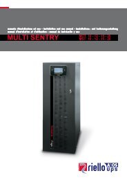
InstallationStack or rack-mount front panel<strong>Power</strong>ViewInterface DisplayRJ45 Connector (pass through to rear panel RJ45 connector)Serial Port<strong>Power</strong>View Cable ConnectorSmartSlot with Network Management CardEthernet port 10/100 Base-TCold Start/EPO Resetsuo0643a<strong>Power</strong>View installation for stack or rack-mount configurationsPrior to attaching the <strong>Power</strong>View to the UPS:1. Loosen the two bracket screws on the back of the <strong>Power</strong>View module.a. Slide the bracket to the position that will accommodate the screw holes on the UPS.b. Tighten the screws on the bracket.2. Secure the <strong>Power</strong>View to the UPS using the two thumb screws attached to the <strong>Power</strong>View.suo0646asuo0645asuo0644aConnect the <strong>Power</strong>View cable to the <strong>Power</strong>View connector on the UPS.SURT15k/20k 230 VAC Stack/Rack-Mount 6U XLI/XLICH/XLI-CC 3
Stack configurationThe UPS and the XLBPs must be connected with ground wires. Refer to the XLBP user manual for details.Always place the UPS above the XLBP(s) in a stackconfiguration.Total stack configuration height is recommended NOT to exceed18U. This is the equivalent of two XLBPs and one UPS.Four screws must be used to secure each tie bracket to the units,(see diagram).For detailed instructions on installing batteries, the batterydoors, refer to the Rack-mount configuration section of thismanual.Refer to the Rack-mount configuration section in this manual forcable routing and bezel installation details.suo0663a8xTie Brackets(included with XLBP)Rack-mount configurationInstall rack-mount bracketsFour flat head screws must be used to secure eachrack-mount bracket to the unit.Install rail cleatsTwo pan head screws must be used to secure each rail cleatto the unit.4xsuo0665asuo0664a2xInstall rails in rackFor details on rail installation refer to the instructions included in the rail kit package.4SURT15k/20k 230 VAC Stack/Rack-Mount 6U XLI/XLICH/XLI-CC
Mount units in rackThe UPS and XLBP should be installed at or near the bottom of the rack. Always place the UPS above theXLBP(s). Batteries must be removed from the XLBP(s) prior to installing the unit(s) in a rack. Refer to theinstructions on the packaging for details on removing the batteries from the XLBP.Install units in racksuo0667aSecure the UPS and the XLBP in the rackusing the cage nuts and ornamental screwsincluded in the package.Four ornamental screws and two cage nutsmust be used to secure each unit.A cage nut must be used in the top hole of eachrack-mount bracket when securing the unit inthe rack.7 holesThe bottom hole of each rack-mount bracketmust be secured using an ornamental screw inthe threaded hole.7 holes4xsuo0666a4xInstall and connect battery modulesConnect all eight battery modules. Failureto do so may cause equipment damage.Replace the battery doors.Tighten the screws to secure the battery doors.suo0669asuo0668aSURT15k/20k 230 VAC Stack/Rack-Mount 6U XLI/XLICH/XLI-CC 5
Route ethernet cableEthernet cable wiring rear panel accessLocate the RJ45 connector and the ethernet port on the front panel of the UPS. Connect the ethernet jumper cable(included), to the RJ45 connector and the ethernet port.Connect a network cable (not included), to the RJ45 connector on the rear panel of the UPS.There is an internal ethernet cable that connects the front and rear panel RJ45 connectors.Ethernet CableEthernet Jumper CableRJ45 Connectorsuo0670aEthernetPortEthernet Cable connected to rearpanel RJ45 connectorInternal pass through ethernet cable connecting front andrear panel RJ45 connectorsEthernet cable wiring front panelCables that are connected to the UPS for front panel access must be routed through one of the notches on the bezel.Ethernet Portsuo0651aEthernet Cable6SURT15k/20k 230 VAC Stack/Rack-Mount 6U XLI/XLICH/XLI-CC
Install bezelsInstall a bezel on the UPS and XLBP(s).suo0650aAccessoriesInstall accessories prior to connecting power to the UPS.• Refer to the APC Web site, www.apc.com for available accessories.• User documentation for the Network Management Card installed on this UPS is available on the Utility CDincluded with this unit.Optional accessories• Maintenance bypass• SURT192RMXLBP2• Equipment cartSURT15k/20k 230 VAC Stack/Rack-Mount 6U XLI/XLICH/XLI-CC 7
Install input and output wiring trays in UPS rear panelInput Wiring TrayRJ45ConnectorXLBP ConnectorOutput Wiring TrayGroundEPO PortCold Start/EPO ResetGroundsuo0649aInput Wiring Traysuo0673aOutput Wiring TraySURT15k/20k 230 VAC Stack/Rack-Mount 6U XLI/XLICH/XLI-CC 9
Wiring SpecificationsAdhere to national and local electrical codes when wiring.Input ConnectionsOutput ConnectionsMain InputSingle-Phase: Wire to L1, N, andHardwireSingle-Phase: Wire to L1, N, andThree-Phase: Wire to L1, L2, L3, N, andThree-Phase: Wire to L1, L2, L3, N, andBypass Input (optional)Single-Phase: Wire to B1, N, andSingle-phase PDUXL battery pack PDU to UPS: Wire L1, N,Three-Phase: Wire to B1, B2, B3, N, andSingle FeedWiringNumberofPhasesVoltageCurrentFull Load***(maximum)External InputCircuit Breaker(typical)Wire Size(typical)*SURT15K XLI/XLICH/XLI-CCInputOutput11220/230/240 VAC220/230/240 VAC83 A66 A100 A each phasenot required35 mm 225 mm 2InputOutput31380/400/415 VAC220/230/240 VAC28 A each phase66 A100 A each phase**not required35 mm 2**25 mm 2InputOutput33380/400/415 VAC380/400/415 VAC28 A each phase22 A each phase35 A or 40 A each phasenot required6 mm 26 mm 2SURT20K XLI/XLICH/XLI-CCInputOutput11220/230/240 VAC220/230/240 VAC105 A87 A125 A each phasenot required50 mm 235 mm 2InputOutput31380/400/415 VAC220/230/240 VAC35 A each phase87 A125 A each phase**not required50 mm 2**35 mm 2InputOutput33380/400/415 VAC380/400/415 VAC35 A each phase29 A each phase50 A each phasenot required10 mm 210 mm 2*Terminal screw tightening torque: 4.5 Nm (40 lb-in) minimum**Use cables and input circuit breakers rated for specifications listed in these tables.NOTE: Units configured for three phase input and single phase output operation, the entire load connected to theUPS will transfer to L1 and Neutral of the three phase input when the UPS is operating in Bypass mode.***The current is specified at nominal input voltage.The acceptable input frequency range is 40 Hz to 70 Hz.The output frequency is user selectable. Refer to the <strong>Power</strong>View display menu screens for available options.10SURT15k/20k 230 VAC Stack/Rack-Mount 6U XLI/XLICH/XLI-CC
Dual FeedWiringNumberofPhasesVoltageCurrentFull Load***(maximum)External InputCircuit BreakerMains (typical)External InputCircuit BreakerBypass (typical)WireSizeMains*(typical)WireSizeBypass*(typical)SURT15K XLI/XLICH/XLI-CCInputOutput11220/230/240 VAC220/230/240 VAC83 A66 A100 A each phasenot required100 A each phasenot required35 mm 2 35 mm 225 mm 2 25 mm 2InputOutput31380/400/415 VAC220/230/240 VAC28 A each phase66 A35 A or 40 A each phasenot required100 A each phase**not required6 mm 2 35 mm 2**25 mm 2 25 mm 2InputOutput33380/400/415 VAC380/400/415 VAC28 A each phase22 A each phase35 A or 40 A each phasenot required35 A or 40 A each phasenot required6 mm 2 6 mm 26 mm 2 6 mm 2SURT20K XLI/XLICH/XLI-CCInputOutput11220/230/240 VAC220/230/240 VAC105 A87 A125 A each phasenot required125 A each phasenot required50 mm 2 50 mm 235 mm 2 35 mm 2InputOutput31380/400/415 VAC220/230/240 VAC35 A each phase87 A50 A each phasenot required125 A each phase**not required10 mm 2 50 mm 2**35 mm 2 35 mm 2InputOutput33380/400/415 VAC380/400/415 VAC35 A each phase29 A each phase50 A each phasenot required50 A each phasenot required10 mm 2 10 mm 210 mm 2 10 mm 2*Terminal screw tightening torque: 4.5 Nm (40 lb-in) minimum**Use cables and input circuit breakers rated for specifications listed in these tables.NOTE: Units configured for three phase input and single phase output operation, the entire load connected to theUPS will transfer to L1 and Neutral of the three phase input when the UPS is operating in Bypass mode.***The current is specified at nominal input voltage.The acceptable input frequency range is 40 Hz to 70 Hz.The output frequency is user selectable. Refer to the <strong>Power</strong>View display menu screens for available optionsSURT15k/20k 230 VAC Stack/Rack-Mount 6U XLI/XLICH/XLI-CC 11
Input wiring optionsInput wiring overview: Refer to the diagrams on the following pages for input wiring options.Main Input <strong>Power</strong> Single and ThreeBypass Input <strong>Power</strong> Single and ThreeMain Phase 1 Bypass Phase 1Main Phase 2Bypass Phase 2Main Phase 3NeutralBypass Phase 3GroundGND NEUL3L2L1B1B2B3MSJSJ1SJ2BSJLabeled jumpers must beinstalled in the appropriatelocations.SJ3suo0675aInput/Output Jumper ConfigurationsInputJumpersOutputJumpers<strong>Power</strong> I/O ConfigurationInput:OutputSeparateBypass Feed SJ1 SJ2 SJ3 MSJ BSJ OSJ1:1** No * *1:1 Yes3:1 No3:1 Yes3:3 No3:3 Yes* Optional** Factory DefaultI12SURT15k/20k 230 VAC Stack/Rack-Mount 6U XLI/XLICH/XLI-CC
Input wiring option 3Three phase input, single phase output,single feedInput wiring option 4Three phase input, single phase output,dual feedGNDNEU L3L2L1B1B2B3GNDNEU L3L2L1B1B2B3SJ1BSJBSJsuo0679aGNDNEU L3L2L1B1B2B3suo6781asuo0678aInput wiring option 5Three phase input, three phase output,single feedInput wiring option 6Three phase input, three phase output, dualfeedGNDNEU L3L2L1B1B2B3SJ1SJ2SJ3suo0680a14SURT15k/20k 230 VAC Stack/Rack-Mount 6U XLI/XLICH/XLI-CC
Output wiring optionsOutput wiring overview. Refer to the diagrams on the following pages for output wiring options.Labeled jumpers and connectors must be installed in the appropriate locations.Output Phase 3NeutralGroundOutput Phase 2Output Phase 1NL3 L2 L1OSJFactory Default ConfigurationOutput Shorting Jumper (OSJ)for single phase outputPDU Terminalssuo0682aOutput hardwire option 1Single phase hardwire outputconnectionOutput hardwire option 2Three phase hardwire output connectionXLBP PDU not connectedOutput shorting jumper (OSJ) removedNL3 L2 L1OSJEnsure the OSJ issecured to the outputwiring tray using thefive screws provided.NL3 L2 L1suo0683asuo0684aSURT15k/20k 230 VAC Stack/Rack-Mount 6U XLI/XLICH/XLI-CC 15
Output PDU optionSingle phase output connection to battery pack PDUNL3 L2 L1OSJEnsure the OSJ is secured to the output wiring tray using thefive screws provided.PDU connectorssuo0685aXLBP16SURT15k/20k 230 VAC Stack/Rack-Mount 6U XLI/XLICH/XLI-CC
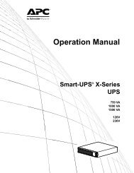
<strong>Operation</strong>The UPS has three operation mode options.Normal operationDuring normal operation, the UPS double converts utility power to conditioned power for the connected load.Battery operationDuring battery operation, the UPS provides power to the connected load from batteries for a finite period of time.The UPS transfers to battery operation if the supply of utility power fails or is outside predefined limits.Bypass operationBypass mode is reached either as a user selection or automatically.• Bypass mode can be selected through the Control menu screen on the <strong>Power</strong>View display• The UPS will automatically switch into bypass mode if:– Both normal and battery operation modes are unavailable– An output overload condition occurs– The UPS has an internal faultDuring bypass operation the utility power is connected to the load, bypassing the internal converters. If bypassmode becomes unavailable the UPS will automatically switch to mains power. In the event that mains power isunavailable the system will switch to battery power.Battery LEDThe battery LED is located on the front bezel of the XLBP. During normal operation the LED is not illuminated.On start-up the XLBP LED may illuminate and blink within the first minute. The LED should then extinquish.Refer to the XLBP User <strong>Manual</strong> for details on XLBP operation.<strong>Power</strong>View Interface DisplayThe four LEDs to the left of the LCD displayindicate the operational status of the UPS.The five navigation keys to the right of the LCDdisplay are used to select and open menu items, toaccess information, change system parameters, andto access context-sensitive help.Chrg 000%Load 000%000Vin 000Vout 0Hz1:1Runtime:00hr0msu0162bLOAD ON When LED illuminates green, the UPS supplies power to the loadON BATT When LED illuminates yellow, power to load flows from the batteries to the power moduleBYPASS When LED illuminates yellow, power to the load is supplied through bypassFAULT When LED illuminates red, a fault condition existsLCD Screen Displays menu screens for alarms, status data, instructional help, and configuration itemsUP and DOWNnavigation keysUsed to scroll through and select menu itemsHELP key Opens context-sensitive helpENTER key Opens menu items and saves changes to system parametersESC key Returns to previous screen displayedSURT15k/20k 230 VAC Stack/Rack-Mount 6U XLI/XLICH/XLI-CC 17
Navigating menu screensUse the ESC key to navigate between menu screens.Use the UP/DOWN arrow keys to scroll through the list of sub menus and commands on any screen.arrow indicates that there are sub menus containing user selectable commands.Use the ENTER keyTo access the overview status screen on the LCD pressthe ESC key.to navigate to a sub menu and to select user configurable commands.Chrg XXX%Load XXX%XXXVin XXXVout XHz1:1Runtime:XXhrXmsu0193aTo access the main menu screen from the overviewstatus screen, press the ENTER key.ControlStatusSetupBatteriesLoggingDisplayDiagsHelpsu0194aMain Menu ScreenFrom the main menu screen it is possible to command, configure, and monitor the system using the sub menu screens:Control, Status, Setup, Logging, Display, Diags and Help (refer to Sub menu screens section in this manual).Use the UP/DOWN arrow keys to select the menu tobe accessed.Press the ENTER key to open a sub menu screen.ControlStatusSetupBatteriesLoggingDisplayDiagsHelpsu0197aMenu TreeThe menu tree provides an overview of thetop level menu screens.Navigating sub menu screensUse the UP/DOWN arrow keys to scrollthrough the list of functions and commandson a sub menu screen.A after the last entry on a sub menu,indicates a continuation of the function/command list.Use the UP/DOWN arrow keys to view theremaining entries in the list.Use the ENTER key to select a commandand move to sub menus associated with thatfunction/command.Overview StatusScreenMain MenuScreenChrg 000%Load 000%000Vin 000Vout 0Hz1:1Runtime:00hr0mControlStatusSetupBatteriesLoggingDisplayDiagsHelpControl Status Setup BatteriesLogging Display DiagsHelpsu0206a18SURT15k/20k 230 VAC Stack/Rack-Mount 6U XLI/XLICH/XLI-CC
Sub menu screensControlStatusSetupBatteriesLoggingDisplayDiagsHelpControlStatusSetupBatteriesLoggingDisplayDiagsHelpUPS into BypassDo Self TestSimulate <strong>Power</strong> FailStart Runtime CalTurn Load OffControlStatusSetupBatteriesSettings:ShutdownDefaultSystemsu0199aLoggingDisplayDiagsHelpAlarmsClockOther123123Vin Vbyp Vout123Iin Ibyp IoutkWkVAFrequenciesMainsBypassOutputLoadBat VoltageBat ChargeRuntimeBat AmpHrUPS TempShutdownDefaultSystemLow Batt DurShutdown DlyTurn On DlyReturn Bat CapSet all UPS settingsto Factory DefaultsNO, ABORTYES, Set to DefaultsVoltageFrequencyFrq. Range1 Phase Mains OnSlew RateCyclic ChrgAuto StartOutput Frequency Options: Auto Sensing; 50 Hz; 60 Hz50 Hz frequency range: 50±3 Hz; 50±0.1 Hz60 Hz frequency range: 60±3 Hz; 60±0.1 HzAlarm ThresholdsLoadRuntimesu0200aAlarmsClockAlarm ThresholdsLoadRuntimeDateTimeClock: The date and time functions are used to time-stamp events in theevent log. To avoid inaccuracies, change the time setting to reflect day lightsaving time where applicable.OtherOther SettingsSelf TestUPS IDExt Bat Capsu0201aExt Bat Cap: Press. Use the UP/DOWN arrow keys to select thedesired value. Press to move to the next digit. Press afterselecting the final value, to lock in the battery capacity setting.SURT15k/20k 230 VAC Stack/Rack-Mount 6U XLI/XLICH/XLI-CC 19
The <strong>Power</strong>View will reference XLBP configuration in the following manner.ControlStatusSetupBatteriesGlobal Bat StatusPack Status/MfgBatPair Status/MfgLoggingDisplayDiagsHelpExternal Battery PackBattPair_1BattPair_2Module_1 Module_2 Module_3 Module_4BattPair_3BattPair_4Module_5 Module_6 Module_7 Module_8GlobalBat Status+/-BatV+/-BatIMax Bat TempCharge+Runtime:-Runtime:BattPair 1BattPair 2Pack Status/Mfg(with LED flashingon selected frame)+/-BatPair+/-BadPacksBadAPC BatteryDiagnosticsBattPair 3 BattPair 4suo0661aBattPair StatusAPC BatteryDiagnosticsFirmware RevisionMfgDateSer#Model#APC BatteryDiagnosticsAPC BatteryDiagnosticssu0202aView LogClear LogControlStatusSetupBatteriesLogging MenuView LogClear LogView StatisticsLoggingDisplayDiagsHelpTime and Event oflast 100 entriesConfirm Clear LogYes, Clear LogNo, AbortViewStatisticsxxx Transfers->Bat.xxx Transfers->byp.xxxxxhr. Inv. Timexxxhr xxmin on Batsu0203aControlStatusSetupBatteriesLoggingDisplayDiagsHelpControlStatusSetupBatteriesLoggingDisplayDiagsHelpDisplay SetupLanguageContrastBeeper SetupFault & DiagnosticsSystem InformationRaw Status DataBeeper SetupBeep atVolumeKey Clicksu0204aFault &DiagnosticsSystemInformationRaw StatusDataNo Active alarmsSystem InformationFW-revisionSNUPS SizeRaw Status DataM states =su0205a20SURT15k/20k 230 VAC Stack/Rack-Mount 6U XLI/XLICH/XLI-CC
Start-UpConnect load to UPS1. The UPS features chassis ground connection screws located on the rear panel, for connecting the groundleads on transient voltage devices.Prior to connecting the grounding cable, ensure that the UPS is NOT connected to utility or batterypower.2. Connect equipment to the UPS.NOTE: This UPS is equipped with an external battery connector on the rear panel of the unit.3. The battery charges to 90% capacity during the first three hours of normal operation. Do not expect fullbattery run capability during this initial charge period.4. Refer to the APC Web site, www.apc.com for battery runtimes.5. Where appropriate use an APC extension battery cable. For ordering details contact your dealer or APCthrough the Web site www.apc.com.6. Add optional accessories to the SmartSlot located on the front panel.For optimal computer system security, install <strong>Power</strong>Chute Smart-UPS monitoring software.Connect power to UPS and load1. Connect input power to the UPS.2. Check the <strong>Power</strong>View interface display for messages.3. Turn on the load using the interface display menu.Communication portSerial Port Use only the supplied cable to connect to the serial port. A standard serial interface cable isincompatible with the UPS.The serial port can be used to configure that Network Management Card.SURT15k/20k 230 VAC Stack/Rack-Mount 6U XLI/XLICH/XLI-CC 21
Emergency <strong>Power</strong> Off (EPO)The output power can be disabled in an emergency by closing a switch connected to the EPO.Adhere to national and local electrical codes when wiring.The switch should be connected in a normally open switch contact. External voltage is not required; the switch isdriven by 12 V internal supply. In closed condition, 2 mA of current are drawn.The EPO switch is internally powered by the UPS for use with non-powered switch circuit breakers.The EPO circuit is considered a Class 2 circuit, (UL, CSA standards) and an SELV circuit (IEC standard).EPO PORT(located on rear panel)EPOConnectorStrip the insulation from one end of each wire to be used for connecting the EPO.Insert a screwdriver into the slot above the terminal to be wired. Insert the stripped wire into theterminal. Remove the screwdriver to secure the wire in the terminal. Repeat for each terminal.su0158aBoth Class 2 and SELV circuits must be isolated from all primary circuitry. Do not connect any circuit to the EPOterminal block unless it can be confirmed that the circuit is Class 2 or SELV. If circuit standard cannot beconfirmed, use a contact closure switch.Use one of the following cable types to connect the UPS to the EPO switch.• CL2: Class 2 cable for general use.• CL2P: Plenum cable for use in ducts, plenums, and other spaces used for environmental air.• CL2R: Riser cable for use in a vertical run in a floor-to-floor shaft.• CLEX: Limited use cable for use in dwellings and for use in raceways.• For installation in Canada: Use only CSA certified, type ELC, (extra-low voltage control cable).• For installation in other countries: Use standard low-voltage cable in accordance with national and localregulations.22SURT15k/20k 230 VAC Stack/Rack-Mount 6U XLI/XLICH/XLI-CC
Troubleshooting Display MessagesUse the table below to solve minor installation and operation problems. Refer to the APC Web site, www.apc.comfor assistance with complex UPS problems.The <strong>Power</strong>View reports various messages on the display, includingalarm status and changes in system configuration. This section lists all the <strong>Power</strong>View display messages, the reasonfor the message, and the appropriate corrective action.Messages may occur simultaneously. If this happens, be sure to review all of the messages for a betterunderstanding of the system condition.Condition<strong>Power</strong>View DisplayMessage Reason for Message Corrective ActionStart-Up#Batteries changed sincelast ON.At least one battery module has beenadded or removed from the UPS since thelast time the Pwr ON command wasissued.No corrective action necessary. Proceedwith the start-up.Automatic Self TestStarted.The UPS has started pre-programmedbattery test.Batt capacity less thanReturn Batt Cap.The battery capacity of the UPS is lessthan the user-specified minimum batterycapacity required to turn on the load.Option 1) Abort the start-up andallow batteries to recharge.Option 2) Continue start-up, with lessthan minimum battery capacity.System Start-UpConfiguration Failed.System configuration error: Start-updiagnostic fault.Check for other alarms.If the problem persists contact APCCustomer Support. Refer to ContactInformation in this manual.Mains: Site Wiring FaultInput and Output Jumpers are notconfigured correctlyCheck input wiring tray jumpers andoutput shorting jumper for compatibility.Refer to the Input/Output JumperConfigurations table in this manual.Bypass Not Available -Wrong Ph SeqCheck bypass jumpers in input wiringtray and output shorting jumper forcompatibility. Check bypass phases forpositive sequence. Refer to the Input/Output Jumper Configurations table inthis manual.Bypass: Site Wiring FaultCheck bypass jumpers in input wiringtray and output shorting jumper forcompatibility. Refer to the Input/OutputJumper Configurations table in thismanual.General Status # of batteries increased. At least one battery pair has been addedto the system.No corrective action is necessary.# of batteries decreased. At least one battery pair has beenremoved from the system.# External Battery Packsincreased.# External Battery Packsdecreased.At least one external battery pack hasbeen connected to the UPS.At least one external battery pack hasbeen disconnected from the UPS.Module Failure Bad Battery Pair. A battery pair has failed and requiresreplacement.Refer to battery pair installation in theexternal battery pack user manual.SURT15k/20k 230 VAC Stack/Rack-Mount 6U XLI/XLICH/XLI-CC 23
Condition<strong>Power</strong>View DisplayMessage Reason for Message Corrective ActionThresholdAlarmLoad <strong>Power</strong> Is AboveAlarm Limit.The load has exceeded the user- specifiedload alarm threshold.Option 1) Use the display interface toraise the alarm threshold.Option 2) Reduce the loadLoad Is No Longer AboveAlarm Threshold.The load exceeded the alarm threshold.The situation has been corrected. Eitherbecause the load decreased or thethreshold was increased.No corrective action is necessary.Min Runtime Restored.The system runtime dropped below theconfigured minimum and has beenrestored:1) Additional battery modules wereinstalled.2) The existing battery modules wererecharged.3) The load was reduced.4) The user- specified threshold wasdecreased.General Fault Need Bat Replacement. One or more battery pairs are in need ofreplacement.Refer to battery installation procedure.No Batteries AreConnected.Discharged Battery.Low- Battery.Weak Batt(s) Detected.Reduced Runtime.Batt Temperature ExceededUpper Limit.Battery Over-VoltageWarning.Runtime Is Below AlarmThreshold.Shutdown Due To LowBattery.Bypass Not Available InputFreq/Volt out Of Range.Mains Not Available. InputFrq/Volt Out of Range.Emergency PSU Fault.No battery power is available.The UPS is on battery operation and thebattery charge is low.The UPS is on battery operation and thebattery charge is low.One or more weak battery pairs detected(only applicable for internal batterymodules).The temperature of one or more batterypacks has exceeded systemspecifications.The battery voltage is too high and thecharger has been deactivated.The predicted runtime is lower than theuser-specified minimum runtime alarmthreshold. Either the battery capacity hasdecreased, or the load has increased.The UPS shutdown while on batteryoperation.The frequency or voltage is out ofacceptable range for bypass. Thismessage occurs when the UPS is online.The frequency or voltage is out ofacceptable range for normal operation.Redundant Emergency <strong>Power</strong> SupplyUnit (PSU) is not working. Internaldiagnostic fault. The UPS will continue tooperate normally.Check that batteries are installed andconnected properly.Shut down the system and the load orrestore the incoming voltage.Replace the weak battery pairs.Contact APC Customer Support. Referto Contact Information in this manual.Option 1) Allow the batteries torecharge.Option 2) If possible, increase thenumber of battery modules.Option 3) Reduce the load.Option 4) Decrease the alarm threshold.No corrective action is necessary.Note: Should this situation reoccur,consider increasing battery capacity.Correct the input voltage to acceptablefrequency or voltage.Contact APC Customer Support. Referto Contact Information in this manual.24SURT15k/20k 230 VAC Stack/Rack-Mount 6U XLI/XLICH/XLI-CC
Condition<strong>Power</strong>View DisplayMessage Reason for Message Corrective ActionGeneral Fault Fan Fault A fan has failed. Contact APC Customer Support. Referto Contact Information in this manual.Static Bypass Switch Fault. The static bypass switch has failed.System Failure Detected bySurveillance.System Not Synchronizedto Bypass.UPS In Bypass Due ToFault.UPS In Bypass Due ToOverload.UPS Is Overloaded.The system has detected an internal error.System cannot synchronize to bypassmode.Bypass mode may be unavailable.The UPS has transferred to bypass modedue to a fault.The load has exceeded the powercapacity.The load has exceeded the system powercapacity.Check for other alarms.If the problem persists contact APCCustomer Support. Refer to ContactInformation in this manual.Option 1) Decrease input frequencysensitivity.Contact APC Customer Support. Referto Contact Information in this manual.Option 2) Correct bypass input voltageto provide acceptable frequency orvoltage.Contact APC Customer Support. Referto Contact Information in this manual.Decrease the load.Option 1) Decrease the load.Option 2) Check the load distribution onthe three phases through the <strong>Power</strong>Viewdisplay. If the load is unevenlydistributed, adjust the load distribution.MaintenanceReplace battery modulesThis UPS has easy-to-replace, hot-swappable battery modules. Replacement is a safe procedure, isolated fromelectrical hazards. You may leave the UPS and connected equipment on during the replacement procedure.Once the batteries are disconnected the connected equipment is not protected from power outages.Refer to the appropriate replacement battery user manual for battery module installation instructions. See yourdealer or contact APC at www.apc.com for information on replacement battery modules.Be sure to deliver the spent battery(s) to a recycling facility or ship it to APC in the replacementbattery packing material.SURT15k/20k 230 VAC Stack/Rack-Mount 6U XLI/XLICH/XLI-CC 25
ServiceIf the unit requires service, do not return it to the dealer. Follow these steps:1. Review the Troubleshooting section of the manual to eliminate common problems.2. If the problem persists, contact APC Customer Support through the APC Web site, www.apc.com.a. Note the model number and serial number and the date of purchase. The model and serialnumbers are located on the rear panel of the unit and are available through the LCD displayon select models.b. Call APC Customer Support and a technician will attempt to solve the problem over thephone. If this is not possible, the technician will issue a Returned Material AuthorizationNumber (RMA#).c. If the unit is under warranty, the repairs are free.d. Service procedures and returns may vary internationally. Refer to the APC Web site forcountry specific instructions.3. Pack the unit in its original packaging. If this is not available, refer to www.apc.com to obtain a new set.a. Pack the unit properly to avoid damage in transit. Never use foam beads for packaging.Damage sustained in transit is not covered under warranty.b. For the UPS, always DISCONNECT THE BATTERY before shipping in compliancewith U.S. Department of Transportation (DOT) and IATA regulations. The batterymay remain in the unit.c. Internal batteries may remain connected in the XLBP during shipment, (if applicable, notall units have XLBPs).4. Write the RMA# provided by Customer Support on the outside of the package.5. Return the unit by insured, pre-paid carrier to the address provided by Customer Support.Transport the unit1. Shut down and disconnect all connected equipment.2. Disconnect the unit from utility power.3. Disconnect all internal and external batteries (if applicable).4. Follow the shipping instructions outlined in the Service section of this manual.Contact InformationCustomer support for this or any other APC product is available at no charge in any of the following ways:• Refer to the APC Web site to access documents in the APC Knowledge Base and to submit customersupport requests.– www.apc.com (Corporate Headquarters)Connect to localized APC Web sites for specific countries, each of which provides customer supportinformation.– www.apc.com/support/Global support searching APC Knowledge Base and using e-support.• Contact an APC Customer Support center by telephone (888) 272-2782.Local, country-specific centers:go to www.apc.com/support/contact for information.Contact the APC representative or other distributor from whom you purchased your APC product for informationon how to obtain local customer support26SURT15k/20k 230 VAC Stack/Rack-Mount 6U XLI/XLICH/XLI-CC
Two-Year WarrantyThe limited warranty provided by American <strong>Power</strong> Conversion (APC ® ) in this statement of Limited Factory Warranty applies only to products youpurchase for your commercial or industrial use in the ordinary course of your business.Terms of warrantyAPC warrants its products to be free from defects in materials and workmanship for a period of two years from the date of purchase. The obligation ofAPC under this warranty is limited to repairing or replacing, at its sole discretion, any such defective products. This warranty does not apply toequipment that has been damaged by accident, negligence or misapplication or has been altered or modified in any way. Repair or replacement of adefective product or part thereof does not extend the original warranty period. Any parts furnished under this warranty may be new or factoryremanufactured.Non-transferable warrantyThis warranty extends only to the original purchaser who must have properly registered the product. The product may be registered at the APC Web site,www.apc.com.ExclusionsAPC shall not be liable under the warranty if its testing and examination disclose that the alleged defect in the product does not exist or was caused byend user or any third person misuse, negligence, improper installation or testing. Further, APC shall not be liable under the warranty for unauthorizedattempts to repair or modify wrong or inadequate electrical voltage or connection, inappropriate on-site operation conditions, corrosive atmosphere,repair, installation, start-up by non-APC designated personnel, a change in location or operating use, exposure to the elements, Acts of God, fire, theft, orinstallation contrary to APC recommendations or specifications or in any event if the APC serial number has been altered, defaced, or removed, or anyother cause beyond the range of the intended use.THERE ARE NO WARRANTIES, EXPRESS OR IMPLIED, BY OPERATION OF LAW OR OTHERWISE, OF PRODUCTS SOLD, SERVICED ORFURNISHED UNDER THIS AGREEMENT OR IN CONNECTION HEREWITH. APC DISCLAIMS ALL IMPLIED WARRANTIES OFMERCHANTABILITY, SATISFACTION AND FITNESS FOR A PARTICULAR PURPOSE. APC EXPRESS WARRANTIES WILL NOT BEENLARGED, DIMINISHED, OR AFFECTED BY AND NO OBLIGATION OR LIABILITY WILL ARISE OUT OF, APC RENDERING OFTECHNICAL OR OTHER ADVICE OR SERVICE IN CONNECTION WITH THE PRODUCTS. THE FOREGOING WARRANTIES ANDREMEDIES ARE EXCLUSIVE AND IN LIEU OF ALL OTHER WARRANTIES AND REMEDIES. THE WARRANTIES SET FORTH ABOVECONSTITUTE APC SOLE LIABILITY AND PURCHASER EXCLUSIVE REMEDY FOR ANY BREACH OF SUCH WARRANTIES. APCWARRANTIES EXTEND ONLY TO PURCHASER AND ARE NOT EXTENDED TO ANY THIRD PARTIES.IN NO EVENT SHALL APC, ITS OFFICERS, DIRECTORS, AFFILIATES OR EMPLOYEES BE LIABLE FOR ANY FORM OF INDIRECT,SPECIAL, CONSEQUENTIAL OR PUNITIVE DAMAGES, ARISING OUT OF THE USE, SERVICE OR INSTALLATION, OF THE PRODUCTS,WHETHER SUCH DAMAGES ARISE IN CONTRACT OR TORT, IRRESPECTIVE OF FAULT, NEGLIGENCE OR STRICT LIABILITY ORWHETHER APC HAS BEEN ADVISED IN ADVANCE OF THE POSSIBILITY OF SUCH DAMAGES. SPECIFICALLY, APC IS NOT LIABLEFOR ANY COSTS, SUCH AS LOST PROFITS OR REVENUE, LOSS OF EQUIPMENT, LOSS OF USE OF EQUIPMENT, LOSS OF SOFTWARE,LOSS OF DATA, COSTS OF SUBSTITUENTS, CLAIMS BY THIRD PARTIES, OR OTHERWISE.NO SALESMAN, EMPLOYEE OR AGENT OF APC IS AUTHORIZED TO ADD TO OR VARY THE TERMS OF THIS WARRANTY.WARRANTY TERMS MAY BE MODIFIED, IF AT ALL, ONLY IN WRITING SIGNED BY AN APC OFFICER AND LEGAL DEPARTMENT.Warranty claimsCustomers with warranty claims issues may access the APC customer support network through the Support page of the APC Web site, www.apc.com.Select your country from the country selection pull-down menu. Open the Support tab at the top of the Web page to obtain contact information forcustomer support in your region.© 2010 APC by Schneider Electric. APC, the APC logo, Smart-UPS and <strong>Power</strong>Chute are owned by Schneider ElectricIndustries S.A.S., American <strong>Power</strong> Conversion Corporation, or their affiliated companies. All other trademarks are property oftheir respective owners.SURT15k/20k 230 VAC Stack/Rack-Mount 6U XLI/XLICH/XLI-CC 27