LP02 Pyranometer - Campbell Scientific
LP02 Pyranometer - Campbell Scientific
LP02 Pyranometer - Campbell Scientific

Create successful ePaper yourself
Turn your PDF publications into a flip-book with our unique Google optimized e-Paper software.
Warranty“PRODUCTS MANUFACTURED BY CAMPBELL SCIENTIFIC, INC. arewarranted by <strong>Campbell</strong> <strong>Scientific</strong>, Inc. (“<strong>Campbell</strong>”) to be free from defects inmaterials and workmanship under normal use and service for twelve (12)months from date of shipment unless otherwise specified in the corresponding<strong>Campbell</strong> pricelist or product manual. Products not manufactured, but that arere-sold by <strong>Campbell</strong>, are warranted only to the limits extended by the originalmanufacturer. Batteries, fine-wire thermocouples, desiccant, and otherconsumables have no warranty. <strong>Campbell</strong>’s obligation under this warranty islimited to repairing or replacing (at <strong>Campbell</strong>’s option) defective products,which shall be the sole and exclusive remedy under this warranty. Thecustomer shall assume all costs of removing, reinstalling, and shippingdefective products to <strong>Campbell</strong>. <strong>Campbell</strong> will return such products by surfacecarrier prepaid within the continental United States of America. To all otherlocations, <strong>Campbell</strong> will return such products best way CIP (Port of Entry)INCOTERM® 2010, prepaid. This warranty shall not apply to any productswhich have been subjected to modification, misuse, neglect, improper service,accidents of nature, or shipping damage. This warranty is in lieu of all otherwarranties, expressed or implied. The warranty for installation servicesperformed by <strong>Campbell</strong> such as programming to customer specifications,electrical connections to products manufactured by <strong>Campbell</strong>, and productspecific training, is part of <strong>Campbell</strong>’s product warranty. CAMPBELLEXPRESSLY DISCLAIMS AND EXCLUDES ANY IMPLIEDWARRANTIES OF MERCHANTABILITY OR FITNESS FOR APARTICULAR PURPOSE. <strong>Campbell</strong> is not liable for any special, indirect,incidental, and/or consequential damages.”
AssistanceProducts may not be returned without prior authorization. The followingcontact information is for US and international customers residing in countriesserved by <strong>Campbell</strong> <strong>Scientific</strong>, Inc. directly. Affiliate companies handlerepairs for customers within their territories. Please visitwww.campbellsci.com to determine which <strong>Campbell</strong> <strong>Scientific</strong> company servesyour country.To obtain a Returned Materials Authorization (RMA), contact CAMPBELLSCIENTIFIC, INC., phone (435) 227-9000. After an application engineerdetermines the nature of the problem, an RMA number will be issued. Pleasewrite this number clearly on the outside of the shipping container. <strong>Campbell</strong><strong>Scientific</strong>’s shipping address is:CAMPBELL SCIENTIFIC, INC.RMA#_____815 West 1800 NorthLogan, Utah 84321-1784For all returns, the customer must fill out a “Statement of Product Cleanlinessand Decontamination” form and comply with the requirements specified in it.The form is available from our web site at www.campbellsci.com/repair. Acompleted form must be either emailed to repair@campbellsci.com or faxed to(435) 227-9106. <strong>Campbell</strong> <strong>Scientific</strong> is unable to process any returns until wereceive this form. If the form is not received within three days of productreceipt or is incomplete, the product will be returned to the customer at thecustomer’s expense. <strong>Campbell</strong> <strong>Scientific</strong> reserves the right to refuse service onproducts that were exposed to contaminants that may cause health or safetyconcerns for our employees.
Table of Contents4-4. CM225 Bracket Mounting Holes ........................................................ 44-5. <strong>LP02</strong> <strong>Pyranometer</strong> Attached to CM225 Solar Sensor MountingStand ................................................................................................ 47-1. <strong>LP02</strong> Schematic ................................................................................. 10A-1. CM245 bracket with 2.125 in. U-bolts positioned to mount thepyranometer horizontally on a crossarm ...................................... A-1A-2. CM245 bracket with 1.5 in. U-bolts positioned to mountpyranometer at a 40° angle on a vertical pipe .............................. A-2Tables7-1. Differential Connections to <strong>Campbell</strong> <strong>Scientific</strong> Dataloggers ........... 107-2. Single-Ended Connections to <strong>Campbell</strong> <strong>Scientific</strong> Dataloggers........ 117-3. Multipliers Required for Flux Density and Total Fluxes ................... 127-4. Wiring for Example Programs ........................................................... 13ii
<strong>LP02</strong> <strong>Pyranometer</strong>1. IntroductionThe <strong>LP02</strong> is an ISO-second-class pyranometer that monitors solar radiation forthe full solar spectrum range. It produces a millivolt signal that can bemeasured directly by a <strong>Campbell</strong> <strong>Scientific</strong> datalogger. The <strong>LP02</strong> can providesolar radiation measurements for many meteorological applications. Thispyranometer is manufactured by Hukseflux.Before using the <strong>LP02</strong>, please study:2. Cautionary Statements3. Initial Inspection3.1 Ships With3.2 Calibration Certificate• Section 2, Cautionary Statements• Section 3, Initial Inspection• Section 4, Quick Start• Although the <strong>LP02</strong> is rugged, it is also a highly precise scientificinstrument and should be handled as such.• Care should be taken when opening the shipping package to not damage orcut the cable jacket. If damage to the cable is suspected, consult with a<strong>Campbell</strong> <strong>Scientific</strong> application engineer.• Upon receipt of the <strong>LP02</strong>, inspect the packaging and contents for damage.File damage claims with the shipping company.• The model number and cable length are printed on a label at theconnection end of the cable. Check this information against the shippingdocuments to ensure the correct product and cable length are received.• See Section 3.1, Ships With, to ensure that all of your parts are included.(1) Bolt for mounting from original manufacturer(2) Nuts for mounting from original manufacturer(1) Calibration certificate (see Section 3.2, Calibration Certificate)(2) Bolts for mounting from original manufacturer(1) ResourceDVDIncluded with the sensor is a calibration certificate with the sensor calibrationconstant and serial number. Cross check this serial number against the serialnumber on your <strong>LP02</strong> to ensure that the given calibration constant correspondsto your sensor.1
<strong>LP02</strong> <strong>Pyranometer</strong>4. QuickstartPlease review Section 7, Operation, for wiring, CRBasic programming, andEdlog programming.4.1 Siting ConsiderationsThe <strong>LP02</strong> is usually installed horizontally, but can also be installed at anyangle including an inverted position. In all cases, it will measure the flux thatis incident on the surface that is parallel to the sensor surface.Site the <strong>LP02</strong> to allow easy access for maintenance while ideally avoiding anyobstructions above the plane of the sensing element. It is important to mountthe <strong>LP02</strong> such that a shadow will not be cast on it at any time. If this is notpossible, try to choose a site where any obstruction over the azimuth rangebetween earliest sunrise and latest sunset has an elevation not exceeding 5°.Diffuse solar radiation is less influenced by obstructions near the horizon. Forinstance, an obstruction with an elevation of 5° over the whole azimuth rangeof 360° decreases the downward diffuse solar radiation by only 0.8%.4.2 MountingBelow shows the steps for using the CM225 mounting bracket kit to mount the<strong>LP02</strong> to a vertical pipe (1.0 to 2.1 in. OD), or to a CM202, CM203, CM204, orCM206 crossarm. If the sensor needs to be mounted at an angle, the CM245Adjustable Angle Mounting Stand can be used instead (see Appendix A,CM245 Adjustable Angle Mounting Stand).1. Attach the CM225 to a mast or crossarm (see FIGURE 4-1 and FIGURE4-2).FIGURE 4-1. CM225 Bracket Attached to a Crossarm2
<strong>LP02</strong> <strong>Pyranometer</strong>FIGURE 4-2. CM225 Bracket Attached to a Mast2. Place the <strong>LP02</strong> in the center of the CM225 with the cable pointing to thenearest magnetic pole, and align the sensor’s mounting holes with two ofthe bracket’s mounting holes (see FIGURE 4-3 and FIGURE 4-4).Mounting HoleFIGURE 4-3. <strong>LP02</strong> Mounting Hole3
<strong>LP02</strong> <strong>Pyranometer</strong>MountingHoleMountingHoleMountingHoleFIGURE 4-4. CM225 Bracket Mounting Holes3. Place the mounting screws in the mounting holes and slightly tightenthem. The leveling screws should lightly touch the mounting plate (seeFIGURE 4-5).Bubble Level<strong>LP02</strong> <strong>Pyranometer</strong>(3) Leveling ScrewsCable TieCM225 SolarSensorMounting Stand(2) Mounting ScrewsCM200 SeriesCrossarmFIGURE 4-5. <strong>LP02</strong> <strong>Pyranometer</strong> Attached to CM225 Solar SensorMounting Stand4. Starting with the leveling screw nearest the bubble level, turn the levelingscrews to bring the bubble of the bubble level within the ring (seeFIGURE 4-5).4
<strong>LP02</strong> <strong>Pyranometer</strong>5. Tighten the mounting screws to secure the assembly in its final position.6. Route the sensor cable to the instrument enclosure.7. Use cable ties to secure the cable to CM225 bracket and to the verticalpipe or crossarm and tripod/tower (see FIGURE 4-5).4.3 Use SCWin to Program Datalogger and Generate WiringDiagramThe simplest method for programming the datalogger to measure the <strong>LP02</strong> is touse <strong>Campbell</strong> <strong>Scientific</strong>’s SCWin Program Generator.1. Open Short Cut and click on New Program.2. Select the Datalogger Model and enter the Scan Interval.5
<strong>LP02</strong> <strong>Pyranometer</strong>3. Select <strong>LP02</strong> <strong>Pyranometer</strong>, and select the right arrow (in center ofscreen) to add it to the list of sensors to be measured, and then select Next.4. Enter the Sensitivity supplied on the manufacturer’s certificate ofcalibration; this sensitivity is unique to each sensor. The public variablesdefaults can typically be used. After entering the information, click onOK, and then select Next.6
<strong>LP02</strong> <strong>Pyranometer</strong>5. OverviewThe <strong>LP02</strong> pyranometer is designed for continuous outdoor use. Due to its flatspectral sensitivity from 280 to 3000 nm, it can be used in natural sunlight,under plant canopies, in green houses or buildings, and inverted to measurereflected solar radiation. Two <strong>LP02</strong>s can be used in combination to measurealbedo. The <strong>LP02</strong> can also be used to measure most types of artificial light(Xenon lamps, Halogen lamps, etc.).6. SpecificationsThe <strong>LP02</strong> pyranometer consists of a thermopile sensor, housing, dome, andcable. The thermopile is coated with a black absorbent coating. The paintabsorbs the radiation and converts it to heat. The resultant temperaturedifference is converted to a voltage by the copper-constantan thermopile. Thethermopile is encapsulated in the housing in such a way that it has a field ofview of 180 degrees and the angular characteristics needed to fulfill the cosineresponse requirements.The <strong>LP02</strong>’s cable has a user-specified length that can terminate in:• Pigtails that connect directly to a <strong>Campbell</strong> <strong>Scientific</strong> datalogger(cable termination option –PT).• Connector that attaches to a prewired enclosure (cable terminationoption –PW).• Connector that attaches to a CWS900 Wireless Sensor Interface (cabletermination option –CWS). The CWS900 enables the pyranometer tobe used in a wireless sensor network.Features:• Compatible with most <strong>Campbell</strong> <strong>Scientific</strong> dataloggers• Measures reflected solar radiation when inverted• Provides measurements in direct sunlight, under plant canopies, whenthe sky is cloudy, and in artificial light• Includes bubble level and leveling screws eliminating need for aseparate leveling base, which simplifies installation• Compatible with the CWS900-series interfaces, allowing it to be usedin a wireless sensor network• Acceptable for providing the solar radiation data used in stabilityestimations• Dome protects thermopile and allows water to roll off of it8
<strong>LP02</strong> <strong>Pyranometer</strong>7. Operation7.1 WiringA schematic diagram of the <strong>LP02</strong> is shown in FIGURE 7-1.WhiteGreenClearFIGURE 7-1. <strong>LP02</strong> SchematicColorWhen Short Cut is used to create the datalogger program, the sensor should bewired to the channels shown in the wiring diagram created by Short Cut.A differential voltage measurement is recommended because it has better noiserejection than a single-ended measurement. If a differential channel is notavailable, a single-ended measurement can be used.Connections to <strong>Campbell</strong> <strong>Scientific</strong> dataloggers for a differential measurementare given in TABLE 7-1. A user-supplied jumper wire should be connectedbetween the low side of the differential input and ground (AG or ) to keepthe signal in common mode range.Connections to <strong>Campbell</strong> <strong>Scientific</strong> dataloggers for a single-endedmeasurement are given in TABLE 7-2.TABLE 7-1. Differential Connections to <strong>Campbell</strong> <strong>Scientific</strong> DataloggersDescriptionCR9000(X)CR5000CR3000CR1000CR800CR850CR510CR500CR10(X)21XCR7CR23XWhite Signal (+) DIFF Analog High DIFF Analog High DIFF Analog HighGreen Signal (–) *DIFF Analog Low *DIFF Analog Low *DIFF Analog LowClear Shield G* Jumper to AG or with user supplied wire.10
<strong>LP02</strong> <strong>Pyranometer</strong>ColorTABLE 7-2. Single-Ended Connections to <strong>Campbell</strong> <strong>Scientific</strong> DataloggersDescriptionCR9000(X)CR5000CR3000CR1000CR800CR850CR510CR500CR10(X)21XCR7CR23XWhite Signal (+) Single-Ended Analog Single-Ended Analog Single-Ended AnalogGreen Signal (–) AGClear Shield G7.2 Programming7.2.1 Input RangeThis section is for users who write their own datalogger programs. Adatalogger program to measure this sensor can be created using Short Cut.You do not need to read this section to use Short Cut.Solar radiation can be reported as an average flux density (W m –2 ) or daily totalflux density (MJ m –2 ). The appropriate multipliers are listed in TABLE 7-3.Programming examples are given for both average and daily total solarradiation.The <strong>LP02</strong> outputs a low level voltage ranging from 0 to a maximum of up to35 mV, in natural light, depending on the calibration factor and radiation level.A differential voltage measurement is recommended because it has better noiserejection than a single-ended measurement. If a differential channel is notavailable, a single-ended measurement can be used. The acceptability of asingle-ended measurement can be determined by simply comparing the resultsof single-ended and differential measurements made under the sameconditions.The output voltage of the <strong>LP02</strong> is usually between 10 and 35 mV per1000 W m –2 . When estimating the maximum likely value of sensor output, amaximum value of solar radiation of 1100 W m –2 can be used for fieldmeasurements on a horizontal surface.Select the input range as follows:1. Estimate the maximum expected input voltage by multiplying themaximum expected irradiance (W m –2 ) by the calibration factor (µV/W m –2 ). Divide the answer by 1000 to give the maximum in millivoltunits.2. Select the smallest input range which is greater than the maximumexpected input voltage. Normally the 50 mV range for the CR3000,CR9000(X), CR5000, CR7, CR23X, 21X, and the 25 mV or 250 mVrange for the CR800, CR850, CR1000, CR10X, CR510, and CR500 willbe suitable. The exact range will depend on the sensitivity of your11
<strong>LP02</strong> <strong>Pyranometer</strong>individual sensor and the maximum expected reading. With somedataloggers, an autorange option can be used if measurement time is notcritical.7.2.2 MultiplierThe parameter code for the input range also specifies the measurementintegration time. The slow or 60 Hz rejection integration gives a more noisefreereading. A fast integration takes less power and allows for fasterthroughput.The multiplier converts the millivolt reading to engineering units. Thecalibration supplied by the manufacturer gives the output of the sensor (c) asmicrovolts (V x 10 –6) per W m –2 . As the datalogger voltage measurementinstructions give a default output in mV, the following equation should be usedto calculate the multiplier (m) to give the readings in W m –2 :m = 1000/cOther units can be used by adjusting the multiplier as shown in TABLE 7-3.TABLE 7-3. Multipliers Required for Flux Density and Total FluxesUnits Multipliers Output ProcessingW m –2 m AverageMJ m –2 M•t•0.000001 TotalkJm –2 M•t•0.001 Totalcal cm –2 M•t•0.0239*0.001 Totalcal cm –2 min –1 M•1.434•0.001 Averagem = calibration factor in W m -2 /mVt = datalogger program execution interval in seconds7.2.3 OffsetThe offset will normally be fixed at zero as the sensor should output nosignificant signal in dark conditions. In practice, because of the nature ofthermopile detector sensors, there will be some offset in dark conditions;sometimes this offset can give negative light readings. This offset varies withseveral factors (for example, rate of change of sensor temperature), so it cannotbe removed with a fixed offset. Some users may wish to remove smallnegative readings by including code after the measurement instructions thatsets negative readings to zero.7.2.4 Example ProgramsThe following programs measure the <strong>LP02</strong> every 10 seconds and convert themV output to W m –2 and MJ m –2 . A sensor calibration of 15.02 µV per W m –2is used for the example programs. Both programs output an hourly averageflux (W m –2 ), and a daily total flux density (MJ m –2 ).12
<strong>LP02</strong> <strong>Pyranometer</strong>7.2.4.1 CR1000 Example Program'CR1000'Declare Variables and UnitsPublic Solar_Wm2Public Solar_MJUnits Solar_Wm2=W/m²Units Solar_MJ=MJ/m²'Hourly Data TableDataTable(Table1,True,-1)DataInterval(0,60,Min,10)Average(1,Solar_Wm2,FP2,False)EndTable'Daily Data TableDataTable(Table2,True,-1)DataInterval(0,1440,Min,10)Totalize(1,Solar_MJ,IEEE4,False)EndTable'Main ProgramBeginProgScan(10,Sec,1,0)Wiring for the examples is given in TABLE 7-4.TABLE 7-4. Wiring for Example ProgramsColor Description CR1000 CR10XWhite Signal (+) DIFF Analog High DIFF Analog HighGreen Signal (–) *DIFF Analog Low *DIFF Analog LowClear Shield G* Jumper to AG or with user supplied wire.'<strong>LP02</strong> <strong>Pyranometer</strong> measurement in Wm -2 :'The Multiplier (m) for this example is based upon a sensor calibration (c) of'15.02 µV/Wm -2 , and will be different for each sensor.'Multiplier (m) = 1000/c = 66.577896.VoltDiff(Solar_Wm2,1,mV25,1,True,0,_60Hz,66.577896,0) ‘use the 50 mV range for theCR3000, CR5000 and CR9000'Set negative readings to zero:If Solar_Wm2
<strong>LP02</strong> <strong>Pyranometer</strong>'Call Data Tables and Store DataCallTable(Table1)CallTable(Table2)NextScanEndProg7.2.4.2 CR10X Example Program;{CR10X}*Table 1 Program01: 10.0000 Execution Interval (seconds); <strong>LP02</strong> measurement in Wm -21: Volt (Diff) (P2)1: 1 Reps2: 23 25 mV 60 Hz Rejection Range ;use the 50 mV range for the CR7, 21X and CR23X3: 1 DIFF Channel ;use the 250 mV range for the CR10X if4: 3 Loc [ Solar_Wm2 ] calibration factor is > 25 µV/Wm -25: 66.5778 Multiplier6: 0 Offset; Set negative values to zero2: If (XF) (P89)1: 3 X Loc [ Solar_Wm2 ]2: 4
<strong>LP02</strong> <strong>Pyranometer</strong>9: Average (P71)1: 1 Reps2: 3 Loc [ Solar_Wm2 ]10: If time is (P92)1: 0 Minutes (Seconds --) into a2: 1440 Interval (same units as above)3: 10 Set Output Flag High (Flag 0)11: Set Active Storage Area (P80)1: 1 Final Storage Area 12: 102 Array ID12: Real Time (P77)1: 1220 Year,Day,Hour/Minute (midnight = 2400)13: Resolution (P78)1: 1 High Resolution14: Totalize (P72)1: 1 Reps2: 4 Loc [ Solar_MJ ]15: Resolution (P78)1: 0 Low Resolution7.2.5 Output Format ConsiderationsIn CRBasic, store the data in the IEEE4 format if the measurements will betotalized.When using Edlog, the largest number the datalogger can store in Final Storageis 6999 in low resolution mode (FP2) and 99999 in high resolution mode (ifavailable). If the measurement value is totalized, there is some danger of overrangingthe output limits, as shown in the following example:ExampleAssume that daily total flux is desired, and that the datalogger scan rate is 1second. With a multiplier that converts the readings to units of kJm –2 and anaverage irradiance of 0.5k W m –2 , the maximum low resolution output limitwill be exceeded in less than four hours.The following solutions can be used to prevent overranging:Solution 1 – Change the multiplier in the instruction to (m•0.0001). This willtotalize MJ m –2 instead of kJm –2 .Solution 2 – Record the average flux density and later multiply the result by thenumber of seconds in the output interval to arrive at total flux.Solution 3 – Record the total flux using the high resolution format. Thedrawback to high resolution is that it requires four bytes of memory per datapoint, consuming twice as much memory as low resolution. Instruction 78 isused to switch to high resolution in the Edlog dataloggers.15
<strong>LP02</strong> <strong>Pyranometer</strong>8. Maintenance9. TroubleshootingInspect and clean the outer dome at regular intervals, for example, every weekor so. Clean any accumulated dust, etc. off the dome and pyranometer bodyusing a soft cloth dampened with water or alcohol. Check that there is nocondensation within the dome.It is also important to check the data returned from the sensor as it will showthe first indication of a fault. Be aware of several expected phenomena that cancause strange measurements. In particular, on clear, windless nights the outerdome temperature of horizontally placed pyranometers can fall as low as thedewpoint temperature of the air, due to infrared radiation exchange with thecold sky. (The effective sky temperature can be 30°C lower than the groundtemperature, which results in an infrared emission of –150 W m –2 ). If thishappens, dew, glazed frost or hoar frost can be precipitated on the top of theouter dome and can stay there for several hours in the morning. An ice cap onthe dome is a strong diffuser and can decrease the pyranometer signal by up to50% in the first hours after sunrise.The calibration of the <strong>LP02</strong> may drift with time and exposure to radiation.Recalibration every two years is recommended. The sensor should be returnedto <strong>Campbell</strong> <strong>Scientific</strong>, the manufacturer, or a calibration lab with facilities tocalibrate radiation sensors.Symptom: NAN, –9999, or radiation values around 01. Check that the sensor is wired to the differential channel specified by themeasurement instruction.2. Verify that the range code is correct for the datalogger type.3. Measure the impedance across the sensor wires. This should be around100 Ω plus the cable resistance (typically 0.1 Ω m –1 ). If the resistance isvery low, there may be a short circuit (check the wiring). Resistancessomewhat lower than expected could be due to water ingress into thesensor or enclosure connectors. If the resistance is infinite, there is abroken connection (check the wiring).4. Disconnect the sensor cable and check the voltage between pins 1 and 3on the sensor. With the sensor located 8 inches below a 60 Wincandescent light bulb the voltage should be approximately 2.5 mV. Novoltage indicates a problem with the sensor.Symptom: sensor signal is unrealistically high or low1. Check that the right calibration factor has been properly entered into thedatalogger program. Please note that each sensor has its own individualcalibration factor.2. Check the condition of the sensor cable.16
<strong>LP02</strong> <strong>Pyranometer</strong>Symptom: sensor signal shows unexpected variations1. Check for the presence of strong sources of electromagnetic radiation(radar, radio etc.)2. Check the condition and the connection of the sensor shield wire.3. Check the condition of the sensor cable.17
<strong>LP02</strong> <strong>Pyranometer</strong>18
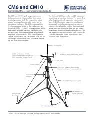
Appendix A. CM245 Adjustable AngleMounting StandA.1 InstallationThe CM245 includes slots that allow it to be adjusted to any angle fromhorizontal to vertical. If mounting the pyranometer at an angle, ensure that thecrossarm is leveled horizontally before placing the bracket at its proper angle.Angle positions are included on the bracket label (see FIGURE A-1 andFIGURE A-2).<strong>Pyranometer</strong>mounts hereFirst2.125 inU-boltSecond2.125 inU-boltFirst2.125 inU-bolt90Second2.125 inU-boltFIGURE A-1. CM245 bracket with 2.125 in. U-bolts positioned to mountthe pyranometer horizontally on a crossarmA-1
Appendix A. CM245 Adjustable Angle Mounting Standpn 17446pn 4365pn 4366pn 27291First1.5 inU-bolt40Second1.5 inU-boltpn 174461.50 inFIGURE A-2. CM245 bracket with 1.5 in. U-bolts positioned to mountpyranometer at a 40° angle on a vertical pipeDo the following to level the pyranometer horizontally:1. Attach the mounting stand to the crossarm.2. Loosely mount the pyranometer on the mounting stand. Do not fullytighten the two mounting screws.3. Turn the leveling screws as required to bring the bubble of the level withinthe ring.4. Tighten the mounting screws to secure the assembly in its final position.Check that the pyranometer is still correctly leveled and adjust as necessary.A-2
<strong>Campbell</strong> <strong>Scientific</strong> Companies<strong>Campbell</strong> <strong>Scientific</strong>, Inc. (CSI)815 West 1800 NorthLogan, Utah 84321UNITED STATESwww.campbellsci.com • info@campbellsci.com<strong>Campbell</strong> <strong>Scientific</strong> Africa Pty. Ltd. (CSAf)PO Box 2450Somerset West 7129SOUTH AFRICAwww.csafrica.co.za • cleroux@csafrica.co.za<strong>Campbell</strong> <strong>Scientific</strong> Australia Pty. Ltd. (CSA)PO Box 8108Garbutt Post Shop QLD 4814AUSTRALIAwww.campbellsci.com.au • info@campbellsci.com.au<strong>Campbell</strong> <strong>Scientific</strong> do Brasil Ltda. (CSB)Rua Apinagés, nbr. 2018 ─ PerdizesCEP: 01258-00 ─ São Paulo ─ SPBRASILwww.campbellsci.com.br • vendas@campbellsci.com.br<strong>Campbell</strong> <strong>Scientific</strong> Canada Corp. (CSC)14532 – 131 Avenue NWEdmonton AB T5L 4X4CANADAwww.campbellsci.ca • dataloggers@campbellsci.ca<strong>Campbell</strong> <strong>Scientific</strong> Centro Caribe S.A. (CSCC)300 N Cementerio, Edificio BrellerSanto Domingo, Heredia 40305COSTA RICAwww.campbellsci.cc • info@campbellsci.cc<strong>Campbell</strong> <strong>Scientific</strong> Ltd. (CSL)<strong>Campbell</strong> Park80 Hathern RoadShepshed, Loughborough LE12 9GXUNITED KINGDOMwww.campbellsci.co.uk • sales@campbellsci.co.uk<strong>Campbell</strong> <strong>Scientific</strong> Ltd. (CSL France)3 Avenue de la Division Leclerc92160 ANTONYFRANCEwww.campbellsci.fr • info@campbellsci.fr<strong>Campbell</strong> <strong>Scientific</strong> Ltd. (CSL Germany)Fahrenheitstraße 1328359 BremenGERMANYwww.campbellsci.de • info@campbellsci.de<strong>Campbell</strong> <strong>Scientific</strong> Spain, S. L. (CSL Spain)Avda. Pompeu Fabra 7-9, local 108024 BarcelonaSPAINwww.campbellsci.es • info@campbellsci.esPlease visit www.campbellsci.com to obtain contact information for your local US or international representative.