MV public distribution networks throughout the world - Schneider ...
MV public distribution networks throughout the world - Schneider ...
MV public distribution networks throughout the world - Schneider ...

Create successful ePaper yourself
Turn your PDF publications into a flip-book with our unique Google optimized e-Paper software.
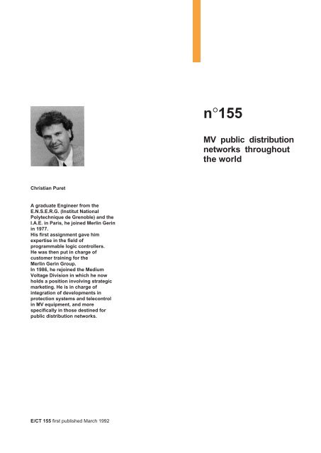
n°155<strong>MV</strong> <strong>public</strong> <strong>distribution</strong><strong>networks</strong> <strong>throughout</strong><strong>the</strong> <strong>world</strong>Christian PuretA graduate Engineer from <strong>the</strong>E.N.S.E.R.G. (Institut NationalPolytechnique de Grenoble) and <strong>the</strong>I.A.E. in Paris, he joined Merlin Gerinin 1977.His first assignment gave himexpertise in <strong>the</strong> field ofprogrammable logic controllers.He was <strong>the</strong>n put in charge ofcustomer training for <strong>the</strong>Merlin Gerin Group.In 1986, he rejoined <strong>the</strong> MediumVoltage Division in which he nowholds a position involving strategicmarketing. He is in charge ofintegration of developments inprotection systems and telecontrolin <strong>MV</strong> equipment, and morespecifically in those destined for<strong>public</strong> <strong>distribution</strong> <strong>networks</strong>.E/CT 155 first published March 1992
glossaryConfiguration : an operation, in bothdigital protection and telecontrolsystems, that involves assigning, viaei<strong>the</strong>r a built-in or a loaded softwarepackage, a standard piece ofequipment to a specific application.The latter operation, loading a softwarepackage, is carried out using a tool :<strong>the</strong> configurator, normally a personalcomputer PC. This allows for example:■ definition of functions that <strong>the</strong>equipment will perform,■ devising of connections with <strong>the</strong>environment,■ creation of mimic diagrams andlabelling of alarms for users.Draw-out (part of an assembly)(IEC 50 - chapter 441, NF C 01- 441) :withdrawable part of an assembly that,whilst remaining mechanically attachedto <strong>the</strong> assembly, can be moved to <strong>the</strong>position or one of <strong>the</strong> positions thatgives an insulating distance or a metalseparation between open contacts.This insulating distance or metalseparation always intervenes in <strong>the</strong>main circuit. It may or may not alsointervene in auxiliary circuits.Fixed (fixed device),(IEC dictionary of electricity) :a device that is designed to bemounted on a fixed support andintended to be connected to externalcircuits using fixed electricalconductors.Cut-out type fuse : <strong>MV</strong> striker-typefuse, that performs <strong>the</strong> two functions ofprotection and isolation. Isolationoccurs when <strong>the</strong> fuse melts by ejectionof <strong>the</strong> striker which in turn automaticallytriggers switch-over of <strong>the</strong> fusecartridge.Fault passage indicator : a devicefitted to <strong>MV</strong> <strong>networks</strong> that indicates,fault passage ei<strong>the</strong>r locally or at adistance. In order to improve quality ofservice, <strong>the</strong> operating company makesevery effort to reduce <strong>the</strong> interruption insupply to that part of <strong>the</strong> network inwhich <strong>the</strong> fault exists. To achieve this<strong>the</strong>y must know which portion of <strong>the</strong>network is affected by <strong>the</strong> fault. Withthis aim, <strong>the</strong> operating company installsfault passage indicators. Analysis of <strong>the</strong>information provided enables <strong>the</strong> faultyarea to be closed off, followed byreconfiguration of <strong>the</strong> network (typicalremote control application)Prediction : a new science with <strong>the</strong>objective of event prediction, it is basedon reasoning and scientific deduction.Recloser : <strong>MV</strong> circuit breakerincorporating a multishot autoclosingrelay, installed on an overhead <strong>MV</strong>feeder and coordinated with protectiondevices (fuses) placed on <strong>the</strong> feeder(upstream and downstream). It is usedin North-American type <strong>distribution</strong><strong>networks</strong>.Sectionaliser : <strong>MV</strong> switch equippedwith a fault passage counter, it isinstalled downstream of a <strong>MV</strong>overhead feeder protected by arecloser. Its automatic control counts<strong>the</strong> number of fault current passages(corresponding to <strong>the</strong> number of times<strong>the</strong> recloser is activated), and when apreset number has been reached itopens <strong>the</strong> circuit breaker. Selectivitycan thus be obtained by installingseveral sectionalisers in series on a<strong>MV</strong> feeder, <strong>the</strong> last sectionaliser(which is fur<strong>the</strong>st from <strong>the</strong> recloser)opening on <strong>the</strong> second instance ofcurrent fault, <strong>the</strong> precedingsectionaliser opening on <strong>the</strong> thirdoccasion and so on. This device isused in North-American type<strong>distribution</strong> <strong>networks</strong>.Cahier Technique Merlin Gerin n° 155 / p. 2
<strong>MV</strong> <strong>public</strong> <strong>distribution</strong> <strong>networks</strong><strong>throughout</strong> <strong>the</strong> <strong>world</strong>table of contents1. Different types of electrical The transmission and p. 4<strong>networks</strong>interconnection networkThe subtransmission network p. 5The <strong>MV</strong> network p. 5The LV network p. 6Type of electric current p. 6Network planning p. 62. The distributor Reason of existence p. 7His role p. 7His development p. 83. <strong>MV</strong> network topologies Criteria in choosing a topology p. 10Items that depend on p. 10<strong>the</strong> chosen topologyVarious <strong>MV</strong> network layouts p. 10Neutral earthing layouts p. 12Protection system p. 13Telecontrol system p. 144. <strong>MV</strong> Public <strong>distribution</strong> Substations on <strong>MV</strong> <strong>networks</strong> p. 15O<strong>the</strong>r <strong>MV</strong> installations p. 16<strong>MV</strong> switchgear p. 16French and p. 18North-American layouts5. Protection and control <strong>MV</strong> protection device technology p. 20of <strong>MV</strong> <strong>networks</strong> Electromagnetic compatibility p. 21<strong>MV</strong> control applications p. 21<strong>MV</strong> telecontrol architectures p. 23Communications <strong>networks</strong> p. 246. Conclusion p. 25Appendix 1: some <strong>MV</strong> product standards p. 26Appendix 2: various selectivity techniques p. 26Appendix 3: EDF architecture and Merlin Gerin equipment p. 27Appendix 4: references p. 28In a country, <strong>the</strong> Transmission andPublic Distribution <strong>networks</strong> ensure <strong>the</strong>transfer of electrical energy from pointsof production to consumer units.The points of production are powerstations that generate electrical energyfrom various primary energy sources(nuclear, hydro-electric, coal....)The points of consumption in<strong>MV</strong> - Medium Voltage -, aresubstations, from which <strong>the</strong> energy isdelivered to customers (subscribers).This takes place via <strong>the</strong> “<strong>MV</strong><strong>distribution</strong> system “wich is <strong>the</strong> object ofthis “Cahier Technique“ report.In this “Cahier Technique“ report, afterhaving described <strong>the</strong> various types of<strong>distribution</strong> <strong>networks</strong> and <strong>the</strong>distributor’s role, <strong>the</strong> reader who is notfamiliar with <strong>MV</strong> will find details on:■ topologies of <strong>MV</strong> <strong>networks</strong>,■ substations,■ protection and telecontrol devices.Comment: In this “Cahier Technique“report, <strong>the</strong> term <strong>MV</strong> applies to anyvoltage from a few kV to 40 kV.Cahier Technique Merlin Gerin n° 155 / p. 3
1. different types of electrical <strong>networks</strong>Producing electrical current in powerstations is not enough in itself, it mustalso be brought to <strong>the</strong> end-user.In order to link production andconsumption, which in turn can betranslated into financial benefit, acountry’s electrical structure isgenerally broken down into severallevels that correspond to different typesof electrical <strong>networks</strong>. (see fig. 1).It should be noted that <strong>the</strong>re is nostandard structure that exists<strong>world</strong>wide, and that <strong>the</strong> split intoseveral <strong>networks</strong> with <strong>the</strong>ircorresponding voltage levels can bedifferent from country to country.However, in general <strong>the</strong> number ofvoltage levels is limited to three; indeedin 1983 <strong>the</strong> IEC <strong>public</strong>ation 38formulated recommendations forvoltage levels for 50 and 60 Hz<strong>networks</strong>.However, in order to gain betterunderstanding of this split, <strong>the</strong> followingparagraphs present each grid with:■ its object,■ its voltage level,■ its structure.<strong>the</strong> transmission andinterconnection networkThe geographical distance betweenproduction sites and consumer centres,<strong>the</strong> irregularity of consumption and <strong>the</strong>impossibility of storing electrical energycreate <strong>the</strong> need for an electricalnetwork that is capable of directing andtransmitting it across large distances.These lines can stretch acrossthousands of kilometers , forexample in <strong>the</strong> French network <strong>the</strong>reexists 20 000 km.fig. 1: illustrated layout of an electrical network showing that electricity is produced, carried and distributed at various voltage levels.Cahier Technique Merlin Gerin n° 155 / p. 4
The object of this network is threefold:■ a "transmission" function with <strong>the</strong> aimof carrying electricity from producingpower stations to <strong>the</strong> main consumerzones;■ a "national interconnection" functionthat manages <strong>the</strong> product <strong>distribution</strong>by relating <strong>the</strong> production to <strong>the</strong>geographical and time-dependantnature of demand;■ an "international interconnection"function - that manages energy fluxbetween countries dependant onprogrammed exchanges or as back-up.In general only very few customers witha high consumption are connected to<strong>the</strong>se <strong>networks</strong>.These <strong>networks</strong> are essentially ofoverhead type structure.The voltages are normally between 225and 400 kV, and sometimes 800 kV(e.g.: 765 kV in South Africa). Use ofsuch high voltages is tied in with costsaving objectives. Indeed for a givenpower, <strong>the</strong> line losses by Joule effectare inversely proportional to <strong>the</strong> squareof <strong>the</strong> voltage:p = k/U 2 , withU= network voltage,k = constant - dependant on <strong>the</strong> line.In addition <strong>the</strong> transmitted powervalues are such that using low voltageswould require totally unrealistic cablecross-sections. Use of high voltages isthus imposed in spite of <strong>the</strong> drawbacksinvolved in higher equipment insulationcosts, <strong>the</strong> easiest solution being <strong>the</strong>use of overhead lines.In any case, <strong>the</strong> choice of transmissionvoltage is above all a technico-economicone, dependant on <strong>the</strong> power to betransmitted and <strong>the</strong> distances to becovered.The safety aspect is fundamental for<strong>the</strong>se <strong>networks</strong>. Indeed any fault at thislevel leads to important supply failuresfor all consumer units. In 1965 in <strong>the</strong>United States, 30 million people werewithout electricity for 12 hours due tosuch a fault.These <strong>networks</strong>’ protection systemsmust be very high-performance. As for<strong>the</strong>ir operation on a national level, thisis <strong>the</strong> task of a control centre fromwhich <strong>the</strong> electrical energy ispermanently monitored and managed.<strong>the</strong> subtransmissionnetworkThe object of this network is essentiallyto carry electricity from <strong>the</strong> transmissionnetwork to <strong>the</strong> main consumer centres.These consumer centres are:■ ei<strong>the</strong>r from <strong>the</strong> <strong>public</strong> sector withaccess to <strong>the</strong> <strong>MV</strong> network,■ or from <strong>the</strong> private sector with accessto high-consumption customer (greaterthan = 10 <strong>MV</strong>A) supplied directlywith HV. In any country <strong>the</strong> number ofsuch consumers is very small (e.g. 600in France). They are essentiallyindustries such as iron and steel,cement, chemicals, rail transport,....The structure of <strong>the</strong>se <strong>networks</strong> isgenerally of overhead type (sometimesunderground near urban areas). In thisrespect environmental concerns (carefor <strong>the</strong> environment and protection ofcertain natural sites) are often raised inopposition to <strong>the</strong> construction of lines.As a result it is more and more difficultand expensive for subtransmission<strong>networks</strong> to reach high populationdensity areas.Voltage in <strong>the</strong>se <strong>networks</strong> is between25 kV and 275 kV.The protection systems are of <strong>the</strong> samekind as those for transmission<strong>networks</strong>, <strong>the</strong> control centres beingregional.% 100908070605040302010560270<strong>the</strong> <strong>MV</strong> networkThis level of a country’s electricalstructure will be covered in more detailin <strong>the</strong> chapters that follow. Thus, herewe only give a few distinguishingfeatures.The object of this network is to carryelectricity from <strong>the</strong> subtransmissionnetwork to points of mediumconsumption (greater than 250 KVAin France).These consumer points are:■ ei<strong>the</strong>r in <strong>the</strong> <strong>public</strong> sector, withaccess to <strong>MV</strong>/LV <strong>public</strong> <strong>distribution</strong>substations,■ or in <strong>the</strong> private sector, with access todelivery substations for mediumconsumption users. The number of<strong>the</strong>se customers (e.g. 160 000 inFrance) is only a small proportion of <strong>the</strong>total number of customers supplieddirectly with LV. They are essentiallyfrom <strong>the</strong> tertiary sector, such ashospitals, administrative buildings,small industries,...The structure is of overhead orunderground type.Voltage in <strong>the</strong>se <strong>networks</strong> ranges froma few to 40 kV (see fig. 2).Operation of <strong>the</strong>se <strong>networks</strong>, can becarried out manually or, morefrequently, by remote control from fixed/mobile control centres. However, inorder to account of specific needs for5 5< 12 kV 12 < U < 17 kV 17 < U < 24 kV > 24 kVfig. 2: proportion of various voltage levels within national <strong>MV</strong> <strong>networks</strong> as a function of <strong>the</strong>lengths of lines of each country.95352510310Belgium France Great Britain Italy Japan8095Cahier Technique Merlin Gerin n° 155 / p. 5
control of <strong>MV</strong> <strong>networks</strong>, <strong>the</strong>se controlcentres are different to those used ontransmission and subtransmission grid.The number and <strong>the</strong> geographicaldispersion of remote control units, <strong>the</strong>management of several simultaneouscontrol centres, <strong>the</strong> number and level ofqualifications of <strong>the</strong> operators allrequire appropriate solutions:ergonomics and user-friendly type workstations, control assistance tools,control centre configuration tools, andmanagement of <strong>the</strong> varioustransmission devices that are used.<strong>the</strong> LV networkThe object of this network is to carryelectricity from <strong>the</strong> <strong>MV</strong> network topoints of low consumption (less than250 KVA in France) in <strong>the</strong> <strong>public</strong> sectorwith access to LV customers.It represents <strong>the</strong> final level in anelectrical structure.This network enables supply to a verylarge number of consumers (26 millionin France) corresponding to <strong>the</strong>domestic sector.Its structure, whe<strong>the</strong>r overhead orunderground is often influenced by <strong>the</strong>environment.Voltages in <strong>the</strong>se <strong>networks</strong> arebetween 100 and 440 V.Such <strong>networks</strong> are often operatedmanually.type of electric currentEnergy transmission on <strong>the</strong>se various<strong>networks</strong> is accomplished using electriccurrent.Direct current or HVDC (high voltagedirect current) links are used forexchanges between countriesexclusively on a transmission networklevel. The choice of this techniqueenables optimization of <strong>the</strong> use oftransmission cables, particularly bycancelling <strong>the</strong> "skin" effect. Suchintercontinental and even continentallinks exist, for example a link betweenItaly and Sardinia via Corsica (300 MW/200 kV).In o<strong>the</strong>r cases, particularly <strong>public</strong> <strong>MV</strong><strong>networks</strong>, links are through alternatingcurrent. Indeed, in <strong>the</strong>se <strong>networks</strong>, <strong>the</strong>use of direct current would not beprofitable:■ losses reduced on short <strong>networks</strong>(less than 100 km),■ equipment made more expensive(requirement of numerous direct/alternating converters).In addition, alternating current is verywell adapted to voltage changes(transformers) in <strong>the</strong> course of itstransmission as electrical energy.With very few exceptions (SaudiArabia), and outside of <strong>the</strong> Americancontinent where 60 hertz is used<strong>throughout</strong>, <strong>the</strong> current frequencyis 50 hertz.Of particular note is <strong>the</strong> case of Japanwhere half of <strong>the</strong> country is on 60 hertz,and <strong>the</strong> o<strong>the</strong>r half on 50 hertz.network planningThe installation and evolution of <strong>the</strong>structure of an electrical supply networkfor a country corresponds to planningoperations.For transmission and subtransmission,<strong>the</strong>se operations are generallycentralised, since:■ <strong>the</strong> decisions leading to amodification in <strong>the</strong> structure of such<strong>networks</strong>, for example <strong>the</strong> introductionof a new <strong>MV</strong>/LV substation, requires totake into account numerous technicaland economical parameters;■ <strong>the</strong> number of <strong>the</strong>se parametersinvolved and <strong>the</strong>ir possible interactionsmeans that help from computerizedtools is required, such as use of a databaseand of expert systems.For <strong>MV</strong> and LV <strong>networks</strong>, <strong>the</strong> planningis, however, often decentralized.Cahier Technique Merlin Gerin n° 155 / p. 6
2. <strong>the</strong> distributorreason of existance:to supply electricityThe electrical energy distributors existto supply electrical energy toconsumers taking into account severalobjectives such as:■ continuity and quality of service,■ safety of people and goods,■ flexibility and ease of operation,■ commercial competitiveness.his roleIf electricity supply is satisfactory inindustrialized countries, <strong>the</strong> degree ofelectrification still remains variable incertain o<strong>the</strong>r countries.Varying objectives depending on <strong>the</strong>degree of electrification...For countries that are not 100%electrified, <strong>the</strong> priority objective remains<strong>the</strong> improvement of this degree ofelectrification. To this end, investmentis mostly in construction of <strong>networks</strong>and installations (see fig. 3).However, <strong>the</strong> investment capabilities,sometimes reduced, can lead tosolutions based on simplification of <strong>the</strong><strong>networks</strong>’ structure to <strong>the</strong> detriment of<strong>the</strong> system performance. In <strong>the</strong> sameway, sometimes a lack of availabilityand competence of <strong>the</strong> operators canlead to over-simplified operation.Varying situations in industrializedcountriesIn countries that are 100% electrified,<strong>the</strong>re are considerable differences inuses of electrical energy:■ national electrical energyconsumptions show great differences(see fig. 4). These differences are dueto <strong>the</strong> size of country, to its economicgrowth (GNP) and to <strong>the</strong> weight of <strong>the</strong>industrial sector (example 40% of <strong>the</strong>French consumption).■ per capita consumption can vary by afactor of 10 between certain countries(see fig. 4). These differences aremostly due to <strong>the</strong> pricing policy ofdistributors, but also to climaticconditions.The role of <strong>the</strong> <strong>MV</strong> distributor is notclear-cut: it often covers LV - LowVoltage - <strong>distribution</strong> and in somecases he is also in charge oftransmission, for example:■ in Japan, nine regional privatecompanies are each responsible for <strong>the</strong>production, transmission and<strong>distribution</strong> for <strong>the</strong>ir area,■ in Germany around a thousandcompanies are involved in <strong>the</strong><strong>distribution</strong> of electricity. Around 1/3have <strong>the</strong>ir own production facilities.■ in Great Britain production is <strong>the</strong>responsibility of two companies (NP -National Power - and PG - Power Gen).The NGC (National Grid Company) arein charge of transmission, and <strong>the</strong>regional <strong>distribution</strong> is looked after byaround twelve Regional ElectricityCompanies. This structure is a result ofa privatisation bill for British distributorsvoted in 1990.■ in Italy a law founded <strong>the</strong> E.N.E.L. in1962. This is a <strong>public</strong> serviceresponsible for <strong>the</strong> production,3000100030010030Net consumption / countryTWh19186027520010827901833190 2945320fig. 4: net consumption per country and per inhabitant.transmission and <strong>distribution</strong>; itmanages around 80% of <strong>the</strong> electricitydistributed in Italy.■ in France <strong>the</strong> situation is similar with<strong>the</strong> E.D.F.transformers= 5%lines+ poles+ total installation= 90%Net consumption / inhabitantKWh5954900<strong>MV</strong> switchgear= 5%fig. 3: break-down of costs of <strong>MV</strong> overheadlines.235511760Portugal Denmark Spain Italy France Japan United states300001000030001000300Cahier Technique Merlin Gerin n° 155 / p. 7
These examples would thus appear toshow that <strong>the</strong> number of partiesinvolved, particularly in <strong>MV</strong> <strong>distribution</strong>,can vary considerably from country tocountry (see fig. 5).In <strong>the</strong> case of <strong>MV</strong> <strong>distribution</strong> <strong>the</strong>distributor generally has completeresponsibility for <strong>the</strong> network, from <strong>the</strong>HV/<strong>MV</strong> substation to <strong>the</strong> <strong>MV</strong>/LVtransformer substation. In addition <strong>the</strong>distributor’s job now includes acommercial aspect with respect to <strong>the</strong>sale of "electricity" as a product in <strong>the</strong>form of a kWh. He must thuscontinually improve <strong>the</strong> quality of <strong>the</strong>product to satisfy <strong>the</strong> demands of hisvarious customers, and remaincompetitive in relation to o<strong>the</strong>r sourcesof energy. This objective leadsdistributors to consider several pricelevels dependant on <strong>the</strong> quality of kWhbeing sold.Equally, <strong>the</strong> electrical networkrepresents an important investment for<strong>the</strong> distributor. He has to make thisinvestment as profitable as possibleand it is for this reason that it isincreasingly frequent that distributors’requirements include <strong>the</strong> idea of energymanagement.Lastly, distributors play an importantsocial and political role, a role whichcan have a bearing on his choices, orat least on <strong>the</strong>ir priorities, as in <strong>the</strong>following two examples:■ supplying new customers mayrequire extension of <strong>the</strong> network,■ <strong>the</strong> price per kWh may be limited inline with government economic policy.his development: supply ofhigh quality energyIncreasingly, <strong>the</strong> energy distributor isrequired to supply a high qualityelectricity product. In order to do thishe must:■ reduce <strong>the</strong> number and <strong>the</strong> length ofinterruptions in supply to his customers,■ minimise <strong>the</strong> consequences of <strong>the</strong>m,■ avoid disruptions such as voltage andfrequency fluctations (see fig. 6).The type of faults depend on <strong>the</strong>type of networkFor customers, <strong>the</strong> consequences ofsuch phenomena depend above all on<strong>the</strong> type of fault.A fault can be:■ momentary or permanent in duration;■ one-phase or three-phase dependanton <strong>the</strong> type of its cause.A momentary fault often means a briefinterruption of <strong>the</strong> order of several100 ms, essentially related to <strong>the</strong>operating time of a recloser.country number of distributors <strong>the</strong> most importanttotal distributing 80%of nationalconsumptionGermany 600 20 R . W . E.Saudi arabia 5 5 S . C . E . C . O .Spain 200 6 Hydro ElectricaFrance 200 1 E . D . F .Great Britain 15 10 Regional Electricities C ieItaly 150 1 E . N . E . L .Japan 9 9 Tokyo Electric Power Cofig. 5: electrical energy distributors in several countries.parameters nominal tolerancesvaluesFrequency (50 Hz) ± 1Hz<strong>MV</strong> Voltage (12 to 24 kV) ± 7%LV Voltage (230 or 400V)overhead ± 10%underground ± 5%fig. 6: examples of a distributors "quality"constraints (EDF France).A permanent fault implies aninterruption lasting between severalminutes to several hours ; it requireshuman intervention.Overhead <strong>networks</strong>, that are naturallyconsiderably more exposed thanunderground grid, require specificsolutions to problems encounteredsuch as:■ tree branches falling on overheadlines;■ birds landing on <strong>the</strong> line or itssupports;■ faults due to lightning, wind, frost,snow;■ vandalism.As a consequence, <strong>the</strong> type of failuresencountered differ between overheadand underground <strong>networks</strong>:■ on overhead <strong>networks</strong>, <strong>the</strong> faults aremostly momentary (80 to 90%) andone-phased (75%) since <strong>the</strong>y are oftendue for example to storms, to a linefallen to <strong>the</strong> ground or to shortingacross an insulator.■ on underground <strong>networks</strong>, <strong>the</strong> faultsare mostly permanent (100%) andmulti-phased (90%) since <strong>the</strong>y are veryoften <strong>the</strong> result of severing a cable.A need for informationThe importance of understanding <strong>the</strong>incidents occuring on <strong>the</strong> networkincreasingly justifies a need forinformation that distributors satisfy byusing statistical studies.This analytical work aims to:■ classify and code <strong>the</strong> incidents,■ determine <strong>the</strong>ir origins and causes,■ statistically calculate <strong>the</strong>ir frequencies,■ search for correlations,■ study <strong>the</strong> comparative performancesof <strong>the</strong> various topologies,■ analyse <strong>the</strong> results according tooperating methods and installedequipment involved.These statistics provide a tool forhelping distributors in <strong>the</strong> design,operation and maintenance of <strong>public</strong><strong>networks</strong>.In addition, in order to be able to decideon <strong>the</strong> best solutions, <strong>the</strong> quality ofservice must be able to be quantifiedand measured, and no longer just beapproached in a subjective manner.In order to achieve this, new tools havebeen designed (based on ma<strong>the</strong>maticalmodels), particularly including <strong>the</strong> ideaof "undistributed energy". Notably, tomeasure <strong>the</strong> cost of low quality inCahier Technique Merlin Gerin n° 155 / p. 8
<strong>MV</strong> <strong>networks</strong>, <strong>the</strong> E.D.F. use <strong>the</strong>formula:A*N*N*P + B*N*P*T, withN = number of permanent breaks perfeeder,P = average power per feeder in kW,T = average length of interruption perfailure,A and B = economic value coefficients(in 1990, for <strong>the</strong> EDF in FranceA = 6 FF/ kW and B = 13.5 FF/ kWh).However, measurement of <strong>the</strong> qualityof service can require inclusion of evenmore parameters. The complexity of<strong>the</strong> calculations and simulations to becarried out, justifies <strong>the</strong> development ofsoftware tools that are increasinglypowerful to help with <strong>the</strong> decision.To measure <strong>the</strong> reliability of energysupply to a residential LV customer,distributors prefer to use <strong>the</strong> criteria of"degree of unavailability": this is <strong>the</strong>total annual time during which anaverage customer has his supplyinterrupted due to a fault on <strong>the</strong>electrical network (HV, <strong>MV</strong> or LV).Lastly, it is important to note that for aLV customer, numerous incidents aredue to <strong>the</strong> <strong>MV</strong> network (60% accordingto an EDF study) (see fig. 7).Networks, equipment and operators,are all evolvingIt should not be forgotten that anetwork’s performance depends aboveall on its topology. However, <strong>throughout</strong><strong>the</strong> <strong>world</strong>, present <strong>networks</strong> are simply<strong>the</strong> result of years of laying ofstructures one on top of <strong>the</strong> o<strong>the</strong>r asneeds have increased. In addition anetwork ages and is constantly in needof maintenance and renovation work toretain its performance level and toavoid incidents, <strong>the</strong> sources of"undistributed energy".To answer <strong>the</strong>se needs, <strong>the</strong>manufacturers thus propose"maintenance-free" or reducedmaintenance equipment; equipment forwhich maintenance, modification andaddition type operations do notadversely effect <strong>the</strong> continuity ofservice.In addition, energy distributors are notwilling to undertake preventivemaintenance, particularly devicemonitoring by recording and analysingincidents that occur on <strong>the</strong> network(use of "disturbance recorders" andtime-stampers).Advances in protection and telecontrolequipment with digital technology(microprocessor) and expansion ofcommunication <strong>networks</strong>, offer <strong>the</strong>perspective of innovative solutions interms of event prediction (seeglossary).Lastly, <strong>the</strong> practice of live-line repairwork and remote control of <strong>the</strong><strong>networks</strong> are also points that favourincreased quality of service, byreducing <strong>the</strong> number of interruptionsand <strong>the</strong>ir duration.Of course, all of <strong>the</strong>se developmentsrequire that <strong>the</strong> workforces shouldadapt quickly, following <strong>the</strong> example of<strong>the</strong> current changes in work practices in%number ofLV customers6050403020100control centres:■ <strong>the</strong>re still exists control centres inwhich:■ <strong>the</strong> status of various <strong>networks</strong> isindicated by manually displacedsymbols on large charts several meterssquare in area,■ and <strong>the</strong> instructions relating tooperations are hand written in logbooks;■ in new centres all <strong>the</strong>se operationsare performed on computer terminals,with:■ all information available on screens inreal time (network layouts,geographical description),■ events logged automatically (datalogging).1986 19950 1 2 3 4 5 >5 hoursduration of interruptionfig. 7: degree of unavailability of electrical energy on one LV network (EDF - France).Cahier Technique Merlin Gerin n° 155 / p. 9
3. <strong>MV</strong> network topologiesThe topology of an electrical network isdefined here as all of <strong>the</strong> principlesinvolved in carrying electrical energy in<strong>public</strong> <strong>distribution</strong> (layout, protection,operation).In practice for a distributor, defining atopology means fixing a certain numberof physical factors, whilst takingaccount of criteria dependant onobjectives aimed for and technicalconstraints. Since <strong>the</strong>se factors areclosely interrelated, choice of a certaintopology is always <strong>the</strong> result oftechnico-economic compromises.Here, <strong>the</strong> graphical representation of atopology will be by simplified single-linelayouts.criteria in choosing atopologyThe choice of a topology depends onmeeting objectives:■ to ensure <strong>the</strong> safety of people andgoods,■ to attain a pre-defined level of qualityof service,■ to produce <strong>the</strong> desired profitability.However, it must also meet certainrequirements:■ to correspond to <strong>the</strong> housing densityand/or to consumption, known as <strong>the</strong>load density, it plays an ever increasingrole. Calculated in units of <strong>MV</strong>A/km 2 ,this density enables <strong>the</strong> expression ofvarious geographical zones in terms ofload concentration. Certain distributorsdistinguish two types of consumptionzones by defining:■ low load density zone:< 1 <strong>MV</strong>A/km 2 ,■ high load density zone:> 5 <strong>MV</strong>A/km 2 .■ to account for <strong>the</strong> geographicalspread, terrain and constructionproblems,■ to satisfy environmental constraints,particularly climatic (maximum andminimum temperatures, frequency ofstorms, snow, wind, etc.) and respectfor surroundings.items that depend on <strong>the</strong>chosen topologyThe choice of a topology fixes <strong>the</strong> maindesign elements of a <strong>distribution</strong>system, such as:■ <strong>the</strong> rated power and <strong>the</strong> maximumvalue of earthing currents, e.g. for <strong>MV</strong>,<strong>the</strong> EDF limits <strong>the</strong> value of <strong>the</strong>securrents to 300 A at 20 kV overheadand to 1000 A underground;■ <strong>the</strong> rated voltages, e.g.:for <strong>MV</strong> Japansupplies at 6.6 kV, Great Britain at 11and 33 kV and France mostly at 20 kV;■ voltage surge ratings andcoordination of isolation as well asprotection systems against atmosphericvoltages surges;■ <strong>the</strong> earthing connection layouts, aswell as <strong>the</strong> number of distributed wires,■ <strong>the</strong> maximum feeder lengths (tens ofkilometers at <strong>MV</strong>);■ <strong>the</strong> type of <strong>distribution</strong>: overhead orunderground (see fig. 8);■ <strong>the</strong> type of operation: manual,automatic, remote controlled.It is important to note that:■ <strong>the</strong> choice of short circuit current hasrepercussions on <strong>the</strong> rating of <strong>the</strong>equipment used in <strong>the</strong> network;■ <strong>the</strong> choice of voltage rating(s) isalways a compromise between <strong>the</strong>installation and operating costs of <strong>the</strong>network;■ <strong>the</strong> choice of insulation rating ofequipment is generally in line withinternational and/ or national standards;GermanyCanadaUnited StatesDenmarkGreat BritainNe<strong>the</strong>rlands■ <strong>the</strong> choice of an overhead orunderground <strong>distribution</strong> system has abig influence on <strong>the</strong> installation costsand <strong>the</strong> quality of service (e.g.: costs ofa trench / vulnerability to momentaryfaults...). For <strong>MV</strong>, in industrializedcountries, this choice can be brokendown into three cases:■ highly populated urban area with anunderground <strong>distribution</strong> system,■ highly populated suburban area withunderground or part-underground partoverhead<strong>distribution</strong> system;■ scarcely populated rural area withoverhead <strong>distribution</strong>.However it should be noted thathistorically, due to high initial costs,numerous urban areas have overhead<strong>distribution</strong> systems, as in Japan and<strong>the</strong> United States.various <strong>MV</strong> network layoutsThe choice of layout is important to acountry: particularly for <strong>MV</strong> <strong>networks</strong>since <strong>the</strong>y are of great length. Thus, forexample, <strong>the</strong> total <strong>MV</strong> structure inFrance is around 570 000 km long, thatof Italy being 300 000 km long and thatof Belgium being 55 000 km long.Several topologies exist:■ lattice type, closed loop topology,■ simplified lattice type, open looptopology,■ open loop topology,■ radial topology.0 25 50 75 100%undergroundoverheadfig. 8: proportion of lengths of overhead (lines) and underground (cables) on <strong>MV</strong> <strong>networks</strong>, forseveral countries.Cahier Technique Merlin Gerin n° 155 / p. 10
O<strong>the</strong>r topologies are also used, forexample <strong>the</strong> double shunt found onFrench <strong>MV</strong> <strong>networks</strong>.Although none of <strong>the</strong>m are "standard"in <strong>MV</strong>, distributors lean towards twobase topologies: radial and open loop.Each of <strong>the</strong>se two topologies will thusbe covered in more detail and definedin terms of:■ its operating principle,■ its typical line layout,■ its typical application,■ its strengths and weaknesses.Radial layoutThis layout can also be calledantenna-type.Its operating principle is based on usinga single supply line. This means that allconsumer units in such a structure onlyhave one possible electrical feed path.It is of arborescent type (cf. fig. 9).This arborescence originates fromsupply points, that are <strong>MV</strong>/<strong>MV</strong> orHV/<strong>MV</strong> <strong>distribution</strong> substations.This layout is particularly used for <strong>MV</strong><strong>distribution</strong> in rural areas. Indeed, itenables easy and low-cost supply tolow load density (≈ 10 kVA) consumerunits with a wide geographicaldispersion (≈ 100 km 2 ).Very often a radial layout is used withan overhead type <strong>distribution</strong> system.Its strengths and weaknesses aresummarized in <strong>the</strong> table in figure 10.Open loop layoutIts operating principle uses two lines ofsupply. This means that any consumerfig. 10: comparative table of <strong>the</strong> two base <strong>MV</strong> network layouts.unit on this structure can be suppliedvia two possible electrical paths, whilstonly one of those paths is activated atany one time, back-up is provided by<strong>the</strong> possibility of using <strong>the</strong> o<strong>the</strong>r loop. Insuch a layout, <strong>the</strong>re is always an openpoint in <strong>the</strong> loop, which leads to asimilar operation to two antennalayouts.The typical line layout is, of course, aloop on which are connected consumerunits (see fig. 9) which can be <strong>public</strong><strong>distribution</strong> substations <strong>MV</strong>/LV, and/ ordelivery substations for a <strong>MV</strong> customer.technology strengths weaknessesradial ■ simplicity ■ quality of service■ operation■ installation costs.open loop ■ simplicity ■ operation with more■ quality of servicefrequent switching■ installation costsHV/ <strong>MV</strong>substationsHV/ <strong>MV</strong> transformersradial layoutopen loop layoutsupply path for all substations except n°1<strong>MV</strong>/ LVtransformersupply path forsubstation n°1<strong>MV</strong>/ LVtransformersubstation n°1<strong>MV</strong>/ LVtransformeropen point<strong>MV</strong>/ LVtransformerfig. 9: <strong>the</strong> two basic layouts of a <strong>MV</strong> <strong>distribution</strong> network, radial (or antenna) and open loop (or artery break).Cahier Technique Merlin Gerin n° 155 / p. 11
Each point (between 15 and 25 pointsper loop) is connected to <strong>the</strong> loop bytwo <strong>MV</strong> switches. All <strong>the</strong>se switchesare closed , except for one of <strong>the</strong>m thatforms <strong>the</strong> opening in <strong>the</strong> loop anddefines <strong>the</strong> feed path for eachconsumer unit. This opening can bedisplaced within <strong>the</strong> loop, particularlyduring reconfiguration operationsfollowing a fault.Very often this layout is used inassociation with an underground type<strong>distribution</strong> system.It is typically used in highly populatedurban areas, and its strengths andweaknesses are detailled in <strong>the</strong> table,figure 10.Double shunt layoutThis ra<strong>the</strong>r uncommon layout is mostlyused by <strong>the</strong> EDF in <strong>the</strong> Paris region, itis shown in figure 11.The operating principle is <strong>the</strong> following:■ <strong>the</strong> <strong>MV</strong> network is doubled up,containing two circuits A and B, bothnormally live,■ every <strong>MV</strong>/LV substation■ is connected to both <strong>MV</strong> cables ("A"and "B"), but it is only actually live toone of <strong>the</strong> cables (<strong>MV</strong> switch closed oncable "A"),■ is equipped with a simple localautomatic control device,■ on failure of cable "A", <strong>the</strong> automaticcontrol detects <strong>the</strong> lack of voltage in <strong>the</strong>cable, checks <strong>the</strong> presence of voltagein cable "B" and commands <strong>the</strong> closingof one <strong>MV</strong> switch and <strong>the</strong> opening of<strong>the</strong> o<strong>the</strong>r <strong>MV</strong> switch.The five neutral earthing layoutsused in <strong>MV</strong> <strong>throughout</strong> <strong>the</strong> <strong>world</strong>Here again, no one standard neutralearthing layout exists. However, it ispossible to bring toge<strong>the</strong>r all <strong>the</strong>various cases met around <strong>the</strong> <strong>world</strong>into five categories (see fig. 12):■ direct distributed neutral earthing,■ direct non-distributed neutral earthing,■ neutral earthing via an impedance,■ neutral earthing via a designatedcircuit,■ neutral insulated from earth.As has already been said, none of <strong>the</strong>categories is dominant <strong>throughout</strong> <strong>the</strong><strong>world</strong>: some solutions are specific tosome countries, and several categoriescan be found within one single country,or even within <strong>the</strong> network of one singleelectricity distributor.But in <strong>the</strong> end, <strong>the</strong> choice of a <strong>MV</strong>neutral earthing layout is always <strong>the</strong>result of a compromise betweeninstallation and operating costs.HV/ <strong>MV</strong>substationThe differences between <strong>the</strong> fivecategoriesIt has been previously stated that <strong>the</strong>choice of neutral earthing layoutinfluences <strong>the</strong> performance of <strong>the</strong>network and <strong>the</strong> design of its protectionsystem. Indeed, <strong>the</strong> main differencesbetween <strong>the</strong> five categories lie in <strong>the</strong>behaviour of <strong>the</strong> network in an earthfault situation.These differences translate in realterms to <strong>the</strong> degree:■ of ease of detection of <strong>the</strong>se faults,■ of security achieved for people,■ of impact on <strong>the</strong> requirements ofelectrotechnical equipment.The distributed neutral earthing layoutthat allows single phase <strong>distribution</strong>should, however, be consideredseperately. This possibility can beconsidered in certain countries on <strong>the</strong>basis of its reduced installation costs.However, <strong>the</strong> more complex protectiondevices require stricter maintenance.HV/ <strong>MV</strong>substationneutral earthing layoutsThe choice of neutral earthing layouts(or neutral <strong>MV</strong> systems) definesamongst o<strong>the</strong>r things <strong>the</strong> voltage surgeratings and earth fault currents thatcould be found on a network. It must benoted that <strong>the</strong>se two parameters arecontradictory, in view of <strong>the</strong> fact thatobtaining a low fault current level leadsto a high voltage surge and vice versa.These values thus pose electricalconstraints that <strong>the</strong> electrotechnicalequipment must be capable ofwithstanding. However, in choosing <strong>the</strong>connecting layout, we simultaneouslyselect <strong>the</strong> possible solutions forprotection of <strong>the</strong> electrical network andinfluence <strong>the</strong> operating methods.inlet Ainlet B<strong>networks</strong>uppliedby...tf = 5 or 25 stfig. 11: double shunt <strong>distribution</strong> layout, used by EDF - France. In <strong>the</strong> inset, automatic controlsequence of Merlin Gerin permutator, conforming to EDF - France specifications.Ucircuit "A"101010At fBcircuit "B"t fACahier Technique Merlin Gerin n° 155 / p. 12
Independantly of this particular case,<strong>the</strong> table in figure 13, a summary of <strong>the</strong>strengths and weaknesses of <strong>the</strong>secategories, shows why no one of <strong>the</strong>secategories is predominantly used<strong>throughout</strong> <strong>the</strong> <strong>world</strong>.protection systemThe electrical structure of a countrycorresponds to a group of electrical<strong>networks</strong>.An electrical network can itself bebroken down into areas.Each of <strong>the</strong>se areas is generallyprotected by a circuit breaker inconjunction with detector devices(measurement sensor: current orvoltage transformer...), protection andcontrol devices (protection relays), andtrip devices (actuators).All <strong>the</strong>se elements toge<strong>the</strong>r make up achain of protection (see fig. 14) thatensures isolation of <strong>the</strong> faulty part of<strong>the</strong> network in <strong>the</strong> event of a fault.Its role is to ensure safety by protectingagainst insulation faults betweenphases or between phase and earth,and against prolonged overloading. Thechain of protection must especiallyreduce <strong>the</strong> consequences of a shortcircuit, such as <strong>the</strong> risks of fire,explosion of mechanical damage,...The network’s protection system ismade up of all of <strong>the</strong>se chains ofprotection, integrating <strong>the</strong>ir installationwith <strong>the</strong> organization of <strong>the</strong> operationbetween <strong>the</strong>m. This protection systemorganization, including <strong>the</strong> trip times of<strong>the</strong> associated circuit breakers, defines<strong>the</strong> maximum duration of a current faultin <strong>the</strong> different parts of <strong>the</strong> electricalnetwork.The effectiveness of a protectionsystem depends on several criteria:reliability, selectivity, rapidity,sensitivity, adaptability.ReliabilityThis criterion describes <strong>the</strong> level ofquality concerning safety of people andproperty, particularly in terms ofdangers of electrocution by increasedearth potential. Although a protectiondevice is rarely activated, when <strong>the</strong>re isa fault it must act effectively, <strong>throughout</strong>its many years of service. This criteriondirectly influences <strong>the</strong> networkperformance, thus, for example, anymethodcountryAustraliaCanadaSpainFranceJapanGermanyneutraldistributedwith numerousearthing points■■neutralear<strong>the</strong>ddirectly andundistributed■neutralear<strong>the</strong>d viaan impedance■■neutralear<strong>the</strong>d viaa designatedcircuitfig. 12: various <strong>MV</strong> neutral earthing layouts, and <strong>the</strong>ir applications <strong>throughout</strong><strong>the</strong> <strong>world</strong>.■■neutralinsulatedfrom earthneutral earthing method strengths weaknessesdirect earthing authorises one-phase ■ requires numerous high qualityand distributed and three-phase earthing points (safety)<strong>distribution</strong>■ requires a complex protectionsystem■ leads to high values of earthfault currentsdirect to earth eases detection of leads to high values of earthand undistributed earthing faults fault currentsinsulated limits earth fault leads to surge overvoltagecurrentsdesignated favours auto-extinction requires complexof earthprotection systemsfault currentsimpedant(compared with neutral limits earth fault requires more complexdirect to earth) currents protection systems(compared with neutral reduces surge leads to higher earth faultinsulated from earth) overvoltage currentsfig. 13: a summary of strengths and weaknesses of <strong>the</strong> five <strong>MV</strong> neutral earthing methods.measurementsensorprotectionunitelectrical networkactuatorbreakerdevicefig. 14: <strong>MV</strong> chain of protection, and photograph of a SF set (Merlin Gerin), an example ofcomplete integration.■■Cahier Technique Merlin Gerin n° 155 / p. 13
interruption in supply must be "justified"since it entrains a loss of operation for<strong>the</strong> customer ... and <strong>the</strong> distributor.SensitivityThis criterion also has a bearing interms of security and costs: it describes<strong>the</strong> ability to detect weak fault currentswithout being sensitive to transitoryphenomena due to <strong>the</strong> network(operations) or to surroundingelectromagnetic effects, thus before<strong>the</strong>re is any risk to people or property,and that without tripping prematurely.SelectivityThis criterion has a particular bearingon costs of operation, since it indicatesto what degree it is possible to maintain<strong>the</strong> network operation whilst one part ofit is not working as it should do. Inpractice, this leads to shutting off <strong>the</strong>faulty element, and only <strong>the</strong> faultyelement (see appendix 2: differentselectivity techniques).RapidityThis criterion, as in <strong>the</strong> preceding case,has an effect on costs: it enablesreduction of <strong>the</strong> damage due toelectrical arcs and short circuit currents,it particularly reduces <strong>the</strong> risk of fireand <strong>the</strong> costs of repair work.AdaptabilityThis criterion particularly interests <strong>the</strong>distributor and indicates <strong>the</strong> degree ofevolution that is possible (possibilitiesand ease) for <strong>the</strong> protection systemwith regards to modifications to <strong>the</strong>network topology.Of all <strong>the</strong>se criteria, selectivity is <strong>the</strong>one that leads to <strong>the</strong> most variedsolutions from country to country. Theydepend on two initial choices made by<strong>the</strong> energy distributors:■ of which neutral earthing layout isused, from which we define notably <strong>the</strong>protection systems against earthingfaults (see previous section).■ and that of which selectivity principlewill be used, of which <strong>the</strong> mostcommonly used, called amperechronometricselectivity, is based on<strong>the</strong> association of <strong>the</strong> fault currentrating (amperemetric selectivity) and avalue of <strong>the</strong> tripping delay time(chronometric selectivity). However,several different techniques can existwithin <strong>the</strong> same network, in SouthAfrica for example E.S.C.O.M. useswithin one network, amperechronometricselectivity, pilot wirebetween HV/<strong>MV</strong> and <strong>MV</strong>/<strong>MV</strong>substations and biased differential forHV/<strong>MV</strong> transformers. Lastly, distanceselectivity technique is mostly used byGerman distributors.telecontrol systemUnder <strong>the</strong> one term of telecontrol aregrouped all of <strong>the</strong> elements tied in withoperation of <strong>the</strong> network.A telecontrol system defines all of <strong>the</strong>seelements and <strong>the</strong>ir relative operationalorganization. In this way <strong>the</strong> telecontrolsystem must enable <strong>the</strong> operator (<strong>the</strong>distributor) to account for 3 situations■ normal operation,■ <strong>the</strong> instance of a fault,■ maintenance operations (live anddead).Lastly, <strong>the</strong> operating tools installed inthis system are going to make aconsiderable contribution to <strong>the</strong> qualityof service that is obtained.These tools range from <strong>the</strong> push-buttoncontrol of a <strong>MV</strong> device up to <strong>the</strong> <strong>MV</strong>network control centre, from <strong>the</strong>ammeter on a <strong>MV</strong> cubicle up to aautomatic remote reading of <strong>the</strong> loadcurve for a <strong>MV</strong> feeder, etc...Cahier Technique Merlin Gerin n° 155 / p. 14
4. <strong>MV</strong> <strong>public</strong> <strong>distribution</strong>This chapter is a reminder of <strong>the</strong> mainsubstations installed on <strong>MV</strong> <strong>networks</strong>,and <strong>the</strong> main technologies used in <strong>MV</strong>equipment. It is concluded by twolayouts showing <strong>the</strong>ir applications inreal terms.substations on <strong>MV</strong><strong>networks</strong>A substation or installation is a physicalentity defined by its position and itsfunction within electrical <strong>networks</strong>.The role of a substation is essentially toperform <strong>the</strong> transition between twovoltage levels and/ or to supply <strong>the</strong> enduser.The HV/<strong>MV</strong> substation in a <strong>public</strong><strong>distribution</strong> systemThis installation is present in any of acountry’s electrical structures; it ispositioned between <strong>the</strong>subtransmission network and <strong>the</strong> <strong>MV</strong>network.Its function is to ensure transition fromHV (≈ 100 kV) to <strong>MV</strong> (≈ 10 kV).Its typical layout (see fig. 15) involvestwo HV inputs, two transformers HV/<strong>MV</strong>, and 10 to 20 <strong>MV</strong> feeders. Thesefeeders supply overhead lines and/ orunderground cables.The <strong>MV</strong>/<strong>MV</strong> substation in a <strong>public</strong><strong>distribution</strong> systemThis installation performs two functions:■ to ensure <strong>the</strong> demultiplication of <strong>MV</strong>feeders downstream of HV/<strong>MV</strong>substations (see fig. 15). In this case,<strong>the</strong> substation does not include atransformer. It is made up of 2 <strong>MV</strong>inputs and 8 to 12 <strong>MV</strong> feeders. Thistype of substation is used in severalcountries like Spain, Belgium, SouthAfrica.■ to transfer between two <strong>MV</strong> voltagelevels. Such <strong>MV</strong>/<strong>MV</strong> substations docontain transformers. They arenecessary in countries that use twosuccessive voltage levels in <strong>the</strong>ir <strong>MV</strong><strong>networks</strong>, for instance in Great Britainwhere <strong>the</strong> <strong>MV</strong> network is broken downinto two levels 11 kV and 33 kV. Theirtypical layout ressembles that of <strong>the</strong>HV/<strong>MV</strong> substation.The <strong>MV</strong>/LV substation in a <strong>public</strong><strong>distribution</strong> systemPositioned between <strong>the</strong> <strong>MV</strong> networkand <strong>the</strong> LV network, this installationHV/<strong>MV</strong>substation<strong>MV</strong>/<strong>MV</strong>substation<strong>MV</strong>/LVsubstationdeliverysubstation fora <strong>MV</strong> customer<strong>MV</strong> incomers<strong>MV</strong>incomersperforms <strong>the</strong> transfer from <strong>MV</strong>(≈ 10 kV) to LV (≈ 100 V).The typical layout of this substation isof course a lot more simple than <strong>the</strong>HV incomersHV/<strong>MV</strong> transformers<strong>MV</strong> bus sectioncircuit breakeroverhead and/or underground <strong>MV</strong> feeders<strong>MV</strong> incomersoverhead and/or underground <strong>MV</strong> feeders<strong>MV</strong>/LV transformerprotectiongeneral <strong>MV</strong> protectionand metering systemprivate <strong>MV</strong>feedersfig. 15: various layout types for substations used on <strong>public</strong> <strong>distribution</strong> <strong>networks</strong>LV feedersprivate LVfeedersCahier Technique Merlin Gerin n° 155 / p. 15
previous installations. In particular, <strong>the</strong>most common <strong>MV</strong> device used is <strong>the</strong>switch and no longer <strong>the</strong> circuitbreaker.These substations are made up of fourparts:■ <strong>MV</strong> equipment for connection to <strong>the</strong>upstream network,■ <strong>the</strong> <strong>MV</strong>/LV <strong>distribution</strong> transformer,■ <strong>the</strong> LV feeder board as connection to<strong>the</strong> downstream network (in LV),■ and inceasingly frequently a prefabricatedouter enclosure (in metal orincreasingly frequently in concrete) toenclose <strong>the</strong> previous elements.The delivery substation for a HV or<strong>MV</strong> customerThese installations perform <strong>the</strong> transferfrom <strong>public</strong> <strong>distribution</strong> to private<strong>distribution</strong>. They enable connection:■ to <strong>the</strong> HV subtransmission networkfor a high-consumption customer(≈ <strong>MV</strong>A) via a HV/<strong>MV</strong> substation,■ to <strong>the</strong> <strong>MV</strong> network of a mediumconsumptioncustomer (≈ 100 kVA) viaa <strong>MV</strong>/LV substation.The choice of <strong>the</strong> connecting voltage to<strong>the</strong> <strong>public</strong> <strong>distribution</strong> network for acustomer depends essentially on:■ <strong>the</strong> quality of <strong>the</strong> LV network,particularly its power capacity (electricalcapacity);■ <strong>the</strong> distributors policy, particularly on<strong>the</strong> rates offered, since for <strong>the</strong>customer this defines <strong>the</strong> cost savingadvantages of electrical energy,compared with o<strong>the</strong>r sources ofenergy: oil, gas,...In practice, it is <strong>the</strong> power subscribed toby <strong>the</strong> customer that determineswhe<strong>the</strong>r he is connected to LV or <strong>MV</strong>,with very different values from countryto country. Thus, in France a customeris supplied <strong>MV</strong> from 250 kVA whereasin Italy this threshold is nearer severaltens of kVA. On <strong>the</strong> o<strong>the</strong>r hand in <strong>the</strong>United States where a customer can besupplied LV up to 2500 kVA. For userssupplied with HV, <strong>the</strong> layout of <strong>the</strong>substation is specifically designed.However, if <strong>the</strong> user is supplied with<strong>MV</strong>, a standard layout may beproposed (see fig. 15). Installation ofsuch a substation is, however, evidentlydependant on <strong>the</strong> distributor’sagreement since <strong>the</strong>y may have <strong>the</strong>irown specific requirements (metering,operating conditions,...)o<strong>the</strong>r <strong>MV</strong> installationsOutside of <strong>the</strong> substations alreadydescribed, o<strong>the</strong>r <strong>MV</strong> installations existthat are mainly positioned on overhead<strong>networks</strong>. Often single function, <strong>the</strong>yare used■ ei<strong>the</strong>r as protection, as in <strong>the</strong> case offuses and reclosers (glossary).■ or for operation, as in <strong>the</strong> case ofremote control switches.The <strong>MV</strong> remote control switch is part ofnetwork remote control systems. Itallows rapid reconfiguration operationswithout <strong>the</strong> operator having to travel.<strong>MV</strong> switchgear (see appendix 1)<strong>MV</strong> switchgear enables <strong>the</strong> threefollowing basic functions to beperformed:■ isolation, which consists of isolating apart of <strong>the</strong> network in order to work on itin complete safety,■ control, that consists of opening orclosing a circuit under its normaloperating conditions,■ protection, that consists of isolatingpart of a network with a fault in it.It essentially takes three forms:■ separate devices (see fig. 16)(directly fixed on a wall and protectedfrom access by a door),■ metal enclosures (or <strong>MV</strong> cubicles)containing <strong>the</strong>se devices,■ <strong>MV</strong> boards that are made up ofseveral cubicles.The use of separate devices isincreasingly rare; only several countriessuch as Turkey or Belgium, still use thistechnology.Amongst all <strong>the</strong> various types ofdevices, two are particularly used in <strong>MV</strong>switchgear, <strong>the</strong> circuit breaker and <strong>the</strong>switch. They are virtually alwayscombined with o<strong>the</strong>r devices (protectionand telecontrol units, sensormeasurement units,...) that make up<strong>the</strong>ir associated equipment.■ <strong>MV</strong> circuit breakerIts main function is protection, but alsoperforms a control function and,depending on its type of installation, aswitching function (draw-out, glossary).<strong>MV</strong> circuit breakers are nearly alwaysmounted in a <strong>MV</strong> cubicle.■ <strong>MV</strong> switchIts main function is command, but alsooften performs a role of switching. Inaddition, it is combined with <strong>MV</strong> fusesto ensure protection of <strong>MV</strong>/LVtransformers (30% of all <strong>MV</strong> switchesused).<strong>MV</strong> cubicles have metal enclosures thatmeet specifications laid down in <strong>the</strong><strong>public</strong>ation IEC 298 that differentiatesfour types of switchgear, each typecorresponding to a level of protectionagainst fault propagation within acubicle.This protection system involvespartitioning of <strong>the</strong> cubicle into threebasic compartments (see fig. 17):■ <strong>the</strong> switchgear compartmentcontaining <strong>the</strong> device (<strong>MV</strong> circuitbreaker, <strong>MV</strong> switch,...),■ <strong>the</strong> <strong>MV</strong> busbars for electricalconnections between several <strong>MV</strong>cubicles grouped toge<strong>the</strong>r on a board,■ <strong>MV</strong> cable connections compartment,often with space for measurementsensors.Often a fourth compartment completesthis assembly, it being <strong>the</strong> controlcompartment (or LV box) containingprotection and control units.In addition to this classification <strong>the</strong>distinction should be noted betweenFixed and Draw-out (see glossary) thatapply to <strong>the</strong> <strong>MV</strong> device and cubicle.This distinction, that depends on <strong>the</strong><strong>MV</strong> devicesfunctionisolatingcommandprotectionisolator switch circuit breaker switch isolator draw-outcircuit breaker■■■■ ■ ■ ■■■fuse■fig. 16: various functions of <strong>MV</strong> devices that are used in <strong>public</strong> <strong>distribution</strong>(contactors are essentially used in industry).Cahier Technique Merlin Gerin n° 155 / p. 16
connection and measurementmeasurement transformercontrolsubstationswitchgearseparate device<strong>public</strong>HV/<strong>MV</strong><strong>public</strong><strong>MV</strong>/<strong>MV</strong><strong>public</strong><strong>MV</strong>/LVSHV/<strong>MV</strong>customer<strong>MV</strong>/LVcustomerSswitchgearcircuitbreakerbloccompartmentedCB or SCB or SSSCBCBCB or SCB or Sincomerfeedermetal cladCBCBCBbusbarsGISCBCBfig. 17: various compartments of a <strong>MV</strong>cubicle, surrounded with a metal enclosure,and <strong>the</strong>ir main elements.RMUSS = with switch CB = with circuit breakerfig. 18: main <strong>MV</strong> switchgear applications.Sease of operation (as a function of timetaken to change a device), is onlyindirectly involved in <strong>the</strong> idea of <strong>MV</strong>network safety.IEC 298 defines <strong>the</strong> following four typesof switchgear for <strong>MV</strong> cubicles:■ "BLOC" switchgear divided to agreater or lesser extent intocompartments;■ "COMPARTIMENTED" switchgear, ofwhich only <strong>the</strong> outer enclosure isobliged to be metal, has <strong>the</strong> threecompartments separated with metal orinsulated partitions;■ "METAL CLAD" switchgear also hasdistinct compartments, but of which <strong>the</strong>partitions are obliged to be metal;■ "GIS" switchgear (Gas InsulatedSwitchgear) that is hermetically sealedand within which <strong>the</strong> compartments nolonger play an important safety role.The GIS is essentially made up ofcircuit breakers.This technology is also applied toswitches within a RMU (ring Main Unit).It provides <strong>the</strong> three standard functionsto be performed of a <strong>MV</strong>/LV substationthat is connected to an open loopnetwork (two connecting switches to<strong>the</strong> network plus a tee-off fuse switch ora circuit breaker as protection of <strong>the</strong><strong>MV</strong>/LV transformer).The table in figure 18 shows <strong>the</strong>switchgear that is most often used as afunction of <strong>the</strong> type of substation,whereas <strong>the</strong> table in figure 19 shows<strong>the</strong> current importance and trends ofvarious <strong>MV</strong> breaking techniques.<strong>MV</strong> switch<strong>MV</strong>circuit breakerair oil SF6 vacuum■ ■ ■ ■ ■■ ■ ■ ■ ■ ■fig. 19: <strong>MV</strong> device breaking techniques, <strong>the</strong>ir relative importance and <strong>the</strong> development of<strong>the</strong>ir use.Cahier Technique Merlin Gerin n° 155 / p. 17
French andNorth-American layoutsWith <strong>the</strong>se two typical examples it isaimed to show in real terms <strong>the</strong> variouselements that have been set out in thischapter and to highlight <strong>the</strong> diversity ofsolutions that exist across <strong>the</strong> <strong>world</strong>.Needless to say, o<strong>the</strong>r layouts exist,even in <strong>the</strong>se two countries.The overhead single-line layout usedby <strong>the</strong> EDF (France) (see fig. 20)This layout applies <strong>the</strong> followingprinciples:■ at <strong>the</strong> HV/<strong>MV</strong> substation, neutralearthing is via an impedance limiting<strong>the</strong> phase-earth shorting current to300 A at 20 kV,■ three-phase <strong>MV</strong> lines, undistributedneutral,■ radial layout (antenna type).This concept enables detection at <strong>MV</strong>feeder level of any earthing faultswithout any o<strong>the</strong>r <strong>MV</strong> protection devicedownstream of this substation.The result is protection and controlsystems that are easy to design, tooperate and to modify.Personal safety is guaranteed.However, <strong>the</strong> quality of service that isobtained is only average due to <strong>the</strong> factthat each <strong>MV</strong> feeder, at <strong>the</strong> HV/<strong>MV</strong>substation, is controlled by one singleprotection device: when <strong>the</strong> protectiondevice is tripped, <strong>the</strong> whole networkdownstream of this <strong>MV</strong> feeder is cut off.Solutions exist to make up for this weakpoint. These days <strong>the</strong>y are based on<strong>the</strong> use of additional equipment such asremote controlled switches, in <strong>the</strong>future reclosing circuit breakers will beused in <strong>the</strong> network.The overhead single-line layoutfound in North-America (see fig. 21)This design is sometimes seen incountries influenced by North-America(e.g. Tunisia). It is based on <strong>the</strong>following principles:■ maximum <strong>MV</strong> <strong>distribution</strong>, byreducing <strong>the</strong> length of LV feeders inorder to reduce losses;■ <strong>MV</strong> neutral <strong>distribution</strong> with regularearthing (e.g. every 300 meters);■ three-phase <strong>MV</strong> lines on mainstructure, with three-phase, two-phaseor one-phase shunting for <strong>the</strong> <strong>MV</strong>/LVconnections.This sort of design reduces <strong>the</strong> costs oflines, <strong>the</strong> losses and <strong>the</strong> surges due tofaults. However, it requires a very highquality of neutral earthing.In order to obtain a satisfactory degreeof personal safety, it is necessary toinclude numerous <strong>MV</strong> devices (fuses,HV/<strong>MV</strong> substationoverhead <strong>MV</strong> <strong>distribution</strong>,three-phase neutral undistributed<strong>MV</strong>/LVMCOSbranch<strong>MV</strong>/LVmain gridRCOS<strong>MV</strong>/LV<strong>MV</strong>/LVMCOSRCOSfig. 20: overhead <strong>MV</strong> <strong>distribution</strong> layout (EDF - France).reclosers, sectionalisers, see glossary).However, in certain cases, <strong>the</strong>protection is limited to cut-out typefuses (see glossary), <strong>the</strong> financialinvestment is thus restricted, but to <strong>the</strong>detriment of performance and safety(risk of fire).MCOSMCOSHV/<strong>MV</strong> transformerthree-phasecircuit breaker withautomatic reclosingMCOS : manuallycontrolled three-phaseoverhead switchRCOS : remotecontrolledthree-phaseoverhead switch<strong>MV</strong>/LVtransformerCahier Technique Merlin Gerin n° 155 / p. 18
The design of <strong>the</strong> protection andcontrol systems is complex in terms of<strong>the</strong> selectivity between <strong>the</strong> differentprotection devices.In addition <strong>the</strong> operation andmaintenance of such <strong>networks</strong> ismore difficult than for thatconcerning grid of EDF-type layouts:■ highly trained staff are required(switchgear maintenance, protectiondevice setting,...),■ considerable stocks of spare partsmust be held (different rated fuses,...).This solution is especially justified incountries spread over a large area andwith a low load density (e.g.: UnitedStates and Canada in rural areas).HV/<strong>MV</strong>substationHV/<strong>MV</strong> transformercircuit breaker(3 independant single phasesor 1 three-phase)<strong>MV</strong> overhead <strong>distribution</strong>main grid : three phases and neutral,branch : one, two or three phase with neutralneutral conductortwo fuses as branch protection(2 phases + neutral)branchrecloser : overhead multiplereclosing circuit breaker(3 single-phased or 1 three-phased)<strong>MV</strong>/LV transformer(see inset below)<strong>MV</strong>/LV<strong>MV</strong>/LVNbsectionaliserNorth-American <strong>MV</strong>/LVtransformer substationNb<strong>MV</strong>/LV<strong>MV</strong>main gridNb<strong>MV</strong>/LVLVLVfig. 21: North-American overhead <strong>MV</strong> <strong>distribution</strong> layout (each phase shown).Cahier Technique Merlin Gerin n° 155 / p. 19
5. protection and control of <strong>MV</strong> <strong>networks</strong>The advent of digital technologiesbased on microprocessors has greatlymodified solutions used in design ofprotection and control systems. Thischapter presents <strong>the</strong> latestdevelopments and future prospects for<strong>the</strong>se increasingly complex functionsthat are operated on <strong>MV</strong> <strong>networks</strong>. Italso shows <strong>the</strong> importance of a newsubject, that being electromagneticcompatibility (EMC).<strong>MV</strong> protection devicetechnologyThe role of a protection device, or <strong>MV</strong>relay (see appendix 1), is:■ to continually monitor variousparameters for part of <strong>the</strong> network (line,cable or transformer),■ to act in <strong>the</strong> case of a fault,■ and increasingly frequently totransmit information for operation of <strong>the</strong>network.To this end it analyses <strong>the</strong> electricalvalues that are supplied to it bymeasurement device sensors, andgives operating commands to <strong>the</strong>switching circuits.Having been limited to electromagnetictechnology, <strong>MV</strong> protection devices aretoday undergoing fundamentaldevelopment with <strong>the</strong> use ofmicroprocessors.Thus, <strong>the</strong> equipment available today isbased on three technologies:electromagnetic, analog and digital.The oldest is electromagnetictechnology, <strong>the</strong> relays are simple andspecialised (current, voltage, frequencycontrol) but are not very accurate, <strong>the</strong>irsettings are liable to change with time.The more recent electrical analogtechnology (transistor) has improvedprecision and reliability.Lastly in <strong>the</strong> 1980”s, digital technologyhas, due to <strong>the</strong> processing power ofmicroprocessors, enabled dataprocessing units to be produced thatcan:■ generally back-up various protectiondevices,■ replace <strong>the</strong> cubicle’s relays(automatic control),■ provide electrical parametermeasurements to <strong>the</strong> operator.These versatile devices are:■ flexible (protection selection is simplyprogrammed),■ parameter-adjustable (wide choice ofsettings),■ reliable (equipped with selfmonitoringor watch-dog devices andself-testing),■ cost saving (<strong>the</strong>ir cabling andinstallation time are reduced).In addition, due to <strong>the</strong>ir powerfulalgorithms and <strong>the</strong>ir digitalcommunication, <strong>the</strong>y enable <strong>the</strong>performance of additional functionssuch as logical selectivity.Using this ability to communicate, acomplete network control system isnow possible (similar to technicalmanagement of an industrial plant).In terms of sensors, and in particularthose of current, <strong>the</strong>re is an increasingtrend towards wide measurement bandsensors in place of current transformers(1 or 5 A). This sort of sensor, thatworks on <strong>the</strong> Rogowski principle (aircored coil), is <strong>the</strong> type currently onoffer. It offers distributors optimisedsolutions (reduction of variables andease of choice) and greatly improvedperformance (greater linearity of <strong>the</strong>response curve) over traditional currenttransformers.fig. 22: SEPAM, protection and control unitand its three Rogowski coil current sensors(Merlin Gerin).Cahier Technique Merlin Gerin n° 155 / p. 20
electromagneticcompatibility (EMC)The electromagnetic compatibility(EMC) is defined as <strong>the</strong> ability of adevice, a piece of equipment or asystem to function in a satisfactorymanner in its electromagneticenvironment, without affecting thisenvironment; this environment possiblycontaining o<strong>the</strong>r more or less sensitivedevices.In order to develop its new products,taking account of <strong>the</strong> development ofdigital techniques and <strong>the</strong> necessarycohabitation of <strong>MV</strong> equipment (highvalues of voltage and current,particularly when being switched) andelectronic protection and controldevices (low voltage level and highsensitivity to electromagnetic radiation),Merlin Gerin has had to increase <strong>the</strong>scope of and <strong>the</strong>n develop applicationsin <strong>the</strong> field of electromagneticcompatibility (EMC). In addition, inorder to satisfy <strong>the</strong> distributors’requirements (operational safety), it hasbeen necessary to carry out morestringent tests than those defined inrecent standards that are currently valid(see appendix 1) that define <strong>the</strong>acceptable interference level.■ Thus, for measurement devices,<strong>the</strong> IEC 801-3 standard detailstests across a frequency range of27 MHz - 500 MHz and three levels(1, 3,10 V/m) whereas test conditions inMerlin Gerin laboratories areconsiderably more severe: <strong>the</strong> range offrequencies covered is from 10 kHz to1 GHz; in addition, from 27 MHz to1 GHz, devices can be tested in fieldsof up to 30 V/m. (also see Merlin Gerin"Cahier Technique" n°149)■ And for <strong>MV</strong> equipment, certain testsare carried out under real conditions oncomplete boards (<strong>MV</strong> switchgear andprotection devices).However, although electromagneticcompatibility (EMC) is taken intoaccount in all development andmanufacturing phases of equipment, inorder to ensure perfectly operationalequipment, it must also be consideredduring on site cabling and installationphases.<strong>MV</strong> control applicationsTowards centralized operationRemote control is <strong>the</strong> grouping of allthat is necessary to control remotly <strong>MV</strong>network into one or several points (seefig. 23). These points are fixed ormobile (taken in a vehicle) controlstations. They are also called,dependant on distributors, controlcentres, dispatching or SCADA(supervisory control and dataacquisition).To account for <strong>the</strong> specific needs of<strong>MV</strong> network control, <strong>the</strong>se controlcentres are different from those usedon transmission and subtransmissionmobileremote-controlunittelephone network(specialized line)HV/ <strong>MV</strong> substationradio wavestelephone network<strong>MV</strong>/ LV substation<strong>networks</strong>. The number andgeographical dispersion of <strong>the</strong> points ofremote control, <strong>the</strong> simultaneousmanagement of several different controlcentres, <strong>the</strong> number andlevel of qualifications of <strong>the</strong> operatorsrequires adapted solutions:■ ergonomics and user-friendliness of<strong>the</strong> work stations,■ control assistance tools,■ control centre configuration tools(glossary),■ management of <strong>the</strong> varioustransmission systems used.In practice remote control covers <strong>the</strong>functions of remote-data transmission,remote supervision, telemetering andtelephonenetworkradiolinkfixed controlcentreoverhead <strong>MV</strong> devicefig. 23: example of remote control of a <strong>MV</strong> network, with <strong>the</strong> various links required forinformation exchange.Cahier Technique Merlin Gerin n° 155 / p. 21
emote controling. These functionscan be divided into two groupsdependant on <strong>the</strong> direction oftransmission between <strong>the</strong> operator and<strong>the</strong> network:■ remote supervision, of devices by <strong>the</strong>operator,■ remote controlling, by <strong>the</strong> operator of<strong>the</strong> devices.Remote supervisionThis in itself groupssignals concerning<strong>the</strong> position of various <strong>MV</strong> equipment,<strong>the</strong>ir possible tripping on fault,instantaneous or weightedmeasurements from various parts of<strong>the</strong> electrical network, and any o<strong>the</strong>rinformation indicating <strong>the</strong> up-to-datestatus of <strong>the</strong> network. It enables forexample, <strong>the</strong> automatic andcontinuous printing, in sequentielorder, of all <strong>the</strong> events necessary toremote supervision(information transmission)■ remote data transmission■ telemeteringremote control=+control of <strong>the</strong> network in real time, or forits analysis at a later date.All this information toge<strong>the</strong>r with itsdisplay mode, is defined at <strong>the</strong> designstage of <strong>the</strong> telecontrol system. Inparticular, <strong>the</strong> mimic diagram displaysare created as a function of <strong>the</strong> actualinstallation and <strong>the</strong> operators needs. Inaddition <strong>the</strong>y are displayed in real time.The operator can <strong>the</strong>n visualise:■ <strong>the</strong> operational layouts (electricalnetwork, substation, <strong>MV</strong> cubicle);■ installation status (status of <strong>MV</strong>devices,...);■ values of operational data (currents,voltages, powers,...);■ values of <strong>MV</strong> protection devicessettings;■ details concerning alarms, with <strong>the</strong>irchronology of occurence;■ ...remote controlling(command transmission)■ remote control ofnetwork's <strong>MV</strong> devices■ remote adjustmentof settings.fig. 24: several functions, here grouped according to <strong>the</strong> direction of transmissions betweenoperator and network, are required for remote control.Remote controllingRemote opening andclosing of powerequipment is a basic example ofremote controlling. The practicalapplication is in <strong>the</strong> form of remotelycontroled <strong>MV</strong> switches and circuitbreakers. O<strong>the</strong>r functions can beremote controlled: settings, automaticcontrol,...There must be a maximum degree ofcertainty concerning remote controlcommands. This is obtained using apowerful communications network thatallows access to information in realtime. Thus a switching command for a<strong>MV</strong> device is transmitted via a doubleremote control (TCD), and confirmedby return of a double transmissionsignal (TSD).Remote control processes alsointegrate requests for validation andconfirmation before execution of aswitching command.Remote controlIn <strong>MV</strong> <strong>distribution</strong> this is a cost savingfactor in terms of operation of <strong>the</strong>network. Indeed, without having totravel, <strong>the</strong> operator can continuallymonitor and control <strong>the</strong> operation of hisnetwork. As an example: following afault it is possible to rapidly change <strong>the</strong>network operating layout so as tominimise <strong>the</strong> proportion of it that is cutoff, this being done by remoteconsultation of fault position indicators(see glossary) that are installed atdifferent points on <strong>the</strong> <strong>MV</strong> network,followed by remote control of <strong>MV</strong>switches. This results in a considerablereduction in <strong>the</strong> amount of undistributedenergy, but also in network optimizationwith possibilities of optimummanagement of <strong>the</strong> load <strong>distribution</strong>.The network loading can also beanalysed.In particular, by logging <strong>the</strong> load curveverification and optimization of energyconsumptions can be performed.Finally, to increase efficiency, <strong>the</strong>operator can have rapid access to <strong>the</strong>most relevant information via anautomatic pre-processing method suchas a sorting operation, graphicalrepresentation operation, calculationoperation,....Cahier Technique Merlin Gerin n° 155 / p. 22
Automatic energy supplymanagementThis management, which aims toimprove <strong>the</strong> quality of service via <strong>the</strong>continuity of supply on <strong>the</strong> network,has its main application in <strong>the</strong>permutation of various electrical energysupplies. This application is based onautomatic control.The double shunt type topology, asoperated by <strong>the</strong> EDF on some of its<strong>networks</strong>, is an example of this.<strong>MV</strong> telecontrolarchitecturesThe advent of digital technologies hashad a considerable impact on <strong>the</strong>solutions employed in <strong>MV</strong> telecontrol.In particular, <strong>the</strong> ability to use compactand reasonably priced digital protectionand control units enables, withcentralized operation control, <strong>the</strong> usetoday of local intelligent systems. Thisdevelopment offers <strong>the</strong> followingadvantages:■ it reduces <strong>the</strong> disadvantages ofintelligent systems concentrated in onesingle point. Indeed, a fault at this pointwould be catastrophic for <strong>the</strong> wholeelectrical network operation.■ it offers <strong>the</strong> advantage of a bettermaintainability and an increasedoperational flexibility.Electrical <strong>networks</strong>, whatever <strong>the</strong>irlayout, adapt completely to thisdevelopment. Thus, inspite of <strong>the</strong>diversity of operational methods, it islogical that we see development ofprioritizing <strong>MV</strong> control functions. Withthis aim, a <strong>MV</strong> control system defines:■ functions to be performed,■ <strong>the</strong>ir prioritized level,■ <strong>the</strong>ir geographical location.It can be studied in terms of four levels(see fig. 25):■ level 0: <strong>MV</strong> devices and sensors,■ level 1: protection and control of an<strong>MV</strong> cubicle,■ level 2: local control of a substationor installation,■ level 3: remote control of a <strong>MV</strong>network.(see EDF application in appendix 3).remote-control ofelectrical networklocal installationcontrolprotection and controlof <strong>MV</strong> cubicle<strong>MV</strong> devices and sensorsfig. 25: <strong>the</strong> various priority levels of <strong>MV</strong> control-command functionsCahier Technique Merlin Gerin n° 155 / p. 23
Toge<strong>the</strong>r this constitutes a <strong>MV</strong> controlarchitecture, whose operation relies onnumerous exchanges of informationbetween <strong>the</strong> various priority levels. Thisinformation is essentially:■ remote data transmission,■ telemetering,■ remote control.The exchange of such information canbe continuous or as events occur(network incident, switchingcommands,...); it requires highperformancecommunications<strong>networks</strong>.communications <strong>networks</strong>All of <strong>the</strong>se exchanges are groupedtoge<strong>the</strong>r within <strong>the</strong> remote datatransmission function, as defined by <strong>the</strong>following parameters:■ <strong>the</strong> organization,■ <strong>the</strong> transmission equipment involved,■ <strong>the</strong> communication protocol.All <strong>the</strong>se parameters are such as toensure that any message transmitted iscorrectly received (free of errors).Remote data transmissionorganizationThe simplest solution is tocommunicate between twotransmitters-receivers. However, withlinks between only two points, <strong>the</strong> limitof this system’s application possibilitiesis very quickly reached. When severalunits are involved in telecontrol, asingle point-to-point link becomesinsufficient, and this is where <strong>the</strong> ideaof multi-point comes in. In this case,two organization types are possible:■ master-masterAll <strong>the</strong> units within this organization cantake <strong>the</strong> initiative to communicate.■ master-slaveThe control unit with <strong>the</strong> highest prioritylevel in <strong>the</strong> architecture is generally <strong>the</strong>master. It is responsible for <strong>the</strong>management of all transmissions, towhich end it interrogates all slave unitsin turn on a continuous basis orfollowing an incident. The slave unitsrespond to <strong>the</strong> interrogation andexecute orders given by <strong>the</strong> masterunit.In terms of control for electrical<strong>networks</strong>, <strong>the</strong> most frequently used and<strong>the</strong> safest organization is that ofmaster-slave type.As for data transmission, it is of seriestype. This means that pieces of binary(0/1) coded information are sent oneafter <strong>the</strong> o<strong>the</strong>r using <strong>the</strong> sameequipment. Above all <strong>the</strong> advantages ofthis type of transmission are simplecabling and good immunity to externaldisturbances.Transmission methodsInformation transmission requires <strong>the</strong>use of one or several pieces ofequipment.In <strong>the</strong> case of control of electrical<strong>networks</strong>, <strong>the</strong> method used is:■ paired wires, coaxial cable,(specialized telephone links or nationaltelephone <strong>networks</strong>)■ radio waves (radio links),■ power cable (power line carrier).Optic fibre is still in <strong>the</strong> experimentalstage since, inspite of its greatadvantage of being insensitive toelectrical disturbances, its installationcost remains a considerable hurdle tobe overcome. As for power line carriersystems, to date <strong>the</strong>y have only beenused for network load management, forexample sending of signals to change<strong>the</strong> applied price-rate by <strong>the</strong> EDF andsending of load shedding commands in<strong>the</strong> United States. However, <strong>the</strong>y are in<strong>the</strong> experimental stage for o<strong>the</strong>rapplications, for example remoteelectricity-meter reading orreconfiguration of a network following afault.In fact, at <strong>the</strong> moment, no one type ofmethod is predominantly used; <strong>the</strong>choice depending on various criteria:■ amount of information to betransmitted,■ frequency of exchange (number andperiodicity),■ speed required for exchanges,■ type of information,■ transmission distance,■ geographical constraints (e.g.mountain region),■ cost of exchanged information.In practice, an electrical energydistributor will always use variousmethods:■ specialized lines (paired wires) forcontrol of important installations (HV/<strong>MV</strong> substation, <strong>MV</strong>/<strong>MV</strong> substation),■ radio-electrical or telephone links forcontrol of secondary installations(remote controlled <strong>MV</strong>/LV substationand <strong>MV</strong> pole-mounted switch).Transmission protocolsProtocol is <strong>the</strong> language used forinformation exchange between <strong>the</strong>various protection and control unitswithin an architecture. It defines <strong>the</strong>structure of <strong>the</strong> exchanged messages,both in terms of requests forinformation and for responsemessages. These protocols can beunique to one equipment manufacturer(or to several manufacturers) orstandardized, conforming to variousstandards. As far as <strong>public</strong> <strong>distribution</strong>is concerned, within <strong>the</strong> concept ofarchitecture that has been presentedabove, which is becoming generalized,distributors are trying to standardizeprotocols between levels 2 and 3.However, internal switchgeartransmission protocols remain <strong>the</strong>choice of <strong>the</strong> manufacturer.Communicating in <strong>the</strong> chosen protocolfor an architecture is a condition whicha piece of equipment must satisfy if it isto be integrated within that architecture.Cahier Technique Merlin Gerin n° 155 / p. 24
6. conclusionThe noticeable feature of currentinstallations, remains <strong>the</strong>ir countrydependantdiversity:■ diversity in electrical layouts and <strong>the</strong>irprotection system,■ diversity in basic technical choices,■ diversity in operating methods.However, two major long termdevelopments are envisaged by alldistributors: development towards a <strong>MV</strong>system and development towardsautomatic control of <strong>MV</strong> <strong>networks</strong>.Development towards a <strong>MV</strong> systemAs has been seen in <strong>the</strong> above pages a<strong>MV</strong> electrical <strong>distribution</strong> network, isformed by <strong>the</strong> overlapping of two<strong>networks</strong>:■ <strong>the</strong> energy network, whose objectiveis to carry energy to user units. It isdefined by <strong>the</strong> single line layout, and ismade up of electrotechnical equipment,transformers, cables,...■ <strong>the</strong> information network, whoseobjective is to process data to obtainmaximum safety and overall availabilitywithin this energy network. Defined byprotection and control systems, thisnetwork is made up of protection andcontrol units, which are interlinked via ahigh-performance communicationsnetwork and are distributed:■ on <strong>the</strong> <strong>MV</strong> equipment level,■ on <strong>the</strong> substation or installation level,■ on <strong>the</strong> electrical network level itself.Thus, from electrical network design tooperation, "Medium Voltage Man"becomes "System Man".Development towards automaticcontrol of <strong>MV</strong> <strong>networks</strong>Following <strong>the</strong> agricultural and industrialrevolutions, that of communications hasirreversibly created new needs and newsolutions. The next stage will be <strong>the</strong>use of expert systems to automaticallyanalyse and operate <strong>networks</strong>. Thisdevelopment is already undergoingtrials by certain distributors, forexample TEPCO in Japan.However, an obstacle to futuredevelopment is <strong>the</strong> state of existing<strong>networks</strong>. Indeed, <strong>the</strong> latter were notdesigned with a view to automaticoperation: <strong>the</strong>ir complex, inconsistantlayouts do not facilitate rationalanalysis.Distributors are well aware of thisobstacle. Thus, <strong>the</strong>ir new long-termobjectives involve moving towardssimplification and rationalization ofnetwork layouts, which requires longtermand costly investment. Withoutwaiting for this future stage, <strong>the</strong>y arecontinually trying solutions that areadapted to <strong>the</strong>ir current <strong>MV</strong> networklayouts.In <strong>the</strong> same way, manufacturers use<strong>the</strong> most recent technologies to benefitdistributors.Of course Man must always remainmaster of such Systems. And whilstdata processing, born from computing,already offers distributors betterknowledge and understanding of <strong>the</strong>irelectrical <strong>networks</strong>, future years willbring innovative solutions which willcontribute to achieving <strong>the</strong> mainobjective: satisfying <strong>the</strong> requirements ofelectrical energy consumers with anoptimum quality of service.Cahier Technique Merlin Gerin n° 155 / p. 25
appendix 1: some <strong>MV</strong> product standardsThe diversity of equipment mentionedin this "Cahier Technique" makes itimpossible to give all of <strong>the</strong>ir respectivestandards.As an example here are a fewstandards:■ with respect to <strong>MV</strong> switchgearIEC 56 and 694,IEC 470 for contactorsUTE C 64-100 and C 64-101,VDE 0670,BS 5311,ANSI C37-06 for circuit breakers.■ with respect to Ring Main UnitIEC 129,265,298, and 420,UTE C 64-130, C 64-131,and C 64-400,VDE 0670,BS 5227,■ with respect to protection devicesIEC 68,IEC 225,IEC 655,NF C 20-455,NF C 63-850.■ with respect to electromagneticcompatibility:■ in terms of susceptibility todisturbances,IEC 801 - chapters 1 to 4,NF C 46-020 to 023,■ in terms of disturbance emissionEN55 022,NF C 91-022.appendix 2: various selectivity techniquesgeneralWhen a fault occurs on an electricalnetwork, it may be detectedsimultaneously by several protectiondevices situated in different areas.The selectivity of <strong>the</strong> protection systemgives priority of operation to <strong>the</strong> closestdevice situated upstream of <strong>the</strong> fault.Thus, interruption of supply is limited toas small a part of <strong>the</strong> network aspossible..However, a protection system alsoallows for contingencies. Thus, when<strong>the</strong> system is designed, provision ismade for <strong>the</strong> incorrect functioning of aprotection device, in which case adifferent device, situated upstream of<strong>the</strong> latter, should function to limit <strong>the</strong>effects of <strong>the</strong> fault.Each of <strong>the</strong>se protection devicesinstalled in series on <strong>the</strong> networkrepresents a selectivity step.In a <strong>MV</strong> network, <strong>the</strong> number ofselectivity steps between HV/<strong>MV</strong> and<strong>MV</strong>/LV transformers is generally limitedto between 3 and 5 depending on <strong>the</strong>country. Indeed, above this safety canno longer be guaranteed since <strong>the</strong>reaction time and <strong>the</strong> fault currentsbecome very dangerous.<strong>the</strong> various techniquesTo give this selectivity in a <strong>MV</strong>protection system five main techniquescan be used: amperometric,chronometric, differential, distancerelated and logical.Amperometric selectivityThis is obtained by adjusting tripthreshold current values.Chronometric selectivityThis is obtained by adjusting tripthreshold timing values.Differential selectivityThis is obtained by dividing <strong>the</strong> networkinto independant zones, with detectionfor each of <strong>the</strong> zones of any differencein <strong>the</strong> sum of currents entering <strong>the</strong> zoneand <strong>the</strong> sum of currents leaving <strong>the</strong>zone. This technique requires wiringbetween protection devices situated at<strong>the</strong> various extremities of <strong>the</strong> monitoredzone.Distance related selectivityThis is obtained by dividing <strong>the</strong> networkinto zones, with <strong>the</strong> protection deviceslocating in which zone <strong>the</strong> fault hasoccured by calculating downstreamimpedances.Logical selectivityThis selectivity is obtained by means ofa "logical stand-by" command emittedby <strong>the</strong> first protection device situatedjust upstream of <strong>the</strong> fault which shouldbreak <strong>the</strong> circuit, transmitted to o<strong>the</strong>rprotection devices situated fur<strong>the</strong>rupstream. It enables <strong>the</strong> number ofselectivity steps to be increased withoutincreasing <strong>the</strong> upstream trip time.Pilot wires are required betweenprotection units. This technique,developed by Merlin Gerin, is detailedin "Cahier Technique" n° 2.Cahier Technique Merlin Gerin n° 155 / p. 26
appendix 3: EDF architecture and Merlin Gerin equipment ,,3 , ,,,, ,,,,,, ,,,,,, ,, ,,,,, ,,, , ,,, ,,, ,,, , ,,, ,,, ,,, ,210TCL11MSsubstationcomputerVigi PAprotection andcontrol-command unitHV/ <strong>MV</strong> source substationIsis 2000 :mimicdiagramstatus loggerGrouping andreference pointF24G draw-outpanelboardlevel 3: network remote controllevel 2: local control of an installationlevel 1: protection and control-command of a <strong>MV</strong> cubiclelevel 0: <strong>MV</strong> devices and sensors,,,, ,,,,SM6 panelboard :miniature switchcubiclePRR : grouping and reference pointcontrol interfaces :internal internal externalRM6 panelboard :Ring Main Unitswitchgearoverhead and/ or underground network<strong>MV</strong>/ LV remote-controlled substationsCommunications <strong>networks</strong>:M2S :remote-controlledoverhead switchremote transmission via specialised telephone linesremote transmissions by radio and/ or telephone <strong>networks</strong>internal switchgear network (currently line to line),, ,,,, Cahier Technique Merlin Gerin n° 155 / p. 27
appendix 4: referencesMerlin Gerin "Cahiers Techniques"■ Network protection using <strong>the</strong> LogicalSelectivity System"Cahier Technique" n°2 (F. Sautriau)■ EMC: Electromagnetic Compatibility"Cahier Technique" n°149 (F. Vaillant)Various <strong>public</strong>ationsNumerous documents cover certain<strong>the</strong>mes touched on in this "CahierTechnique". However, whilst less of<strong>the</strong>m cover all of <strong>the</strong> <strong>the</strong>mes, we haveconsidered it of more use to indicate to<strong>the</strong> reader organizations that distributetechnical reports written for variouscongresses:■ "journées d’etude technique S.E.E."Société des Electriciens et desElectroniciens (= Society of Electriciansand Electronics Specialists)■ quality and cost saving for electricalsupply,■ Medium Voltage rural <strong>networks</strong>:developments and future prospects.Address:Société des Electriciens et desElectroniciens48, Rue de la Procession75724 PARIS Cedex 15■ C.I.R.E.D.Congrès International des RéseauxElectriques de Distribution(= International Congress on ElectricalDistribution Networks).Address:Institution of Electrical Engineers,Savoy Place,London WC2R OBLUnited Kingdom.■ UNIPEDEUnion Internationale des Producteurs etDistributeurs d’Electricité.(= International Union of ElectricityProducers and Distributors).Address:39 avenue Friedland75008 PARISCahier Technique Merlin Gerin n° 155 / p. 28Real. ERI - Lyon - photo. : IPVIPV - 03-92 - 3500 - Imprimeur : Léostic