Z-34.25-202 DYWIDAG Ductile Iron Pile - DYWIDAG Systems ...
Z-34.25-202 DYWIDAG Ductile Iron Pile - DYWIDAG Systems ...
Z-34.25-202 DYWIDAG Ductile Iron Pile - DYWIDAG Systems ...

You also want an ePaper? Increase the reach of your titles
YUMPU automatically turns print PDFs into web optimized ePapers that Google loves.
D E U T S C H E S I N S T I T U T F Ü R B A U T E C H N I KGerman Institute for Civil EngineeringStatutory BodyApproval office for construction products and constructionTesting office for structural engineeringMember of the European Organization for TechnicalApprovals and of the European Union for Agrément inconstruction UEA tcPhone: +49 30 78730 - 0Fax: +49 30 78730 - 320E-Mail:dibt@dibt.deDate:January 2, 2009Reference No.:II 20-1.<strong>34.25</strong>-<strong>202</strong>/07APPROVAL CERTIFICATEApproval Number:Z-<strong>34.25</strong>-<strong>202</strong>Valid until: January 1, 2014Applicant:<strong>DYWIDAG</strong>-<strong>Systems</strong> International GmbHDywidagstraße 1, 85609 AschheimObject of Approval:DSI <strong>Ductile</strong> <strong>Iron</strong> <strong>Pile</strong>The aforementioned object of approval is herewith generally approved by the constructionsupervision authority. This approval certificate comprises eleven pages and four appendices. Thisapproval certificate replaces approval certificate No. Z-<strong>34.25</strong> <strong>202</strong> issued on September 18, 2007.The object was first granted general technical approval on October 18, 2001.Important NoticeThe approval in hand is the translation of a document originallyprepared in German language which has not been verified andofficially authorized by the “Deutsches Institut für Bautechnik“ (GermanInstitute for Civil Engineering). In case of doubt in respect to wordingand/or interpretation of this approval, the original German version ofthis document shall prevail exclusively. Therefore, no liability isassumed for translation errors or inaccuracies.German Institute for Civil Engineering I A joint organization run by the German federal governmentand the federal states I DIBt I Kolonnenstraße 30 L I D – 10829 Berlin I Phone:+49 30 78730 – 0 IFax:+49 30 78730 – 320 I E-Mail: dibt@dibt.de I www.dibt.de
DIBTApproval Certificate Page 2 of 11 I January 2, 2009Z-<strong>34.25</strong>-<strong>202</strong>I. GENERAL PROVISIONS1 This approval certificate is proof of the usability and applicability of the Object of Approvalas called for by the state building regulations.2 The general approval does not replace the permits, licences and certificates required bylaw for the execution of construction projects.3 The general approval is granted without prejudice to third party rights, in particular privateproperty rights.4 Notwithstanding further regulations in the "Special Provisions" section, the manufacturerand distributor of the object of approval shall provide the user with copies of the approvalcertificate; furthermore, they shall inform the user that the approval certificate must beavailable at the place of use. On request, copies of the approval certificate shall besubmitted to all authorities involved.5 The approval certificate may only be copied in its entirety. Any publication of excerptsrequires the consent of the German Institute for Civil Engineering. Texts and drawings inadvertising material may not contradict the approval certificate. Translations of the approvalcertificate shall contain the following notice: "Translation of the German original has notbeen certified by the German Institute for Civil Engineering".6 The approval is not granted irrevocably. The provisions of this approval may be amendedor modified subsequently, in particular, if made necessary as a result of new technicalfindings.
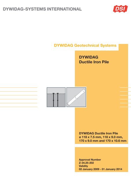
DIBTApproval Certificate Page 3 of 11 I January 2, 2009Z-<strong>34.25</strong>-<strong>202</strong>II. SPECIAL PROVISIONS1 Object of Approval and Application Range1.1 Object of ApprovalObject of this general approval are driven piles made of ductile cast iron tubes"DSI DUCTILE IRON PILE", Ø 118 x 7.5 mm, Ø 118 x 9.0 mm, Ø 118 x 10.6 mm,Ø 170 x 9.0 mm and Ø 170 x 10.6 mm by <strong>DYWIDAG</strong>-<strong>Systems</strong> International GmbH.<strong>Ductile</strong> cast iron piles are assembled tubes joined in partial lengths. The single tubes areconnected to each other by means of a special coupler splice or by special couplingelements designed for the cast iron pile.1.2 Area of ApplicationThe piles may only be loaded with predominantly static loads in accordance withDIN 1055-3 1 .The piles are designed for loading by axial compressive forces only. Their inclination tothe vertical may not exceed 45°, respectively 5° if piles with grouted sheathings are used.<strong>Pile</strong>s with grouted sheathings may only be used in non-cohesive or cohesive soils(definition according to DIN 1054 2 ).<strong>Pile</strong>s shall not be installed if the foundation soil contains ground water or seepage waterfrom waste heaps and/or landfills resulting in a high probability of steel corrosion in formof cavities and holes in accordance with DIN 50929-3 3 , Table 7, with W o < -8. In addition,in the case of piles without grouted sheathings, evidence shall be produced thatevaluation figure B 0 for a subsurface according to DIN 50 929-3, Table 2, is not smallerthan – 10.2 Provisions for the Product2.1 Properties and Composition2.1.1 General<strong>Pile</strong>s shall be made of spliced cast iron tubes. During or after placing into the soil, thecenter of the tubes shall be filled with cement grout (cf. section 2.1.3).2.1.2 Cast <strong>Iron</strong> Tubes and Splicing Sleeves, Quality and DimensionsThe following directional analysis shall be observed for the material:C approx. 3.7%, Si approx. 2.3%, Mn
DIBTApproval Certificate Page 4 of 11 I January 2, 2009Z-<strong>34.25</strong>-<strong>202</strong>The wall thicknesses indicated are minimum wall thicknesses that have to be obtained,allowing for tolerance.2.1.3 Cement groutCement grout fulfilling property class C 20/25 or C 25/30 according to DIN EN 206-1 5 inconjunction with DIN 1045-2 6 , sections 5.3.8 and 5.1.4 shall be used for the interior of ironpiles and for outer grout cover.2.1.4 Connection in the Foundation BodyThe load transfer from the cast iron tube into the foundation body is accomplished by aload distribution plate according to Appendix 1. To compensate a possible settlement ofthe concrete fill in the piling tube, the hollow space below the plate generated duringinstallation of the pile plate shall be filled with cement grout.2.2 Storage, Transport and Labelling2.2.1 Storage, TransportCast iron tubes shall be stored and transported such that damaging of the tube lengthscan be excluded.2.2.2 LabellingThe delivery note for the cast iron piles and splicing sleeves shall be marked with theconformity symbol by the manufacturer pursuant to the Conformity Symbol Ordinanceissued by the German States. Labelling may only be carried out when the requirementpursuant to Section 2.3 has been met. The following information must be included:- Object of approval with cross-sectional dimensions- Approval No.: Z-<strong>34.25</strong>-<strong>202</strong>- Fabricating plant- Monitored by: ………………2.3 Evidence of Conformity2.3.1 GeneralEvery fabricating plant must affirm conformity of the pile components to the provisions ofthis approval certificate by means of a certificate of conformity based on the regulationsdetailed in section 2.3.2.Conformity of “DSI <strong>Ductile</strong> <strong>Iron</strong> <strong>Pile</strong>s” to the provisions of this approval certificate must beconfirmed by means of a declaration of conformity based on the regulations detailed insection 2.3.3.2.3 Evidence of Conformity for <strong>Pile</strong> Components2.3.1 GeneralBased on an in-house production inspection and a regular external supervision includinga first testing, every fabricating plant must observe the following provisions to affirmconformity of the pile components in accordance with the provisions of this approvalcertificate.5 DIN EN 206-1:2001-07 Concrete – part 1: Specification, properties, production and conformityDIN EN 206-1/A1:2004-10 Concrete – part 1: Specification, properties, production and conformity; German version EN 206-1/A1:2004DIN EN 206-1/A2:2005-09 Concrete – part 1: Specification, properties, production and conformity; German version EN 206-1:2000/A2:20056 DIN 1045-2:2008-08 Bearing structures made of concrete, reinforced concrete and prestressed concrete – part 2:concrete -specification, properties, production and conformity -codes of practice for DIN EN 206-1
DIBTApproval Certificate Page 5 of 11 I January 2, 2009Z-<strong>34.25</strong>-<strong>202</strong>The manufacturer of cast iron tubes and splicing coupler shall commission a recognizedcertification institution to issue the certificate of conformity, as well as a recognizedinspection agency for external surveillance including product inspections.The certification institution shall submit a copy of the certificate of conformity issued to theGerman Institute for Civil Engineering for information.2.3.2.2 Internal Production ControlAn internal production control shall be established and implemented in every fabricatingplant. The term “internal production control” is defined as the continuous monitoring ofproduction by the manufacturer which ensures that the manufactured products complywith the provisions of this general approval.The internal production control must contain at least the measures detailed below.Cast <strong>Iron</strong> Tubes and splicing sleeves:The following directional analysis shall be observed for material:C approx. 3.7%, Si approx.2.3%, Mn
DIBTApproval Certificate Page 6 of 11 I January 2, 2009Z-<strong>34.25</strong>-<strong>202</strong>2.3.2.3 External SurveillanceThe internal production control in each fabricating plant shall be regularly checked by anexternal surveillance, but at least twice a year.A first testing shall be carried out as part of the external surveillance. Samples forsampling inspections shall be taken and the inspection tools controlled. Sampling andinspections are incumbent on the respective recognized inspection agency.The results of the certification and external surveillance shall be kept for at least fiveyears. On request, they shall be presented to the German Institute for Civil Engineeringand the responsible supreme construction supervision authority by the certificationinstitution or inspection agency.2.3.3 Evidence of conformity for “DSI <strong>Ductile</strong> <strong>Iron</strong> <strong>Pile</strong>”Based on inspections of accomplishment according to section 4.4, affirmation ofconformity of the “DSI <strong>Ductile</strong> <strong>Iron</strong> <strong>Pile</strong>” with the provisions of this approval certificatemust be given by means of a declaration of conformity by the acting company.3 Provisions for Planning and Design3.1 GeneralFor the planning and design of structures using “DSI <strong>Ductile</strong> <strong>Iron</strong> <strong>Pile</strong>s”, the followingprovisions apply.3.2 Evidence of Load Bearing Capacity3.2.1 Evidence of External Load Bearing CapacityEvidence of the external load capacity shall be produced by test loadings in accordancewith DIN 1054 2 or based on empirical values according to DIN 1054 2 , sections 8.4.4 andappendix C, following equation 3.1.E dR dR 1,kγ pR b1,kR s1,k= design value of individual pile load= design value of individual pile resistance= characteristic pile resistance for ultimate state GZ 1B= partial safety coefficient for pile pressure resistance based onempirical values according to DIN 1054 2 , table 3= characteristic pile foot resistance for ultimate state GZ 1B= characteristic pile sheathing resistance for ultimate state GZ 1BDue to their interior bearing capacity, test loads no higher than those according toequation 3.2 may be applied during test loading on structural piles.f t0.2kA t= strain at 0.2% elongation = 320 N/mm²= cross section of the ductile cast iron pileTable 1 lists the loads for the approved cross sections:
DIBTApproval Certificate Page 7 of 11 I January 2, 2009Z-<strong>34.25</strong>-<strong>202</strong>Table 1: Maximum design load during test loadingCast <strong>Iron</strong> Tube [mm]Ø 118 x 7.5Ø 118 x 9.0Ø 118 x 10.6Ø 170 x 9.0Ø 170 x 10.6Max. design load applied to structural pilesduring test loading750 kN890 kN1,030 kN1,310 kN1,520 kNIn the case of piles with grouted sheathings, test load can be increased by the percentageof the inner pile concrete.f ck (t) =characteristic value of concrete compressive strength against age of= cross section of inner pile concreteA Bconcrete tIn addition, a sufficient longitudinal shear resistance according to section 3.2.2.4 is to beensured during test loading in the case of grouted piles (skin friction piles).If proof of stability is to be given for the pile, the maximum design load for test loading is tobe determined according to section 3.2.2.3.3.2.2 Evidence of Internal Load Bearing Capacity3.2.2.1 GeneralEvidence of internal load bearing capacity includes- evidence of cross section load bearing capacity according to 3.2.2.2,- evidence of stability in the case of piles without lateral soil support according to3.2.2.3 and- evidence of bond joint load bearing capacity between grout cover and cast iron tube inthe case of grouted piles according to 3.2.2.4.Tube cross sections of piles without grouted sheathings are to be determined taking intoaccount a sacrificial corrosion of 3 mm of the external diameter.3.2.2.2 Evidence of Cross Section Load Bearing CapacityIf no evidence of stability is required, evidence must be given that the design value ofindividual pile stress E d does not exceed the design value of the pile’s cross section loadbearing capacity R i,d .The design value of the pile’s cross section load bearing capacity R i,d is composed of thesum of design values of structural element resistance of the cast iron tube and ofconcrete inside the tube, where only the concrete enclosed by the iron tube may be takeninto account even in the case of piles with grout cover.(3.5)γ MaR ckγ c= partial security coefficient for the cast iron tube= 1.10 for load cases LF 1 to LF 3= A B • f ck= partial security coefficient for concrete= 1.50 for load cases LF 1 and LF 2= 1.30 for load case LF 3
DIBTApproval Certificate Page 8 of 11 I January 2, 2009Z-<strong>34.25</strong>-<strong>202</strong>The design values R i,d for individual pile types can be taken from table 2 for load cases LF1 and LF 2.Table 2: Design Values R i,d of cross sectional load bearing capacity of piles withinterior cement grouting and concrete quality C20/25 and C25/30(load cases LF 1 and LF 2)Cast <strong>Iron</strong> Tube[mm]Without outer grouting,with Post Concrete FillingWith outer grouting(skin friction piles)C20/25 C25/30 C20/25 C25/30Ø 118 x 7.5 709 kN 737 kN 869 kN 896 kNØ 118 x 9.0 842 kN 868 kN 1,001 kN 1,027 kNØ 118 x 10.6 979 kN 1,003 kN 1,139 kN 1,163 kNØ 170 x 9.0 1,335 kN 1,396 kN 1,566 kN 1,627 kNØ 170 x 10.6 1,545 kN 1,603 kN 1,776 kN 1,834 kN3.2.2.3. Evidence of StabilityEvidence of stability must be given according to the theory of second order in accordancewith DIN 18800-5 8 without beginning of lateral support by the soil if a pile stands partlyfree, in organic (definition according to DIN 1054 2 ) or in cohesive soils (definitionaccording to DIN 1054 2 ) with an undrained shearing resistance of c u < 15 kN/m 2(according to DIN 18137-1 9 ). An unintended excentricity e v = L/150 needs to be taken intoaccount for this evidence, with L being the free, unsupported length of the pile.As when determining the cross section load bearing capacity, only the concrete enclosedby the cast iron tube may be taken into account.3.2.2.4 Evidence of longitudinal shear resistance of the bond joint between outer grouted coverand cast iron tubeAt the ultimate state of load bearing capacity, evidence needs to be given that the ratio ofthe design value of stress E v,d , which is to be transmitted via skin friction, does not exceedthe design value of stress of the bond joint between the cast iron tube and the grout coverR v,d .E d is the design value of the individual pile stress, R d is the design value of the pileresistance resulting from the exterior load bearing capacity according to 3.2.1 and R S,d isthe percentage of the design value R d that is transferred via skin friction. If the percentagecontact area R S,d of skin friction cannot be determined in cases of combined load transfervia tip pressure and skin friction, the equation E vd = E d applies.The design value of longitudinal shear resistance R v,d of the interior joint between the groutcover and the cast iron tube may be determined according to equation (3.8).d = nominal diameter of the cast iron tubeL eff = effective pile length without taking into account the coupling areasThe design value of the bond strength τ R,D of the joint between cast iron tube and groutedsheathing may be determined according to equation (3.9):8 DIN 18800-5:2007-03 Steel structures – part 5: bonded supporting structures consisting of steel and concrete – design andconstruction9 DIN 18137-1:1990-08 Foundation soil, tests and testing equipment; determination of shear strength; terms and basic test
DIBTApproval Certificate Page 9 of 11 I January 2, 2009Z-<strong>34.25</strong>-<strong>202</strong>τ R,k = basic value for bond stress using τ R,k = 0,32 N/mm²γ M,v = partial safetyfactor γ M,v = 2.1 for the load cases LF 1 and LF 2,1.8 for the load case LF 3μ k = friction coefficient between cast iron tube and the grout cover with μ k = 0.5σ h = lower characteristic value for the surface pressure actinghorizontally via the pile circumference consisting of earth pressureand interaction in N/mm²If more precise values are not given, a value ofυ ’τ M= friction angle of drained soil (effective friction angle)= skin friction of the joint concrete/soil when in useτ M = characteristic value of pile skin friction, determined via test loads orempirical values according to DIN 1054², table D.1γ Pc , γ P = partial security coefficient for pile load resistance of test loads orempirical values according to DIN 1054², tables 2 and 3may be assumed for σ h .3.2.2.5 Connections in the <strong>Pile</strong> Head (Appendix 1)The steel plate (Appendix 1) must be structurally connected to the cast iron tubes, withthe end of the upper tube having to be plane.Stresses in the pile head need to be verified according to DIN 1045-1 10 .4 Execution of the Installation4.1 Installing companyThe installation of “DSI <strong>Ductile</strong> <strong>Iron</strong> <strong>Pile</strong>s” in accordance with this approval certificate mayonly be executed under technical supervision of <strong>DYWIDAG</strong>-<strong>Systems</strong> International GmbH.The installation of “DSI <strong>Ductile</strong> <strong>Iron</strong> <strong>Pile</strong>s” may also be executed by companies able toproduce a current certificate of <strong>DYWIDAG</strong> <strong>Systems</strong> International GmbH stating that theyhave been trained extensively in the execution of “DSI <strong>Ductile</strong> <strong>Iron</strong> <strong>Pile</strong>s” in accordancewith this approval certificate issued on January 2 nd , 2009. The executing company has toproduce a declaration stating that the installed “DSI <strong>Ductile</strong> <strong>Iron</strong> <strong>Pile</strong>s” comply with therequirements of this approval certificate.4.2 Driving Works and <strong>Pile</strong> ArrangementDIN 4026 11 applies for pile driving. Each pile must be provided with a ram shoe. <strong>Pile</strong>smust be checked for straightness. The radius of curvature must measure at least 150 m;the measured value has to be given in the driving records. The interior of the tubes has tobe injected with cement grout (cf. section 2.1.3) during or after installation in the soil, alsocf. section 4.3.10 DIN 1045-1:2008-08 Supporting structures consisting of steel, reinforced concrete and prestressedconcrete – part 1: design and construction11 DIN 4026:1975-08 Driven piles – construction, design and admissible stress
DIBTApproval Certificate Page 10 of 11 I January 2, 2009Z-<strong>34.25</strong>-<strong>202</strong>With respect to the pile fabrication, the following imperfections are to be expected at thepile head:- Deviation of the pile head position: +/- 8 cm- Deviation from nominal deviation: +/- 3°The imperfections described above must be considered when calculating the constructionabove the pile foundation.The minimum center-to-center distances of the piles in the area of their load transmissionlengths are 0.5 m for cast iron piles Ø 118 mm and 0.7 m for cast iron piles Ø 170 mm.Their lengths in the stable foundation soil (load transmission lengths) must be > 3 m.Since the piles may not be damaged during driving, it may be necessary to cancel thedriving work before reaching the minimum load transmission lengths. The externalbearing capacity for these piles shall be verified by additional test loadings.This evidence is not required for plain end-bearing piles.To avoid bending strains of individual piles resulting from an unintentional off-centerloading, the piles shall be arranged such that such off-centricity can be regarded asharmless for the individual pile (e.g. at least 3 piles under a concentrated load or two pilerows under a line load or other suitable structural means which ensure that bendingstrains are avoided).4.3 Outer grout cover (skin friction)If the pile is realized with grout cover, the cast iron tubes have to be covered with acontinuous coating of cement mortar (cf. section 2.1.3) along their entire lengths.Cement mortar has to be continuously injected during driving through an injection valve atthe upper end of the cast iron tube into the annular space created by the ram shoe.The cement mortar flows out through a triangular opening (lateral lengths of approx. 10 to15 cm) that is located as near as possible to the bottom edge of the pile.The suspension level may not sink deeper than 0.5 m below ground. During installation,cement grout always has to flow out at the planned surface during pile driving works.During pile driving, driving time per length unit and driving resistance are to be recordedin writing. A ram shoe (grout shoe) according to appendix 2 must be used for piles withgrout cover. The lateral protrusion of the ram shoe has to ensure a hardened cementgrout covering of 20 mm minimum in the coupler area as well.Due to losses of cement mortar during of manufacturing, the effective spend of cementmortar has to be at least 10% higher than is theoretically required. The required amountof cement mortar must be assured by means of sufficient pump capacity against drivingtime per pile length. Losses of cement mortar must be recorded in writing and evaluated.4.4 Declaration of ConformityDuring the installation of “DSI <strong>Ductile</strong> <strong>Iron</strong> <strong>Pile</strong>s”, the orderly execution of the works mustbe recorded in writing by the site manager or his representative.Affirmation of conformity of “DSI <strong>Ductile</strong> <strong>Iron</strong> <strong>Pile</strong>s” with the regulations of this approvalcertificate has to be given for each installation by means of a declaration of conformity ofthe executing company based on controls of the execution (table 3) and on visualinspection to determine the correct condition of execution. The results of these controlsmust be recorded and evaluated.If test results are unsatisfactory, the manufacturer has to immediately take the necessarymeasures to eliminate the deficiency. Once the deficiency has been eliminated, the test inquestion must be repeated immediately, as far as this is technically possible andnecessary to prove that the deficiency has been eliminated.
DIBTApproval Certificate Page 11 of 11 I January 2, 2009Z-<strong>34.25</strong>-<strong>202</strong>Table 3:Measures for controlling installationTest Item Examination/ Inspection Minimum FrequencyCement mixturein the case of bagged cargo, theshipping note and imprints on bagshave to be checked. In the case ofsilo cargo, shipping note must bechecked.Cement mortar according to DIN EN 206-1 5 inconjunction with DIN 1045-2 6Cast iron tubes andconnecting couplersshipping note and inspectioncertificate checkeach deliveryevery 100 m³ 1 serieswith 3 test itemseach deliveryThe declaration of conformity of the executing company must contain at least thefollowing details:- Approval number- Name of the construction project- Date of installation- Name and registered office of the executing company- Confirmation of the execution according to planning documents- Documentation of source materials and shipping notes- Nature of inspections or tests- Date of inspection or test- Inspection and test results and comparison to the requirements, if applicable- Particularities- Name, company and signature of the person responsible for the inspections and testsRecords have to be available on site during time of construction. They have to be kept bythe company for at least five years after completion of construction work.Copies of the records must be handed out to the site manager for inclusion inconstruction files and must be presented to the German Institute for Civil Engineering andto the responsible building supervisory board on demand.HenningCertified
Austria<strong>DYWIDAG</strong>-<strong>Systems</strong> International GmbHAlfred-Wagner-Strasse 14061 Pasching/Linz, AustriaPhone +43-7229-610 49 0Fax +43-7229-610 49 80E-mail dsi-a@dywidag-systems.atwww.dywidag-systems.atBelgium and Luxembourg<strong>DYWIDAG</strong>-<strong>Systems</strong> International N.V.Industrieweg 253190 Boortmeerbeek, BelgiumPhone +32-16-60 77 60Fax +32-16-60 77 66E-mail info@dywidag.bewww.dywidag-systems.comFranceDSI-Artéon146 Avenue du BicentenaireZ.I. Dagneux01122 Montluel Cedex, FrancePhone +33-4-78 79 27 82Fax +33-4-78 79 01 56E-mail dsi.france@dywidag.frwww.dywidag-systems.frGermany<strong>DYWIDAG</strong>-<strong>Systems</strong> International GmbHSchuetzenstrasse 2014641 Nauen, GermanyPhone +49-3321-44 18 0Fax +49-3321-44 18 38E-mail suspa@dywidag-systems.comwww.dywidag-systems.de<strong>DYWIDAG</strong>-<strong>Systems</strong> International GmbHMax-Planck-Ring 140764 Langenfeld, GermanyPhone +49-2173-79 02 0Fax +49-2173-79 02 20E-mail suspa@dywidag-systems.comwww.dywidag-systems.de<strong>DYWIDAG</strong>-<strong>Systems</strong> International GmbHGermanenstrasse 886343 Koenigsbrunn, GermanyPhone +49-8231-96 07 0Fax +49-8231-96 07 40E-mail suspa@dywidag-systems.comwww.dywidag-systems.de<strong>DYWIDAG</strong>-<strong>Systems</strong> International GmbHSiemensstrasse 885716 Unterschleissheim, GermanyPhone +49-89-30 90 50 100Fax +49-89-30 90 50 120E-mail dsihv@dywidag-systems.comwww.dywidag-systems.comItalyDYWIT S.P.A.Via Grandi, 6420017 Mazzo di Rho (Milano), ItalyPhone +39-02-934 68 71Fax +39-02-934 68 73 01E-mail info@dywit.itwww.dywit.itNetherlands<strong>DYWIDAG</strong>-<strong>Systems</strong> International B.V.Veilingweg 25301 KM Zaltbommel, NetherlandsPhone +31-418-57 89 22Fax +31-418-51 30 12E-mail email@dsi-nl.nlwww.dywidag-systems.comNorway<strong>DYWIDAG</strong>-<strong>Systems</strong> International ASIndustrieveien 7A1483 Skytta, NorwayPhone +47-67-06 15 60Fax +47-67-06 15 59E-mail adm@dsi-dywidag.nowww.dywidag-systems.comPoland<strong>DYWIDAG</strong>-<strong>Systems</strong> International Sp. z o.o.ul. Przywidzka 4/6880-174 Gdansk, PolandPhone +48-58-300 13 53Fax +48-58-300 13 54E-mail dsi-polska@dywidag-systems.comwww.dywidag-systems.plSpain<strong>DYWIDAG</strong> Sistemas Constructivos, S.A.Avd/de la Industria, 4Pol. Ind. la Cantuena28947 Fuenlabrada (Madrid), SpainPhone +34-91-642 20 72Fax +34-91-642 27 10E-mail dywidag@dywidag-sistemas.comwww.dywidag-sistemas.comUnited Kingdom<strong>DYWIDAG</strong>-<strong>Systems</strong> International Ltd.Northfield RoadSoutham, WarwickshireCV47 0FG, Great BritainPhone +44-1926-81 39 80Fax +44-1926-81 38 17E-mail sales@dywidag.co.ukwww.dywidag-systems.com/ukAustriaArgentinaAustraliabelgiumBosnia and herzegovinaBrazilCanadaChileColombiaCosta RicaCroatiaCzech republicDenmarkEgyptestoniaFinlandFranceGermanyGreeceGUATEMALAHONDURASHong KongIndonesiaItalyJapanKoreaLebanonLuxembourgMalaysiaMexicoNetherlandsNorwayOmanPanamaParaguayPeruPOLANDPortugalQatarSaudi ArabiasingaporeSouth AfricaSpainSwedenSwitzerlandTaiwanThailandTurkeyUnited Arab EmiratesUnited kingdomUruguayUSAVenezuelawww.dywidag-systems.com