
You also want an ePaper? Increase the reach of your titles
YUMPU automatically turns print PDFs into web optimized ePapers that Google loves.
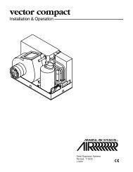
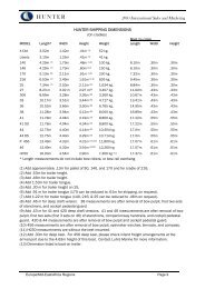
<strong>Model</strong> <strong>37010</strong>-<strong>Series</strong>ELECTRIC MARINE TOILETPush Button OperationFEATURES• White Vitreous China Bowl Available in Two Sizes• Baked Enamel Seat & Cover in Compact orHousehold Size• Flexible Impeller Flush Pump• Permanent Magnet Type Motor, Fully Enclosed, withStainless Steel Shaft• High Capacity Macerator and Bowl Scavenger Pump• Built-in Back Flow Preventer• All Corrosion Resistant Material for Marine UseVARIATIONSVOLTAGE COMPACT SIZE HOUSEHOLD SIZE12 Vdc <strong>37010</strong>-0000 <strong>37010</strong>-100012 Vdc EMC <strong>37010</strong>-0090 <strong>37010</strong>-109024 Vdc <strong>37010</strong>-0006 <strong>37010</strong>-100624 Vdc EMC <strong>37010</strong>-0096 <strong>37010</strong>-109632 Vdc <strong>37010</strong>-0003 <strong>37010</strong>-1003INSTALLATIONThe Jabsco electric toilet may be installed above or belowthe waterline. Flush pump is self-priming with a vertical liftup to 4 feet; discharge macerator pump can operateagainst a vertical head up to 4 feet.Inlet and outlet seacocks should be easily accessible andbe positive shut off valves. If seacocks cannot be convenientlyoperated from toilet location, install suitable shut offvalves for inlet and discharge connections.Base assembly may be moved 90° to accommodate connectionsand provide accessibility for servicing.Surface where toilet is mounted should be flat to preventdistortion of toilet base.PLUMBING CONNECTIONS - Connect inlet hose usingeither 5/8" or 3/4" ID hose (a sleeve is included to adaptpump inlet from 5/8" to 3/4"). Make sure all inlet connectionsare airtight and free of sharp bends or restrictions.Connect 1" or 1-1/2" hose to discharge port (Adaptor98023-0080 is included to convert discharge port to 1-1/2"ID hose), and make suitable connection to holding tank orother discharge system. Avoid sharp bends or restrictions.For above waterline installations, a check valve may haveto be installed in the flush water intake line to ensure rapidpump priming. To retain water in bowl, make a loop in thedischarge line about 8 inches above base of bowl.!WARNINGFlood hazard. If toilet is installed below thewaterline or may be below the waterline at anyangle of heel or trim, it must be installed withproperly positioned vented loops. Failure to doso can result in flooding which can cause lossof property and life.<strong>Model</strong> <strong>37010</strong>-<strong>Series</strong>! CAUTION Do not connect the toilet to the vesselspotable water for its source of supply. To do so can result incontamination of potable water supply. If fresh water is preferredfor flushing, provide a separate fresh water tank tosupply water to the toilet only.DO NOT CONNECT INLET HOSE TO A PRESSURIZEDWATER SYSTEM.If the toilet is, or can be, below waterline at any normal(including static) attitude of vessel heel and/or trim, a 3/4"Vented Loop Fitting must be installed in the length of hoseconnecting the flushing pump to the inlet seacock. TheVented Loop Fitting must be positioned so it remains slightly*above the waterline at all angles of heel and trim.In some installations when a vented loop is installed in theintake hose, the flushing pump primeability and flow characteristicsare reduced and may adversely affect toiletfunction.To restore pump performance, connect a solenoidvalve (Jabsco No. 37068-0000) to the vent air inlet to interruptthe air supply during the flush cycle. The brass port ofthe solenoid valve (remove plastic filter if attached) shouldbe connected to the vent inlet with 3/16" hose and thesolenoid wired in parallel with the toilet motor. SeeDiagram 1 for installation and wiring illustration.* Recommended minimum height above waterline is 6".
ELECTRICAL CONNECTIONS - Select a location for theswitch and instruction plate, making sure wire leads fromboth the toilet and power source can be routed to theswitch. Ensure the panel where installing switch is nomore than 1" thick. Drill a 5/8" mounting hole and installswitch and instruction plate. Use stranded copper wire ofthe correct size (determined from the electrical specificationschart) to connect one side of the switch to the positivepower source. An appropriate size fuse or equivalentcircuit breaker (determined from electrical specificationschart) must be installed in the positive power lead withinseven inches of the power source. Connect the other sideof the switch to the orange (positive) motor lead. Connectthe black (negative) motor lead to the negative side of thebattery or grounded buss bar.NOTICE: Correct motor polarity (orange to positive, blackto negative) is important. Reverse polarity can damagemotor and void warranty. Full voltage at the motor isrequired to properly operate the Electric Toilet. The toiletmust be wired in a circuit independent of all other accessories.ELECTRICAL SPECIFICATIONSAMP FUSE WIRE SIZE PER FEET OF RUN*VOLTAGE DRAW SIZE 0'-10' 10'-15' 15'-25' 25'-40' 40'-60'12 Vdc 16 25 #12 #10 #10 #8 #624 Vdc 8 15 #16 #14 #12 #10 #1032 Vdc 6 10 #16 #16 #14 #14 #12* Length of run is total distance from power source to product and back to ground.OPERATING INSTRUCTIONSMake sure inlet and outlet seacocks are all open; push buttonto operate. Operate until bowl is completely flushed anddischarge pump has scavenged water from bottom of bowl.The Jabsco electric marine toilet will provide years of troublefreeservice if properly used. It will handle waste and toilettissue. It will NOT handle rags, sanitary napkins or hardsolid objects.If bowl does not pump out and begins to fill, partially closeinlet valve until bowl is cleared and completely pumped out.Then operate for a few seconds with both valves open toclear entire toilet and discharge system. For maximumsafety, when toilet is not in use or vessel is unattended,close both the inlet and discharge seacocks.To drain for winter lay-up, close inlet valve and operate fora few seconds until all water is pumped out.After long periods of non-use, toilet and pump may dry out.To ease initial start-up, put about one quart of water in bowland let stand awhile before initial use.DISASSEMBLY!WARNINGFlood hazard. Close inlet and outletseacocks prior to disassembling toilet.Failure to do so can result in floodingwhich can cause loss of property and life.Disconnect pumping inlet and discharge hoses. Removefour screws, Key No. 25, pull out complete motor, pump andmacerator assembly. If assembly does not slide out easily,push forward and pull back sharply several times to freemacerator housing from base.Remove discharge port, Key No. 12, and joker valve.Unscrew chopper plate, Key No. 14, by turning counterclockwise,facing plate. Prevent shaft from turning by placingscrewdriver in discharge port and locking centrifugalimpeller blade. Remove macerator housing. Loosenimpeller set screw and slide impeller off motor shaft.Remove four flathead screws and two washers, Key Nos.20, 21, & 22. Remove the plastic wearplate, Key No. 23,with sealing sleeve, Key No. 19, and gasket, Key No. 26.Slide pump assembly off motor shaft. Replace all worn ordamaged parts, clean remaining parts.ASSEMBLYPress seal into body with lip facing impeller; be carefulnot to cock seal in bore. Install pump body on motor andposition on register. Lubricate impeller bore with pumpgrease and install impeller. Position the gasket againstthe body and install the wearplate ensuring the two plasticsealing washers are under the heads of the top andbottom screws. NOTE: The current plastic wearplatesupercedes the earlier brass wearplate and with it thestainless steel wearplate is no longer used. Slide the rubbersealing sleeve on the motor shaft and push it into itsrecess in the wearplate. Relocate centrifugal impeller onshaft, about 1/8" from the wearplate, and tighten setscrew. Place macerator housing over shaft and centrifugalimpeller, put lock washer on end of shaft and screwchopper plate on shaft and tighten. Install O-ring in O-ring groove in wearplate surface, a little grease will helphold in place, make sure inside body surfaces are clean,line up slot in base with key on macerator housing, slidepump assembly into base and tighten with the fourscrews. Turn motor on for one or two seconds to be surecentrifugal impeller is free.TONEGATIVETOPOSITIVETONEGATIVEDISCHARGE TOHOLDING TANKMOUNTINGBRACKETVENT TOATMOSPHERE37068-0000SOLENOIDELECTRICALCONNECTIONSPUSH BUTTONSWITCHTO VENTEDLOOPVENTEDLOOPVIEW AVIEW AINLETWATERLINE
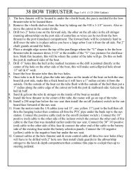
DIMENSIONAL DRAWINGINCHES (MILLIMETRES)FEGD Overall WidthC2 Leads — 11 Long(279)5/8 Dia2 Places (16)5/16(8) 3-1/8(79)1 Dia(25)12-15/16B4(102)6 (152)10-7/8A3-1/2(89)3-7/8(98)7-3/8(187)2-1/2(64)MOTOR COVER4(102) 5-3/8(137)5/8(16)A B C D E F GCOMPACT SIZE BOWL 19-3/4 (493) 4-13/16 (123) 13-13/16 (351) 13-7/8 (352) 17-3/4 (451) 9-7/8 (251) 7-5/8 (194)HOUSEHOLD SIZE BOWL 21-3/4 (543) 5-11/16 (148) 14-5/8 (372) 14-3/4 (375) 19-3/4 (502) 11-1/4 (286) 8-1/2 (216)U.S.A.Jabsco1485 Dale Way, P.O.Box 2158Costa Mesa, CA 92628-2158Tel: (714) 545-8251Fax: (714) 957-0609UNITED KINGDOMJabscoBingley Road, HoddesdonHertfordshire EN11 OBUTel: +44 (0) 1992 450145Fax: +44 (0) 1992 467132CANADAFluid Products Canada55 Royal RoadGuelph, Ontario N1H 1T1Tel: (519) 821 -1900Fax: (519) 821-2569THE PRODUCTS DESCRIBED HEREIN ARE SUBJECT TOTHE JABSCO ONE YEAR LIMITED WARRANTY, WHICHIS AVAILABLE FOR YOUR INSPECTION UPON REQUEST.JAPANNHK Jabsco Company Ltd.3-21-10, Shin-YokohamaKohoku-Ku, Yokohama, 222Tel: 045-4758906Fax: 045-475-8908GERMANYJabsco GmbHOststrasse 2822844 NorderstedtTel: +49-40-53 53 73 -0Fax: +49-40-53 53 73 -11© Copyright 2000, ITT Industries Printed in U.S.A. All Rights Reserved Form: 43000-0612 Rev. 4/2000