CFRP Strand Application on Penobscot Narrows Cable Stayed Bridge
CFRP Strand Application on Penobscot Narrows Cable Stayed Bridge
CFRP Strand Application on Penobscot Narrows Cable Stayed Bridge

Create successful ePaper yourself
Turn your PDF publications into a flip-book with our unique Google optimized e-Paper software.
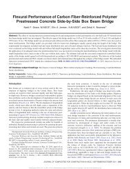
Rohleder, Jr., P.E., S.E., W. Jay Page 2<str<strong>on</strong>g>CFRP</str<strong>on</strong>g> <str<strong>on</strong>g>Strand</str<strong>on</strong>g> <str<strong>on</strong>g>Applicati<strong>on</strong></str<strong>on</strong>g> <strong>on</strong> <strong>Penobscot</strong> <strong>Narrows</strong> <strong>Cable</strong> <strong>Stayed</strong> <strong>Bridge</strong>ABSTRACTMaine’s first cable stayed bridge opened to traffic <strong>on</strong> December 30, 2006. Designed as an emergency replacementfor the Waldo Hancock <strong>Bridge</strong>, the new bridge uses an innovative cradle system to carry the stays from bridge deckthrough the pyl<strong>on</strong> and back to the bridge deck. Each strand is anchored independently, thus strands may beremoved, inspected and replaced while the bridge carries traffic. This advantage, coupled with Maine DOTc<strong>on</strong>cerns over the premature loss of the Waldo Hancock <strong>Bridge</strong> due to corrosi<strong>on</strong>, provided the interest in anopportunity to install and m<strong>on</strong>itor representative carb<strong>on</strong> fiber reinforced polymer (<str<strong>on</strong>g>CFRP</str<strong>on</strong>g>) strands in the cable staysof this bridge. <str<strong>on</strong>g>CFRP</str<strong>on</strong>g> strands were installed for purposes of assessing performance in a service c<strong>on</strong>diti<strong>on</strong> andevaluati<strong>on</strong> for use <strong>on</strong> future bridges. Three representative stays in the bridge were designed to include two referencestrands each, which may be removed and not replaced, without change to the bridge’s structural integrity. Six epoxycoated steel strands were removed and successfully replaced with <str<strong>on</strong>g>CFRP</str<strong>on</strong>g> strands in June 2007. Data is beingcollected from the m<strong>on</strong>itoring equipment installed <strong>on</strong> all of the strands (both traditi<strong>on</strong>al steel and <str<strong>on</strong>g>CFRP</str<strong>on</strong>g> strands) inthe bridge to evaluate <str<strong>on</strong>g>CFRP</str<strong>on</strong>g> strand performance for future bridge cable stay and post-tensi<strong>on</strong>ing installati<strong>on</strong>s. Thebridge locati<strong>on</strong> ensures that the test strands will be evaluated under a wide range of temperatures and variety of windloads.
Rohleder, Jr., P.E., S.E., W. Jay Page 3CFCC <str<strong>on</strong>g>Strand</str<strong>on</strong>g> <str<strong>on</strong>g>Applicati<strong>on</strong></str<strong>on</strong>g> <strong>on</strong> <strong>Penobscot</strong> <strong>Narrows</strong> <strong>Cable</strong> <strong>Stayed</strong> <strong>Bridge</strong>PROJECT BACKGROUNDThe opportunity for incorporating carb<strong>on</strong> fiber reinforced polymer (<str<strong>on</strong>g>CFRP</str<strong>on</strong>g>) cable strands into a new cablestay bridge in Maine started in July 2003 when the Maine Department of Transportati<strong>on</strong> awarded a c<strong>on</strong>tract forrenovati<strong>on</strong> of the 75-year old Waldo-Hancock (steel suspensi<strong>on</strong>) <strong>Bridge</strong>. Based <strong>on</strong> the Maine Department ofTransportati<strong>on</strong> inspecti<strong>on</strong> program, c<strong>on</strong>firmed by a minor exploratory opening of the main cables, the Department’sadvisor theorized that the main suspensi<strong>on</strong> cable was structurally intact. However, as work progressed and the cablewas progressively unwrapped, it became evident a c<strong>on</strong>siderable amount of corrosi<strong>on</strong> had taken its toll <strong>on</strong> the bridge.The bridge was immediately posted and extensive steps taken to reduce the superstructure weight and strengthen thebridge by adding supplemental cables to reduce the load <strong>on</strong> the corroded main cables. Simultaneously, planning anddesign started for a replacement structure (Figure 1), given that the strengthening project success was not assuredand that any immediate success could add <strong>on</strong>ly a limited number of years to the existing suspensi<strong>on</strong> bridge’s servicelife.The Maine Department of Transportati<strong>on</strong> quickly c<strong>on</strong>tracted with FIGG, from a field of 14 interestedteams, as designer of the new bridge and initiated an ‘owner-facilitated’ design/build process to quickly deliver thenew bridge. Design decisi<strong>on</strong>s were made rapidly, while involving the public in evolving the bridge aestheticelements. The optimum new structure was identified as a 2,120’ (646M) cable stayed bridge with a main spanlength of 1,161’ (354M). By fall, just six m<strong>on</strong>ths later, the Maine Department of Transportati<strong>on</strong> had negotiated astaged c<strong>on</strong>tract for c<strong>on</strong>structi<strong>on</strong> with Cianbro/Reed & Reed, LLC, a joint venture of the state’s two largestc<strong>on</strong>tractors and ground was broken <strong>on</strong> December 3, 2003.FIGURE 1 – <strong>Penobscot</strong> <strong>Narrows</strong> <strong>Bridge</strong> Elevati<strong>on</strong> View.CABLE STAY SYSTEM BACKGROUNDAs the new cable stay bridge design rapidly progressed, there was extensive discussi<strong>on</strong> am<strong>on</strong>g the owner,c<strong>on</strong>tracting team and FIGG <strong>on</strong> details of the cable stay system. FIGG had worked with Ohio Department ofTransportati<strong>on</strong> and the Federal Highway Administrati<strong>on</strong> to complete testing and receive approval in 2001 forinstalling the cradle system in a new cable stayed bridge, the I-280 Veterans’ Glass City Skyway in Toledo, Ohio.The Maine Department of Transportati<strong>on</strong> elected to also use the cradle system, recognizing the advantages of l<strong>on</strong>gterm durability and ease of maintenance. Given Maine’s recent history with cable c<strong>on</strong>diti<strong>on</strong>s, c<strong>on</strong>siderable effortswere directed toward developing a new cable stay system that prevented any opportunity for corrosi<strong>on</strong>. Thepatented (U.S. 6,880,193; 4-19-05) new cradle that housed individual stay strands was seen as a significant means tohelp accomplish this goal.
Rohleder, Jr., P.E., S.E., W. Jay Page 4With the cradle design, cable stay strands serve as tensile elements that are individually threadedc<strong>on</strong>tinuously from an anchorage at the bridge deck (see Figure 2), through a free length of HDPE external sheath(see Figure 3), through the cradle in the pyl<strong>on</strong> (see Figure 4) and back through another sheath and anchorage atbridge deck <strong>on</strong> the opposite side of the pyl<strong>on</strong>.FIGURE 2 – <strong>Cable</strong> Stay Block for Anchoring Individual <str<strong>on</strong>g>Strand</str<strong>on</strong>g>s Inside the Box Girder.FIGURE 3 – <strong>Cable</strong> Stay Sheath C<strong>on</strong>taining Individual <str<strong>on</strong>g>Strand</str<strong>on</strong>g>s.
Rohleder, Jr., P.E., S.E., W. Jay Page 5Locati<strong>on</strong> of CradleEmbedded in thePyl<strong>on</strong> WallFIGURE 4 – <strong>Cable</strong> Stay Cradle Locati<strong>on</strong>FIGURE 5 – <strong>Cable</strong> Stay Cradle Pipes Prior to Installati<strong>on</strong>.
Rohleder, Jr., P.E., S.E., W. Jay Page 7equipment allows for the selective replacement of steel strands with <str<strong>on</strong>g>CFRP</str<strong>on</strong>g> strands. The bridge locati<strong>on</strong> in coastalMaine provides a wide array of weather c<strong>on</strong>diti<strong>on</strong>s for a testing opportunity that includes large temperaturevariati<strong>on</strong>s and high humidity in a brackish water envir<strong>on</strong>ment. Testing of <str<strong>on</strong>g>CFRP</str<strong>on</strong>g> strands under these actual servicec<strong>on</strong>diti<strong>on</strong>s could be accomplished with a reas<strong>on</strong>able effort that could serve as a “Living Laboratory.” Financialsupport was provided by the FHWA and the State of Maine using federal Innovative <strong>Bridge</strong> Research andDeployment program funds for the <str<strong>on</strong>g>CFRP</str<strong>on</strong>g> applicati<strong>on</strong>s.Maine DOT with FHWA, FIGG and Lawrence Technological University collaborated to develop thedesign details for incorporating <str<strong>on</strong>g>CFRP</str<strong>on</strong>g> strands into the bridge as special reference strands. One of the key challengeswas devising the method for anchoring these cable strands within the already designed and fabricated cable stayanchorage system for this bridge. This included developing the specific hardware for installing the strands and thentransferring the stressing force directly from the strand into the stay anchor. The design team was interested inselecting a representative number of strands to replace with <str<strong>on</strong>g>CFRP</str<strong>on</strong>g> that would serve as a comprehensivedem<strong>on</strong>strati<strong>on</strong> at the least possible additi<strong>on</strong>al cost. Within this guideline, it was decided that we would replace tworeference strands in a short, medium and l<strong>on</strong>g stay. Variati<strong>on</strong>s in structural resp<strong>on</strong>se due to thermal effects, initialversus l<strong>on</strong>g-term bridge stresses and flexibilities in the overall bridge system would be captured by testing a shortand l<strong>on</strong>g stay with the middle stay serving as an average representati<strong>on</strong>. Additi<strong>on</strong>al selecti<strong>on</strong> criteria includedproximity to the existing data logger, utilizing stays with symmetrical strand patterns that worked best for design ofthe permanent anchor chairs, and coordinati<strong>on</strong> with c<strong>on</strong>current final stay c<strong>on</strong>structi<strong>on</strong> activities. Of the 20 possiblestays, the design team selected Stay 2 (short), 10 (average) and 17 (l<strong>on</strong>g) through the Western (observatory) Pyl<strong>on</strong>as the representative stays for carb<strong>on</strong> fiber strand installati<strong>on</strong> as shown in Figure 7. .The fast-tracked bridge c<strong>on</strong>structi<strong>on</strong> was completed with traditi<strong>on</strong>al epoxy coated steel strands installed inthe stays and the bridge opened to traffic <strong>on</strong> December 30, 2006, just 42 m<strong>on</strong>ths after identifying the need for anemergency bridge replacement. In June 2007, <strong>on</strong> the heels of a day l<strong>on</strong>g festival celebrating the bridge, six steelstrands (two each in three stays – short, medium and l<strong>on</strong>g) were removed and installati<strong>on</strong> of the <str<strong>on</strong>g>CFRP</str<strong>on</strong>g> strandssuccessfully completed – while the bridge c<strong>on</strong>tinued to carry traffic. The <str<strong>on</strong>g>CFRP</str<strong>on</strong>g> strands will be m<strong>on</strong>itoredindefinitely and inspected over time to evaluate the structural behavior and l<strong>on</strong>g term durability as it relates to usingthe <str<strong>on</strong>g>CFRP</str<strong>on</strong>g> materials for many more future applicati<strong>on</strong>s in l<strong>on</strong>g span bridge designs throughout the United States.FIGURE 7 – Locati<strong>on</strong> of Stays C<strong>on</strong>taining Experimental <str<strong>on</strong>g>CFRP</str<strong>on</strong>g> <str<strong>on</strong>g>Strand</str<strong>on</strong>g>s.
Rohleder, Jr., P.E., S.E., W. Jay Page 8The University of Maine c<strong>on</strong>tributed to the project with lab testing and calibrati<strong>on</strong> of load cells and fiber opticsensors that are measuring forces <strong>on</strong> the <str<strong>on</strong>g>CFRP</str<strong>on</strong>g> strands. They also proof tested the permanent anchor chairs andtemporary stressing chairs. They will also provide l<strong>on</strong>g term data collecti<strong>on</strong> of forces, strains and temperatures <strong>on</strong>these innovative <str<strong>on</strong>g>CFRP</str<strong>on</strong>g> strands. The collected data will be analyzed by the design team to compare results withexpected structural performance criteria for the <str<strong>on</strong>g>CFRP</str<strong>on</strong>g> and relative to the adjacent high-strength steel strands. Thecomparative performance criteria will include data such as initial prestressing el<strong>on</strong>gati<strong>on</strong>s, force losses, and anchorset values al<strong>on</strong>g with l<strong>on</strong>g term expected design strand prestressing forces related to time dependent properties andthermal effects experienced by the bridge.BACKGROUND OF PREVIOUS CFCC USE IN VEHICULAR BRIDGESCurrently, advanced fiber reinforced polymer (FRP) materials find worldwide applicati<strong>on</strong> in thec<strong>on</strong>structi<strong>on</strong> of small and large structures 1-5 such as beams and bridges. However, prestressed c<strong>on</strong>crete bridgesc<strong>on</strong>structed using CFCC reinforced polymer (<str<strong>on</strong>g>CFRP</str<strong>on</strong>g>) tend<strong>on</strong>s are few in number 1-6 . The FRP is a linearly elasticmaterial which may not provide a ductile failure mode like steel, however a structural member that is prestressedand reinforced with CFCC can be designed to fail in a similar ductile manner as under-reinforced c<strong>on</strong>crete members.The results of early research investigati<strong>on</strong>s 6-10 c<strong>on</strong>ducted in the Center for Innovative Materials Research atLawrence Technological University, Southfield, Michigan have shown that internally b<strong>on</strong>ded <str<strong>on</strong>g>CFRP</str<strong>on</strong>g> tend<strong>on</strong>s incombinati<strong>on</strong> with externally unb<strong>on</strong>ded <str<strong>on</strong>g>CFRP</str<strong>on</strong>g> tend<strong>on</strong>s can lead to reas<strong>on</strong>ably ductile simply supported 6,7 andc<strong>on</strong>tinuous 9,14 prestressed c<strong>on</strong>crete bridge systems. These results formulated the basis for design of the <strong>Bridge</strong>Street <strong>Bridge</strong> 11, located in Southfield, Michigan. The <strong>Bridge</strong> Street <strong>Bridge</strong> is the most recent <str<strong>on</strong>g>CFRP</str<strong>on</strong>g> prestressedc<strong>on</strong>crete bridge in the USA and the first to use CFRLeadline TM tend<strong>on</strong>s, CFCC TM strands, and <str<strong>on</strong>g>CFRP</str<strong>on</strong>g> NEFMAC TM1The <strong>Bridge</strong> Street <strong>Bridge</strong> served as a resource during development of the <strong>Penobscot</strong> <strong>Narrows</strong> <strong>Bridge</strong> <str<strong>on</strong>g>CFRP</str<strong>on</strong>g>strand installati<strong>on</strong> methods, details and material specificati<strong>on</strong>s.PROJECT <str<strong>on</strong>g>CFRP</str<strong>on</strong>g> MATERIAL QUALITITES AND CHARACTERISTICSThe specific <str<strong>on</strong>g>CFRP</str<strong>on</strong>g> material used for the <strong>Penobscot</strong> <strong>Narrows</strong> <strong>Bridge</strong> project is CFCC TM strand that isproduced by the Tokyo Rope Mfg. Co., Ltd. It comes in a variety of sizes, from 0.20" diameter single wire to 37individual helically wound wires with a total nominal diameter of 1.57". The actual CFCC TM strand used for the<strong>Penobscot</strong> <strong>Narrows</strong> <strong>Bridge</strong> cable stay test project is a 0.60" diameter, 7 wire strand, with 6 wires helically woundaround a center king wire. There is also a protective coating al<strong>on</strong>g the outside of the strand to shield the fibers fromnormal handling and exposure. The properties from the certificati<strong>on</strong> tests of the producti<strong>on</strong> strands used for thisproject are shown in Table 1. Note that the tensile rigidity for CFCC as included in Table 1 is defined as the slopeof a load-strain curve derived from the tensile tests. The CFCC tensile rigidity is the average value of results fromthe 20 test pieces from the load-strain curve obtained in accordance with a tensile test at 20% and 60% of theguaranteed tensile capacity.While the <str<strong>on</strong>g>CFRP</str<strong>on</strong>g> strand is similar in size to the steel strand, there are some significant material property differences.Due to the smaller effective cross secti<strong>on</strong>al area and modulus of the <str<strong>on</strong>g>CFRP</str<strong>on</strong>g> strand, the el<strong>on</strong>gati<strong>on</strong>s are approximately1.73 times that of the steel strand used for this project. The stress-stain relati<strong>on</strong>ship of the <str<strong>on</strong>g>CFRP</str<strong>on</strong>g> strand is also linearup to ultimate loading. Thus, there is no ductility within the strand. Compared to steel the <str<strong>on</strong>g>CFRP</str<strong>on</strong>g> strand isapproximately 5 times lighter, which makes handling and installati<strong>on</strong> easier. The shear resistance for the carb<strong>on</strong>fiber reinforced polymer cable material is negligible; therefore precauti<strong>on</strong>s need to be taken to avoid applying anytransverse forces <strong>on</strong> the cable.Since there are no anchorages within the pyl<strong>on</strong>s, the fricti<strong>on</strong> between the strands and the cradle sleeves isan important design parameter. The actual fricti<strong>on</strong> coefficient was measured in the laboratory during thepreliminary design phase for the steel strand and before installati<strong>on</strong> for the CFCC strand. The fricti<strong>on</strong> coefficientmeasured for the steel strand is 0.5 while the CFCC strand value is 0.3. While this decrease in fricti<strong>on</strong> for thereplaced strands do not affect the behavior of the <strong>Penobscot</strong> <strong>Narrows</strong> <strong>Bridge</strong>, this property would have to bec<strong>on</strong>sidered for a stay completely c<strong>on</strong>structed using <str<strong>on</strong>g>CFRP</str<strong>on</strong>g> strands or any other prestressing applicati<strong>on</strong>s whichexperience fricti<strong>on</strong> resistance.
Rohleder, Jr., P.E., S.E., W. Jay Page 9Similar to c<strong>on</strong>venti<strong>on</strong>al steel prestressing, care must be utilized during handling of <str<strong>on</strong>g>CFRP</str<strong>on</strong>g> strands.Excessive bending, abrasi<strong>on</strong>, shearing, crushing, or heat will damage the <str<strong>on</strong>g>CFRP</str<strong>on</strong>g> strand. In general, the <str<strong>on</strong>g>CFRP</str<strong>on</strong>g> strandis more susceptible to damage than the steel strand, thus additi<strong>on</strong>al care is required during installati<strong>on</strong>. It was alsoimportant to avoid twisting of the <str<strong>on</strong>g>CFRP</str<strong>on</strong>g> strand al<strong>on</strong>g its axis during installati<strong>on</strong>.CFCC TM QUALITY REPORTMessrs.Maine DOT <strong>Penobscot</strong> <strong>Narrows</strong> <strong>Bridge</strong> & ObservatoryC<strong>on</strong>figurati<strong>on</strong> CFCC 1×7 15.2φReport No.TEST-0890Date Sep. 29, 2006UnitSpecificati<strong>on</strong>Test resultsItem(metric) Nominal(metric)English (metric) ToleranceEnglishEnglishLot No. - - - 1166 (d) 1168 (e)Diameter(mm)In.(15.2)0.60Effective cross secti<strong>on</strong>al area (mm 2 ) (113.6)In 2 0.176Pitch(mm)In.-Linear density(g/m) (226)lb/ft 0.15Breaking load(kN)kipsTensile strength (kN/mm 2 )ksiTensile rigidity(kN)kips(199)44.8(1.75)254(15,600)3,510-Ave. (15.5)0.61(15.4)0.61- - - ---(199) orabove(1.87) orabove (a)(14,500~17,500)Tensile modulus (kN/mm 2 ) (137) (127~153)ksi 19,887(b)El<strong>on</strong>gati<strong>on</strong> at break % 1.5 1.2 orabove (c)1 MPa = 0.145 ksi; 1 kN = 0.225 kips; 1 g/m = 0.000672 lb/ft; 1 in. = 25.4 mmAve. (193)7.6Ave. (225)0.15Ave. (246)55.3Max. (259)58.3Min. (232)52.2Ave. (2.20)319Ave. (15,980)3,596Ave. (141)20,468(190)7.5(222)0.15(241)54.2(250)56.2(234)52.7(2.10)305(16,160)3,636(142)20,613Ave. 1.5 1.5(a) Tensile strength = Breaking load / Effective cross secti<strong>on</strong>al area(b) Tensile modulus = Tensile rigidity / Effective cross secti<strong>on</strong>al area(c) El<strong>on</strong>gati<strong>on</strong> at break = Breaking load / Tensile rigidity(d) CFCC test lot for Stay 02(e) CFCC test lot for Stay 10 and 17TABLE 1: CFCC 1x7 Prestressing <str<strong>on</strong>g>Strand</str<strong>on</strong>g> Properties (Tokyo Rope Mfg. Co., Ltd., Japan 15 )
Rohleder, Jr., P.E., S.E., W. Jay Page 10PROJECT CARBON FIBER SYSTEM COMPONENTS AND DESIGN DETAILSKey comp<strong>on</strong>ents for the <str<strong>on</strong>g>CFRP</str<strong>on</strong>g> strands installed into the <strong>Penobscot</strong> <strong>Narrows</strong> <strong>Bridge</strong> cable stay system are theanchorage sockets and permanent jacking chairs.<str<strong>on</strong>g>CFRP</str<strong>on</strong>g> strands are low in shear strength and subject to brittle fracture when using biting wedges. As such, gripingwedge style anchorages that are c<strong>on</strong>venti<strong>on</strong>ally used for steel post-tensi<strong>on</strong>ing cannot be used for <str<strong>on</strong>g>CFRP</str<strong>on</strong>g> strands.Alternatively, the carb<strong>on</strong> strands for this project were b<strong>on</strong>ded in a threaded socket using highly expansive grout (seeFigure 8 and 9). The socket is a l<strong>on</strong>g threaded rod with a voided center slightly larger than the diameter of thestrand. The annular space between the inside socket wall and the strand is filled with a cementatious based material,which exhibits a high degrees of expansi<strong>on</strong> (HEM) during curing. As curing takes place expansi<strong>on</strong> of the material isc<strong>on</strong>strained by the socket wall and the strand. This c<strong>on</strong>straint ultimately produces a c<strong>on</strong>fining pressure ofapproximately 11 ksi, locking the socket and strand end together. This is described as approximate since the actualc<strong>on</strong>fining pressure for a specific anchor is dependent <strong>on</strong> the actual grout thickness. General testing and experiencewith the <strong>Bridge</strong> Street <strong>Bridge</strong> 11 has shown that this c<strong>on</strong>fining pressure from the HEM is valuable for avoiding creepc<strong>on</strong>cerns as might be found if an epoxy agent had been used to anchor the strand in the socket.FIGURE 8 – General View of CFCC TM Anchor Sleeve with Nut and <str<strong>on</strong>g>Strand</str<strong>on</strong>g>.FIGURE 9 – End View of CFCC TM Anchor Sleeve with HEM retaining the <str<strong>on</strong>g>Strand</str<strong>on</strong>g>.Custom permanent jacking/anchor chairs were fabricated (see Figure 10) for this applicati<strong>on</strong>. These chairs weredesigned to straddle the existing anchorage elements. Extensive proof load testing was performed in the laboratoryto document the behavior of the chairs under actual field c<strong>on</strong>diti<strong>on</strong>s. Force from the carb<strong>on</strong> fiber strand bears <strong>on</strong> acenter hole load cell and permanent anchor chair via the threaded socket nut (see Figure 10). The threaded porti<strong>on</strong>of the socket provided plus/minus 4" of adjustment from the anticipated positi<strong>on</strong>. The load cells were initiallycalibrated prior to installati<strong>on</strong>. The need for additi<strong>on</strong>al calibrati<strong>on</strong> throughout the life of the permanent installati<strong>on</strong>will be evaluated as time progresses. However, a primary value of the load cells will be to compare the relativestrain differences between the carb<strong>on</strong> fiber and epoxy coated steel strands.
Rohleder, Jr., P.E., S.E., W. Jay Page 11FIGURE 10 – Permanent Anchor Chair with <str<strong>on</strong>g>CFRP</str<strong>on</strong>g> Load Cell and M<strong>on</strong>itoring Lead Wires.The reference strands from stays 2, 10 and 17 over the western (observatory) pyl<strong>on</strong> were replaced. Final loadslocked into the <str<strong>on</strong>g>CFRP</str<strong>on</strong>g> strands varied from 21.05 kips to 25.27 kips depending <strong>on</strong> strand locati<strong>on</strong>. Table 2 belowc<strong>on</strong>tains a full descripti<strong>on</strong> of the permanent initial loadings placed <strong>on</strong> the carb<strong>on</strong> fiber strands.Locati<strong>on</strong>Length from Jacking ChairBack Face to Pyl<strong>on</strong> Face(Length of <str<strong>on</strong>g>CFRP</str<strong>on</strong>g> <str<strong>on</strong>g>Strand</str<strong>on</strong>g>)(feet)Adjacent Steel <str<strong>on</strong>g>Strand</str<strong>on</strong>g>Force at Time of <str<strong>on</strong>g>CFRP</str<strong>on</strong>g><str<strong>on</strong>g>Strand</str<strong>on</strong>g> Stressing(kips)Actual <str<strong>on</strong>g>CFRP</str<strong>on</strong>g> <str<strong>on</strong>g>Strand</str<strong>on</strong>g>Lock-offStressing Force(kips)Stay 02 Back Span 134 25.20 25.27Stay 02 Main Span 149 22.20 22.02Stay 10 Back Span 303 22.00 21.05Stay 10 Main Span 346 21.10 21.66Stay 17 Back Span 459 22.20 21.66Stay 17 Main Span 526 21.30 20.58TABLE 2 – Carb<strong>on</strong> Fiber <str<strong>on</strong>g>Strand</str<strong>on</strong>g> Stressing Results.Other than an underestimati<strong>on</strong> of initial length needed to take out slack in the cable as it was threaded intothe stay, and the additi<strong>on</strong>al stretch of the cable within the pyl<strong>on</strong> (approximately 3 inches at all locati<strong>on</strong>s), theel<strong>on</strong>gati<strong>on</strong>s as pre-calculated were within expected tolerance of actual installati<strong>on</strong> values.
Rohleder, Jr., P.E., S.E., W. Jay Page 12<str<strong>on</strong>g>CFRP</str<strong>on</strong>g> INSTALLATION METHOD AND DETAILSThe Maine Department of Transportati<strong>on</strong> c<strong>on</strong>tracted with the joint venture partners that had c<strong>on</strong>structed thebridge, Cianbro/Reed & Reed, LLC, to also perform installati<strong>on</strong> of the <str<strong>on</strong>g>CFRP</str<strong>on</strong>g> strands. The installati<strong>on</strong> process wassupervised by representatives <strong>on</strong>-site from the Maine DOT, FHWA, FIGG, and Lawrence Technological University.The <str<strong>on</strong>g>CFRP</str<strong>on</strong>g> m<strong>on</strong>itoring devices were installed and data recorded by the University of Maine staff during initialstressing of the strands.Each of the six <str<strong>on</strong>g>CFRP</str<strong>on</strong>g> strands were individually installed using the existing epoxy coated steel strands aspull lines. The initially installed epoxy coated steel strands were each detensi<strong>on</strong>ed by first utilizing a temporaryjacking chair bearing <strong>on</strong> the permanent anchor chair to apply a jacking force (see Figure 11) that allowed forremoval of the strand retaining wedges, followed by an incremental release of the strand force.FIGURE 11 – Permanent and Temporary Chairs with Destressing Jack and Bar.A custom coupler was created for gripping the steel strand <strong>on</strong> <strong>on</strong>e end and c<strong>on</strong>nected to a high strengthstressing bar <strong>on</strong> the other end (see Figure 12). The destressing was performed using a center hole hydraulic posttensi<strong>on</strong>ingjack (refer back to Figure 11). The initial lift-off pressures were recorded to use as a reference whenapplying the stressing force to the replacement <str<strong>on</strong>g>CFRP</str<strong>on</strong>g> strands.A different specially fabricated custom designed coupler was then used to grip the king wire of thedestressed steel strand <strong>on</strong> <strong>on</strong>e end and attach to the <str<strong>on</strong>g>CFRP</str<strong>on</strong>g> strand at the other end of the coupler (see Figure 12). Thesteel strand was removed by pulling it out from the cable stay while c<strong>on</strong>currently pulling the <str<strong>on</strong>g>CFRP</str<strong>on</strong>g> strand in behindthe removed steel strand. An anchor sleeve was then attached to the <str<strong>on</strong>g>CFRP</str<strong>on</strong>g> strand tail by pouring the cementatiousbased highly expansive material (HEM) into the sleeve socket that housed the strand tail (refer back to Figure 8 and9). The HEM was allowed to cure for 24 hours prior to stressing the strand. The anchoring sleeve is threadedaround the perimeter to engage the socket setting nut that bears against the permanent jacking chair (refer back toFigure 8). The strand and anchorage sockets were supplied by Tokyo Rope Mfg. Co., Ltd., and representatives fromthis company also assisted <strong>on</strong>-site with attachment of the anchorage sockets to the <str<strong>on</strong>g>CFRP</str<strong>on</strong>g> strand tails.
Rohleder, Jr., P.E., S.E., W. Jay Page 13FIGURE 12 – Various <str<strong>on</strong>g>Strand</str<strong>on</strong>g> Coupler Comp<strong>on</strong>ents:(The Steel <str<strong>on</strong>g>Strand</str<strong>on</strong>g> to Post-Tensi<strong>on</strong>ing Bar Coupler for <str<strong>on</strong>g>Strand</str<strong>on</strong>g> Detensi<strong>on</strong>ing and Removal is shown fullyassembled in the Top View with individual comp<strong>on</strong>ents displayed in the Center View. The Steel <str<strong>on</strong>g>Strand</str<strong>on</strong>g>King Wire to <str<strong>on</strong>g>CFRP</str<strong>on</strong>g> <str<strong>on</strong>g>Strand</str<strong>on</strong>g> Coupler comp<strong>on</strong>ents used for <str<strong>on</strong>g>Strand</str<strong>on</strong>g> Installati<strong>on</strong> is shown in the BottomView.)Once the anchors were positively attached and the HEM completely cured in the <str<strong>on</strong>g>CFRP</str<strong>on</strong>g> strand tail sleeves,the load cells, fiber optic sensors, socket setting nut, temporary stressing nut, and jacking nut were placed in theproper order as shown in the layout detail of Figure 13.FIGURE 13 – <str<strong>on</strong>g>CFRP</str<strong>on</strong>g> End Anchorage System Layout.
Rohleder, Jr., P.E., S.E., W. Jay Page 14The <str<strong>on</strong>g>CFRP</str<strong>on</strong>g> strands were incrementally stressed to their final force against the permanent jacking/anchorchairs using a center hole hydraulic stressing jack. The temporary stressing nut was tightened against the socketsetting nut during the incremental stressing with each stroke of the jack until the socket setting nut could be fullyengaged up<strong>on</strong> the threads of the socket. Once the final force was placed <strong>on</strong> the strand, the temporary stressing nutand jacking chair were removed (refer back to Figure 10). The l<strong>on</strong>g-term m<strong>on</strong>itoring lead wires and end sealing capwere then installed over the stay anchorage.With the understanding that care must be taken while handling <str<strong>on</strong>g>CFRP</str<strong>on</strong>g> strand, the design team aggressivelyprepared a Quality C<strong>on</strong>trol plan well before starting installati<strong>on</strong>. A detailed installati<strong>on</strong> manual was developed bythe design team, with the C<strong>on</strong>tractor participating in all of our meetings during the development process. The teamprogressed through many iterati<strong>on</strong>s of the manual until satisfying all the participants that every possible handlingc<strong>on</strong>cern had been addressed. The procedures included details such as handling of strand from the reel al<strong>on</strong>g aprotective trough (fabricated as a split plastic duct) into the anchor end of the stay system. The result was asuccessful installati<strong>on</strong> with <strong>on</strong>ly <strong>on</strong>e minor incident of scraping the protective strand coating.CONCLUSIONInstallati<strong>on</strong> of six representative carb<strong>on</strong> fiber reinforced polymer (<str<strong>on</strong>g>CFRP</str<strong>on</strong>g>) strands in the <strong>Penobscot</strong> <strong>Narrows</strong><strong>Bridge</strong> cable stay system was successfully dem<strong>on</strong>strated. These reference <str<strong>on</strong>g>CFRP</str<strong>on</strong>g> strands serve as c<strong>on</strong>tributingstructural elements of the permanent stay system and also as a proof test of their l<strong>on</strong>g-term performance.The l<strong>on</strong>g term <str<strong>on</strong>g>CFRP</str<strong>on</strong>g> strand performance will be determined by comparing the force over time as recordedby the m<strong>on</strong>itoring load cells with the initial force and analytically expected l<strong>on</strong>g term forces. Another m<strong>on</strong>itoringtool used for evaluati<strong>on</strong> is the dyna-force strand sensors that were provided by Dywidag Systems Internati<strong>on</strong>al andplaced <strong>on</strong> three of the epoxy coated steel strands during initial stressing of the stays. The recorded forces <strong>on</strong> the<str<strong>on</strong>g>CFRP</str<strong>on</strong>g> strands will be compared to forces measured <strong>on</strong> the epoxy coated steel strands in the stays. The climateextremes in Maine will provide a valuable performance test for the use of <str<strong>on</strong>g>CFRP</str<strong>on</strong>g> under service c<strong>on</strong>diti<strong>on</strong>s.It has been dem<strong>on</strong>strated with this project that various lengths of <str<strong>on</strong>g>CFRP</str<strong>on</strong>g> strand can be successfully handled,installed and stressed <strong>on</strong> a l<strong>on</strong>g span cable stay bridge in a c<strong>on</strong>structi<strong>on</strong> envir<strong>on</strong>ment. The successful deploymentand expected l<strong>on</strong>g term performance of the <str<strong>on</strong>g>CFRP</str<strong>on</strong>g> strands used in the <strong>Penobscot</strong> <strong>Narrows</strong> <strong>Bridge</strong> cable stays providetestim<strong>on</strong>y in support of c<strong>on</strong>tinuing to explore and advance the applicati<strong>on</strong> of these advanced composite materials inmore l<strong>on</strong>g span bridge members. The recognized merits from eliminating potential corrosi<strong>on</strong> related problems byusing <str<strong>on</strong>g>CFRP</str<strong>on</strong>g> prestressing and reinforcing comp<strong>on</strong>ents that will also not need to be grouted for protecti<strong>on</strong> al<strong>on</strong>g withtheir light weight characteristic provides exciting opportunities for use in future l<strong>on</strong>g span bridges.As has been successfully dem<strong>on</strong>strated from this project and earlier projects 2, 11 , it is feasible to easilydeploy <str<strong>on</strong>g>CFRP</str<strong>on</strong>g> strands as both cable stays and c<strong>on</strong>venti<strong>on</strong>al external post-tensi<strong>on</strong>ing tend<strong>on</strong>s in future c<strong>on</strong>venti<strong>on</strong>albridge projects. The <strong>on</strong>e less<strong>on</strong> that was verified through this installati<strong>on</strong> is that to advance the use of thistechnology for general post-tensi<strong>on</strong>ing tend<strong>on</strong>s, a refinement of the currently used anchoring system will need to bedeveloped that allows for quick c<strong>on</strong>structi<strong>on</strong> and efficient use of the anchorage area.Indeed, the success of this <str<strong>on</strong>g>CFRP</str<strong>on</strong>g> strand installati<strong>on</strong> in the <strong>Penobscot</strong> <strong>Narrows</strong> <strong>Bridge</strong> sets the stage forpotentially even more c<strong>on</strong>venti<strong>on</strong>al applicati<strong>on</strong>s of the <str<strong>on</strong>g>CFRP</str<strong>on</strong>g> material in future l<strong>on</strong>g span bridges.
Rohleder, Jr., P.E., S.E., W. Jay Page 15REFERENCES1. ACI Committee 440, “State –of-the-Art Report <strong>on</strong> Fiber Reinforced Plastic Reinforcement for C<strong>on</strong>creteStructures,” American C<strong>on</strong>crete Institute, Farmingt<strong>on</strong> Hills, MI, 1996, 153 pp.2. Rizkalla, S. H., “A New Generati<strong>on</strong> of Civil Engineering Structures and <strong>Bridge</strong>s,” Proceedings of the ThirdInternati<strong>on</strong>al Symposium <strong>on</strong> N<strong>on</strong>-metallic (FRPRC) Reinforcement for C<strong>on</strong>crete Structures, Sapporo, Japan,V. 1, October 1997, pp. 113-128.3. Dolan, C. W., “FRP Prestressing in the USA,” ACI C<strong>on</strong>crete Internati<strong>on</strong>al, V. 21, No. 10, October 1999, pp.21-24.4. Tadros, G., “Provisi<strong>on</strong>s for Using FRP in the Canadian Highway <strong>Bridge</strong> Design,” ACI C<strong>on</strong>crete Internati<strong>on</strong>al,V. 22, No. 7, July 2000, pp. 42-47.5. Japan Society of Civil Engineers (JSCE), “Recommendati<strong>on</strong> for Design and C<strong>on</strong>structi<strong>on</strong> of C<strong>on</strong>creteStructures Using C<strong>on</strong>tinuous Fiber Reinforcing Materials,” C<strong>on</strong>crete Engineering Series 23, Japan Society ofCivil Engineers, Tokyo, Japan, October 1997, 325 pp.6. Grace, N. F. and Abdel-Sayed, G., “Ductility of Prestressed C<strong>on</strong>crete <strong>Bridge</strong>s Using <str<strong>on</strong>g>CFRP</str<strong>on</strong>g> <str<strong>on</strong>g>Strand</str<strong>on</strong>g>s,” ACIC<strong>on</strong>crete Internati<strong>on</strong>al, V. 20, No. 6, June 1998, pp. 25-30.7. Grace, N. F. and Abdel-Sayed, G., “Behavior of Externally Draped <str<strong>on</strong>g>CFRP</str<strong>on</strong>g> Tend<strong>on</strong>s in Prestressed C<strong>on</strong>crete<strong>Bridge</strong>s,” PCI Journal, V. 43, No. 5, September-October 1998, pp. 88-101.8. Grace, N. F., “Resp<strong>on</strong>se of C<strong>on</strong>tinuous <str<strong>on</strong>g>CFRP</str<strong>on</strong>g> Prestressed C<strong>on</strong>crete <strong>Bridge</strong>s Under Static and RepeatedLoadings,” PCI Journal, V. 45, No. 6, November-December 2000, pp. 84-102.9. Grace, N. F., “Transfer Length of <str<strong>on</strong>g>CFRP</str<strong>on</strong>g>/CFCC <str<strong>on</strong>g>Strand</str<strong>on</strong>g>s for Double-T Girders,” V. 45, No. 5, September-October, 2000, pp. 110-126.10. Grace, N. F., Enomoto, T., and Yagi, K., “Behavior of CFCC and <str<strong>on</strong>g>CFRP</str<strong>on</strong>g> Leadline Prestressing System in<strong>Bridge</strong> C<strong>on</strong>structi<strong>on</strong>,” PCI Journal, V. 47, No. 3, May-June 2002, pp. 90-103..11. Grace, N. F., Navarre, F., Nacey, R. B., B<strong>on</strong>us, W., and Collavino, L. “Design C<strong>on</strong>structi<strong>on</strong> of <strong>Bridge</strong> Street<strong>Bridge</strong>-First <str<strong>on</strong>g>CFRP</str<strong>on</strong>g> <strong>Bridge</strong> in the USA,” PCI Journal, September-October 2002.12. Tokyo Rope Mfg. Co. Ltd., “Technical Data <strong>on</strong> CFCC,” Product Manual, 1993.13. Grace, N. F., Enomoto, T., Abdel-Sayed, G., Yagi, K., and Collavino, L., “Experimental Study and Analysis ofa Full-Scale <str<strong>on</strong>g>CFRP</str<strong>on</strong>g>/CFCC Double-Tee <strong>Bridge</strong> Beam,” PCI Journal, V. 48, No. 4, July 2003, pp. 120-139.14. Grace, N. F., “Resp<strong>on</strong>se of C<strong>on</strong>tinuous <str<strong>on</strong>g>CFRP</str<strong>on</strong>g> Prestressed C<strong>on</strong>crete <strong>Bridge</strong>s under Static and RepeatedLoadings,” PCI Journal, V. 45, No. 6, November 2000, pp. 84-102. Tokyo Rope Mfg. Co. Ltd., “TechnicalData <strong>on</strong> CFCC,” Product Manual, 1993.15. <strong>Penobscot</strong> <strong>Narrows</strong> <strong>Bridge</strong> Certificati<strong>on</strong> CFCC TM Quality Report, Tokyo Rope Mfg. Co. Ltd., September 29,2006.