Create successful ePaper yourself
Turn your PDF publications into a flip-book with our unique Google optimized e-Paper software.
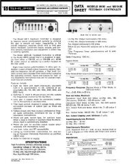
Model <strong>DFR11EQ</strong> <strong>Version</strong> 5Quick Reference <strong>Guide</strong>DIGITAL EQ + FEEDBACK REDUCERBYPASSDFR FILTERS1 2 3SCE NESPRESSTO LOCK DFR FILTERS DATA POWERHOLD TOCLEARDSP • 20 BIT • 48 KHzSIGNAL CLIP<strong>DFR11EQ</strong> <strong>Version</strong> 5Digital Equalizer with Feedback Reducer, Limiter, and DelayEgaliseur graphique numérique à réducteur de Larsen, écrêteur, et délaiDigitaler graphischer Equalizer mit Ruckkopplungsreduzier-Stufe, Limiter, und DelayEcualizador gráfico digital con reductor de realimentación, limitador, y retardoEqualizzatore frafico digitale con attenuatore di retroazione, limitatore, e ritardo©2007 <strong>Shure</strong> Incorporated27C8675 (Rev. 5)*27C8675*Printed in U.S.A.
2TABLE OF CONTENTSENGLISH . . . . . . . . . . . . . . . . . . . . . . . . . . . . . . . . . . . . . . . . . . . . . . . . . . . . . . . . . . . . . . . . . . . . . . . . . . . . . . . . . 3Installing the <strong>DFR11EQ</strong> Software . . . . . . . . . . . . . . . . . . . . . . . . . . . . . . . . . . . . . . . . . . . . . . . . . . . . . . . . . . . . . . . . . . . . . . . . . . . . . . . . . . 3<strong>DFR11EQ</strong> Panels. . . . . . . . . . . . . . . . . . . . . . . . . . . . . . . . . . . . . . . . . . . . . . . . . . . . . . . . . . . . . . . . . . . . . . . . . . . . . . . . . . . . . . . . . . . . . . . 4DIP Switches . . . . . . . . . . . . . . . . . . . . . . . . . . . . . . . . . . . . . . . . . . . . . . . . . . . . . . . . . . . . . . . . . . . . . . . . . . . . . . . . . . . . . . . . . . . . . . . . . . 5Audio Connections . . . . . . . . . . . . . . . . . . . . . . . . . . . . . . . . . . . . . . . . . . . . . . . . . . . . . . . . . . . . . . . . . . . . . . . . . . . . . . . . . . . . . . . . . . . . . . 6Using the <strong>DFR11EQ</strong> as a Stand-alone Feedback Reducer . . . . . . . . . . . . . . . . . . . . . . . . . . . . . . . . . . . . . . . . . . . . . . . . . . . . . . . . . . . . . . . 7Specifications . . . . . . . . . . . . . . . . . . . . . . . . . . . . . . . . . . . . . . . . . . . . . . . . . . . . . . . . . . . . . . . . . . . . . . . . . . . . . . . . . . . . . . . . . . . . . . . . . . 8Audio Connectors. . . . . . . . . . . . . . . . . . . . . . . . . . . . . . . . . . . . . . . . . . . . . . . . . . . . . . . . . . . . . . . . . . . . . . . . . . . . . . . . . . . . . . . . . . . . . . . 9Certifications. . . . . . . . . . . . . . . . . . . . . . . . . . . . . . . . . . . . . . . . . . . . . . . . . . . . . . . . . . . . . . . . . . . . . . . . . . . . . . . . . . . . . . . . . . . . . . . . . . 10Audio Cables . . . . . . . . . . . . . . . . . . . . . . . . . . . . . . . . . . . . . . . . . . . . . . . . . . . . . . . . . . . . . . . . . . . . . . . . . . . . . . . . . . . . . . . . . . . . . . . . . 11Digital Connectors and Cables. . . . . . . . . . . . . . . . . . . . . . . . . . . . . . . . . . . . . . . . . . . . . . . . . . . . . . . . . . . . . . . . . . . . . . . . . . . . . . . . . . . . 12FRANÇAIS . . . . . . . . . . . . . . . . . . . . . . . . . . . . . . . . . . . . . . . . . . . . . . . . . . . . . . . . . . . . . . . . . . . . . . . . . . . . . . . 13Installation du logiciel . . . . . . . . . . . . . . . . . . . . . . . . . . . . . . . . . . . . . . . . . . . . . . . . . . . . . . . . . . . . . . . . . . . . . . . . . . . . . . . . . . . . . . . . . . . 13Matériel <strong>DFR11EQ</strong> . . . . . . . . . . . . . . . . . . . . . . . . . . . . . . . . . . . . . . . . . . . . . . . . . . . . . . . . . . . . . . . . . . . . . . . . . . . . . . . . . . . . . . . . . . . . . 14Interrupteur à positions multiples . . . . . . . . . . . . . . . . . . . . . . . . . . . . . . . . . . . . . . . . . . . . . . . . . . . . . . . . . . . . . . . . . . . . . . . . . . . . . . . . . . 15Branchements audio . . . . . . . . . . . . . . . . . . . . . . . . . . . . . . . . . . . . . . . . . . . . . . . . . . . . . . . . . . . . . . . . . . . . . . . . . . . . . . . . . . . . . . . . . . . 16Utilisation du <strong>DFR11EQ</strong> en tant que réducteur de larsen autonome . . . . . . . . . . . . . . . . . . . . . . . . . . . . . . . . . . . . . . . . . . . . . . . . . . . . . . . 17Caractéristiques . . . . . . . . . . . . . . . . . . . . . . . . . . . . . . . . . . . . . . . . . . . . . . . . . . . . . . . . . . . . . . . . . . . . . . . . . . . . . . . . . . . . . . . . . . . . . . . 18Connecteurs audio . . . . . . . . . . . . . . . . . . . . . . . . . . . . . . . . . . . . . . . . . . . . . . . . . . . . . . . . . . . . . . . . . . . . . . . . . . . . . . . . . . . . . . . . . . . . . 19Homologations . . . . . . . . . . . . . . . . . . . . . . . . . . . . . . . . . . . . . . . . . . . . . . . . . . . . . . . . . . . . . . . . . . . . . . . . . . . . . . . . . . . . . . . . . . . . . . . . 20Câbles audio . . . . . . . . . . . . . . . . . . . . . . . . . . . . . . . . . . . . . . . . . . . . . . . . . . . . . . . . . . . . . . . . . . . . . . . . . . . . . . . . . . . . . . . . . . . . . . . . . 21Connecteurs et câbles numériques . . . . . . . . . . . . . . . . . . . . . . . . . . . . . . . . . . . . . . . . . . . . . . . . . . . . . . . . . . . . . . . . . . . . . . . . . . . . . . . . 22DEUTSCH . . . . . . . . . . . . . . . . . . . . . . . . . . . . . . . . . . . . . . . . . . . . . . . . . . . . . . . . . . . . . . . . . . . . . . . . . . . . . . . 23Installation der Software. . . . . . . . . . . . . . . . . . . . . . . . . . . . . . . . . . . . . . . . . . . . . . . . . . . . . . . . . . . . . . . . . . . . . . . . . . . . . . . . . . . . . . . . . 23<strong>DFR11EQ</strong> Hardware . . . . . . . . . . . . . . . . . . . . . . . . . . . . . . . . . . . . . . . . . . . . . . . . . . . . . . . . . . . . . . . . . . . . . . . . . . . . . . . . . . . . . . . . . . . 24Dip-Schalter . . . . . . . . . . . . . . . . . . . . . . . . . . . . . . . . . . . . . . . . . . . . . . . . . . . . . . . . . . . . . . . . . . . . . . . . . . . . . . . . . . . . . . . . . . . . . . . . . . 25Audio-anschlüsse . . . . . . . . . . . . . . . . . . . . . . . . . . . . . . . . . . . . . . . . . . . . . . . . . . . . . . . . . . . . . . . . . . . . . . . . . . . . . . . . . . . . . . . . . . . . . . 26Verwendung des <strong>DFR11EQ</strong> als Unabhängige Rückkopplungsreduzier-stufe . . . . . . . . . . . . . . . . . . . . . . . . . . . . . . . . . . . . . . . . . . . . . . . . 27Technische Daten . . . . . . . . . . . . . . . . . . . . . . . . . . . . . . . . . . . . . . . . . . . . . . . . . . . . . . . . . . . . . . . . . . . . . . . . . . . . . . . . . . . . . . . . . . . . . 28Audio-Steckverbindungen . . . . . . . . . . . . . . . . . . . . . . . . . . . . . . . . . . . . . . . . . . . . . . . . . . . . . . . . . . . . . . . . . . . . . . . . . . . . . . . . . . . . . . . 29Zertifizierungen. . . . . . . . . . . . . . . . . . . . . . . . . . . . . . . . . . . . . . . . . . . . . . . . . . . . . . . . . . . . . . . . . . . . . . . . . . . . . . . . . . . . . . . . . . . . . . . . 30Audio-Kabel . . . . . . . . . . . . . . . . . . . . . . . . . . . . . . . . . . . . . . . . . . . . . . . . . . . . . . . . . . . . . . . . . . . . . . . . . . . . . . . . . . . . . . . . . . . . . . . . . . 31Digitale Steckverbinder und Kabel . . . . . . . . . . . . . . . . . . . . . . . . . . . . . . . . . . . . . . . . . . . . . . . . . . . . . . . . . . . . . . . . . . . . . . . . . . . . . . . . . 32ESPAÑOL . . . . . . . . . . . . . . . . . . . . . . . . . . . . . . . . . . . . . . . . . . . . . . . . . . . . . . . . . . . . . . . . . . . . . . . . . . . . . . . 33Instalacion del software . . . . . . . . . . . . . . . . . . . . . . . . . . . . . . . . . . . . . . . . . . . . . . . . . . . . . . . . . . . . . . . . . . . . . . . . . . . . . . . . . . . . . . . . . 33Hardware del <strong>DFR11EQ</strong> . . . . . . . . . . . . . . . . . . . . . . . . . . . . . . . . . . . . . . . . . . . . . . . . . . . . . . . . . . . . . . . . . . . . . . . . . . . . . . . . . . . . . . . . 34Interruptores dip . . . . . . . . . . . . . . . . . . . . . . . . . . . . . . . . . . . . . . . . . . . . . . . . . . . . . . . . . . . . . . . . . . . . . . . . . . . . . . . . . . . . . . . . . . . . . . . 35Conexiones de audio . . . . . . . . . . . . . . . . . . . . . . . . . . . . . . . . . . . . . . . . . . . . . . . . . . . . . . . . . . . . . . . . . . . . . . . . . . . . . . . . . . . . . . . . . . . 36Uso del <strong>DFR11EQ</strong> como reductor de realimentacion independiente. . . . . . . . . . . . . . . . . . . . . . . . . . . . . . . . . . . . . . . . . . . . . . . . . . . . . . . 37Especificaciones. . . . . . . . . . . . . . . . . . . . . . . . . . . . . . . . . . . . . . . . . . . . . . . . . . . . . . . . . . . . . . . . . . . . . . . . . . . . . . . . . . . . . . . . . . . . . . . 38Conectores de audio . . . . . . . . . . . . . . . . . . . . . . . . . . . . . . . . . . . . . . . . . . . . . . . . . . . . . . . . . . . . . . . . . . . . . . . . . . . . . . . . . . . . . . . . . . . 39Certificaciones . . . . . . . . . . . . . . . . . . . . . . . . . . . . . . . . . . . . . . . . . . . . . . . . . . . . . . . . . . . . . . . . . . . . . . . . . . . . . . . . . . . . . . . . . . . . . . . . 40Cables de audio . . . . . . . . . . . . . . . . . . . . . . . . . . . . . . . . . . . . . . . . . . . . . . . . . . . . . . . . . . . . . . . . . . . . . . . . . . . . . . . . . . . . . . . . . . . . . . . 41Conectores y cables para señales digitales . . . . . . . . . . . . . . . . . . . . . . . . . . . . . . . . . . . . . . . . . . . . . . . . . . . . . . . . . . . . . . . . . . . . . . . . . . 42ITALIANO. . . . . . . . . . . . . . . . . . . . . . . . . . . . . . . . . . . . . . . . . . . . . . . . . . . . . . . . . . . . . . . . . . . . . . . . . . . . . . . . 43Installazione del software . . . . . . . . . . . . . . . . . . . . . . . . . . . . . . . . . . . . . . . . . . . . . . . . . . . . . . . . . . . . . . . . . . . . . . . . . . . . . . . . . . . . . . . . 43Hardware del <strong>DFR11EQ</strong> . . . . . . . . . . . . . . . . . . . . . . . . . . . . . . . . . . . . . . . . . . . . . . . . . . . . . . . . . . . . . . . . . . . . . . . . . . . . . . . . . . . . . . . . 44Interruttori dip . . . . . . . . . . . . . . . . . . . . . . . . . . . . . . . . . . . . . . . . . . . . . . . . . . . . . . . . . . . . . . . . . . . . . . . . . . . . . . . . . . . . . . . . . . . . . . . . . 45Collegamenti audio. . . . . . . . . . . . . . . . . . . . . . . . . . . . . . . . . . . . . . . . . . . . . . . . . . . . . . . . . . . . . . . . . . . . . . . . . . . . . . . . . . . . . . . . . . . . . 46Uso del <strong>DFR11EQ</strong> come attenuatore di retroazione autonomo. . . . . . . . . . . . . . . . . . . . . . . . . . . . . . . . . . . . . . . . . . . . . . . . . . . . . . . . . . . 47Dati tecnici . . . . . . . . . . . . . . . . . . . . . . . . . . . . . . . . . . . . . . . . . . . . . . . . . . . . . . . . . . . . . . . . . . . . . . . . . . . . . . . . . . . . . . . . . . . . . . . . . . . 48Connettori audio . . . . . . . . . . . . . . . . . . . . . . . . . . . . . . . . . . . . . . . . . . . . . . . . . . . . . . . . . . . . . . . . . . . . . . . . . . . . . . . . . . . . . . . . . . . . . . . 49Omologazioni . . . . . . . . . . . . . . . . . . . . . . . . . . . . . . . . . . . . . . . . . . . . . . . . . . . . . . . . . . . . . . . . . . . . . . . . . . . . . . . . . . . . . . . . . . . . . . . . . 50Cavi audio . . . . . . . . . . . . . . . . . . . . . . . . . . . . . . . . . . . . . . . . . . . . . . . . . . . . . . . . . . . . . . . . . . . . . . . . . . . . . . . . . . . . . . . . . . . . . . . . . . . 51Connettori e cavi digitali . . . . . . . . . . . . . . . . . . . . . . . . . . . . . . . . . . . . . . . . . . . . . . . . . . . . . . . . . . . . . . . . . . . . . . . . . . . . . . . . . . . . . . . . . 52. . . . . . . . . . . . . . . . . . . . . . . . . . . . . . . . . . . . . . . . . . . . . . . . . . . . . . . . . . . . . . . . . . . . . . . . . . . . . . . . . . . 53<strong>DFR11EQ</strong> . . . . . . . . . . . . . . . . . . . . . . . . . . . . . . . . . . . . . . . . . . . . . . . . . . . . . . . . . . . . . . . . . . . . . . . . . . . . . . . . . . . . . . . . . . . . 54 . . . . . . . . . . . . . . . . . . . . . . . . . . . . . . . . . . . . . . . . . . . . . . . . . . . . . . . . . . . . . . . . . . . . . . . . . . . . . . . . . . . . . . . . . . . . 55 . . . . . . . . . . . . . . . . . . . . . . . . . . . . . . . . . . . . . . . . . . . . . . . . . . . . . . . . . . . . . . . . . . . . . . . . . . . . . . . . . . . . . . . . . . . . . . . 56<strong>DFR11EQ</strong> . . . . . . . . . . . . . . . . . . . . . . . . . . . . . . . . . . . . . . . . . . . . . . . . . . . . . . 57 . . . . . . . . . . . . . . . . . . . . . . . . . . . . . . . . . . . . . . . . . . . . . . . . . . . . . . . . . . . . . . . . . . . . . . . . . . . . . . . . . . . . . . . . . . . . . . . . . . . . . . . . 58 . . . . . . . . . . . . . . . . . . . . . . . . . . . . . . . . . . . . . . . . . . . . . . . . . . . . . . . . . . . . . . . . . . . . . . . . . . . . . . . . . . . . . . . . 59 . . . . . . . . . . . . . . . . . . . . . . . . . . . . . . . . . . . . . . . . . . . . . . . . . . . . . . . . . . . . . . . . . . . . . . . . . . . . . . . . . . . . . . . . . . . . . . . . . . . . . . . . 60 . . . . . . . . . . . . . . . . . . . . . . . . . . . . . . . . . . . . . . . . . . . . . . . . . . . . . . . . . . . . . . . . . . . . . . . . . . . . . . . . . . . . . . . . . . 61 . . . . . . . . . . . . . . . . . . . . . . . . . . . . . . . . . . . . . . . . . . . . . . . . . . . . . . . . . . . . . . . . . . . . . . . . . . . . . . . . . 62
ENGLISH<strong>DFR11EQ</strong> VERSION 5 QUICK REFERENCE GUIDEThe <strong>Shure</strong> <strong>DFR11EQ</strong> <strong>Version</strong> 5 offers the user a wide variety of digital sound processing capabilities. The <strong>DFR11EQ</strong> is most commonly controlledthrough its software interface; however, the system can be used effectively as a stand-alone product.This quick reference guide provides all necessary information for the installation of the operating software, as well as for use of the <strong>DFR11EQ</strong>without the computer interface. Additional information on the advanced characteristics of the software is offered in the complete user guide includedon the furnished CD-Rom. The user guide can be used on line or printed. In addition, the system software includes searchable online help.For information on the following topics, please see the full version of the <strong>DFR11EQ</strong> <strong>Version</strong> 5 user guide on the furnished CD-Rom.• Characteristics of the hardware and the software• Using the <strong>Shure</strong> Link system• Full operation of the <strong>DFR11EQ</strong> <strong>Version</strong> 5 software• Feedback reduction software• Graphic and parametric equalizers• Digital delay software• Clipping reduction softwareINSTALLING THE <strong>DFR11EQ</strong> SOFTWAREMINIMUM COMPUTER REQUIREMENTSThe following are the minimum requirements to install and run the <strong>DFR11EQ</strong> <strong>Version</strong> 5 software.• One 486DX 50 MHz IBM*-compatible computer (mathcoprocessor required)• 2 MB hard drive space• 4 MB RAMCONNECTING THE <strong>DFR11EQ</strong> TO A COMPUTER VIA THE RS-232 (COM) PORT• CD-ROM drive• Windows version 3.1x, 95, 98 or NT• 1 available RS-232 serial (COM) port• One RS-232 cable (9-pin to 9-pin)TO COMPUTERRS-232 CONNECTORTO <strong>DFR11EQ</strong> RS-232CONNECTOR (9-PIN MALE)1. Connect a 9-pin plug (male) of the cable to the RS-232 port of the<strong>DFR11EQ</strong>.2. Connect the other end of the cable to the RS-232 port of the computer.SOFTWARE INSTALLATION1. Insert the supplied CD-ROM into the CD-ROM drive of your computer.(After initial installation, the CD-ROM is not necessary to run the software.)2. When the installation menu appears, click on <strong>DFR11EQ</strong> Software.You will be led through the installation process. Note: if you are usingWindows 3.1X, go to File/Run and run d:\SETUP16.EXE.3. <strong>Shure</strong> Setup will suggest a destination on your hard disk for the<strong>DFR11EQ</strong> files and will check the computer hardware to ensure that acoprocessor is present. It will also prompt you for your name andorganizational information.NOTE: Remember to register your software by filling out and mailing the enclosed registration card, or online via the <strong>Shure</strong> World WideWeb site ("http://www.shure.com"). This will ensure that you receive information about software updates with additional features as theybecome available.ACCESSING THE ONLINE USER GUIDE1. Insert the CD-Rom in your computer’s CD-Rom drive. (<strong>User</strong>s of Windows3.1x: double-click on the "Setup 16" icon in the file of the CD-Rom.)2. An installation menu appears. Double-click on View <strong>User</strong> <strong>Guide</strong>s, thenchoose your preferred language.3. The user guide is in PDF format. Acrobat Reader is necessary to viewPDF documents. Acrobat Reader is included on the CD-Rom, andshould be installed if necessary.4. The full guide, or required sections of the guide, may be viewed onlineor printed.3
ENGLISH<strong>DFR11EQ</strong> PANELSFRONT PANEL BYPASS DFR FILTERS Button and LED. Press this button to suspend feedback reducer operation and remove feedback filters fromthe audio path. The bypass does not affect the equalizer, delay or limiter. When the LED illuminates, the feedback reducer is bypassed. SIGNAL LED. Illuminates when input signal is present. Intensity varies with input signal level. CLIP LED. Illuminates when the input signal is within 6 dB of clipping. SCENE Selection Buttons and LEDs. Press one of these three buttons to select a pre-set scene. When a scene is selected, the correspondingLED will light. LOCK/CLEAR Filters Button and LED. Press and release this button to lock the filters you have set. Hold down the button for threeseconds, and the filters will clear. The LED indicates that the filters are locked. DFR FILTER LEDs (10). Indicate when individual feedback filters are active. When a filter changes or is added, the LED flashes, thenstays on. DATA LED. Flashes in unison with the feedback filter LEDs when the detector is deploying a new feedback filter or changing an existingone, and also blinks whenever the unit is communicating with a connected computer. POWER LED. LED illuminates when unit is attached to a power supply.BACK PANEL Power Connector with Integral Fuse. Connects to AC power. The fuse is located in the drawer below the connector. 9-Pin RS-232 Port. Connects the unit to a computer. For use with <strong>DFR11EQ</strong> software and for DSP firmware upgrades. (Compatible withAMX and Crestron systems. <strong>Shure</strong> Link Interface. Allows linking of up to 16 <strong>Shure</strong> Link devices (<strong>DFR11EQ</strong>s, DP11EQs, and UA888s), which may be accessed bycomputer. DIP Switches. Switches 1 through 4 are used to select the device ID. Switches 5 through 10 change other available options. See DIPSwitches. Separate ¼” and XLR audio output jacks. Combined ¼” and XLR audio output jacks.4
ENGLISHDIP SWITCHESThere are ten DIP Switches located on the back of the <strong>DFR11EQ</strong>. The following table describes the function of each switch. See the <strong>DFR11EQ</strong><strong>User</strong>’s <strong>Guide</strong> on the Software CD ROM for instructions on how to set the Device ID.UP 1DN1DEVICE ID2 32 344LOW QHIGH QHOLD UPDATELOCK UNLOCK FRONT PANELUNUSED UNUSED-10 +4 OUTPUT-10 +4 INPUTDIP SWITCH FUNCTION POSITIONUP1-4 <strong>Shure</strong> Link Device ID (see CD-Rom user guide)5 Feedback Filter Bandwidth SelectDetermines the Q of the feedback filter.High Q1/10–octave Feedback Filters remain narrow asthey deepen6 Feedback Filter Memory Mode UpdateStores changed feedback filter settings onpower down7 Front Panel Lockout Unlock Front PanelFront panel buttons operational8 unused - -9* Output Sensitivity +4 dBu Output –10 dBV Output10* Input Sensitivity +4 dBu Input –10 dBV InputDOWNLow Q1/10–octave Feedback Filters widen as theydeepenHoldDiscards changed feedback filter settings onpower down, but holds original settingsLockFront panel buttons inactive (except the powerswitch).*NOTE: See the Set Up instructions in the Using the <strong>DFR11EQ</strong> as a Stand-Alone Feedback Reducer section of this Quick Reference<strong>Guide</strong> for instructions and warnings regarding use of the Input and Output Sensitivity DIP switches.HOLD/UPDATEUPDATE position... When the HOLD/UPDATE DIP switch is in the UPDATE position (default), the <strong>DFR11EQ</strong> saves the feedback filters everytime the unit is powered off. When the <strong>DFR11EQ</strong> is powered on again, the feedback filters will be at exactly the same settings as when the unit waspowered down.HOLD position... When the HOLD/UPDATE DIP switch is changed to the HOLD position, the <strong>DFR11EQ</strong> immediately saves the feedback filtersat the current settings. When the <strong>DFR11EQ</strong> is powered off, any changes made to the feedback filters after the switch was set will be forgotten. Whenpowered on again, the feedback filter settings will be exactly the same as when the HOLD/UPDATE DIP switch was changed to the HOLD position.This feature is useful for storing the best filter settings for a sound system.To store filter settings in the HOLD memory:1. Set the Hold/Update DIP switch to the Update position;2. Ring out the room until all fixed filters are set;3. Set the Hold/Update DIP switch to the Hold position;4. During the performance, the <strong>DFR11EQ</strong> will change dynamic filters and deepen fixed ones;5. After the performance, turn the power off and back on; the DFR filters are restored to the state they were in before the performance.5
ENGLISHAUDIO CONNECTIONSNOTE: All cables must be shielded.Between the Mixer Main Output and the Power Amplifier The <strong>DFR11EQ</strong> is most commonly placed between the main output of a mixer and theinput of a power amplifier. At the main output, the unit will affect all input channels. This setup is ideal for using the <strong>DFR11EQ</strong> as a feedback reducerand as an equalizer.LINE IN<strong>DFR11EQ</strong>LINE INPOWER AMPLIFIERLINE OUTMIXERLINE OUTLOUDSPEAKERAt a Subgroup Insert When using a multiple bus mixer, the <strong>DFR11EQ</strong> can be connected to a single subgroup insert. The unit will affect only thechannels associated with that subgroup: the other channels will remain unaffected.LINE INSUB SENDSUB RETURNÑÑÑLINEOUTMAIN<strong>DFR11EQ</strong>LINE INÑPOWER AMPLIFIERLINE OUTMIXERLOUDSPEAKERInserted in an Input Channel If only a single microphone is creating feedback problems, the <strong>DFR11EQ</strong> can be inserted on that channel alone.This is especially useful for wireless microphones, because the constant movement of a performer may bring the microphone too close to the soundreinforcement loudspeakers.CHANNEL 1 INLINE INCHANNEL 1INSERTÑLINE OUTMAINLINE OUTLINE INPOWER AMPLIFIER<strong>DFR11EQ</strong>LINE OUTMIXERLOUDSPEAKERWIRELESS RECEIVERInserted Between Mixer and Monitor Since monitor loudspeakers and microphones are usually in close proximity, the <strong>DFR11EQ</strong> can be connectedto stabilize a monitor system. Place a <strong>DFR11EQ</strong> on the monitor output which goes to the monitor loudspeaker. For multiple monitor mixes, a<strong>DFR11EQ</strong> should be placed at the output of each monitor send.LINE INLINE INAUX 1OUTAUX 2OUTLINE IN<strong>DFR11EQ</strong>ÑLINE OUTLINE IN<strong>DFR11EQ</strong>ÑLINE OUTÑMONITORPOWER AMPLIFIERMONITORLOUDSPEAKERMIXER6
ENGLISHUSING THE <strong>DFR11EQ</strong> AS A STAND-ALONE FEEDBACK REDUCERSETUP FOR FEEDBACK CONTROLThere are two basic ways in which to set–up the <strong>DFR11EQ</strong> as a stand–alone feedback reducer: The “Ring Out” method and the “Insurance Policy”method. Each is valid for different situations.The “Ring Out” method is a preemptive measure in which the system gain is raised beyond the normal setting to deliberately make the systemfeed back. The <strong>DFR11EQ</strong> will then set its filters, and the system gain is then reduced slightly, and the system is stable and usable. This set–up methodis primarily used for systems which are operated near the feedback point and need an extra margin of stability.For the “Insurance Policy” method, the <strong>DFR11EQ</strong> is simply installed in the sound system, but filters are not set prior to use. The <strong>DFR11EQ</strong> addsextra insurance against feedback: the system is not expected to feedback, but if it does, the <strong>DFR11EQ</strong> is there to catch it. This set–up method is usedfor systems which already have sufficient gain–before–feedback, but need protection from the occasional stray feedback which can occur due to non–stationary microphones or user–adjustable gain controls.SETUP1. Connect the <strong>DFR11EQ</strong> in the desired signal path location. See AudioConnections.2. Set the input and output level DIP switches to the appropriate settingsfor the sensitivities of the connected equipment.WARNING: Other equipment may potentially be damaged after the <strong>DFR11EQ</strong> is powered off if the<strong>DFR11EQ</strong> input is set to +4 and the output is set to -10. It is recommended that you avoid using this setting.3. Set the system gain to minimum, and power up all of the equipment.4. Slowly raise the gain of the system, and set the gain of each microphoneto achieve the desired level.5. The red CLIP LED should illuminate only on the highest signal peaks.If it illuminates more frequently, check to see that the input levelswitch is set properly. If it is, lower the level of the signal going into the<strong>DFR11EQ</strong>.6. At this point it is highly recommended to equalize the sound systemwith the <strong>DFR11EQ</strong>’s built-in equalizer (see Computer Interface) or anexternal equalizer. The <strong>DFR11EQ</strong>’s feedback reducer is more effectiveon a well-equalized sound system.RINGING OUT THE SYSTEM (“RING OUT” METHOD ONLY)1. If necessary, clear any notch filters in the <strong>DFR11EQ</strong> by pressing theCLEAR button. Turn off the BYPASS and LOCK LEDs if they are notalready off.2. Slowly raise the gain of the signal going through the <strong>DFR11EQ</strong>. Whenfeedback occurs, the <strong>DFR11EQ</strong> will insert a filter deep enough to stopthe feedback.NOTE: If you are using an auto mixer, lock on all inputs during ring-out phase.3. Repeat step 2 until all fixed filters are set. (There are 5 fixed filters,unless changed by the user via the computer interface.)4. Lower the gain by 3 to 6 dB to stabilize the sound system.SCENE SELECTION1 2 3SCENESThere are three SCENE SELECTION buttons and LEDs on the front panel of the <strong>DFR11EQ</strong>. These allow easy access of scenes (preset EQ, DFRfilter and delay settings) without a computer. This allows access to scenes created using the <strong>DFR11EQ</strong> <strong>Version</strong> 5 software after disconnecting thecomputer from the <strong>DFR11EQ</strong>. Alternatively, DFR–only scenes may be created without a computer as follows:1. Select scene one, two or three on the front panel.2. Ring out the system (see Ringing Out the System). The filters created during the ringing out phase will now be recalled whenever theselected scene is chosen.NOTE: The three Scene buttons on the front panel are factory preset to provide a flat response until specific scenes are created by theuser.7
ENGLISHSPECIFICATIONSFrequency Response20 to 20k Hz ± 1.0 dB re 1 kHzDynamic Range104 dB minimum, A-weighted, 20 Hz to 20 kHzSampling Rate48 kHzDigital–to–Analog, Analog–to–Digital Conversion20 bit resolutionVoltage Gain–1 dB ± 1dB (power off)0 dB ± 2 dB (equal input and output sensitivities)12 dB ± 2 dB (input –10 dBV, output +4 dBu)–12 dB ± 2 dB (input +4 dBu, output –10 dBv)ImpedanceInput: 47 kΩ ± 20% actualOutput: 120 Ω ± 20% actualInput Clipping Level+18 dBu minimum (at +4 dBu setting)+6 dBu minimum (at –10 dBV setting)Output Clipping Level+18 dBu minimum (at +4 dBu setting)+6 dBu minimum (at –10 dBV setting)Total Harmonic Distortion< 0.05% at 1 kHz, +4 dBu, 20 to 20 kHzLED Signal IndicatorsClip: 6 dB down from input clippingPropagation Delay from Input to Output< 1.0 ms, all filters set to Flat (0 ms delay setting)PolarityInput to output: non-invertingXLR: pin 2 positive with respect to pin 31 / 4 in. TRS: tip positive with respect to ringOperating Voltage<strong>DFR11EQ</strong>: 120 Vac, 50/60 Hz, 75 mA max<strong>DFR11EQ</strong>J: 100 Vac, 50/60 Hz, 75 mA max<strong>DFR11EQ</strong>E: 230-240 Vac, 50/60 Hz, 38 mA maxTemperature RangeOperating: –7° to 49° C (20° to 140° F)Dimensions219 mm x 137 mm x 44.5 mm (8 5 / 8 in x 5 3 / 8 in x 1 3 / 4 in)Weight930 g (2.05 lbs)Fuse<strong>DFR11EQ</strong>:120 Vac. Fuse: 100 mA, 250V time delay<strong>DFR11EQ</strong>J: 100 Vac.Fuse: 100 mA, 250V time delay<strong>DFR11EQ</strong>E: 230-240 Vac. Fuse: 50 mA, 250 V time delayIn order to change a blown fuse, remove the power cord and pry openthe drawer with a flathead screwdriver.FEEDBACK FILTERSTen (10) 1 / 10 octave adaptive notch filters from 60 Hz to 20 kHzDeployed to 1 Hz resolution of feedback frequencyDeployed in depths of 3 dB, 6 dB, 9 dB, 12 dB, and 18 dB (12.5Low Q in graphic EQ mode) attenuationFilter shape variable between HI Q and LOW Q (see High Q vs.Low Q Filters).GRAPHIC EQUALIZERFrequency Bands30 bands on ISO, 1 / 3 octave centersFilter Type1 / 3 octave, constant QMaximum Boost6 dB per bandMaximum Cut12dB per band, high- and low-pass filters, 12dB/octave nominalPARAMETRIC EQUALIZERFrequency Bands10 bands, variable frequency, variable QBoost/Cut Range+6 dB to –18 dB per bandQ Range1 / 40 octave to 2 octaveShelf/Rolloff FiltersShelf, +6 to –18 dB per filterRolloff, 6dB, 12dB, 18dB, or 24dB per octave nominalDELAYUp to 1300 msFUSELIMITERThreshold: –60 dBFs to –0.5 dBFs, 0.5 dB resolutionAttack: 1 ms to 200 msDecay: 50 ms to 1000 msRatio: ∞ to 18
ENGLISHAUDIO CONNECTORS<strong>DFR11EQ</strong> AUDIO INPUT<strong>DFR11EQ</strong> AUDIO OUTPUTConnector:(XLR and 1/4 inchcombined)XLR (female)1/4 inchphone plug(female)Configuration: active balanced active balancedActual 47 kΩ 47 kΩImpedance:NominalInput Level:MaximumInput Level:PinAssignments:Voltage /Current/Phantom PowerProtection?+4 dBu(+4 input level)–10 dBV(–10 input level)+18 dBu(+4 input level)+6 dBV(–10 input level)Pin 1 = groundPin 2 = hotPin 3 = coldyes+4 dBu(+4 input level)–10 dBV(–10 input level)+18 dBu(+4 input level)+6 dBV(–10 input level)Tip = hotring = coldsleeve = groundyesConnector:(XLR and 1/4 inchseparate)Configuration:ActualImpedance:NominalOutput Level:MaximumOutput Level:PinAssignments:Voltage /Current/Phantom PowerProtection?XLR (male)active balancedcross coupled1/4 inchphone plug(female)120 Ω 120 Ω+4 dBu(+4 output level)–10 dBV(–10 output level)+18 dBu(+4 output level)+6 dBV(–10 output level)Pin 1 = groundPin 2 = hotPin 3 = coldyesactive balancedcross coupled+4 dBu(+4 output level)–10 dBV(–10 output level)+18 dBu(+4 output level)+6 dBV(–10 output level)Tip = hotring = coldsleeve = groundyesFURNISHED ACCESSORIESPower Cable (<strong>DFR11EQ</strong>/<strong>DFR11EQ</strong>J)*............. 95A8389Power Cable (<strong>DFR11EQ</strong>E)* ............................. 95A8247Power Cable Clamp......................................... *95A87125 pin DIN <strong>Shure</strong> Link Cable .............................. 95A8676Single Mount Rack Bracket .............................. 53A8484Dual Mount Rack Bracket................................. 53B8484Straddle Bars .................................................... 53A8443<strong>DFR11EQ</strong> <strong>Version</strong> 5Software/<strong>User</strong>’s <strong>Guide</strong> CD-ROM.................... 95A8830A*NOTE: The power cord and power cable clamp is supplied assembled. If a replacement power cord is needed, a power cord clamp is alsorequired. If not assembled, the power cord clamp should be clamped as close to the female end of the power cord as possible.RACK MOUNTINGSINGLE UNITÑÑÑÑÑÑÑÑÑÑÑÑÑÑÑÑÑÑÑÑÑÑÑÑÑÑÑÑÑÑÑÑDUAL–MOUNTED UNITSÑÑÑÑÑ ÑÑÑÑÑÑÑÑÑÑÑÑÑÑÑÑÑÑÑ ÑÑÑÑÑÑÑÑÑÑÑÑÑÑÑÑÑÑÑÑ ÑÑÑÑÑÑÑÑ9
ENGLISHCERTIFICATIONS<strong>DFR11EQ</strong> (VERSION 5)UL Listed and cUL Listed to UL 6500 and CSA E65. Approved under the Verification provision of FCC part 15 as a Class B Digital Device.<strong>DFR11EQ</strong>E (VERSION 5)Eligible to bear CE marking. Conforms to European Union Low Voltage Directive 2006/95/EC; VDE GS-Certified to EN 60065.Conforms to European EMC Directive 89/336/EEC. Meets applicable tests and performance criteria in European Standard EN55103 (1996) Parts1 and 2, for residential (E1) and light industrial (E2) environments.NOTE:*EMC conformance testing is based on the use of supplied and recommended cable types. The use of other cable types may degradeEMC performance.*Under extremely abnormal conditions of electrical fast transients on the power line, communication may be interrupted between the<strong>DFR11EQ</strong> and the controlling PC. The unit will not be damaged; normal operation will resume after the CONNECT button or command isused to restore the connection*This Class B digital apparatus complies with Canadian ICES-003INFORMATION TO USERChanges or modifications not expressly approved by <strong>Shure</strong> Incorporated could void your authority to operate this equipment.This equipment has been tested and found to comply with the limits for a Class B digital device, pursuant to Part 15 of the FCC Rules. These limitsare designed to provide reasonable protection against harmful interference in a residential installation. This equipment generates, uses and can radiateradio frequency energy and, if not installed and used in accordance with the instructions, may cause harmful interference to radio communications.However, there is no guarantee that interference will not occur in a particular installation. If this equipment does cause harmful interference to radioor television reception, which can be determined by turning the equipment off and on, the user is encouraged to try to correct the interference by oneor more of the following measures:• Reorient or relocate the receiving antenna.• Increase the separation between the equipment and receiver.• Connect the equipment into an outlet on a circuit different from that to which the receiver is connected.• Consult the dealer or an experienced radio/TV technician for help! IMPORTANT SAFETY INSTRUCTIONS !1. READ these instructions.2. KEEP these instructions.3. HEED all warnings.4. FOLLOW all instructions.5. DO NOT use this apparatus near water.6. CLEAN ONLY with dry cloth.7. DO NOT block any ventilation openings. Install in accordance with the manufacturer'sinstructions.8. DO NOT install near any heat sources such as radiators, heat registers, stoves,or other apparatus (including amplifiers) that produce heat.9. DO NOT defeat the safety purpose of the polarized or grounding-type plug. Apolarized plug has two blades with one wider than the other. A grounding typeplug has two blades and a third grounding prong. The wider blade or the thirdprong are provided for your safety. If the provided plug does not fit into your outlet,consult an electrician for replacement of the obsolete outlet.10. PROTECT the power cord from being walked on or pinched, particularly at plugs,convenience receptacles, and the point where they exit from the apparatus.11. ONLY USE attachments/accessories specified by the manufacturer.12.USE only with a cart, stand, tripod, bracket, or tablespecified by the manufacturer, or sold with theapparatus. When a cart is used, use caution whenmoving the cart/apparatus combination to avoidinjury from tip-over.13. UNPLUG this apparatus during lightning storms or when unused for long periods oftime.14. REFER all servicing to qualified service personnel. Servicing is required when theapparatus has been damaged in any way, such as power-supply cord or plug is damaged,liquid has been spilled or objects have fallen into the apparatus, the apparatushas been exposed to rain or moisture, does not operate normally, or has beendropped.15. DO NOT expose the apparatus to dripping and splashing. DO NOT put objects filledwith liquids, such as vases, on the apparatus.16. The MAINS plug or an appliance coupler shall remain readily operable.17. The airborne noise of the apparatus does not exceed 70dB (A).18. Apparatus with CLASS I construction shall be connected to a MAINS socket outletwith a protective earthing connection.19. To reduce the risk of fire or electric shock, do not expose this apparatus to rain ormoisture.20. Do not attempt to modify this product. Doing so could result in personal injuryand/or product failure.This symbol indicates that dangerous voltage constituting arisk of electric shock is present within this unit.This symbol indicates that there are important operating andmaintenance instructions in the literature accompanying this unit.WARNING: Voltages in this equipment are hazardous to life. No user-serviceable parts inside. Refer all servicing to qualified service personnel. Thesafety certifications do not apply when the operating voltage is changed from the factory setting.10
ENGLISHAUDIO CABLESThe variety of connectors on audio equipment sometimes leads to confusion in cabling. The diagrams below provide cabling recommendations formost common cabling situations. The following is not a complete list, only a sample of some of the more commonly used cables and applications.Some of the equipment in a given sound system may have different pinouts than the given examples. Consult the documentation for that equipment.NOTE: All audio cables must be shielded. Except for the <strong>Shure</strong> Link cable, none of the cables shown is supplied with the <strong>DFR11EQ</strong><strong>Version</strong> 5.• Mixer Line Out to <strong>DFR11EQ</strong> Input• <strong>DFR11EQ</strong> Output to Amplifier Input• <strong>DFR11EQ</strong> Output to Mixer Sub Return• Mixer Send to <strong>DFR11EQ</strong> Input• Mixer Sub Send to <strong>DFR11EQ</strong> InputXLR (MALE) TO XLR (FEMALE)PIN 2 +PIN 1¼ IN. TO ¼ IN. BALANCEDSLEEVE RING -PIN 3 -PIN 1PIN 2 +SLEEVETIP +RING -PIN 3 -TIP +¼ IN. TO ¼ IN. UNBALANCEDSLEEVE¼ IN. BALANCED TO ¼ IN. UNBALANCEDSLEEVE RING -SLEEVETIP +SLEEVETIP +TIP +TIP +XLR (MALE) TO ¼ IN. BALANCEDPIN 2 +PIN 1XLR (FEMALE) TO ¼ IN. BALANCEDPIN 1PIN 2 +PIN 3 -SLEEVE RING -PIN 3 -SLEEVE RING -TIP +XLR (FEMALE) TO ¼ IN. UNBALANCEDPIN 1PIN 2 +RCA TO ¼ IN. UNBALANCED• <strong>DFR11EQ</strong> output to amplifier inputSLEEVETIP +PIN 3 -SLEEVETIP +SLEEVETIP +TIP +Y-ADAPTER CABLE, ¼ IN. BALANCED TO ¼ IN. UNBALANCED• Mixer send/return (insert) to <strong>DFR11EQ</strong> input and outputRING -SLEEVETIP +11
ENGLISHDIGITAL CONNECTORS AND CABLESBRETELLE ¼ PO SYMÉTRIQUE À ¼ PO ASYMÉTRIQUENOTE: All digital connectors and cables must be shielded.COMPUTER INTERFACE: 9-PIN TO 9-PIN RS-232 CABLE543211 32 459-PIN FEMALETO COMPUTERFUNCTION PIN #9-PIN MALETO <strong>DFR11EQ</strong>8 69 71 3 52 47 96 867589COMPUTER 9-PIN RS-232MALE CONNECTOR3 14 29 78 6<strong>DFR11EQ</strong> RS-232FEMALE CONNECTOR- 1RX 2TX 3DTR 4GND 5DSR 6RTS 7CTS 8- 9SHURE LINK CABLE: 5-PIN DIN CABLE (MIDI-COMPATIBLE CABLE)142355 43 2 1SHURE LINK INFUNCTION PIN #- 1DATA 4SHIELD 2DATA 5- 3142355 43 2 1SHURE LINK OUT12
www.shure.comUnited States:<strong>Shure</strong> Incorporated5800 West Touhy AvenueNiles, IL 60714-4608 USAPhone: 847-600-2000Fax: 847-600-1212Email: info@shure.com©2007 <strong>Shure</strong> IncorporatedEurope, Middle East, Africa:<strong>Shure</strong> Europe GmbHWannenäckestr. 28,74078 Heilbronn, GermanyPhone: 49-7131-72140Fax: 49-7131-721414Email: info@shure.deAsia, Pacific:<strong>Shure</strong> Asia LimitedUnit 301, 3rd FloorCiticorp Centre18, Whitfield RoadCauseway Bay, Hong KongPhone: 852-2893-4290Fax: 852-2893-4055Email: info@shure.com.hkCanada, Latin America,Caribbean:<strong>Shure</strong> Incorporated5800 West Touhy AvenueNiles, IL 60714-4608 USAPhone: 847-600-2000Fax: 847-600-6446Email: international@shure.com