
You also want an ePaper? Increase the reach of your titles
YUMPU automatically turns print PDFs into web optimized ePapers that Google loves.
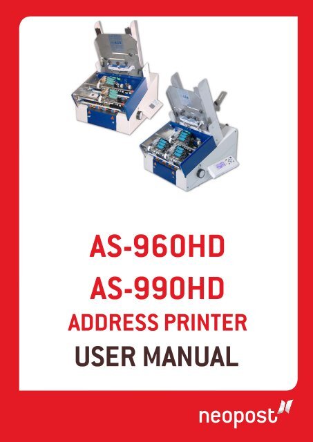
as-960HDas-990HDaDDress PrInTer<strong>User</strong> ManUal
Products presented in this guide are conform torequirements of directives nbr 2006/42/EGand 2004/108/EG.<strong>Neopost</strong> has implemented a program for therecycling of worn machines and machines atthe end of their lifetime. Contribute in a responsibleway to the environmental protectionby consulting your retailer internet site, orby contacting him. He will inform you of thecollection and treatment processes of thesemachines.
Pos: 3 /[Allgemeines]/0.0a_Note_Trademarks+Manufacturer Address NEOPOST @ 1\mod_1256739001883_912.doc @ 7153 @Pos: 4 /Bedienungsanleitungen/Geräte spezifisch/Drucker/AS-960HD/AS-990HD/0.0_Revision level_AS-960HD/990HD 3.1 @ 3\mod_1301662992031_912.doc @ 31015 @Pos: 5 /[Allgemeines]/0.2_Inhaltsverzeichnis @ 0\mod_1242731641668_912.doc @ 1625 @aCopyright© Copyright 2011All rights reserved. No part of this manual may be reproduced or transmitted in any form orby any means, copied onto electronic media or translated into any language without themanufacturer's express written permission.The manufacturer is not liable for any damage resulting either from incorrect use or fromrepairs and modifications carried out by a third unauthorized party. This manual wasproduced with great care. However, liability for any errors which it may contain is excluded.The manufacturer reserves the right to make any technical or design changes to theequipment during the development process. All specified values are purely nominal.Consequently, any legal claims made on the basis of this manual cannot be enforced.The manufacturer is not liable for any damage or disturbance resulting from the use ofoptions or accessories which are not original products or do not have the express approvalof the manufacturer.Brands:HP is a registered brand name of the Hewlett-Packard Company.Microsoft and Windows are registered brand names of the Microsoft Corporation.FlexMail is a registered brand name of Flex Systems B.V.Bulk Mailer is a registered brand name of Satori Software Inc.Manufacturer Address<strong>Neopost</strong> IndustrieZI Tivoli72800 Le LudeFrancewww.neopost.comRevision levelVersion Change description Released3.0 New document for graphic display and November 2010firmware version 4.73.1• Added descriptions for new USB 2.0and TCP/IP interfaceApril 2011• Changed description to firmwareversion 4.8• Added Device Class A note<strong>User</strong> Manual Version 3.1 3
Table of Contents1 Introduction .............................................................................101.1 Pictograms ............................................................................101.2 Notes for use of this manual.....................................................101.3 Terms and abbreviations .........................................................111.4 System requirements ..............................................................112 Safety notes .............................................................................122.1 General safety notes ...............................................................122.2 Ink safety notice.....................................................................142.3 Location of the printer .............................................................152.4 Disposal ................................................................................153 Scope of delivery and assembly................................................163.1 Scope of delivery ....................................................................163.2 Delivery ................................................................................173.3 Device overview .....................................................................193.4 Assembly ..............................................................................213.4.1 Connecting the power cable ................................................ 223.4.2 How to mount the stacking plate and the guides .................... 224 Description of device ................................................................254.1 Application range....................................................................254.2 Description of functions ...........................................................254.3 The Operator Panel .................................................................274.3.1 Key panel......................................................................... 284.3.2 Main Display ..................................................................... 305 Initial start-up of the device.....................................................335.1 How to power-on the device.....................................................335.2 How to install the ink cartridges................................................335.3 How to set up the paper transport.............................................355.3.1 How to adjust the paper separation...................................... 355.3.2 How to adjust the side guides and the feed ramp ................... 375.3.3 How to adjust the printer to the material thickness ................ 385.3.4 How to position the print area ............................................. 395.4 How to measure the print media size.........................................425.5 How to set the print direction (orientation).................................434 <strong>User</strong> Manual Version 3.1
5.6 How to perform a test print...................................................... 446 Printer menu (firmware V4.8).................................................. 457 How to connect the printer to the PC ....................................... 917.1 How to install the printer driver ................................................ 927.2 Windows XP and Windows Vista................................................ 927.2.1 Windows 7........................................................................ 937.3 How to use the USB interface................................................... 957.4 How to use the Ethernet interface............................................. 957.4.1 Adding a TCP/IP port to a printer driver ................................ 977.4.2 Connecting the printer to a local area network ..................... 1007.4.3 Using a fixed IP address ................................................... 1007.4.4 Direct Ethernet connection between the printer and the PC .... 1038 Service ................................................................................... 1058.1 Maintenance and support....................................................... 1058.1.1 How to clean an ink cartridge ............................................ 1058.1.2 How to clean the pen board contacts .................................. 1068.1.3 How to reset the printer.................................................... 1088.2 Troubleshooting ................................................................... 1098.2.1 The device cannot be turned on ......................................... 1098.2.2 No or only very weak printout with new ink cartridges........... 1098.2.3 Printed elements positioned incorrectly ............................... 1108.2.4 The printout looks partly smeared ...................................... 1118.2.5 The printed ink doesn’t dry on the substrate ........................ 1118.2.6 White streaks in printed text or graphic .............................. 1128.2.7 White streak in printed text or graphics (in between cartridges) ..1138.3 Error Messages .................................................................... 1148.3.1 How to read an error message entry................................... 1148.4 Warning Messages................................................................ 1298.4.1 How to read a warning message entry ................................ 1298.4.2 Additional Error Messages ................................................. 1358.5 Technical Support................................................................. 1399 Consumables and Accessories ................................................ 1409.1 Consumables ....................................................................... 1409.1.1 Standard inks for <strong>Neopost</strong> address printers.......................... 1409.1.2 Cleaning Towels............................................................... 1419.2 Accessories.......................................................................... 1429.2.1 Roller cleaning tool for AS-960HD and AS-990HD ................. 142<strong>User</strong> Manual Version 3.1 5
Pos: 6 /[Allgemeines]/0.3_Abbildungsverzeichnis [Figure] @ 0\mod_1250599665953_912.doc @ 2745 @9.2.2 Roller support kit..............................................................1439.2.3 Universal paper basket......................................................1449.2.4 POM separator rollers........................................................1459.3 Accessory devices................................................................. 1469.3.1 <strong>Neopost</strong> CS-800 conveyor .................................................14610 Technical Specifications ......................................................... 14711 Appendix ................................................................................ 14911.1 How to completely remove printer drivers from Windows Vistaand Windows 7 .......................................................................... 14911.2 How to completely remove printer drivers from Windows XP andWindows 2000 ........................................................................... 15011.2.1 How to use a pre-installed printer driver ..............................15111.3 USB connection............................................................... 15111.3.1 Ethernet connection..........................................................15211.3.2 How to identify the USB port used by the printer ..................15311.3.3 How to test the Ethernet connectivity ..................................15411.3.4 Sample settings for Ethernet connection ..............................15611.4 How to exchange or modify the separator rollers ................. 15811.5 How to create a print file .................................................. 16111.6 How to update the flashware............................................. 16311.6.1 How to update the flashware..............................................16311.7 Ink package ID number.................................................... 16611.7.1 ID: 6030206....................................................................16711.8 Declaration of conformity ................................................. 16812 Glossary ................................................................................. 17013 Index...................................................................................... 1766 <strong>User</strong> Manual Version 3.1
Table of FiguresFigure 1: Lifting the printer out of the box, Transportation locks ................................... 17Figure 2: Removing the transportation locks, side views .............................................. 18Figure 3: overview ................................................................................................. 19Figure 4: Separator rollers, passive rollers ................................................................. 20Figure 5: overview assembled .................................................................................. 21Figure 6: Assembly of the stacking plate.................................................................... 22Figure 7: Mounted paper feed ramp .......................................................................... 24Figure 8: The AS-960HD printer ............................................................................... 25Figure 9: The AS-990HD/AS-990HD LOG printer......................................................... 25Figure 10: The operator panel.................................................................................. 27Figure 11: Main display ........................................................................................... 30Figure 12: Inserting the ink cartridge into the pen stall................................................ 34Figure 13: Lock the restraining lever ......................................................................... 34Figure 14: Separator system.................................................................................... 36Figure 15: Separator system adjustment I ................................................................. 36Figure 16: Separator system adjustment II................................................................ 36Figure 17: Separator system adjustment III............................................................... 36Figure 18: Adjusting the paper feed ramp and the slide, side view................................. 37Figure 19: Filing the stack with a fanned out pile, side view.......................................... 37Figure 20: Adjusting the printer to the material thickness ............................................ 38Figure 21: Positioning the vertical print area, AS-960HD .............................................. 39Figure 22: Unprintable area AS-960HD, top view ........................................................ 39Figure 23: Unprintable area AS-990HD, top view ........................................................ 40Figure 24: Printable area AS-960HD unit 1/2............................................................. 41Figure 25: Printable area AS-990HD unit 2................................................................ 41Figure 26: Printable area AS-990HD unit 1/3............................................................. 41Figure 27: Positioning the sand rollers outside the print image...................................... 42Figure 28: Testprint................................................................................................ 44Figure 29: Keep Alive function.................................................................................. 55Figure 30: PRINT CORR.PATT................................................................................... 56Figure 31: Horizontal alignment U1-U2...................................................................... 57Figure 32: ADJUST TOF test print ............................................................................. 59Figure 33: Difference Nor/Rev.................................................................................. 70Figure 34:LEFT MARGIN, transport direction............................................................... 70Figure 35: Encoder Pattern ...................................................................................... 82<strong>User</strong> Manual Version 3.1 7
Figure 36: Simult. PrintUnits service print.................................................................. 83Figure 37: Pattern A ............................................................................................... 83Figure 38: Pattern A with defects ............................................................................. 84Figure 39: Cartridge contacts................................................................................... 84Figure 40: Pattern B ............................................................................................... 85Figure 41: Pattern C ............................................................................................... 85Figure 42: Sample character set print ....................................................................... 86Figure 43: Sample setting dump print ....................................................................... 87Figure 44: Sample Input Buffer Dump print ............................................................... 88Figure 45: New Hardware Wizard ............................................................................. 92Figure 46: Recommended install procedure................................................................ 92Figure 47: Properties of unspecified device ................................................................ 94Figure 48: Update the printer driver.......................................................................... 94Figure 49: Update Driver Software Wizard ................................................................. 95Figure 50: Select the driver source ........................................................................... 95Figure 51: Ferrite with plastic case ........................................................................... 96Figure 52: Adding TCP/IP Port.................................................................................. 97Figure 53: TCP/IP Printer Port Wizard........................................................................ 98Figure 54: IP address of the printer .......................................................................... 98Figure 55: Custom settings...................................................................................... 98Figure 56: Custom settings of printer port ................................................................. 98Figure 57: Address printer port settings .................................................................... 99Figure 58: DHCP Table on server............................................................................ 102Figure 59: Test of fix IP (ping test on server) ........................................................... 102Figure 60: Local Area Connection Properties............................................................. 104Figure 61: TCP/IPv4 settings ................................................................................. 104Figure 62: Cleaning the nozzle plate ....................................................................... 106Figure 63: Nozzle plate and contacts....................................................................... 106Figure 64: Pen board contacts................................................................................ 107Figure 65: Position of element on material ............................................................... 110Figure 66: Smeared test print ................................................................................ 111Figure 67: White streaks in text ............................................................................. 112Figure 68: White streaks in between two cartridges .................................................. 113Figure 69: Usage of the cleaning tool ...................................................................... 143Figure 70: Paper catch tray assembly...................................................................... 145Figure 71: New hardware detected ......................................................................... 1528 <strong>User</strong> Manual Version 3.1
Pos: 7 /Bedienungsanleitungen/Geräte neutral/1.0_Ü1_Einführung_allgemein @ 0\mod_1242731723794_912.doc @ 1634 @ 1Figure 72: Found New Hardware Wizard .................................................................. 152Figure 73: Device Manager .................................................................................... 154Figure 74: Device Properties - Details ..................................................................... 154Figure 75: Command Prompt reply OK .................................................................... 155Figure 76: Command Prompt reply NOT OK ............................................................. 155Figure 77: Assembled stacking plate ....................................................................... 159Figure 78: Dismounting the stacking plate ............................................................... 159Figure 79: Exchange or modify the separator rollers.................................................. 160Figure 80: Print dialog window ............................................................................... 161Figure 81: Print to file dialog.................................................................................. 161Figure 82: Printer port properties ........................................................................... 162<strong>User</strong> Manual Version 3.1 9
Pos: 8 /Bedienungsanleitungen/Geräte neutral/1.1_Ü2_Piktogramme_allgemein @ 0\mod_1242731723997_912.doc @ 1638 @ 2Pos: 9 /Bedienungsanleitungen/Geräte neutral/1.2_Ü2_Hinweise zum Gebrauch dieses Handbuches @ 0\mod_1249459443010_912.doc @ 2613 @ 2Pos: 10 /Bedienungsanleitungen/Geräte spezifisch/Drucker/1.3_Ü2_Terms and abbreviations @ 1\mod_1260869177556_912.doc @ 8380 @ 21 IntroductionIn order to ensure both long service life of the AS-960HD/AS-990HDand its components, as well as safe conditions of use, we recommendthat you read carefully and comply with the operating instructionsand safety notes. Always be aware of all warnings and notes that areaffixed to or printed on the machine itself.All persons who are to handle this machine must also be familiar with the operating manual.Store this manual in a safe place where it is easily accessible for future reference at anytime.1.1 PictogramsGeneral warningsWarning of danger from electricity or electrical shockWarning of possible fireInformation / Note indicating important information regardingthe handling of the machine.1.2 Notes for use of this manualThis manual is structured chronologically, and therefore ordered sequentially from thereceipt of the machine packed up to its ready-for-use state.If you are unfamiliar with the machine, it is best to read through the manual from beginningto end, where you can follow easy step by step instructions to allow you to fully andcorrectly operate the machine.If you are already familiar with the AS-960HD/AS-990HD, it will make things easy if you touse this manual as a reference work.10 <strong>User</strong> Manual Version 3.1
Pos: 11 /Bedienungsanleitungen/Geräte spezifisch/Drucker/1.4_Ü2_System requirements_ONLY_619 @ 2\mod_1272530190780_912.doc @ 17229 @ 2Pos: 12 /Bedienungsanleitungen/Geräte neutral/2.0_Ü1_Sicherheitshinweise @ 0\mod_1242735234414_912.doc @ 1664 @ 11.3 Terms and abbreviationsThis <strong>User</strong> Manual uses the following terms and abbreviations related to the <strong>Neopost</strong> AS-960HD/AS-990HD:• cartridge = Crt = C, C1, C2, C3• print unit = Unit = U, U1, U2A print unit always consists of three ink cartridges.• print media width = expansion of the print media in transport direction.• print media height = expansion of the print media across the transport direction.1.4 System requirementsThe <strong>Neopost</strong> AS-960HD/AS-990HD is designed to be used in connection with a PC. Toconnect the AS-960HD/AS-990HD to the PC one free USB port or one free Ethernet (TCP/IP)port is required. The PC should be an up-to-date model and must have enough processingpower and free disk space to run the <strong>Neopost</strong> Addressing Solutions Software.We recommend using one of the following operating systems:• Microsoft Windows 2000 (SP4)• Microsoft Windows XP (SP3)• Microsoft Windows Vista (SP2) (32- or 64-bit)• Microsoft Windows 7 (32- or 64-bit)<strong>User</strong> Manual Version 3.1 11
Pos: 13 /Bedienungsanleitungen/Geräte neutral/2.1a_Ü2_Allgemeine Sicherheitshinweise_Handbuch @ 0\mod_1249563586836_912.doc @ 2673 @ 2Pos: 14 /Bedienungsanleitungen/Geräte neutral/2.1c_Allgemeine Sicherheitshinweise_Aufstellen des Gerätes @ 0\mod_1242736827044_912.doc @ 1710 @Pos: 15 /Bedienungsanleitungen/Geräte neutral/2.1e_Allgemeine Sicherheitshinweise_Elektrische Gefahren_ZWEIPOLIG @ 0\mod_1242736827372_912.doc @ 1718 @Pos: 16 /Bedienungsanleitungen/Geräte neutral/2.1f_Allgemeine Sicherheitshinweise_Betriebssicherheit/Reinigung/Service @ 0\mod_1242736827200_912.doc @ 1714 @2 Safety notesPrior to initial operation, please carefully read the following instructions for the sake of bothyour own safety and the printer operating safety. Always observe any warnings andinstructions directly attached to the device. Keep this manual available in order to be able tocheck back at any time.Disregarding this manual may cause• electric shock,• injury by being drawn into the transport belt or transport rollers,• damage to the equipment.2.1 General safety notesCaution!Please read these notes with care.Keep this manual for future reference.All notes and warnings found on the machine are to be followed.Setting up themachineA safe, level position is necessary, when installing the machine.Injuries may be caused by tipping, rolling away or falling.The machine is to be protected from moisture.The machine is not suitable for outdoor use.ElectricalHazardsThe power cable must only be connected to a socket with protectivegrounding contact! The protective effect must not be compromised bythe use of an extension cable without a protective groundingconductor. All interruptions of the protective grounding conductor,within or outside of the machine, are prohibited.When fuse failure occurs, electrical machine parts can still carryvoltage.When making the connection to the mains power, be aware of theconnection values on the rating plate.Run the power cable in such a way, that no one can trip over it. Donot place any objects on the power cable.When the machine is not in use over a long period of time, it shouldbe disconnected from the power supply in order to avoid any damagein the event of a voltage surge.Protect the device from moisture. When moisture enters the machine,there is a danger of electrical shock.Never open the machine. For reasons of electrical safety, the machineshould only be opened by authorized service personnel.12 <strong>User</strong> Manual Version 3.1
Pos: 17 /Bedienungsanleitungen/Geräte neutral/2.1g_Allgemeine Sicherheitshinweise_Ersatzteile/Reparaturen/Umbauverbot @ 0\mod_1249462580902_912.doc @ 2637 @Pos: 18 /Bedienungsanleitungen/Geräte neutral/2.1h_Allgemeine Sicherheitshinweise_Hinweis Service @ 0\mod_1242737415895_912.doc @ 1746 @Pos: 19 /Bedienungsanleitungen/Geräte spezifisch/Drucker/2.2_Ü2_Ink safety notice @ 1\mod_1260870536312_912.doc @ 8392 @ 2OperatingsafetyCleaning themachineMachineinspectionsonly byauthorizedServicePartners!Never put your hands inside the machine when it is running!There is a danger that injuries can occur through being pulled in andbeing crushed on the transport belt or the rotating rollers. In addition,keep long hair and parts of loose clothing away from the machinewhile it is in operation.In order to prevent damage to the machine, only factory authorizedaccessory parts should be used.Prior to cleaning the machine, it should be disconnected from thepower outlet. When cleaning the machine, do not use liquid or spraycleaners, but only a cloth dampened with water.Additional information concerning the cleaning of the device can befound in chapter „Maintenance and support“.In the following cases, you should unplug the machine from thepower outlet and contact an authorized service technician:• When the power cable or its plug is worn or damaged.• When water or other liquid has entered the device.• When the device has been dropped/knocked over or the housing isdamaged.• When there is a significant change in the performance of themachine.Spare partsRepairsModification isnot permittedWhen repair work is carried out, only original spare parts or spareparts approved by the manufacturer may be used.Do not disassemble the machine any further than it is described inthis manual. The opening of the machine by unauthorized personnelis not permitted. Repairs may only be carried out by authorizedservice personnel.For safety reasons, your own reworking and modifications to themachine are not permitted.Please contact your authorized <strong>Neopost</strong> dealer or service partner, forall questions relating to service and repair. In this way, you ensurethe operational safety of your machine.<strong>User</strong> Manual Version 3.1 13
Pos: 20 /Bedienungsanleitungen/Geräte neutral/2.3_Ü2_Location of the device @ 0\mod_1242737912401_912.doc @ 1759 @ 22.2 Ink safety noticeKeep ink cartridges away from children. If you get into skin contactwith the ink, immediately clean off the ink under running water. In caseink has entered your eye, immediately rinse it with plenty of water.• The ink cartridge should not be shaken, dropped or hit against the palm or hardsurfaces.• Install the ink cartridge immediately after removing the protective tape. The cartridgemay not be used after date of expiry!• Do not try to open or refill a cartridge. This can damage the printer and reduce theprint quality.• For further information regarding the cleaning of the ink cartridge, please see chapter7.5.1, on page 100.14 <strong>User</strong> Manual Version 3.1
Pos: 21 /Bedienungsanleitungen/Geräte neutral/2.4_Ü2_Entsorgung @ 0\mod_1242738502378_912.doc @ 1762 @ 2Pos: 22 /Bedienungsanleitungen/Geräte neutral/3.0_Ü1_Scope of delivery and assembly @ 0\mod_1242739012009_912.doc @ 1765 @ 12.3 Location of the printerBe aware when installing the machine that it must stand on a smooth and level surface thatis larger than the printer.When placing the machine, make sure that there is enough clearance around it, so that youcan access all connections easily.The floor space for the printer must be sufficiently stable. The tipping over or falling of themachine can lead to injuries, as well as damage to the machine.When selecting the installation or storage location for the printer, keep in mind that it mustbe protected from strong temperature and humidity changes, direct sunlight and excessiveheat.The printer must not be subject to vibrations or shocks.Install the printer near a power outlet, so that the power cable can be disconnected troublefreeat all times.2.4 DisposalThe printer may not be disposed of in the conventional manner of household waste. Pleasedispose the printer in accordance with the regulations in force.<strong>User</strong> Manual Version 3.1 15
Pos: 23 /Bedienungsanleitungen/Geräte neutral/3.1_Ü2_Scope of delivery @ 0\mod_1250854288313_912.doc @ 2837 @ 2Pos: 24 /Bedienungsanleitungen/Geräte spezifisch/Drucker/AS-960HD/AS-990HD/3.1_Ü2_Lieferumfang_AS-960/AS-990_USB2.0 @ 2\mod_1269601638544_912.doc @ 13969 @Pos: 25 /Bedienungsanleitungen/Geräte neutral/3.2_Ü2_Delivery @ 0\mod_1242739526953_912.doc @ 1770 @ 23 Scope of delivery and assembly3.1 Scope of delivery• 1x AS-960HD/AS-990HD printer• 1x Addressing Solution software CD-ROM• 1x power cable• 1x paper feed ramp• 1x grounding cable• 6x or 9x Black Dye ink cartridges*• 2x or 3x Inxdinx ink cartridge box*• 1x Catch tray• 1x Network cable• 1x USB connection cable• 1x Ferrit* The amount depends on the chosen model.16 <strong>User</strong> Manual Version 3.1
Pos: 26 /Bedienungsanleitungen/Geräte spezifisch/Drucker/AS-960HD/AS-990HD/3.2_Transportation locks and Lifting_AS-960/AS-990 @ 2\mod_1271948603407_912.doc @ 17023 @3.2 DeliveryThe <strong>Neopost</strong> AS-960HD/AS-990HD is delivered in appropriate packaging so that it reachesits destination without damage via a regular mode of transport.Transportation and storage should be carried out in suitable condition. That means anambient temperature between +10°C and +31°C at 20-80% relative humidity (noncondensing).Conditions outside of these ranges may harm the machine. Damages fromwrong transportation and storage conditions may not be visible on the packaging.Warning!Don't put pressure on the print units.Don't lift up the printer by grabbing the print unit bars.Don't turn the thickness adjustment wheel until all transportationlocks are removed.How to lift theprinter fromthe box• Loosen and remove the two locks that fix the printer to the box(see arrows in Figure 1).• Do not lift the AS-960HD/AS-990HD by grabbing the print unitbars or the control panel!• Lift the printer only by grasping under the colored varnished areasin the middle (see Figure 1).• To avoid injuries, two people should lift the printer together.• Keep the transportation locks in stock.Do not lift the printer bygrabbing the print unit barsTransportationlockvarnished area to liftthe printerFigure 1: Lifting the printer out of the box, Transportation locks<strong>User</strong> Manual Version 3.1 17
Pos: 27 /Bedienungsanleitungen/Geräte neutral/3.2_Delivery_mit Transportsicherung_AS-960/990/OrbitBase/3060A/2060/Base @ 2\mod_1271945715904_912.doc @ 16957 @Pos: 28 /Bedienungsanleitungen/Geräte neutral/3.3_Ü2_Device overview @ 0\mod_1250854288578_912.doc @ 2841 @ 2How toremove thetransportationlocks• Before using the printer, the additional two transportation locks onboth sides need to be removed.• Loosen the two cross-head screws on each side and remove thetransportation locks (see Figure 2).• Keep the transportation locks in stock.Do not turn thethickness adjustmentwheel until alltransportation lockshave been removed!Loosen the two crossheadscrews andremove thetransportation lock.Figure 2: Removing the transportation locks, side viewsIf the printer has to be shipped again, please store the transportation locks and thepackaging. In case the packaging is no longer needed, please dispose it in anenvironmentally suitable manner.18 <strong>User</strong> Manual Version 3.1
Pos: 29 /Bedienungsanleitungen/Geräte spezifisch/Drucker/AS-960HD/AS-990HD/3.3_Geräteübersicht_AS-960/AS-990_USB_2.0 @ 3\mod_1296822265090_912.doc @ 29999 @3.3 Device overview152678910311124Figure 3: overview1 Stacking plate 9 USB 2.0 interface to the PC forsending print datav2 Paper side guides 10 Serial interface to the PC for statusfeedbacks and service purposes3 Thickness adjustment screw 11 Ethernet (TCP/IP) interface forsending print data4 Operator panel with display 12 On/off switch5 Slot for paper feed ramp 13 Power input module6 Knurled screw for paper feed ramp 14 Contact plate7 Slide (runner) 15 Separator rollers (fixed)8 Paper feed ramp 16 Passive rollers (loose)1314<strong>User</strong> Manual Version 3.1 19
1516Figure 4: Separator rollers, passive rollers20 <strong>User</strong> Manual Version 3.1
Pos: 30 /Bedienungsanleitungen/Geräte neutral/3.3_Ü2_Assembly @ 1\mod_1264168442358_912.doc @ 10763 @Pos: 31 /Bedienungsanleitungen/Geräte neutral/3.3.1_Ü3_Connecting the power cable @ 1\mod_1264168527578_912.doc @ 10766 @ 317181920 282122232429252627Figure 5: overview assembled17 Wing screws of the paper sideguides24 Print unit bar18 Clamping lever 25 Wing screws for print unit19 Separation adjustment knob 26 Sand rollers20 Separation lock knob 27 Grounding contact21 Paper sensor 28 Side plane22 Print unit 29 Contact rollers23 Ink cartridges3.4 Assembly<strong>User</strong> Manual Version 3.1 21
Pos: 32 /Bedienungsanleitungen/Geräte neutral/5.2b_Warnhinweis Netzkabel @ 0\mod_1246016358876_912.doc @ 1980 @Pos: 33 /Bedienungsanleitungen/Geräte spezifisch/Drucker/AS-960HD/AS-990HD/3.3.2_Ü3_How to mount the paper feed ramp, side guides_AS-960/AS-990 @ 2\mod_1271945306623_912.doc @ 16866 @ 33.4.1 Connecting the power cablePower cableAttention!The device may only be used in connection to power outlets withintegrated protective conductor (earthing)!Make sure that the on/off switch is set to off. Plug the power cableinto the power input of the AS-960HD/AS-990HD. Connect the cableto the power outlet.3.4.2 How to mount the stacking plate and the guidesMounting thestacking plateThe stacking plate can be removed for transport or maintenance reasons.The plate has to be engaged with the printer.• Loosen both clamping levers inside the side panels until a gap ofabout 2.5 mm is created.• Place the stacking plate with its two recesses above the pins insidethe side panels (see arrow pointing downwards in Figure 6).• Now tip the stacking plate toward the loosened clamping leversand engage the plate with them (see curved arrow in Figure 6).Tighten the clamping levers. You may have to pull and release thelevers several times in axial direction, while fastening them stepby step.BlockClampingleverPinUpper pinpositionFigure 6: Assembly of the stacking plate22 <strong>User</strong> Manual Version 3.1
Conversion of the stacking plate for feeding thick materialFor materials thicker than approx. 6 mm / 0.25", the whole stackingplate may be mounted in an upper position. Just unscrew the metalblock (with the clamping levers on it) and mount it into the secondaryholes in the side plane (see Figure 6). You need a hexagon socketscrewdriver for that.Please consider that with the pins being in the upper position, nomaterial thinner than approx. 6 mm / 0.25" can be separated. Youneed to switch back the pins to the lower position.Mounting thepaper sideguides• Unscrew the wing screws of the paper side guides.• The two paper side guides are identical and can be mounted onboth sides of the plate. Place one guide on the left and one on theright side of the stacking plate.• Put back on the wing screws and adjust the position of the guidesbefore tightening the screws.Mounting thepaper feedramp• Loosen the knurled knob for the paper feed ramp. Don’t unscrew itcompletely.• Insert the ramp into the slot of the contact plate. Tilt the ramp andthread the flexible sheet into the gap between the small bracket ofthe knurled screw and the device itself (see Figure 7).• Put the paper feed ramp into its lowermost position and tightenthe knurled knob.<strong>User</strong> Manual Version 3.1 23
Pos: 34 /Bedienungsanleitungen/Geräte neutral/4.0_Ü1_Description of device @ 0\mod_1246003073544_912.doc @ 1919 @ 1smallbracketknurledknobflexiblesheetFigure 7: Mounted paper feed ramp24 <strong>User</strong> Manual Version 3.1
Pos: 35 /Bedienungsanleitungen/Geräte spezifisch/Drucker/AS-960HD/AS-990HD/4.1_Different Printer Versions_AS-960/AS-990/AS-990LOG @ 2\mod_1275461481545_912.doc @ 17883 @Pos: 36 /Bedienungsanleitungen/Geräte neutral/4.2_Ü2_Application range @ 0\mod_1250854288985_912.doc @ 2849 @ 2Pos: 37 /Bedienungsanleitungen/Geräte spezifisch/Drucker/AS-960HD/AS-990HD/4.2_Anwendungsgebiete_AS-960/AS-990 @ 2\mod_1271945469914_912.doc @ 16952 @Pos: 38 /Bedienungsanleitungen/Geräte neutral/4.3_Ü2_Description of functions @ 0\mod_1250854288782_912.doc @ 2845 @ 2Pos: 39 /Bedienungsanleitungen/Geräte spezifisch/Drucker/AS-960HD/AS-990HD/4.3_Funktionsbeschreibung_AS-960/AS-990 @ 2\mod_1271946664197_912.doc @ 16964 @4 Description of deviceThis <strong>User</strong> Manual is valid for the <strong>Neopost</strong> AS-960HD and the <strong>Neopost</strong> AS-990HD printer. Thedifference between these models is the number of print units respectively the number of inkcartridges (see Figure 8 and Figure 9).For the AS-990HD printer is also a LOG (Logistic) version available (see note below).LOG - Logistic functionThe LOG (Logistic) function of the AS-990HD LOG printer allows tofeed single pages, due to a special clutch-brake mechanism for thefeed roller. This makes the printer ideal for printing lot amounts ofsingle page print jobs or print jobs were exact mail sorting withoutadditional blank pages is needed.The AS-960HD and AS-990HD printer without this LOG function, willalways feed additional blank (unprinted) pages when processing aone page print job.Figure 8: The AS-960HD printerFigure 9: The AS-990HD/AS-990HD LOGprinter4.1 Application rangeThe <strong>Neopost</strong> AS-960HD/AS-990HD is an inkjet printer with high font quality.The main field of application is the printing of mass mailings with addresses and graphics orpostal elements. However, the application is not limited to this purpose.4.2 Description of functions<strong>User</strong> Manual Version 3.1 25
Pos: 40 /Bedienungsanleitungen/Geräte neutral/4.4_Ü2_The Operator Panel @ 0\mod_1250854289204_912.doc @ 2853 @ 2The <strong>Neopost</strong> AS-960HD/AS-990HD printer is a inkjet print system, that is designed forindustrial and professional printing. Different conveyor belts can be placed behind theprinter.The device can be used in connection with an IBM compatible PC and a vary of softwarerunning under Microsoft Windows operation systems.The print units of the <strong>Neopost</strong> AS-960HD/AS-990HD are provided with six/nine* HP inkcartridges (C1 … C9). During the printing the units stay motionless, therefore the device iscalled a Fixed Head printer. The alignment of the printed text should be parallel to the papertransport direction.The print units cover an area of 500 x 76 mm (19.6 x 3.0")* respectively 500 x 114 mm(19.6 x 4.5”)*. This corresponds to 18/27* text lines at a font size of 12 pt.The nozzles of the print cartridges can automatically be purged with a small amount of inkbefore each print start. This allows a constant print quality from the first print on.For further specifications please see chapter 10.4.1 Technical Specifications, on page 141.* The figures depend on the chosen model.26 <strong>User</strong> Manual Version 3.1
Pos: 41 /Bedienungsanleitungen/Geräte spezifisch/Drucker/4.4_Operator_Panel @ 2\mod_1265967728349_912.doc @ 12018 @Pos: 42 /Bedienungsanleitungen/Geräte spezifisch/Drucker/4.4.1_Ü3_Key Panel_Fixed Head AS-960/990/990LOG @ 1\mod_1261137139734_912.doc @ 9007 @ 34.3 The Operator PanelFigure 10: The operator panelThe operator panel is used to easily activate often required functions and select informationfrom the main display. The operator panel is also used to navigate within the printer menus,in order to change printer and layout settings, run test modes and look up specific printerstatistics.The four LEDs (light-emitting diode) on the panel indicate the status of the printer.LEDGreen OnlineBlue OfflineOrange WarningRed ErrorStatus indicationPrinter is OnlinePrinter is OfflinePrinter displays a warning messagePrinter displays an error messageOnline and OfflineOnly when the printer is Offline you can make changes to printersettings, use the secondary functions of the arrow key or open printermenus.Please note, that when the printer is Online (= able to receive printdata from the PC), the only key that can be used is the Cancel(Offline) key. The Cancel (Offline) key will turn the printer Offline(= not able to receive print data from the PC).<strong>User</strong> Manual Version 3.1 27
4.3.1 Key panelBelow is an explanation of how the different keys of the panel work:KeyOk (Online)Cancel (Offline)HomeQuickArrow up (Test Print)Arrow right (Paper Length)Main FunctionTurns the printer online and confirms a selection in amenuTurns the printer offline and exits the current menulevel.Opens the main menu of the printerOpens the quick menu of the printerUpwards navigation in menus and increasing values inmenusNavigation to the rightArrow down (Clean Heads) Downwards navigation in menus and decreasingvalues in menusArrow left (Run Paper)Navigation to the leftThe four arrow key have secondary functions, which can be executed by hitting one of thearrow keys and the Quick key together.Secondary FunctionsPlease note, that the secondary functions will work slightly differentdepending on how long you press the keys.(Short) = hitting the two buttons just briefly(Long) = hitting the two keys, and keeping the pressed for a shortamount of time (~ 3 seconds)Below is an explanation of how the different secondary functions of the arrow keys work:Quick key + Secondary FunctionArrow up (Test Print)Arrow right (Paper Length)(Short) The printer will display Test and feed onepage and print the test pattern, using the currentprinter setting (e.g. print quality) (only valid for AS-990HD LOG).(Long) The printer will display Test and feed pagesand print the test pattern continuously, using thecurrent printer setting (e.g. print quality). To stop, hitthe Cancel (Offline) key.(Short) The printer will display PAPER WIDTH: , feedone page and measure the size of the page. Themeasured size will be shown in the display.(Long) The printer will display PAPER WIDTH: (L),feed one page and measure the size of the page. The28 <strong>User</strong> Manual Version 3.1
Pos: 43 /Bedienungsanleitungen/Geräte spezifisch/Drucker/4.4.2_Ü3_Main_Display @ 1\mod_1261142768887_912.doc @ 9017 @measured size will be shown in the display. The (L)indicates that the measured page size will be locked inthe printer, so that the page size cannot be changedfrom a PC program.Arrow down (Clean Heads)Arrow left (Run Paper)The printer will feed one page and print a pattern ofbars, using the currently set page size.(Short) The printer will display PapRUN and feed onepage and transport it, using the current printer setting(e.g. transport speed) (only valid for AS-990HD LOG).(Long) The printer will display PapRUN and feed andtransport pages continuously, using the currentprinter setting (e.g. transport speed). To stop hit theCancel (Offline) key.This is an useful function to check if, the separationand the material transport of the printer, are setupcorrectly.<strong>User</strong> Manual Version 3.1 29
Pos: 44 /Bedienungsanleitungen/Geräte spezifisch/Drucker/4.4.3_Main_Display_Fixed_Head_6_cartridges_AS3060A/OrbitBase/960/990_ONLY 619 @ 3\mod_1301663239066_912.doc @ 31022 @4.3.2 Main DisplayThe main display shows you the most important information about your current print job atone glance.J ob Current :1234 5 6 7 ←1Costs/ 1000 Pg 1 . 5 5 € ←2M eter/Secon d : 0. 5 4 0 ←3Pages/ h : 10 5 0 0 ←4BLA CK DYE←5█ █ █ █ █ █ 6x6 d p i ←6█ █ █ █ █ █ Nor ←7█ █ █ █ █ █ O n l i n U S B ←8↑ ↑ ↑ ↑ ↑ ↑999999Figure 11: Main displayItems per display linePlease note, that there are display lines which contain more that oneitem to display. To cycle through all items, select a line (e.g. line 1counters) with the arrow up or arrow down keys and then hit thearrow left or arrow right key to show the other items of this line.Display lines and data1: Counters This line shows one of the following counters:Job Current: Shows the number of printed pagesfrom the current print job (= send from the PC).Job Power On: Shows the total number of printedpages from all print jobs, since the printer was turnedon.TotalService: Shows the number of service pagesprinted (e.g. Clean Heads), since the printer wasturned on.Tot.Power On: Shows the total number of pagesprinted, since the printer was turned on. All Print jobpages + all service pages.To reset one of the counters to zero pages, select thisline and use the arrow right or arrow left key toshow the counter you want to reset and hit the Okkey. Confirm the reset by selecting Yes and hitting theOk key again.2: Ink costs and ink range This line shows one of the following information:InkCosts/Job: Calculates and shows the cost of inkfor the current print job in the set currency.30 <strong>User</strong> Manual Version 3.1
Costs/1000Pg: Calculates and shows the cost of inkper 1,000 pages of the current print job.Pages/Cartr.: Calculates and shows the number ofpages you can print, of the current print job, with theremaining amount of ink in the cartridge.Please consider that the information above arecalculated average values only. Therefore theaccuracy of the values will increase as more pages areprinted.To show information in this line, you first have to seta cost per cartridge greater than zero. To do this,select this line and hit the Ok key. Or you can openthe main menu of the printer and select the followingmenu: PRINTER CONFIG. > INK > INK COST CONFIG.3: Transport speed This line shows the currently set transport speed. Tochange the speed select this line and use the arrowright or arrow left key to change the speed.Please note that the speed you can select is limited bythe set print quality (see line 6). With a print qualityof 6 x 6 dpi, the maximum speed you can set is 0.540meter/second.4: Throughput This lines shows one of the following information:Pages/h: Shows the current throughput of themachine, calculated from the last few pages.JOB Pages/h: Shows the average through since thebeginning of this print job. This is a valuableinformation to measure the actual productivity of themachine.5: Ink type This line shows the currently set ink type.6: Print quality This lines shows the currently set print quality. Tochange the quality select this line and use the arrowright or arrow left key to change the quality.Please note that the selected print quality determinesthe maximum speed of the machine.This setting can be locked, so that a print qualitysetting, send from the PC is ignored. To lock thissetting, select this line and press the Ok key forfour seconds. A symbol appears next to the qualitysetting, showing that it is locked now.To unlock the setting select this line again and pressthe Ok key for four seconds. The symboldisappears again.7: Print direction This line shows the set print direction.Nor The print layout is printed in normal direction.Rev The print layout is printed 180° turned.<strong>User</strong> Manual Version 3.1 31
s: 45 /Bedienungsanleitungen/Geräte spezifisch/Drucker/4.4.3_Additional Display Texts_HINWEIS_Table Top @ 2\mod_1275402350991_912.doc @ 17865 @Pos: 46 /Bedienungsanleitungen/Geräte neutral/5.0_Ü1_Initial start-up of the device @ 0\mod_1246014198984_912.doc @ 1931 @ 1Please refer to the section “Printer Menu” of thismanual, to get more detailed information about printdirection (JOB PARAMETERS > LAYOUT >ORIENTATION).This setting can be locked, so that a print directionsetting, send from the PC is ignored. To lock thissetting, select this line and press the Ok key forfour seconds. A symbol appears next to thedirection setting, showing that it is locked now.To unlock the setting select this line again and pressthe Ok key for four seconds. The symboldisappears again.8: Status This line shows the printer status and the usedinterface.OnlinUSB The printer is ready to receive print datafrom the PC via the USB interface. No changes toprinter settings via a printer menu can be made whenthe printer is Online.OnlinTCP The printer is ready to receive print datafrom the PC via the Ethernet interface. No changes toprinter settings via a printer menu can be made whenthe printer is Online.Offline The printer menus can be accessed andchanges to settings can be made when the printer isOffline.Changing from OnlinUSB or OnlinTCP to Offline: Hitthe Cancel key.Changing from Offline to Online: Select this line(line 8) in the main menu (see Figure 11) by hittingthe Cancel key or using the arrow down key andthen hit the Ok key.9: Ink level cartridge The height of the bars, shows the amount of ink leftper cartridge.To see the exact percentage of ink left, select one ofthe bars with the arrow left key. To manuallychange the amount of ink left in the cartridge, changethe value with the arrow up or arrow down keys.You can access the cartridge menu by selecting one ofthe bars with the arrow left key and hitting the Okkey. In this menu you can reset the amount of inkto 100% or change the ink type.Note:The number of bars shown, depends on your printermodel and its configuration.32 <strong>User</strong> Manual Version 3.1
Pos: 47 /Bedienungsanleitungen/Geräte spezifisch/Drucker/5.0_print_first_test_page @ 1\mod_1263302633152_912.doc @ 10181 @Pos: 48 /Bedienungsanleitungen/Geräte neutral/5.2d_Ü2_How to power-on the device @ 0\mod_1250856526091_912.doc @ 2869 @ 2Pos: 49 /Bedienungsanleitungen/Geräte spezifisch/Drucker/5.2d_Power-on the device_AS-830/930/960/990 @ 2\mod_1268401851925_912.doc @ 13319 @Pos: 50 /Bedienungsanleitungen/Geräte spezifisch/Drucker/5.2_Ü2_How to install the ink cartridges _ MEHRERE PATRONEN @ 1\mod_1260880358807_912.doc @ 8482 @ 2Pos: 51 /Bedienungsanleitungen/Geräte spezifisch/Drucker/5.2b_How to install the ink cartridge_Allgemein @ 1\mod_1261387630600_912.doc @ 10024 @5 Initial start-up of the deviceThis section describes all the necessary steps to print the first test page with your <strong>Neopost</strong>AS-960HD/AS-990HD.5.1 How to power-on the deviceTurn on the printer with the on/off switch located on the rear side of the device.The printer will start an initialization and present the following messages (from top tobottom):MessageLoader -01Version#1.1.xx#STARTING APPLICATIONVersion 4.7.xx –PPCPrinterInitializationCHECK CARTRID1,2,3INSERT ALL CARTRIDG!CODE: 25Proceed by pressing the Okdisplay will show the main view.NoteInitialization of the monitor software. The versionnumber may differ.Initialization of the printer firmware. The versionnumber may differ.Initialization of the printer functions.This notification is only shown when no cartridges areinserted in the printer.key. The printer will switch to the Online mode and the5.2 How to install the ink cartridgesCartridge mountingThe restraining lever ensures a safe contact between the ink cartridgeand the electronics of the AS-960HD/AS-990HD.Please do not force the ink cartridge to its final position by handTo avoid connection problems and damage, please install thecartridge as seen in Figure 12 and Figure 13.<strong>User</strong> Manual Version 3.1 33
Pos: 52 /Bedienungsanleitungen/Geräte spezifisch/Drucker/AS-960HD/AS-990HD/5.3_How to set up the paper transport_AS-960/AS-990 @ 2\mod_1271945307091_912.doc @ 16870 @ 2Figure 12: Inserting the ink cartridge intothe pen stallFigure 13: Lock the restraining leverInstalling theink cartridgePlease put the cartridge into the mounting (pen stall), by cautiouslypushing it downwards in a straight movement. Do not force or press thecartridge back into its pen stall by hand.The cartridge should be in a slightly inclined position. The restraininglever then tilts the cartridge into its final position.• Open the restraining lever completely.• Take the ink cartridge out of the packaging and remove theprotection tape from the print nozzles.• Insert the ink cartridges one after another with the print nozzlesfacing downwards - do not push in the direction of the restraininglever.• Lock the lever in direction of the arrow as shown in Figure 13.Thus, the ink cartridge is tilted into its final position, and thecontact is established correctly.Setting the inktypeTo ensure the best performance of the ink cartridge the correct ink typemust be set up in the printer. To set the ink type open the menuPRINTER CONFIG. > INK > SET INK TYPEHandling ink cartridgesDo not touch the contacts or the nozzle plate of an ink cartridge. Thismay lead to reduced print quality.Ink cartridgesWe recommend to use only supported <strong>Neopost</strong> inks in connectionwith this printer. Refilled ink cartridges may result in bad printingquality and may damage the printer.Please see chapter 8.1 Consumables, on page 135 for applicable ink cartridges.34 <strong>User</strong> Manual Version 3.1
Pos: 53 /Bedienungsanleitungen/Geräte spezifisch/Feeder/FD-13 / FD-15/5.4.1_Ü3_How to adjust the paper separation_Feeder/AS-960/AS-990 @ 2\mod_1268395233968_912.doc @ 13333 @ 35.3 How to set up the paper transportTo setup the paper transport you need to perform the following steps in this order:1. Adjust the paper separation2. Adjust the paper side guides and the paper feed ramp3. Adjust the material thickness4. Position the print units and the sand rollers5.3.1 How to adjust the paper separationAdjusting theseparatorrollers to themediathickness• Loosen the wing grips (F1) of the paper side guides and pushthese all the way outwards (see Figure 14).• Check that both outer adjustment knobs (F2) of the separatorsystem are centered ( ••• -Position ). Unlock the separator systemby turning the separation lock knob (F3) clockwise (see Figure 15).• Lift up the separator rollers by use of the loose separation lockknob (F3). Put one sheet of the paper under the separator rollersand drop them again (see Figure 16).• Lock the separator system by turning the center separation lockknob (F3) counter-clockwise and remove the medium.Depending on the fed paper and its thickness: widen theseparation gap by turning both outer adjustment knobs (F2)clockwise (see Figure 17).Paper separation and adjustmentsIn most cases it is recommended to use only one product for thethickness adjustment of the separator rollers. If the media are thinand narrow, so that only the inner two separator rollers are used,two sheets should be used to set the gap.When feeding thick, multiple page products (e.g. brochures), it is alsopossible to use 1½ products to set the separation.Any necessary corrections and fine adjustments can be made with theuse of the knurled adjustment knobs (F2) during a test run.Conversion of the stacking plate for feeding thick materialFor materials thicker than approx. 6 mm / 0.25", the whole stackingplate may be mounted in an upper position. Just unscrew the metalblock (with the clamping levers on it) and mount it into the secondaryholes in the side plane (see Figure 6). You need a hexagon socketscrewdriver for that.Please consider that with the pins being in the upper position, nomaterial thinner than approx. 6 mm / 0.25" can be separated. Youneed to switch back the pins to the lower position.<strong>User</strong> Manual Version 3.1 35
Pos: 54 /Bedienungsanleitungen/Geräte spezifisch/Drucker/AS-960HD/AS-990HD/5.4.2_Ü3_How to adjust the side guides and the feed ramp_AS-960/990 @ 2\mod_1272294118262_912.doc @ 17055 @ 3Use of the adjustment knobsThe adjustment knobs (F2) allows a precise and comfortable way tofine adjust the paper separation. You may widen or tighten one sideof the separation while the feeder is running. This for example isuseful, if you feed uneven products (e.g. filled envelopes) or if themedia gets skewed while exiting the feeder.F1F2F4F3Figure 14: Separator systemFigure 15: Separator systemadjustment IFigure 16: Separator systemadjustment IIFigure 17: Separator systemadjustment IIINarrow media and unused separator rollersWhen feeding narrow material, make sure that the position of the notused separator rollers is adjusted to the material thickness as well.Therefore make sure to put a small piece of paper under each of theunused separator rollers, when setting the paper separation.Otherwise these rollers could wear the feed roller.36 <strong>User</strong> Manual Version 3.1
5.3.2 How to adjust the side guides and the feed rampAdjusting thepaper sideguidesPlease check whether the medium to be processed is fed longitudinally ortransversally through the feeder.• Place a small stack of products centrally into the feeder.• Adjust the side guides (F4) according to the media width. Pleaseassure that the paper stack can still be moved loosely between thetwo side guides. Afterwards fix the two wing grips (F1).The ruler on the stacking plate may help you to align the productsthe best way.Adjusting thepaper feedramp and theslide (runner)Put the feed ramp (F5) to a low and centered position. Insert a smallstack of paper as shown in Figure 18.• Loosen the fixing screw of the slide (F6), mounted on the paperfeed ramp. Raise the paper feed ramp to an appropriate angle (seenote below) and fix it..• Adjust the slide (F6) as shown in Figure 18. The lowermost two orthree media should fall loosely out of the stack, so they can beeasily gripped by the feed roller.• Tighten the fixing screw of the slide.Angle of the paper feed rampThe optimal angle depends on the width of your material runningthrough the machine:flexible material, small width = steep angleinflexible material, large width = flat angleF7F6F8F9F5Figure 18: Adjusting the paper feed rampand the slide, side viewFigure 19: Filing the stack with a fanned outpile, side viewFilling thepaper stack• If not already done, fan out a small stack of products(approximately 25 mm / 1”) and put it between the paper sideguides (F7). The fanning out ensures that the media are grippedeffectively by the feed roller (F9) and that no multiple sheets arefed.<strong>User</strong> Manual Version 3.1 37
Pos: 55 /Bedienungsanleitungen/Geräte spezifisch/Drucker/AS-960HD/AS-990HD/5.4.3_Ü3_Adjusting Printer to the material thickness_AS-960/AS-990 @ 2\mod_1271946676325_912.doc @ 16969 @ 3Pos: 56 /Bedienungsanleitungen/Geräte spezifisch/Drucker/AS-960HD/AS-990HD/5.4.4_Ü3_How to position the print unit_AS-960/AS-990 @ 2\mod_1271946688251_912.doc @ 16976 @ 3• The paper stack should adapt to the shape of the fixed separatorroller (F8) (see Figure 19).• Fill the stack up to a convenient height for your particular medium.Paper format, stack heightThe height of the stack may be limited, due to the size of the mediaand the weight of the stapled products.5.3.3 How to adjust the printer to the material thicknessAdjusting thematerialthicknessTo ensure a sharp and clean print quality and a safe material transport,you have to adjust the distance between print units and the material.The setting can be applied in a range of 10 mm.• Turn the thickness adjustment screw to the maximum distance.• Put one piece of the material underneath the sand rollers of thefirst print unit (see Figure 20).• Turn the thickness adjustment screw clockwise, until the mediumis fastened between the transport rollers. Remove the medium.• For material up to 0.3 mm thickness you can use the lowestposition.MediumThicknessadjustment screwFigure 20: Adjusting the printer to the material thickness38 <strong>User</strong> Manual Version 3.1
5.3.4 How to position the print areaPositioning thevertical printareaThe vertical position of the print area must be setup manually.• Open the wing screw of each print unit and move the unit alongthe print unit bar to the desired position.• As a reference for the position of the print area, the ruler can beused. The print area is located between the two red markers ofeach print unit (see Figure 21).• Lock the wing screw again.WingscrewPositionreferencemarkerFigure 21: Positioning the vertical print area, AS-960HDUnprintable areaPlease consider that there are unprintable areas, next to the sidewalls of the machine and between the print units 1 and 3 (only forAS-990HD), which the printer cannot cover.Please see Figure 24, Figure 25 and Figure 26 in the following tablefor a detailed descriptions about the print area limitations.Print unit 1Correspondingprint areaProduct(envelope)UnprintableareasFigure 22: Unprintable area AS-960HD, top view<strong>User</strong> Manual Version 3.1 39
Print unit 1Correspondingprint areaProduct(envelope)UnprintableareasFigure 23: Unprintable area AS-990HD, top view40 <strong>User</strong> Manual Version 3.1
Print area <strong>Neopost</strong> AS-960HDPrint Unit 1/2Print area <strong>Neopost</strong> AS-990HDPrint Unit 2Paper transportdirectionFigure 24: Printable areaAS-960HD unit 1/2The grey box shows the printable area on a500 x 381 mm (19.7” x 15”) wide paper(Please notice the paper transport directionright-to-left).Print unit 1 and 2 may be arranged within theinner 281 mm (11”). The units may be alignedto each other to cover a print area of 76 mm(2x38 mm).Figure 25: Printable areaAS-990HD unit 2The grey box shows the printable area on a500 x 381 mm (19.7” x 15”) wide paper(Please notice the paper transport directionright-to-left).Print unit 2 may be arranged within the inner281 mm (11”).Print Unit 1/3Paper transportdirectionFigure 26: Printable areaAS-990HD unit 1/3One of the units sharing one print unit bar(Unit 1 or 3) may be arranged within amaximum area of 143 mm (5.6”).Note: Only print units 1/2 or units 2/3 may bealigned to each other to cover a print area of76 mm (2x38 mm). The minimal distancebetween unit 1 and 3 is 100 mm (3.9”). It isnot possible to cover a connected print area of3x38 mm!Positioning thesand rollersThe machine is equipped with eight separate sand rollers (four on eachprint unit bar), that transport the paper out of the printer. Their verticalposition can be adjusted to the print area.<strong>User</strong> Manual Version 3.1 41
Pos: 57 /Bedienungsanleitungen/Geräte spezifisch/Drucker/AS-960HD/AS-990HD/5.5_Ü2_Width Measurement of the Print Media_AS-960/990 @ 2\mod_1275402935026_912.doc @ 17870 @ 2• Push the rollers along the bar to a position, where they cansupport the paper transport according to the used paper format(see Figure 27).• Position the rollers “outside” the print image. Set them to aposition where they roll over unprinted paper surface only.Otherwise the roller may smear the fresh printed ink.SandrollersFigure 27: Positioning the sand rollers outside the print image5.4 How to measure the print media sizeThe printer permanently controls the size of the fed products. Therefore the AS-960HD/AS-990HD needs to know the dimension of the paper at the beginning of a new print job. Thedimension can either be measured manually or be send by a PC software. The dimensionvalues are stored in the memory of the printer as reference values, until new dimensionsare measured.PC softwareSending the correct paper dimensions to the printer, is only availablein PC software designed to work together with this <strong>Neopost</strong> printer.When you are using a PC software that is able to send the paper dimension, you do notneed to measure the paper size manually.• Measure the paper dimension manually1. Setup the feeder as described in chapter 5.3, on page 34.2. Put one media into the feeder.3. Press the Quick key and the Arrow right key together to perform themeasurement.4. Compare the measurement shown the printer display with the actual size of theprint media.5. If the difference between the size measured by the printer and the actual size42 <strong>User</strong> Manual Version 3.1
Pos: 58 /Bedienungsanleitungen/Geräte spezifisch/Drucker/5.7_Ü2_How to set the print direction @ 1\mod_1260881170148_912.doc @ 8511 @ 2Pos: 59 /Bedienungsanleitungen/Geräte spezifisch/Drucker/5.7_How to set the print direction_Verweis_Fixed Head Printer/AS-Orbit/AS-OrbitBase @ 2\mod_1276076390012_912.doc @ 18021 @Pos: 60 /Bedienungsanleitungen/Geräte spezifisch/Drucker/5.9_Ü2_Test print_AS-830/930/960/990 @ 2\mod_1269248556360_912.doc @ 13721 @ 2of the print media is larger than 3 mm / 0.12” readjust the separation system andrepeat the measurement.• Set paper dimensions in PC softwarePlease refer to the manual of your PC software.5.5 How to set the print direction (orientation)Depending of the direction in which the products are fed into the printer, it could becomenecessary to turn the direction of the printed image by 180°. The <strong>Neopost</strong> AS-960HD/AS-990HD has a built-in feature that automatically turns the printed image by 180°. Thisadjustment can either be set directly in the printer menu, in the software application usedto send the data to the printer or in the printer driver.Software application and printer driverSetting the print direction (orientation), is only available in softwareapplications and printer drivers designed to work together with<strong>Neopost</strong> printers.• Set the print direction in the printer driverPlease check the setting of your driver.• Set the print direction (orientation) in the printer menu ORIENTATION, on page 68 formore details.• Set the print direction (orientation) in software applicationPlease refer to the manual of your software application.<strong>User</strong> Manual Version 3.1 43
Pos: 61 /Bedienungsanleitungen/Geräte spezifisch/Drucker/AS-960HD/AS-990HD/5.9_Testprint Scan_AS-960/AS-990 @ 2\mod_1271945307497_912.doc @ 16944 @Pos: 62 /Bedienungsanleitungen/Geräte spezifisch/Drucker/6.0_Ü1_Printer Menu (firmware V4.8) @ 3\mod_1298994979036_912.doc @ 30615 @ 15.6 How to perform a test printThe test print function allows a fast test of the printer settings. The test print can be used toget a quick impression of the print quality of the inserted ink cartridges as well. There is noneed to have a connection to a PC to use this function.You can use the following key combination (offline mode):Quick + Arrow up = TEST PRINT (multiple pages, to abort press the Cancel key)Test print troubleshooting:• The test printout shows little gaps or thin white lines. Some print nozzles may be clogged. Please use the CLEAN HEADS ( Quick +Arrow down) function to purge the nozzles. You may also clean the nozzles using acleaning cloth. Please see chapter 7.5.1 How to clean an ink cartridge, on page 100for further information.• The position of the test print is misplaced. Please check if a paper size measurement has been done. Check the position of the print unit.Figure 28: Testprint44 <strong>User</strong> Manual Version 3.1
Pos: 63 /Bedienungsanleitungen/Geräte spezifisch/Drucker/6.0_Introduction_Printer_Menu @ 2\mod_1265890955551_912.doc @ 11914 @Pos: 64.1 /Bedienungsanleitungen/Geräte spezifisch/Drucker/Menüpunkte Drucker/0000 Inhaltsverzeichnis_Menü_Drucker @ 0\mod_1253108250855_912.doc @ 3380 @6 Printer menu (firmware V4.8)This chapter provides an overview of the menu structure of your <strong>Neopost</strong> printer, as well asa description for each single item of the menu.The index below shows the pages numbers for each item of the menu, as well as thestructure of the printer menu. The indention of a menu items shows its position within themenu. For example:SERVICEHARDWARE TESTDisplay(main menu)(submenu)(sub-submenu)QUICK MENU .......................................................................................................................48PRINTER RESET .................................................................................................. 48CLEAR PRINT QUEUE ........................................................................................... 49REPEAT PAGES ................................................................................................... 49PAPER MEASUREMENT ......................................................................................... 50SINGLE PAPER RUN............................................................................................. 50RUN PAPER ........................................................................................................ 50SINGLE TEST PRINT ............................................................................................ 51TEST PRINT........................................................................................................ 51CLEAN HEADS .................................................................................................... 51PURGE HEADS .................................................................................................... 52SPEED MEASUREMENT......................................................................................... 52SHOW LAST ERRORS........................................................................................... 52MAIN MENU .........................................................................................................................53PRINTER CONFIG. ...............................................................................................................54MAINTENANCE.................................................................................................... 54AUTO CLEAN HEADS .......................................................................... 54MANUAL PURGE................................................................................. 54AUTO PURGE..................................................................................... 54KEEP ALIVE....................................................................................... 55ADJUSTMENTS ................................................................................................... 56ADJUSTMENT STEPS .......................................................................... 56PRINT CORR.PATT. ........................................................... 56CORR. U1-U2 ................................................................... 57CORR. U2-U3 ................................................................... 57CORR. U1 C1-C2 .............................................................. 58CORR. U1 C2-C3 .............................................................. 58CORR. U2 C4-C5 .............................................................. 58CORR. U2 C5-C6 .............................................................. 58CORR. U3 C7-C8 .............................................................. 58CORR. U3 C8-C9 .............................................................. 58ADJUST TOF...................................................................................... 59BOOT DEFAULTS................................................................................................. 60TEXT ROTATION ................................................................................ 60PC PROGRAM .................................................................................... 60UNIT of MEASUREM............................................................................ 60COMMUNICATION .............................................................................. 61PAGE DATA SIZE ............................................................................... 61INK................................................................................................................... 62SET INK TYPE.................................................................................... 62<strong>User</strong> Manual Version 3.1 45
RESET INK LEVEL...............................................................................63INK COST CONFIG. ............................................................................63WARMING CARTRIDGE........................................................................64PREWARMING CARTR. ........................................................................64ERROR HANDLING...............................................................................................65SOFT FONT ERROR.............................................................................65SET PAP.TOLERANCE ..........................................................................65ERROR LOW INK ................................................................................66BEEPER ............................................................................................66AUTOM.PAGE REPEAT .........................................................................66JOB PARAMETERS ............................................................................................................... 67PRINT QUALITY...................................................................................................67TRANSPORT PARAM. ............................................................................................68PAPER SPEED ....................................................................................68AUTO PAP SPEED ...............................................................................68SEPARATION .....................................................................................69PAPER TIME-OUT ...............................................................................69LAYOUT .............................................................................................................69ORIENTATION ...................................................................................70PAPER SIZE.......................................................................................70LEFT MARGIN ....................................................................................70OFFSET EDGE....................................................................................70FONT PARAMETERS .............................................................................................71FONT................................................................................................71CHARACTER SPACING.........................................................................71CHARACTER SET ................................................................................71TYPE OF BARCODE ..............................................................................................71PAPER SENSOR ...................................................................................................72DOS MODE.........................................................................................................73LINE MODE .......................................................................................73HEX TO ASCII....................................................................................73AUTO LINEFEED.................................................................................74LINE SPACING ...................................................................................74SERVICE ............................................................................................................................. 75SELECT TEST PATT. .............................................................................................75HARDWARE TEST ................................................................................................75Display .............................................................................................75Keyboard ..........................................................................................75Ram.................................................................................................75Ram Contin. ......................................................................................75NV-Ram Cont. ...................................................................................76Encoder ............................................................................................76Speed Measurment.............................................................................76Clutch ..............................................................................................76Brake ...............................................................................................76Paper Sensor.....................................................................................77Sensor&Paper Run .............................................................................77Cartridges.........................................................................................77Prewarming.......................................................................................78PEN Board.........................................................................................78LED/Beeper.......................................................................................78CONFIGURAT. INFO .............................................................................................79Firmware: .........................................................................................79Version:............................................................................................79SerNo.: ............................................................................................79Mdel: ...............................................................................................79Page cnt: ..........................................................................................79RAM .................................................................................................79Hardware:.........................................................................................8046 <strong>User</strong> Manual Version 3.1
Pos: 64.2 /Bedienungsanleitungen/Geräte spezifisch/Drucker/Menüpunkte Drucker/Ü1/Ü0_0000_Menü_Drucker_QUICK MENU @ 0\mod_1254487154644_912.doc @ 4102 @USB rev.: ......................................................................................... 80PCBA: .............................................................................................. 80Batch:.............................................................................................. 80IP .................................................................................................... 80Port No.: .......................................................................................... 80MAC: ............................................................................................... 80SM .................................................................................................. 81GW.................................................................................................. 81Monitor: ........................................................................................... 81Feeding :.......................................................................................... 81Ink pack:.......................................................................................... 81SERVICE PRINT .................................................................................................. 82Alignment Horiz................................................................................. 82Alignment Vertic. ............................................................................... 82Encoder Pattern................................................................................. 82Simult. PrintUnits............................................................................... 83Distance Print.................................................................................... 83Cartr. Print Patt ................................................................................. 83Print char. set ................................................................................... 86SETTING DUMP................................................................................................... 87INPUT BUFFER DUMP........................................................................................... 88DEALER ............................................................................................................. 88SHOW ERORR MESSAG........................................................................................ 88SHOW WARNING MSGS ....................................................................................... 88LANGUAGE...........................................................................................................................89SETTING..............................................................................................................................90<strong>User</strong> Manual Version 3.1 47
Pos: 64.3 /Bedienungsanleitungen/Geräte spezifisch/Drucker/Menüpunkte Drucker/Quick Menü/Ü2_6001_PRINTER RESET_FW_4.8 @ 3\mod_1287746467437_912.doc @ 27909 @Pos: 64.4 /Bedienungsanleitungen/Geräte spezifisch/Drucker/Menüpunkte Drucker/Quick Menü/Ü2_6002_CLEAR PRINT QUEUE @ 0\mod_1254923958143_912.doc @ 5266 @QUICK MENUThe Quickkey opens the following menu:PRINTER RESETThe PRINTER RESET process is used when a print job needs to be cancelled. This processwill clear the PC's spooler by first accepting all print data being sent from the PC application,deleting them and then resetting the printer internal buffer.To perform a PRINTER RESET execute the following steps:• Select PRINTER RESET in the QUICK MENU and hit the Ok key.• CLEAR SPOOLER? Select and hit the Ok key.• Hit the Cancel key.• The orange Warning LED will blink until all print data is deleted from the spooler.While deleting the data, the following information are shown in the display:Data/sCurrent transfer rate in bytes per secondo Data/sAverage transfer rate in bytes per secondTotal DataTotal data transferred in bytesTime [ms]Total time elapsed in secondsIf your print job is large; pressing cancel from the software applicationmay shorten the time it takes to complete this task.• When the orange Warning LED stops blinking; check whether your PC application hassent all print data to the printer. For example check if the progress bar for this printjob reached 100%.• When the software application shows that all print data has been sent or the job hasbeen cancelled, hit the Cancel key on the printer.• The printer will now clear the printer buffer and go back to the QUICK MENU.Job cancel with PRINTER RESETPerforming a PRINTER RESET is a good way to securely cancel arunning print job. After performing a PRINTER RESET you can startwith a new print job.48 <strong>User</strong> Manual Version 3.1
Pos: 64.5 /Bedienungsanleitungen/Geräte spezifisch/Drucker/Menüpunkte Drucker/Quick Menü/Ü2_6003_REPEAT PAGES @ 0\mod_1254923973899_912.doc @ 5302 @Pos: 64.6 /Bedienungsanleitungen/Geräte spezifisch/Drucker/Menüpunkte Drucker/Quick Menü/Ü2_6005_PAPER MEASUREMENT_AS-830/860/960/990 @ 1\mod_1257423727756_912.doc @ 7245 @CLEAR PRINT QUEUESelecting CLEAR PRINT QUEUE will delete all print data within the printer buffer. It will notdelete any print data waiting to be sent from the PC application during a print job.• Select CLEAR PRINT QUEUE in the QUICK MENU and hit the Ok key.CLEAR PRINT QUEUE during a print jobMake sure to only perform a CLEAR PRINT QUEUE when the PCapplication has sent the complete print data. Performing a CLEARPRINT QUEUE during a print job will cause a print data error.REPEAT PAGESAfter a print stop (e. g paper jam) some products can’t be used and have to be thrownaway. The REPEAT PAGES function allows the user to easily reprint up to 20 pages (records)of the print set. Therefore the printer always keeps the data of the last printouts in itsmemory.• After a print stop the printer will go into Offline mode.• Select REPEAT PAGES in the QUICK MENU and hit the Ok key• Using the up or down arrow keys; choose how many pages you want to reprint• Confirm the value by hitting the Ok key• Afterwards hit the Cancel key twice• The printing will continue after switching back to Online mode. The printer will repeatthe chosen amount of pages (records) and will then continue with the print job.AUTOM.PAGE REPEAT functionYou can activate an automatic page repeat function after print stops.(PRINTER CONFIG. > ERROR HANDLING > AUTOM.PAGE REPEAT)Double printed pagesBe aware of double printed pages. Please verify the correct sequenceof the printed pages after a printing stop.After job endPlease be aware that this feature will NOT work after a print job wasfinished. Since with the last page of a print job, all job settings aredeleted from the printer.<strong>User</strong> Manual Version 3.1 49
Pos: 64.7 /Bedienungsanleitungen/Geräte spezifisch/Drucker/Menüpunkte Drucker/Quick Menü/Ü2_6006_SINGLE PAPER RUN_nur für LOG @ 0\mod_1254923963296_912.doc @ 5278 @Pos: 64.8 /Bedienungsanleitungen/Geräte spezifisch/Drucker/Menüpunkte Drucker/Menü_Drucker_Hinweis_Only_with_LOG_function @ 2\mod_1272380319502_912.doc @ 17062 @Pos: 64.9 /Bedienungsanleitungen/Geräte spezifisch/Drucker/Menüpunkte Drucker/Quick Menü/Ü2_6007_RUN PAPER @ 0\mod_1254923965108_912.doc @ 5282 @Pos: 64.10 /Bedienungsanleitungen/Geräte spezifisch/Drucker/Menüpunkte Drucker/Quick Menü/Ü2_6008_SINGLE TEST PRINT @ 0\mod_1254991839130_912.doc @ 5343 @PAPER MEASUREMENTThe printer will measure the paper width.Therefore please put one sheet of paper in the feeding position. After the measurement theprinter will display the detected paper width.If you wish to lock the measured value in the printer, press the Ok button for 2 seconds(the PC software settings will not affect the printer set values).You can also use the following key combinations:Quick +Quick +(short) = PAPER MEASUREMENT(long) = PAPER MEASUREMENT (locked)SINGLE PAPER RUNThe printer will feed and transport one page.• Select SINGLE PAPER RUN in the QUICK MENU and hit the Ok key,You can also use the following key combination:Quick + Arrow left (short) = SINGLE PAPER RUNThis menu will only be shown in printers with LOG (Logistic)functionPrinters with the LOG (Logistic) function are equipped with a clutchbrakemechanism, that allows to feed single sheets of paper.RUN PAPERThe printer will feed and transport paper continuously until you hit the Cancelkey.• Select RUN PAPER in the QUICK MENU and hit the Ok key.• Hit the Cancel key to stop the printer.You can also use the following key combination:Quick + Arrow left (long) = RUN PAPER50 <strong>User</strong> Manual Version 3.1
Pos: 64.11 /Bedienungsanleitungen/Geräte spezifisch/Drucker/Menüpunkte Drucker/Menü_Drucker_Hinweis_Only_with_LOG_function @ 2\mod_1272380319502_912.doc @ 17062 @Pos: 64.12 /Bedienungsanleitungen/Geräte spezifisch/Drucker/Menüpunkte Drucker/Quick Menü/Ü2_6009_TEST PRINT @ 0\mod_1254923966653_912.doc @ 5286 @Pos: 64.13 /Bedienungsanleitungen/Geräte spezifisch/Drucker/Menüpunkte Drucker/Quick Menü/Ü2_6010a_CLEAN HEADS_830/930/960/990/Orbit/OrbitB @ 1\mod_1257425319325_912.doc @ 7249 @Pos: 64.14 /Bedienungsanleitungen/Geräte spezifisch/Drucker/Menüpunkte Drucker/Quick Menü/Ü2_6011_PURGE HEADS_AS-960/990 @ 0\mod_1254923970027_912.doc @ 5294 @SINGLE TEST PRINTThe printer will do a single test print with the set test pattern. To see which pattern is set,go to the menu SERVICE > SELECT TEST PATT..• Select SINGLE TEST PRINT in the QUICK MENU and hit the Ok key.You can also use the following key combination:Quick + Arrow up (short) = SINGLE TEST PRINTThis menu will only be shown in printers with LOG (Logistic)functionPrinters with the LOG (Logistic) function are equipped with a clutchbrakemechanism, that allows to feed single sheets of paper.TEST PRINTThe printer will do test prints with the set test pattern. To see which pattern is set go to themenu SERVICE > SELECT TEST PATT. Please hit the Cancel key to stop the printer.• Select TEST PRINT in the QUICK MENU and hit the Ok key.• Hit the Cancel key to stop the printer.You can also use the following key combination:Quick + Arrow up (long) = TEST PRINTCLEAN HEADSThe printer will perform a cleaning cycle.One sheet of paper will be fed into the printer and all printheads will shoot a small amountof ink onto it. This function is useful to clear clogged nozzles.Please make sure to put the print units in a position, where the ink will hit the paper.• Select CLEAN HEADS in the QUICK MENU and hit the Ok key.You can also use the following key combination:Quick + Arrow down = CLEAN HEADS<strong>User</strong> Manual Version 3.1 51
Pos: 64.15 /Bedienungsanleitungen/Geräte spezifisch/Drucker/Menüpunkte Drucker/Quick Menü/Ü2_6014_SPEED MEASUREMENT_Non AS-700/710/Orbit/OrbitBase @ 0\mod_1254924958754_912.doc @ 5310 @Pos: 64.16 /Bedienungsanleitungen/Geräte spezifisch/Drucker/Menüpunkte Drucker/Quick Menü/Ü2_6017_SHOW LAST ERRORS @ 0\mod_1254924965999_912.doc @ 5322 @Pos: 64.17 /Bedienungsanleitungen/Geräte spezifisch/Drucker/Menüpunkte Drucker/Ü1/Ü0_0000_MAIN MENU @ 0\mod_1254487458572_912.doc @ 4106 @PURGE HEADSThe printer will perform a cleaning by firing a small amount of ink into the small slots underthe print units. This function is useful to reactivated clogged nozzles.Ink stainMake sure that the print units are positioned directly above the slots.When the print units are positioned alongside the slots the ink fromeach purge will stain the printer.NoteThis function is only enabled if the PRINTER CONFIG. > MAINTENANCE> AUTO PURGE function is set to .SPEED MEASUREMENTThe printer will start a paper run with the current speed setting. In the display the actualmeasured transport speed will be shown in mm/s (millimetres per second) and (feet perminute). This function is used to check the set transport speed.• Select SPEED MEASUREMENT in the QUICK MENU and hit the Ok key.• Hit the Cancel key to stop the measurement.SHOW LAST ERRORSThe last three error messages and there corresponding error code are shown. In addition tothat the page count at which the error occurred is shown for each error message.• Select SHOW LAST ERRORS in the QUICK MENU and hit the Ok key.52 <strong>User</strong> Manual Version 3.1
MAIN MENUThe Home key opens the main menu. Here you can access the following menus:PRINTER CONFIG.JOB PARAMETERSSERVICELANGUAGESETTINGPos: 64.18 /Bedienungsanleitungen/Geräte spezifisch/Drucker/Menüpunkte Drucker/Ü1/Ü1_1000_Menü_Drucker_PRINTER CONFIG. @ 0\mod_1253108079366_912.doc @ 3374 @<strong>User</strong> Manual Version 3.1 53
Pos: 64.19 /Bedienungsanleitungen/Geräte spezifisch/Drucker/Menüpunkte Drucker/Ü2/Ü2_1100_MAINENANCE @ 0\mod_1254483965167_912.doc @ 4041 @Pos: 64.21 /Bedienungsanleitungen/Geräte spezifisch/Drucker/Menüpunkte Drucker/Ü3/Ü4/Ü3_1102_MANUAL PURGE @ 0\mod_1254815684362_912.doc @ 4283 @Pos: 64.22 /Bedienungsanleitungen/Geräte spezifisch/Drucker/Menüpunkte Drucker/Ü3/Ü4/Ü3_1103_AUTO PURGE @ 0\mod_1254489904566_912.doc @ 4118 @Pos: 64.23 /Bedienungsanleitungen/Geräte spezifisch/Drucker/Menüpunkte Drucker/Ü3/Ü4/Ü3_1109_KEEP ALIVE_FROM_FW_4.8 @ 3\mod_1298357904534_912.doc @ 30543 @PRINTER CONFIG.This menu provides access to the following features.MAINTENANCEPos: 64.20 /Bedienungsanleitungen/Geräte spezifisch/Drucker/Menüpunkte Drucker/Ü3/Ü4/Ü3_1101_Auto Clean Heads_830/860/960/990/Orbit/OrbitB @ 0\mod_1254489902659_912.doc @ 4114 @AUTO CLEAN HEADSHere you can activate the cleaning of the print cartridge prior to a print job sent from thePC.When set to 1st, the printer will perform a purge (print a purge image) onto a product andthen start with the first page of the print job.off, 1stDefault: offMANUAL PURGEThis feature allows you to set the Quickkey to perform a cleaning of the ink cartridges.When set to Quick you can purge the nozzles of all cartridges by pressing the Quick keyfor more than 1.5 seconds. This will work when the printer is OFFLINE as well when theprinter is ONLINE, except during a print job.off, QuickDefault: offAUTO PURGEHere you can activate a purge of the cartridges. This purge will be performed before thestart of each print job.off, onDefault: offInk stainWhen AUTO PURGE is set to on, make sure that the print units arepositioned directly above the slots. When the print units arepositioned alongside the slots the ink from each purge will stain theprinter.54 <strong>User</strong> Manual Version 3.1
KEEP ALIVEHere you can turn on the KEEP ALIVE maintenance function. This function helps to preventthe ink from drying inside the nozzles of the cartridge.During print jobs it can happen that some parts (nozzles) of an ink cartridge are not usedon every page. For example when most addresses in a job consist of 5 lines of text but afew addresses consist of 6 lines of text. The nozzles used to print the 6 th line are thereforeused only every few pages. The not permanent usages may cause the ink inside thesenozzles to dry. The KEEP ALIVE maintenance function helps to avoid that by printing apattern of dots across the whole page.Test before a print jobPlease perform a few test prints with this function, to make sure thatthe visual effect of the pattern of dots is acceptable for your print job.without Keep Alivewith Keep Alive „high“Figure 29: Keep Alive functionOptionofflowmediumhighNoteNo pattern of dots is printed.No nozzles maintenance.A faint pattern of dots is printed.Low nozzle maintenance.A more noticeable pattern of dots is printed.Medium nozzle maintenance.A stronger pattern of dots is printed.High nozzle maintenance.Default: offPos: 64.24 /Bedienungsanleitungen/Geräte spezifisch/Drucker/MenüpunkteDrucker/Ü2/Ü2_1300_ADJUSTMENTS @ 1\mod_1260954224542_912.doc @ 8611 @<strong>User</strong> Manual Version 3.1 55
Pos: 64.27 /Bedienungsanleitungen/Geräte spezifisch/Drucker/Menüpunkte Drucker/Ü3/Ü4/Ü4_130302_CORR. U1-U2 @ 0\mod_1254842361739_912.doc @ 4645 @ADJUSTMENTSPos: 64.25 /Bedienungsanleitungen/Geräte spezifisch/Drucker/Menüpunkte Drucker/Ü3/Ü4/Ü3_1303_ADJUSTMENT STEPS @ 0\mod_1254483974277_912.doc @ 4053 @ADJUSTMENT STEPSPos: 64.26 /Bedienungsanleitungen/Geräte spezifisch/Drucker/Menüpunkte Drucker/Ü3/Ü4/Ü4_130301_PRINT CORR. PATT._AS-960/990 @ 0\mod_1254834673494_912.doc @ 4440 @PRINT CORR.PATT.This correction pattern is a test printout which allows the user to detect easily the rightcorrection offsetThis kind of calibration may become necessary since a completely tolerance-free productionof a print unit is not possible. Slight deviations due to manufacturing tolerances can bebalanced via the software of the control device. Calibration can only be carried out at theinstalled device and can therefore not be performed by the manufacturer.Figure 30 shows an example of this Correction Pattern. The test print is used as a referenceto detect offsets between the units/cartridges. Each column of the printout represents apossible correction value. The user has to choose the pair of bars that matches best. Thenumber above the chosen column represents the correction value for the unit/cartridgecombination of the correspondent rowPlease note that already entered correction values will not have any effect on this testpattern.Figure 30: PRINT CORR.PATT.To perform this print, all ink cartridges must be inserted in theprinter.56 <strong>User</strong> Manual Version 3.1
Pos: 64.28 /Bedienungsanleitungen/Geräte spezifisch/Drucker/Menüpunkte Drucker/Ü3/Ü4/Ü4_130302 / 130305_NOTE: Recommended adjustment sequence_AS-960/AS-990/AS-3060A/AS2060 @ 3\mod_1281687251436_912.doc @ 25659 @Pos: 64.29 /Bedienungsanleitungen/Geräte spezifisch/Drucker/Menüpunkte Drucker/Ü3/Ü4/Ü4_130303_CORR. U2-U3 @ 0\mod_1254842368426_912.doc @ 4661 @Pos: 64.30 /Bedienungsanleitungen/Geräte spezifisch/Drucker/Menüpunkte Drucker/Ü3/Ü4/Ü4_130305_CORR. U1 C1-2 @ 0\mod_1254842369629_912.doc @ 4665 @CORR. U1-U2To ensure the best possible alignment between the print areas of unit U1 and U2, theirrelative horizontal print positions can be calibrated. This adjustment becomes necessary ifthere are small offsets in the vertical lines between two print units.The correction values can be adjusted in a range between +50 and -50. Onestep = 0.08 mm (1/300’’).Press the Quick and the Test Print (Test Print)keys at the same time to perform aTEST PRINT. Use this test print to adjust the horizontal alignment between the units.Positive values will shift the print start of unit U1 a step to the right (relatively to unit U2),negative values will move it to the left (relatively to unit U2). You can also use the PRINTCORR.PATT. test to analyze the offset between the print units.Figure 31 shows a test print that requires a slight adjustment to the left (decreasecorrection value).The entered correction values influence the print start of all three inserted cartridges. Incase of offsets between single cartridges, please follow the instructions of the followingchapters CORR. U1 C1-C2 and CORR. U1 C2-C3.-50, -49, ... 0, ..., +49, +50Default: 0Figure 31: Horizontal alignment U1-U2Recommended adjustment sequenceFirst provide the fine adjustments by setting the offset values"between print units" (CORR. U1-U2, CORR. U2-U3, CORR. U3-U4)before adjusting the offset values "between cartridges" (CORR. U1C1-C2, CORR. U1 C2-C3) within a print unit.CORR. U2-U3The (horizontal) correction between the units U2-U3 are adjusted in the same way asdescribed for the units U1-U2. Please see CORR. U1-U2 for adjustment details.Default: 0<strong>User</strong> Manual Version 3.1 57
Pos: 64.31 /Bedienungsanleitungen/Geräte spezifisch/Drucker/Menüpunkte Drucker/Ü3/Ü4/Ü4_130302 / 130305_NOTE: Recommended adjustment sequence_AS-960/AS-990/AS-3060A/AS2060 @ 3\mod_1281687251436_912.doc @ 25659 @Pos: 64.32 /Bedienungsanleitungen/Geräte spezifisch/Drucker/Menüpunkte Drucker/Ü3/Ü4Ü4_130307_CORR. U1 C2-3 @ 0\mod_1254842367442_912.doc @ 4657 @Pos: 64.33 /Bedienungsanleitungen/Geräte spezifisch/Drucker/Menüpunkte Drucker/Ü3/Ü4/Ü4_130311-130314_CORR. U2 C4-6, CART. U3 C7-9_AS-990 @ 0\mod_1254842366504_912.doc @ 4653 @Pos: 64.34 /Bedienungsanleitungen/Geräte spezifisch/Drucker/Menüpunkte Drucker/Ü3/Ü4/Ü3_1304_Adjust TOF_Fixed_Head @ 1\mod_1260517437834_912.doc @ 8253 @CORR. U1 C1-C2Here offset values between the cartridge C1 and C2 of print unit U1 can be set. Thecorrection function is comparable to that of the menu item “CORR. U1-U2”.The correction values can be adjusted in a range between +24 and -24. Onestep = 0.08 mm ( 1 / 300 ’’). Use the PRINT CORR.PATT. test to analyze the offset between theprint units.Positive values will shift the print start of cartridge C1 a step to the right (relatively tocartridge C2), negative values will move it to the left (relatively to cartridge C2).-24, -23, ... 0, ..., +23, +24Default: 0Recommended adjustment sequenceFirst provide the fine adjustments by setting the offset values"between print units" (CORR. U1-U2, CORR. U2-U3, CORR. U3-U4)before adjusting the offset values "between cartridges" (CORR. U1C1-C2, CORR. U1 C2-C3) within a print unit.CORR. U1 C2-C3The (horizontal) correction between the cartridges C2 and C3 of print unit U1 can be set inthe same way as described in CORR. U1 C1-C2.Default: 0CORR. U2 C4-C5Same function as in CORR. U1 C1-C2.Default: 0CORR. U2 C5-C6Same function as in CORR. U1 C1-C2.Default: 0CORR. U3 C7-C8Same function as in CORR. U1 C1-C2.Default: 0CORR. U3 C8-C9Same function as in CORR. U1 C1-C2.Default: 058 <strong>User</strong> Manual Version 3.1
Pos: 64.35 /Bedienungsanleitungen/Geräte spezifisch/Drucker/Menüpunkte Drucker/Menü_Drucker_Warning_Factroy_setting @ 1\mod_1259054235982_912.doc @ 7641 @Pos: 64.36 /Bedienungsanleitungen/Geräte spezifisch/Drucker/Menüpunkte Drucker/Ü2/Ü2_1500_BOOT_DEFAULTS @ 0\mod_1254483976902_912.doc @ 4057 @ADJUST TOFThe “Top of form” (TOF) sensor or paper sensor detects the edge of every fed paper andcontrols the timing of the print heads. To ensure a correct positioning of the printed imagean adjustment value is set in this menu.To make an adjustment press Quick + (Test Print). The AS-960HD/AS-990HD willnow print an adjustment page with the one print cartridge, closest to the feeder. Measurethe distance between the paper edge and the printed bars. See Figure 32 below. Enter themeasured distance in the printer menu and press the Ok button.Figure 32: ADJUST TOF test printFactory settingThis is a default setting, entered at the initiation of the machine in thefactory. The user should change this setting only in case of a printermalfunction and after consulting a technician.<strong>User</strong> Manual Version 3.1 59
Pos: 64.37 /Bedienungsanleitungen/Geräte spezifisch/Drucker/Menüpunkte Drucker/Menü_Drucker_Hinweis_BOOT DEFAULTS settings remain after printer reset @ 2\mod_1275288488760_912.doc @ 17703 @Pos: 64.38 /Bedienungsanleitungen/Geräte spezifisch/Drucker/Menüpunkte Drucker/Ü3/Ü4/Ü3_1502_TEXT ROTATION @ 0\mod_1254908699431_912.doc @ 4755 @Pos: 64.39 /Bedienungsanleitungen/Geräte spezifisch/Drucker/Menüpunkte Drucker/Ü3/Ü4/Ü3_1504_PC PROGRAMM @ 0\mod_1254489913867_912.doc @ 4168 @Pos: 64.40 /Bedienungsanleitungen/Geräte spezifisch/Drucker/Menüpunkte Drucker/Ü3/Ü4/Ü3_1506_UNIT of MEASUREM. @ 0\mod_1254489917899_912.doc @ 4172 @Pos: 64.41 /Bedienungsanleitungen/Geräte spezifisch/Drucker/Menüpunkte Drucker/Ü3/Ü4/Ü3_1515_COMMUNICATION_ONLY_619 @ 3\mod_1283333962340_912.doc @ 27443 @BOOT DEFAULTSAll settings made in this menu apply for all print jobs and are retained after switching offthe printer.• Select BOOT DEFAULTS in the PRINTER CONFIG. menu and hit the Ok key. You willbe presented the following choices:BOOT DEFAULTS settings remain after printer resetThe settings in the BOOT DEFAULTS menu cannot be changed byresetting the machine (neither by a "Non-Mechanical Reset" nor by a"Defaul Reset"). The boot default settings have to be changed in theBOOT DEFAULTS menu.TEXT ROTATIONWhen this function is turned on, the data throughput is increased when printing rotatedtexts. For example rotated by 90 degrees.on, offDefault: offFunction support by PC softwareThis function should only be turned on when the PC software used tosend the data to the printer supports this function.PC PROGRAMSome applications require that you set this option to special.OptionstandardspecialNoteFor Microsoft Windows applicationsFor Cobra, Oracle userDefault: standardUNIT of MEASUREM.Here you can choose between „millimeter“ and „inch[feet/min]“ as unit of length. Alllength and size settings in the printer will be displayed in the unit set in the menu.60 <strong>User</strong> Manual Version 3.1
Pos: 64.42 /Bedienungsanleitungen/Geräte spezifisch/Drucker/Menüpunkte Drucker/Ü3/Ü4/Ü3_1517_PAGE DATA SIZE_FROM_FW_4.8 @ 3\mod_1297871830429_912.doc @ 30350 @Pos: 64.43 /Bedienungsanleitungen/Geräte spezifisch/Drucker/Menüpunkte Drucker/Ü2/Ü2_1600_INK @ 0\mod_1253108139897_912.doc @ 3377 @COMMUNICATIONThis feature is used to select the interface used for the communication between the printerand the PC. Select the interface and press the Ok key.OptionUSBTCP/IPdynamic IPfix IPNoteThe USB interface will be used.The TCP/IP interface will be used.dynamic IPPort NumberDefault: 9100fix IPPort NumberDefault: 9100IP AddressDefault: 192.168.50.180Subnet MaskDefault: 255.255.255.000Gateway IP AddressDefault: 192.168.50.252Default: USBPAGE DATA SIZEThis menu is used to select how much of the printer memory should be reserved for storingpages. If the feature AUTOM.PAGE REPEAT is used and the job contains with large graphics itis recommended to set PAGE DATA SIZE to maxim.Optiondefaultlevel1level2maximDefault: defaultNoteLeast amount of memory is reserved.Largest amount of memory is reserved.<strong>User</strong> Manual Version 3.1 61
Pos: 64.44 /Bedienungsanleitungen/Geräte spezifisch/Drucker/Menüpunkte Drucker/Ü3/Ü4/Ü3_1601_SET INK TYPE_Freigabe Level 0_FW_4.8 @ 0\mod_1254912883313_912.doc @ 4835 @INKSelect INK in the PRINTER CONFIG. menu and hit the Okthe following choices:key. You will be presented withSET INK TYPEHere the used ink type has to be selected. The listed parameters are optimized for thedifferent <strong>Neopost</strong> inks. The parameters directly affect the electrical signals from the printerto the cartridge and are important for a correct ink drop formation.You can either set one type of ink for all cartridges/units or enter an individual combinationof ink types.The chosen ink type will be displayed above the ink level bars in the printer display. If oneink type is used for all cartridges/units, the full ink name will be shown (e. g. “VERSATILE”).When using a combination of different inks, each ink will be represented by one letter abovethe correspond ink level bar (e. g. “v” for Versatile Black).Special application inksSome special application ink parameters are only available by featureupdate.Please contact your authorized <strong>Neopost</strong> dealer for further information.Optiond BLACK DYEm MAX GLOSSYv VERSATILE BLACf FAST DRY BLACKi IQ INKx #10 INKs SPOT COLOURq IMS INKu USER INKDefault: d BLACK DYENoteBlack Dye ink cartridgeMax Glossy ink cartridgeVersatile Black ink cartridgeFast Dry Black ink cartridgeIQ ink cartridge#10 ink cartridgeSpot Color ink cartridgeIMS ink cartridgeSpecial application ink for printing on difficultsubstrate. Please read the additional operationinstructions for this ink typ.Not optimized default parameter.This parameter can be used for all not <strong>Neopost</strong>approved inks.Always set the ink type according to your actually used ink!The different parameters are optimized for these types.Wrong assignations can lead to overheating and damage of thecartridges.62 <strong>User</strong> Manual Version 3.1
Pos: 64.45 /Bedienungsanleitungen/Geräte spezifisch/Drucker/Menüpunkte Drucker/Ü3/Ü4/Ü3_1602_RESET INK LEVEL_non-Shuttlehead @ 0\mod_1254908139920_912.doc @ 4737 @Pos: 64.46 /Bedienungsanleitungen/Geräte spezifisch/Drucker/Menüpunkte Drucker/Ü3/Ü4/Ü3_1603_INK COST CONFIG._without_Bulk @ 0\mod_1254908139420_912.doc @ 4729 @Pos: 64.47 /Bedienungsanleitungen/Geräte spezifisch/Drucker/Menüpunkte Drucker/Ü3/Ü4/Ü3_1605_WARMING CARTRIDGE_All Printer @ 0\mod_1254912882048_912.doc @ 4819 @RESET INK LEVELThis feature is used to reset the calculated ink level of a cartridge. Choose All Units for atotal reset or select individual cartridges to restore their ink level.This reset should only be done when inserting a new, full cartridge. Otherwise the ink levelbar in the display will not show a correct filling level.This feature is only accurate if it is used correctly. When cartridgesare removed for cleaning and storage they must be returned to thelocation they were originally installed.Suggestion: Label each cartridge (U1C1, U1C2, …)When a new cartridge is installed the ink level for the correspondingcartridge position must be reset.INK COST CONFIG.This feature is used to set all parameters required for the InkCosts/Job, the Costs/1000Pgand the Pages/Cartr. counters.ParameterCOSTS/CARTRIDGECURRENCYNoteHere you can enter the cost per ink cartridge.Default: 0Here you can choose which currency symbol is shownin the display:€ Euro$ Pound£ Pound¥ YuanotherDefault: € EuroActivate ink related countersIn order to use the InkCosts/Job, the Costs/1000Pg and thePages/Cartr. counters in the display, you must enter a value greaterthan 0 at COSTS/CARTRIDGE.<strong>User</strong> Manual Version 3.1 63
Pos: 64.48 /Bedienungsanleitungen/Geräte spezifisch/Drucker/Menüpunkte Drucker/Menü_Drucker_Hinweis_Nicht "Lock"-bar @ 0\mod_1254823525509_912.doc @ 4313 @Pos: 64.49 /Bedienungsanleitungen/Geräte spezifisch/Drucker/Menüpunkte Drucker/Ü3/Ü4/Ü3_1606_PREWARMING CARTR._All Printer @ 0\mod_1254912880610_912.doc @ 4807 @Pos: 64.50 /Bedienungsanleitungen/Geräte spezifisch/Drucker/Menüpunkte Drucker/Menü_Drucker_Hinweis_Nicht "Lock"-bar @ 0\mod_1254823525509_912.doc @ 4313 @Pos: 64.51 /Bedienungsanleitungen/Geräte spezifisch/Drucker/Menüpunkte Drucker/Ü2/Ü2_1700_ERROR HANDLING @ 0\mod_1254485110808_912.doc @ 4071 @WARMING CARTRIDGEWith this option activated, the printer will send warming pulses to non-printing printheadnozzles. The warming will only be applied if the printhead temperature drops under acertain value, and only idle nozzles will be heated.The option ensures that non-printing nozzles keep a certain temperature during the wholeprint job time. The temperature affects the viscosity of the ink. Providing a constanttemperature can improve the print quality.off, onDefault: onWhen using a software application that was designed to control thisfeature (e. g. Flexmail, BulkMailer), this configuration will beoverwritten with the settings of the software.In this case use the software options to configure the printer.PREWARMING CARTR.With this option activated, the printer will send a preheat pulse to all nozzles of thecartridge, right before starting a print job.This function avoids cold starting of the printhead. The cartridge instantly gets heated upand the quality of the first print impulses will be improved.on, All UnitsDefault: onWhen using a software application that was designed to control thisfeature (e. g. Flexmail, BulkMailer), this configuration will beoverwritten with the settings of the software.In this case use the software options to configure the printer.64 <strong>User</strong> Manual Version 3.1
Pos: 64.52 /Bedienungsanleitungen/Geräte spezifisch/Drucker/Menüpunkte Drucker/Ü3/Ü4/Ü3_1701_SOFT FONT ERROR @ 0\mod_1254908138045_912.doc @ 4705 @Pos: 64.53 /Bedienungsanleitungen/Geräte spezifisch/Drucker/Menüpunkte Drucker/Ü3/Ü4/Ü3_1702_SET PAP. TOLERANCE_non LOG Geräte @ 0\mod_1254908137717_912.doc @ 4701 @Pos: 64.54 /Bedienungsanleitungen/Geräte spezifisch/Drucker/Menüpunkte Drucker/Ü3/Ü4/Ü3_1703_ERROR LOW INK @ 0\mod_1254908138248_912.doc @ 4709 @ERROR HANDLINGSelect ERROR HANDLING in the PRINTER CONFIG. menu and hit the Okpresented with the following choices:key. You will beSOFT FONT ERRORThis feature is used to set the printer response when it detects a PC font related error.Optioncont. printstop printDefault: stop printNoteIf a font error occurs, the machine will continueprinting. A warning message will be displayed.If a font error occurs, the printer will stop and reportthe failure.SET PAP.TOLERANCEUse this feature to set the tolerance of the measured paper length. The tolerance can bevaried in nine steps, from 8 mm up to 70 mm (0.31” up to 2.75”). If one sheet of paperexceeds this tolerance level, the printer will stop and display an error message.This value is important for detecting paper jams or double sheets inside the printer.Therefore the default value of 8 mm should only be increased if the media being used trulyvaries in length (e.g. magazines with inserts) or is made out of material that is difficult totransport (e.g. thick, heavy, rough-textured).When media of longer length is detected, the printer will stop and give the error PAPER JAMOR WRONG PAPER WIDTH! CODE: 028mm, 13mm, 18mm, 23mm, 28mm, 38mm, 48mm, 58mm, 70mm0.31”, 0.51”, 0,71“, 0.90”, 1.10”, 1.49”, 1.88”, 2.28”, 2.75”Default: 8mm / 0.31 inch<strong>User</strong> Manual Version 3.1 65
Pos: 64.55 /Bedienungsanleitungen/Geräte spezifisch/Drucker/Menüpunkte Drucker/Ü3/Ü4/Ü3_1704_BEEPER @ 0\mod_1254908139186_912.doc @ 4725 @Pos: 64.56 /Bedienungsanleitungen/Geräte spezifisch/Drucker/Menüpunkte Drucker/Ü3/Ü4/Ü3_1705_AUTOM.PAGE REPEAT @ 0\mod_1254908137482_912.doc @ 4697 @Pos: 64.57 /Bedienungsanleitungen/Geräte spezifisch/Drucker/Menüpunkte Drucker/Ü1/Ü1_2000_Menü_Drucker_JOB PARAMETERS @ 0\mod_1253111357161_912.doc @ 3393 @ERROR LOW INKIf the calculated ink level of a cartridge goes down to a certain value, the printer can warnthe user or even stop the printing process.OptionEMPTY CARTRIDGEcont. print/stop printSET EMPTY LEVEL0%, ... 9%SET LOW INK LEVEL0%, ... 9%NoteHere you can set if the printer should stop or continueto print when the empty level is reached.Default: stop printYou can adjust the empty level of the cartridgeaccording to your experience.Default: 0%You can adjust the low ink level of the cartridgeaccording to your experience.When the ink level reaches this point, the printer willwarn the user.Default: 2%BEEPERHere you can adjust the acoustic warn signals (beeper) of the printer.Optionoffshortlargeinterm.NoteNo acoustic warnings.Acoustic warning by a short beep signal (2 s).Acoustic warning by a continuous beep signal.Press any button to switch it off.Acoustic warning by a pulsing beep signal.Press any button to switch it off.Default: offAUTOM.PAGE REPEATAfter a print stop (e. g. paper jam) the printer can automatically reprint the last one or twopages of the print job.no, 1 page, 2 pagesDefault: NoDouble printed pagesBe aware of double printed pages. Please control the correctsequence of the printed pages after a printing break.66 <strong>User</strong> Manual Version 3.1
Pos: 64.58 /Bedienungsanleitungen/Geräte spezifisch/Drucker/Menüpunkte Drucker/Ü2/Ü2_2100_2101_PRINT_QUALITY @ 0\mod_1254485113011_912.doc @ 4075 @Pos: 64.59 /Bedienungsanleitungen/Geräte spezifisch/Drucker/Menüpunkte Drucker/Menü_Drucker_Hinweis_"Locked" @ 0\mod_1254823271140_912.doc @ 4309 @Pos: 64.60 /Bedienungsanleitungen/Geräte spezifisch/Drucker/Menüpunkte Drucker/Ü2/Ü2_2200_TRANSPORT_PARAM. @ 0\mod_1254831968116_912.doc @ 4341 @JOB PARAMETERSThis menu provides access to the following features.PRINT QUALITYHere you can set the print quality, the resolution in dpi (dots per inch) the printer will use.Each of the eight print quality settings consist out of two numbers, one before the x and oneafter, e.g. 3x6D.The first number (1, 2, 3 or 6) tells you the resolution in transport direction or in thedirection of the cartridge carriage. This first number determines the maximum speed youcan run the printer.The second number (1 or 6) tells you the resolution across the transport direction or acrossthe direction of the cartridge carriage. This second number has no influence on the speed ofthe printer.The volume of ink printed onto the substrate increases from 1x3D (minimum) to 6x6D(maximum).Print quality Note Possible speed (depending on printer type)6x6D600 x 600 dpi Up to 0.54 m/s 106.2 ft/min6x3D600 x 300 dpi Up to 0.54 m/s 106.2 ft/min3x6D300 x 600 dpi Up to 1.08 m/s 212.5 ft/min3x3D300 x 300 dpi Up to 1.08 m/s 212.5 ft/min2x6D200 x 600 dpi Up to 1.52 m/s 299.2 ft/min2x3D200 x 300 dpi Up to 1.52 m/s 299.2 ft/min1x6D150 x 600 dpi Up to 2 m/s 393.7 ft/min1x3D150 x 300 dpi Up to 2 m/s 393.7 ft/minDefault: 6x6DChoosing the print qualityThe print quality you choose for your print job has a major influenceon the speed of the printer, the darkness of the printed image andthe dry time of the ink on the substrate.This option can be “locked” in the printer menu. In this case the PCsoftware cannot overwrite these settings.<strong>User</strong> Manual Version 3.1 67
Pos: 64.62 /Bedienungsanleitungen/Geräte spezifisch/Drucker/Menüpunkte Drucker/Ü3/Ü4/Ü3_2202_AUTO PAP. SPEED @ 0\mod_1254914052452_912.doc @ 4891 @Pos: 64.63 /Bedienungsanleitungen/Geräte spezifisch/Drucker/Menüpunkte Drucker/Ü3/Ü4/Ü3_2203_SEPARATION_nur LOG Geräte und Systeme mit ext. Feeder @ 0\mod_1254914049702_912.doc @ 4887 @TRANSPORT PARAM.Pos: 64.61 /Bedienungsanleitungen/Geräte spezifisch/Drucker/Menüpunkte Drucker/Ü3/Ü4/Ü3_2201_PAPER SPEED_Only_AS-930/960/990 @ 1\mod_1259769374173_912.doc @ 8077 @PAPER SPEEDThis feature is used to set the speed of the material transportation. Note that the speed ofthe transportation determines the level of print quality you can set. See table below.Option1820 mm/s 358.1 ft./min1520 mm/s 299.1 ft./min1320 mm/s 259.7 ft./min1080 mm/s 212.5 ft./min910 mm/s 179.0 ft./min720 mm/s 141.6 ft./min540 mm/s 106.2 ft./min420 mm/s 82.6 ft./min270 mm/s 53.1 ft./min120 mm/s 23.6 ft./minPossible print quality (dpi)1x3, 1x61x3, 1x6, 2x3, 2x61x3, 1x6, 2x3, 2x61x3, 1x6, 2x3, 2x6, 3x3, 3x61x3, 1x6, 2x3, 2x6, 3x3, 3x61x3, 1x6, 2x3, 2x6, 3x3, 3x61x3, 1x6, 2x3, 2x6, 3x3, 3x6, 6x3, 6x61x3, 1x6, 2x3, 2x6, 3x3, 3x6, 6x3, 6x61x3, 1x6, 2x3, 2x6, 3x3, 3x6, 6x3, 6x61x3, 1x6, 2x3, 2x6, 3x3, 3x6, 6x3, 6x6Default: 1820 mm/s358.1 ft./minAUTO PAP SPEEDThis feature is used to set if and how the printer should control the feeding speed anintegrated or of a serial connected feeder. This options works only with feeders which canbe speed controlled by the print system.Optiononoff80%60%NoteThe printer controls the feeding speed according tothe print and data throughput.No feeding speed control. Fixed speed.Feeding speed set to 80% of the maximum speed.Feeding speed set to 60% of the maximum speed.Default: on68 <strong>User</strong> Manual Version 3.1
Pos: 64.64 /Bedienungsanleitungen/Geräte spezifisch/Drucker/Menüpunkte Drucker/Menü_Drucker_Hinweis_Only_with_LOG_function @ 2\mod_1272380319502_912.doc @ 17062 @Pos: 64.65 /Bedienungsanleitungen/Geräte spezifisch/Drucker/Menüpunkte Drucker/Ü3/Ü4/Ü3_2212_PAPER TIME OUT @ 0\mod_1254914555050_912.doc @ 4939 @Pos: 64.66 /Bedienungsanleitungen/Geräte spezifisch/Drucker/Menüpunkte Drucker/Ü2/Ü2_2300_LAYOUT @ 0\mod_1254831971240_912.doc @ 4345 @Pos: 64.67 /Bedienungsanleitungen/Geräte spezifisch/Drucker/Menüpunkte Drucker/Ü3/Ü4/Ü3_2301_ORIENTATION_Fixed Head/AS-Orbit/AS-OrbitBase @ 1\mod_1257267215646_912.doc @ 7211 @SEPARATIONHere the paper separation can be adjusted. The gap between two sheets of paper can bevaried in eleven different steps. It can be useful to increase this level, if paper jams occurmany at a time (sometime when working with very slippery papers). This options worksonly with feeders which can be speed controlled by the print system.minim, level1, level2, ..., maximDefault: level2This menu will only be shown in printers with LOG (Logistic)functionPrinters with the LOG (Logistic) function are equipped with a clutchbrakemechanism, that allows to feed single sheets of paper.PAPER TIME-OUTUse this feature to set the behaviour of the printer when no more material is being fedduring and if the printer should continue to run after a print job was finished.OptiononoffDefault: onNoteNo more material is fed during a print job:The printer will show NoPaper in the main display viewand after a short while the printers stops and showsthe error message NO PAPER !! CODE 01.Print job finished:The printer will stop.No more material is fed during a print job:The printer will show NoPaper in the main display viewbut will continue to run until either material is fedagain (feeder refilled) or the Cancel key is pressed.Print job finished:The printer will continue to run until the Cancelis pressed.keyLAYOUTHere you can configure different layout settings directly in the printer menu. These manualsettings were made for users that print out of Microsoft DOS applications.All functions in the following submenus are obsolete for users, whouse a modern Microsoft Windows computer with layout softwares like“Flexmail” or “BulkMailer”. In those cases all layout information isincluded in the print job, that is sent from PC to the printer.<strong>User</strong> Manual Version 3.1 69
Pos: 64.68 /Bedienungsanleitungen/Geräte spezifisch/Drucker/Menüpunkte Drucker/Ü3/Ü4/Ü3_2302_PAPER SIZE @ 0\mod_1254914550424_912.doc @ 4911 @Pos: 64.69 /Bedienungsanleitungen/Geräte spezifisch/Drucker/Menüpunkte Drucker/Ü3/Ü4/Ü3_2303_LEFT MARGIN_Fixed Head @ 0\mod_1254914048389_912.doc @ 4871 @Pos: 64.70 /Bedienungsanleitungen/Geräte spezifisch/Drucker/Menüpunkte Drucker/Ü3/Ü4/Ü3_2307_OFFSET EDGE_Fixed head @ 0\mod_1254914551284_912.doc @ 4919 @Pos: 64.71 /Bedienungsanleitungen/Geräte spezifisch/Drucker/Menüpunkte Drucker/Ü2/Ü2_2400_FONT_PARAMETERS @ 0\mod_1254831974770_912.doc @ 4349 @ORIENTATIONThis feature is used to turn the whole print image by 180°.The print layout on the PC can beedited in the normal view, while the printouts will be done reversed.Figure 33: Difference Nor/RevRev, NorDefault: NorPAPER SIZEThis feature is used to choose between different predefined paper formats. To use differentpaper dimensions, please use the “PAPER MEASUREMENT” function (Quick menu or keycombination Quick + )Excecutive, Letter, Legal, Ledger, A3, A4, A5, A6, Monarch, C10, Intern.DL, INSD, C4,C5, C6, B4, B5, B5JIS, Card1, Card2, Hagaki, <strong>User</strong>LEFT MARGINThis feature is used to set the left margin of the print area in [mm]/[inch].Figure 34:LEFT MARGIN, transport directionOFFSET EDGEThis feature is used to set a global offset for the distance between the paper edge (frontedge in paper transport direction) and the beginning of the print area.70 <strong>User</strong> Manual Version 3.1
Pos: 64.73 /Bedienungsanleitungen/Geräte spezifisch/Drucker/Menüpunkte Drucker/Ü3/Ü4/Ü3_2402_CHARACTER SPACING @ 0\mod_1254914550940_912.doc @ 4915 @Pos: 64.74 /Bedienungsanleitungen/Geräte spezifisch/Drucker/Menüpunkte Drucker/Menü_Drucker_Hinweis_Plain text output only @ 2\mod_1268922052172_912.doc @ 13590 @Pos: 64.75 /Bedienungsanleitungen/Geräte spezifisch/Drucker/Menüpunkte Drucker/Ü3/Ü4/Ü3_2403_CHARACTER SET @ 0\mod_1254913756363_912.doc @ 4863 @Pos: 64.76 /Bedienungsanleitungen/Geräte spezifisch/Drucker/Menüpunkte Drucker/Ü2/Ü2_2500_2501_TYPE OF BARCODE_FROM_4.8 (with IMB) @ 3\mod_1298294457092_912.doc @ 30505 @FONT PARAMETERSPos: 64.72 /Bedienungsanleitungen/Geräte spezifisch/Drucker/Menüpunkte Drucker/Ü3/Ü4/Ü3_2401_FONT @ 0\mod_1254914552628_912.doc @ 4935 @FONTThis feature is used to choose one of the 13 printer internal fonts. These font types aretotally integrated into the printer firmware (Nevertheless you can print any True Type Fontif you use a modern Microsoft Windows computer).Cour12, Cour12bo, Cour12it, Helv07, Helv10, Helv12, Helv12bo, Helv12it,Helv13, LetGot12, TmsRm12, Bru12, OCR-ADefault: Cour12CHARACTER SPACINGThis feature is used to set the spacing between the individual characters from 0 to 90 dots.Default: 0Plain text output onlyWhen using a modern Microsoft Windows computer with layoutsoftware like "Flex Mail" or "Bulk Mailer" it is not necessary to use thismenu.CHARACTER SETThis feature is used to set different 7 and 8-bit character sets according to the countryspecificnotation.PC8 (PC-8), Rom8 (Roman8), P850 (PC-850), ECMA (ECMA-94 Latin 18), P8DN (PC-8Denmark/Norway), ICEL (ICEL), P852 (PC-852), P860 (PC-860), P857 (PC-857), Lat5(Latin-5), USA7 (ASCII USA), UK7 (ASCII UK), Fra7 (ASCII France), Ger7 (ASCII Germany),Ita7 (ASCII Italy), Spa7 (ASCII Spain), Den7 (ASCII Denmark), Nor7 (ASCII Norway),Swed7 (ASCII Sweden), SwN7 (ASCII Sweden/Names), Por7 (ASCII Portugal)TYPE OF BARCODEYou can choose between different predefined bar code systems. When activated, theincoming ASCII character stream will automatically converted into bar code characters. (Youcan print any bar code, if you use a modern Microsoft Windows computer).zip, bpo4, kix, 2/5i, codabar, code 39, ean, code 128, code 93, AUS4state(FORMAT CONTROL: 4state11, 4state45, 4state59, 4state62; CUSTOMER ENCODING: Ctable, N table), canada, IMB, off,Default: off<strong>User</strong> Manual Version 3.1 71
Pos: 64.77 /Bedienungsanleitungen/Geräte spezifisch/Drucker/Menüpunkte Drucker/Ü2/Ü2_2600_PAPER SENSOR_Table_Top_Printers_ONLY @ 2\mod_1269507237536_912.doc @ 13873 @Pos: 64.78 /Bedienungsanleitungen/Geräte spezifisch/Drucker/Menüpunkte Drucker/Ü2/Ü2_2700_DOS_MODE @ 0\mod_1254832327765_912.doc @ 4361 @PAPER SENSORHere you can adjust the behaviour of the paper sensor.OptionOnOffNoteThe paper sensor (also Top of Form (TOF) sensor)detects the front edge and the rear edge of thematerial. In this setting the paper sensor is activeover the complete length of the material. The paperlength is controlled in this setting, so paper jams ordouble feeds will be detected.The paper sensor detects the front edge of thematerial. Then the paper sensor is set to inactive until5 mm before the anticipated rear edge of thematerial. This allows to process materials that havee.g. a colourful surface or a hole (die cut) in them.The paper length is controlled in this setting, so paperjams or double feeds will be detected.To properly use this setting, thecorrect material size must beset in the printer. Either sent bythe PC software or measuredmanually.If the material separation andtransport is not setup correctly,turning off the paper sensor cancause misprints.Default: On72 <strong>User</strong> Manual Version 3.1
Pos: 64.80 /Bedienungsanleitungen/Geräte spezifisch/Drucker/Menüpunkte Drucker/Ü3/Ü4/Ü3_2702_HEX TO ASCII @ 0\mod_1254915739923_912.doc @ 5003 @Pos: 64.81 /Bedienungsanleitungen/Geräte spezifisch/Drucker/Menüpunkte Drucker/Ü3/Ü4/Ü3_2703_AUTO LINEFEED @ 0\mod_1254915734173_912.doc @ 4975 @DOS MODEPos: 64.79 /Bedienungsanleitungen/Geräte spezifisch/Drucker/Menüpunkte Drucker/Ü3/Ü4/Ü3_2701_LINE MODE @ 0\mod_1254915736970_912.doc @ 4987 @LINE MODEThis feature is used to set a number of lines that separate one page (address) from thenext.0 to 36Default: 0HEX TO ASCIIConversion from HEX to ASCII.If the conversion is switched on, the printer interprets the percentage sign “%“ as a nonprintablecontrol character. The two characters following the % sign are interpreted as HEXvalues, e.g. %0C = Form Feed.off, onDefault: off<strong>User</strong> Manual Version 3.1 73
Pos: 64.82 /Bedienungsanleitungen/Geräte spezifisch/Drucker/Menüpunkte Drucker/Menü_Drucker_Hinweis_Plain text output only @ 2\mod_1268922052172_912.doc @ 13590 @Pos: 64.83 /Bedienungsanleitungen/Geräte spezifisch/Drucker/Menüpunkte Drucker/Ü3/Ü4/Ü3_2704_LINE SPACING @ 0\mod_1254915740548_912.doc @ 5011 @Pos: 64.84 /Bedienungsanleitungen/Geräte spezifisch/Drucker/Menüpunkte Drucker/Menü_Drucker_Hinweis_Plain text output only @ 2\mod_1268922052172_912.doc @ 13590 @Pos: 64.85 /Bedienungsanleitungen/Geräte spezifisch/Drucker/Menüpunkte Drucker/Ü1/Ü1_3000_Menü_Drucker_SERVICE @ 0\mod_1253111438389_912.doc @ 3396 @AUTO LINEFEEDThis feature defines how the printer should interpret the control characters:CR = Carriage Return (Moves the cursor back to the first position of the same line.)LF = Line Feed(Moves the cursor to the next line.)FF = Form Feed(Ejects the current page.)OptionNoteoffCR = CRLF = LFFF = FFon_1CR = CR + LFLF = LFon_2FF = FFCR = CRLF = CR + LFon_3Default: offFF = CR + FFCR = CR + LFLF = CR + LFFF = CR + FFPlain text output onlyWhen using a modern Microsoft Windows computer with layoutsoftware like "Flex Mail" or "Bulk Mailer" it is not necessary to use thismenu.LINE SPACINGDefines the space between the printed text lines.1, 2, 3, 4 ,5, 6, 7, 8, 9, 10Default: 6Plain text output onlyWhen using a modern Microsoft Windows computer with layoutsoftware like "Flex Mail" or "Bulk Mailer" it is not necessary to use thismenu.74 <strong>User</strong> Manual Version 3.1
Pos: 64.86 /Bedienungsanleitungen/Geräte spezifisch/Drucker/Menüpunkte Drucker/Ü2/Ü2_3100_SELECT TEST PATT. @ 0\mod_1254837069267_912.doc @ 4613 @Pos: 64.88 /Bedienungsanleitungen/Geräte spezifisch/Drucker/Menüpunkte Drucker/Ü2/Ü2_3200_HARDWARE_TEST @ 0\mod_1254837070345_912.doc @ 4617 @Pos: 64.90 /Bedienungsanleitungen/Geräte spezifisch/Drucker/Menüpunkte Drucker/Ü3/Ü4/Ü3_3202_Keyboard @ 0\mod_1254914552315_912.doc @ 4931 @Pos: 64.91 /Bedienungsanleitungen/Geräte spezifisch/Drucker/Menüpunkte Drucker/Ü3/Ü4/Ü3_3203_Ram @ 0\mod_1254916091562_912.doc @ 5047 @Pos: 64.92 /Bedienungsanleitungen/Geräte spezifisch/Drucker/Menüpunkte Drucker/Ü3/Ü4/Ü3_3204_Ram Contin. @ 0\mod_1254915740236_912.doc @ 5007 @Pos: 64.93 /Bedienungsanleitungen/Geräte spezifisch/Drucker/Menüpunkte Drucker/Ü3/Ü4/Ü3_3205_NV-Ram Cont. @ 0\mod_1254915736642_912.doc @ 4983 @SERVICEThis menu provides access to the following features.SELECT TEST PATT.Pos: 64.87 /Bedienungsanleitungen/Geräte spezifisch/Drucker/Menüpunkte Drucker/Ü3/Ü4/Ü3_3101_SELECT TEST PATT. @ 0\mod_1254916093984_912.doc @ 5059 @You can choose between two default test patterns. One of these patterns will be printedwhen you perform a test print (Quick key + Arrow up key).No 1, No 2Default: No 1HARDWARE TESTPos: 64.89 /Bedienungsanleitungen/Geräte spezifisch/Drucker/Menüpunkte Drucker/Ü3/Ü4/Ü3_3201_Display @ 0\mod_1254916088030_912.doc @ 5031 @DisplayThis feature is used to check the functionality of the printer display. The display will showdifferent characters, numbers and symbols.KeyboardThis feature is used to check the functionality of each key on the control panel. In thedisplay you will see Keytest. In order to complete the test you have to press each of theeight keys once.• Home key• Quick key• Test Print (up arrow) key• Run Paper (left arrow) key• Paper Length (right arrow) key• Clean Heads key (down arrow) key• Ok (Online) key• Cancel (Offline) keyRamThe printer will test its internal memory.Ram Contin.The printer will test its internal memory.<strong>User</strong> Manual Version 3.1 75
Pos: 64.94 /Bedienungsanleitungen/Geräte spezifisch/Drucker/Menüpunkte Drucker/Ü3/Ü4/Ü3_3212_Encoder @ 0\mod_1254916090905_912.doc @ 5039 @Pos: 64.95 /Bedienungsanleitungen/Geräte spezifisch/Drucker/Menüpunkte Drucker/Ü3/Ü4/Ü3_3214_Speed Measurement_All_Printers_except_Orbit @ 1\mod_1255683471390_912.doc @ 6627 @Pos: 64.96 /Bedienungsanleitungen/Geräte spezifisch/Drucker/Menüpunkte Drucker/Ü3/Ü4/Ü3_3215_Clutch @ 1\mod_1255683991169_912.doc @ 6631 @Pos: 64.97 /Bedienungsanleitungen/Geräte spezifisch/Drucker/Menüpunkte Drucker/Menü_Drucker_Hinweis_Only_with_LOG_function @ 2\mod_1272380319502_912.doc @ 17062 @Pos: 64.98 /Bedienungsanleitungen/Geräte spezifisch/Drucker/Menüpunkte Drucker/Ü3/Ü4/Ü3_3216_Brake @ 1\mod_1255683993705_912.doc @ 6635 @Pos: 64.99 /Bedienungsanleitungen/Geräte spezifisch/Drucker/Menüpunkte Drucker/Menü_Drucker_Hinweis_Only_with_LOG_function @ 2\mod_1272380319502_912.doc @ 17062 @Pos: 64.100 /Bedienungsanleitungen/Geräte spezifisch/Drucker/Menüpunkte Drucker/Ü3/Ü4/Ü3_3219_Paper Sensor @ 0\mod_1254916094577_912.doc @ 5067 @NV-Ram Cont.The printer will test its internal memory.EncoderThe printer will start its transport and test the encoder signals.Speed MeasurmentThis feature is used to check the currently set speed. The printer will start the transportwith the currently set speed (e.g. 1.080 Meter/Second 212.5 Feet/Minute) and displaythe actual measured speed in the display.ClutchIn this test the clutch of the paper transport continuously switches its state between “on”and “off”To proof the functionality, the user has to turn the paper transport roll by hand. When theclutch status is “on” the roll should be blocked.This menu will only be shown in printers with LOG (Logistic)functionPrinters with the LOG (Logistic) function are equipped with a clutchbrakemechanism, that allows to feed single sheets of paper.BrakeIn this test the brake of the paper transport continuously switches its state between “on”and “off”.To proof the brakes functionality, the user has to turn the paper transport roll by hand.When the status is “on” the roll should be blocked.This menu will only be shown in printers with LOG (Logistic)functionPrinters with the LOG (Logistic) function are equipped with a clutchbrakemechanism, that allows to feed single sheets of paper.76 <strong>User</strong> Manual Version 3.1
Pos: 64.101 /Bedienungsanleitungen/Geräte spezifisch/Drucker/Menüpunkte Drucker/Ü3/Ü4/Ü3_3220_Sensor&Paper Run @ 1\mod_1255684001736_912.doc @ 6647 @Pos: 64.102 /Bedienungsanleitungen/Geräte spezifisch/Drucker/Menüpunkte Drucker/Ü3/Ü4/Ü3_3234b_Cartridges_Fixed Head @ 0\mod_1254916801839_912.doc @ 5099 @Pos: 64.103 /Bedienungsanleitungen/Geräte spezifisch/Drucker/Menüpunkte Drucker/Ü3/Ü4/Ü3_3235_Prewarming @ 1\mod_1255684370577_912.doc @ 6659 @Paper SensorThis feature is used to check the status of the paper sensor (top of form sensor).StatusSensor is freeSensor is not freeNoteThe sensor detects no material.The sensor detects material.Sensor&Paper RunThe printer will start its transport, the feeder and count all TOF sensor signals (= materials)it detects. You should count the number of materials in the feeder before starting this test,so you can check the result. When the test is finished all lines of the display must show thesame number. And this number must be the same number as the amount of materials inthe feeder before the test.Requirements for this testThe material must have a size of at least 200 mm / 7.8“ in transportdirection. The material should be unprinted and unicolour.CartridgesThis test checks the electronically connections between cartridge mountings and printheads.The results of the test are shown in the display.TestHP PEN IDMISSING DOTSNoteThe identification code of each PEN board (e. g 13 =Unit U1, Cartridge C3).Number of missing dots of the cartridges, that can’tbe controlled by the printer.If all nozzles response correctly, the display will show“no”.Amount of missing dotsThe amount of missing dots (MISSING DOTS) can be an evidence, thatthe connection between printhead and cartridge mounting isinterfered.If the amount of missing dots is a multiple of seven (14, 21, 28, ...),the problem lies most likely in a draggled printhead contacting.In this case, clean the contacts of the printhead and that of thecartridge mounting with a piece of cloth, an repeat the test.<strong>User</strong> Manual Version 3.1 77
Pos: 64.104 /Bedienungsanleitungen/Geräte spezifisch/Drucker/Menüpunkte Drucker/Ü3/Ü4/Ü3_3236_PEN Board @ 1\mod_1255684373658_912.doc @ 6663 @Pos: 64.105 /Bedienungsanleitungen/Geräte spezifisch/Drucker/Menüpunkte Drucker/Ü3/Ü4/Ü3_3241_LED/ Beeper @ 0\mod_1254916802136_912.doc @ 5103 @PrewarmingThe Prewarming function of the printer will be checked in this test. Afterwards the printershould display the “PREWARMING:” status.PEN BoardThis test will check the circuit (PEN) boards that are integrated in the print units. The testwill be performed with all circuit boards of the printer.Authorised service personal can use the values of this test for service purposes.TestAMB.TEMPREF.RES[h]TSR [Hex]NoteThe measured temperature close to the printheadnozzles in degree Celsius °C“Reference Resistor” – reference value„Thermal Sense Resistor“ - resistance value inside theprintheadLED/BeeperHere you can check if all the LEDs of the display and the beeper work correctly. Whenperforming this test the printer will run through the following cycle:ALL LED's OFFLED ONLINE ONLED OFFLINE ONLED WARNING ONLED ERROR ONBEEPER ON (you will hear a sound for two seconds)Pos: 64.106 /Bedienungsanleitungen/Geräte spezifisch/Drucker/Menüpunkte Drucker/Ü2/Ü2_3300_CONFIGURAT._INFO @ 0\mod_1254837071173_912.doc @ 4621 @78 <strong>User</strong> Manual Version 3.1
Pos: 64.108 /Bedienungsanleitungen/Geräte spezifisch/Drucker/Menüpunkte Drucker/Ü3/Ü4/Ü3_3302_Version: @ 2\mod_1271145334852_912.doc @ 14521 @Pos: 64.109 /Bedienungsanleitungen/Geräte spezifisch/Drucker/Menüpunkte Drucker/Ü3/Ü4/Ü3_3303_SerNo.: @ 0\mod_1254917242293_912.doc @ 5127 @Pos: 64.110 /Bedienungsanleitungen/Geräte spezifisch/Drucker/Menüpunkte Drucker/Ü3/Ü4/Ü3_3304_Model : @ 1\mod_1261145262596_912.doc @ 9033 @Pos: 64.111 /Bedienungsanleitungen/Geräte spezifisch/Drucker/Menüpunkte Drucker/Ü3/Ü4/Ü3_3307_PAGE CNT: @ 0\mod_1254916801511_912.doc @ 5095 @Pos: 64.112 /Bedienungsanleitungen/Geräte spezifisch/Drucker/Menüpunkte Drucker/Ü3/Ü4/Ü3_3308_RAM @ 0\mod_1254916802870_912.doc @ 5111 @Pos: 64.113 /Bedienungsanleitungen/Geräte spezifisch/Drucker/Menüpunkte Drucker/Ü3/Ü4/Ü3_3309_Hardware: @ 0\mod_1254917248653_912.doc @ 5147 @CONFIGURAT. INFOPos: 64.107 /Bedienungsanleitungen/Geräte spezifisch/Drucker/Menüpunkte Drucker/Ü3/Ü4/Ü3_3301_Firmware: @ 0\mod_1254916795698_912.doc @ 5087 @Firmware:Shows the currently installed firmware version.For example: 4.7.00Version:Shows if the printer is a specially manufactured, not standard version.For example: ASIAThis information is only shown when the printer is not astandard version.SerNo.:Shows the serial number of the machine.For example: 61303071234Mdel:Shows the name of your printer model.For example: AS-960HD/AS-990HDPage cnt:Shows the total number of pages printed on the machine. This includes pages from printjobs as well as service prints (e.g. Test prints). This is a non-resettable life time counter.For example: 48513RAMShows the size of the printer internal memory.For example: 64 MByte<strong>User</strong> Manual Version 3.1 79
Pos: 64.114 /Bedienungsanleitungen/Geräte spezifisch/Drucker/Menüpunkte Drucker/Ü3/Ü4/Ü3_3310_1_USB-REV.:_ONLY_619 @ 1\mod_1259848205834_912.doc @ 8133 @Pos: 64.115 /Bedienungsanleitungen/Geräte spezifisch/Drucker/Menüpunkte Drucker/Ü3/Ü4/Ü3_3310_2_PCBA:_ONLY_619 @ 3\mod_1282296399850_912.doc @ 26966 @Pos: 64.116 /Bedienungsanleitungen/Geräte spezifisch/Drucker/Menüpunkte Drucker/Ü3/Ü4/Ü3_3310_3_Batch:_ONLY_619 @ 3\mod_1282296403447_912.doc @ 26982 @Pos: 64.117 /Bedienungsanleitungen/Geräte spezifisch/Drucker/Menüpunkte Drucker/Ü3/Ü4/Ü3_3310_4_IP_ONLY_619 @ 3\mod_1282296406740_912.doc @ 26988 @Pos: 64.118 /Bedienungsanleitungen/Geräte spezifisch/Drucker/Menüpunkte Drucker/Ü3/Ü4/Ü3_3310_5_Port No.:_ONLY_619 @ 3\mod_1282296409735_912.doc @ 26994 @Pos: 64.119 /Bedienungsanleitungen/Geräte spezifisch/Drucker/Menüpunkte Drucker/Ü3/Ü4/Ü3_3310_6_MAC:_ONLY_619 @ 3\mod_1282296412325_912.doc @ 27000 @Pos: 64.120 /Bedienungsanleitungen/Geräte spezifisch/Drucker/Menüpunkte Drucker/Ü3/Ü4/Ü3_3310_7_SN_ONLY_619 @ 3\mod_1282296415327_912.doc @ 27006 @Hardware:Shows the hardware version number of certain printer components.For example V32-3-0DescriptionV32 -3 -0FPGAversionmain boardversionassembly typeUSB rev.:Shows the firmware version of the installed USB chip.For example: 1.0.01PCBA:Shows the part number of the installed PCBA (Printed Circuit Board Assembly).For example: 92xxxxxXBatch:Shows the batch number of the installed PCBA (Printed Circuit Board Assembly).For example: 009230099IPShows the currently set IP address of the printer, when using a TCP/IP connection.For example: 192.168.0.17The IP address can be adjusted in the PRINTER CONFIG. > BOOT DEFAULTS >COMMUNICATION menu.Port No.:Shows the currently set port number of the TCP/IP connection.For example: 9100The port number can be adjusted in the PRINTER CONFIG. > BOOT DEFAULTS >COMMUNICATION menu.MAC:Shows the MAC address (Media Access Control address) of the printer. This value is a presetand cannot be changed.For example: 32D2C4FFFFFF80 <strong>User</strong> Manual Version 3.1
Pos: 64.121 /Bedienungsanleitungen/Geräte spezifisch/Drucker/Menüpunkte Drucker/Ü3/Ü4/Ü3_3310_8_GW_ONLY_619 @ 3\mod_1282296418690_912.doc @ 27012 @Pos: 64.122 /Bedienungsanleitungen/Geräte spezifisch/Drucker/Menüpunkte Drucker/Ü3/Ü4/Ü3_3310_9_Monitor_ONLY_619 @ 3\mod_1298294617528_912.doc @ 30511 @Pos: 64.123 /Bedienungsanleitungen/Geräte spezifisch/Drucker/Menüpunkte Drucker/Ü3/Ü4/Ü3_3311_FEEDING : @ 0\mod_1254917739859_912.doc @ 5163 @Pos: 64.124 /Bedienungsanleitungen/Geräte spezifisch/Drucker/Menüpunkte Drucker/Menü_Drucker_Hinweis_Only_with_LOG_function @ 2\mod_1272380319502_912.doc @ 17062 @Pos: 64.125 /Bedienungsanleitungen/Geräte spezifisch/Drucker/Menüpunkte Drucker/Ü3/Ü4/Ü3_3318_INK PCK: @ 0\mod_1254917750766_912.doc @ 5179 @Pos: 64.126 /Bedienungsanleitungen/Geräte spezifisch/Drucker/Menüpunkte Drucker/Ü2/Ü2_3400_SERVICE PRINT @ 1\mod_1261144618001_912.doc @ 9028 @SMShows the currently set subnet mask address of the TCP/IP connection.For example: 255.255.255.0The address can be adjusted in the PRINTER CONFIG. > BOOT DEFAULTS > COMMUNICATIONmenu.GWShows the currently set gateway address of the TCP/IP connection.For example: 192.168.1.118The address can be adjusted in the PRINTER CONFIG. > BOOT DEFAULTS > COMMUNICATIONmenu.Monitor:Shows the software version of the monitor.For example: 2.0.0Feeding :Shows if the printer is capable of single page feeding.This menu will only be shown in printers with LOG (Logistic)functionPrinters with the LOG (Logistic) function are equipped with a clutchbrakemechanism, that allows to feed single sheets of paper.Ink pack:The “ink package” is a set of optimized parameters for the different <strong>Neopost</strong> inks. New inksmay require an update of this package. You can check which version is installed on yourmachine (ID-number).For further information about the ink package see chapter 10.12, onpage 159.<strong>User</strong> Manual Version 3.1 81
Pos: 64.128 /Bedienungsanleitungen/Geräte spezifisch/Drucker/Menüpunkte Drucker/Ü3/Ü4/Ü3_3402_Alignment Vertic. @ 0\mod_1254916087390_912.doc @ 5023 @Pos: 64.129 /Bedienungsanleitungen/Geräte spezifisch/Drucker/Menüpunkte Drucker/Ü3/Ü4/Ü3_3405_Encoder Pattern @ 1\mod_1260954510299_912.doc @ 8614 @Pos: 64.130 /Bedienungsanleitungen/Geräte spezifisch/Drucker/Menüpunkte Drucker/Ü3/Ü4/Ü3_3406_Simult.Print Units @ 0\mod_1254916089983_912.doc @ 5035 @SERVICE PRINTPos: 64.127 /Bedienungsanleitungen/Geräte spezifisch/Drucker/Menüpunkte Drucker/Ü3/Ü4/Ü3_3401_Alignment Horiz. @ 0\mod_1254916087046_912.doc @ 5019 @Alignment Horiz.The device will print a special test pattern that shows the horizontal alignment of the printswathes. This is just for test purposes, adjustments can be made in the menuPRINTER CONFIG. > ADJUSTMENTS > ADJUSTMENT STEPS > CARRIAGE CORRECT.Alignment Vertic.The device will print a special test pattern that shows the correct vertical alignment of theprint swathes. This is just for test purposes, adjustments can be made in the menuPRINTER CONFIG. > ADJUSTMENTS > ADJUSTMENT GAPEncoder PatternThis pattern is used for assembly control and service purposes.Figure 35: Encoder Pattern82 <strong>User</strong> Manual Version 3.1
Pos: 64.131 /Bedienungsanleitungen/Geräte spezifisch/Drucker/Menüpunkte Drucker/Ü3/Ü4/Ü3_3408_Distance Print @ 0\mod_1254915739595_912.doc @ 4999 @Pos: 64.132 /Bedienungsanleitungen/Geräte spezifisch/Drucker/Menüpunkte Drucker/Ü3/Ü4/Ü3_3409_Cartr. Print Patt_Fixed_Head_AS-960HD/AS-990HD only @ 2\mod_1276244414530_912.doc @ 18273 @Simult. PrintUnitsThis service print is used for assembly control and service purposes.Figure 36: Simult. PrintUnits service printDistance PrintTest for mechanical settings of the machine during the assembly of the machine.Cartr. Print PattThe printer will print three different patterns which help you to asses the condition of eachcartridge. Depending on the printer model these patterns are printed onto a differentnumber of pages.• Pattern A visualizes the condition of each cartridge contact for every cartridge in agrid patter (see Figure 37 below).Figure 37: Pattern A• Figure 38 below shows an sample print with several defects on ink cartridge C1 inprint unit U1. How to clean clogged nozzles, the cartridge and pen board is describedin chapter 7.5.1, on page 100 and in chapter 7.5.2, on page 102. If a defect is stillvisible after cleaning the cartridge nozzles and contacts as well as the pen boardcontacts, replace the cartridge. Figure 39 on page 82 shows a reference diagram ofthe cartridge contacts and their descriptions.<strong>User</strong> Manual Version 3.1 83
n n c1c2Figure 38: Pattern A with defectsn = these nozzles are cloggedc1 = no connection on contact "10"c2 = no connection on contact "K"Cartridge contactsNozzle rowsFigure 39: Cartridge contacts• In print pattern B, every nozzle of each cartridge prints a small dot. Interruptions inthe line of dots indicate clogged nozzles.84 <strong>User</strong> Manual Version 3.1
Pos: 64.133 /Bedienungsanleitungen/Geräte spezifisch/Drucker/Menüpunkte Drucker/Ü3/Ü4/Ü3_3410_Print char. set @ 0\mod_1254837948450_912.doc @ 4637 @Figure 40: Pattern B• Pattern C is used for assembly control and service purposes.Figure 41: Pattern C<strong>User</strong> Manual Version 3.1 85
Pos: 64.134 /Bedienungsanleitungen/Geräte spezifisch/Drucker/Menüpunkte Drucker/Ü2/Ü2_3500_3501_3502_SETTING DUMP @ 0\mod_1254837073673_912.doc @ 4633 @Print char. setThe printer will print the currently selected printer internal character set.Figure 42: Sample character set print86 <strong>User</strong> Manual Version 3.1
Pos: 64.135 /Bedienungsanleitungen/Geräte spezifisch/Drucker/Menüpunkte Drucker/Ü2/Ü2_3600_3601_3602_INPUT BUFFER DUMP @ 0\mod_1254837072876_912.doc @ 4629 @SETTING DUMPHere you can print the setting dump. The setting dumps lists all printer settings for eachsetting number. The currently used setting is marked with ******. In the top right corneryou will find the page number of the current page as well as the total number of pages (seeFigure 43). In the case of problems, the setting dump provides useful information.OptionPrint settingsSend sett.to portNotePrints the current printer settingsSends the printer setting to the serial “Control”interfaceFigure 43: Sample setting dump print<strong>User</strong> Manual Version 3.1 87
Pos: 64.136 /Bedienungsanleitungen/Geräte spezifisch/Drucker/Menüpunkte Drucker/Ü2/Ü2_3700_DEALER @ 0\mod_1254918746950_912.doc @ 5233 @Pos: 64.137 /Bedienungsanleitungen/Geräte spezifisch/Drucker/Menüpunkte Drucker/Ü2/Ü2_3800_SHOW ERORR MESSAG @ 2\mod_1269000641380_912.doc @ 13663 @Pos: 64.138 /Bedienungsanleitungen/Geräte spezifisch/Drucker/Menüpunkte Drucker/Ü2/Ü2_3900_SHOW WARNING MSGS @ 2\mod_1269001076975_912.doc @ 13667 @Pos: 64.139 /Bedienungsanleitungen/Geräte spezifisch/Drucker/Menüpunkte Drucker/Ü1/Ü1_4000_Menü_Drucker_LANGUAGE @ 0\mod_1254483872167_912.doc @ 4033 @INPUT BUFFER DUMPHere you can either print the input buffer of the printer or send it to a PC via the serialinterface. The input buffer of the printer contains all data (control sequences, text, graphics)received by the printer. In the case of problems, the input buffer provides usefulinformation.OptionPrint input buff.Send data to portNotePrints the complete input bufferSends the complete input buffer to the serial “Control”interfacePrinting the input bufferMake sure that you have an ample supply of material available whenprinting the input buffer. The ¤ character marks the end of the inputbuffer, as soon as this character is printed press the Cancel key tostop the print.Figure 44: Sample Input Buffer Dump printDEALERThis menu is only used for manufacturer adjustments.SHOW ERORR MESSAGIn this menu you can cycle through all possible error messages. This is useful as areference.SHOW WARNING MSGSIn this menu you can cycle through all possible warning messages. This is useful as areference.88 <strong>User</strong> Manual Version 3.1
Pos: 64.140 /Bedienungsanleitungen/Geräte spezifisch/Drucker/Menüpunkte Drucker/Ü1/Ü1_5000_Menü_Drucker_SETTING @ 0\mod_1254483917964_912.doc @ 4037 @LANGUAGEHere you can select one of the following languages for the printer menu.EnglishDeutschFrancaisItalianoEspaniolChinese** only available in the Asian version.<strong>User</strong> Manual Version 3.1 89
Pos: 65.1 /Bedienungsanleitungen/Geräte spezifisch/Drucker/Printer Driver & Cables to PC/7.0_Ü1_How to connect the printer to the PC_ONLY_619 @ 3\mod_1283848196927_912.doc @ 27540 @ 11SETTINGFor Microsoft DOS applications, individual printer configurations can be created and storedas a setting in the printer. The setting No. 0 is reserved for the factory setting. Here, nomodifications can be executed.The settings No. 1 to No. 9 may be set individually. The modifications will be automaticallysaved for the selected setting number. The settings are maintained in the printer after arestart.90 <strong>User</strong> Manual Version 3.1
Pos: 65.2 /Bedienungsanleitungen/Geräte spezifisch/Drucker/Printer Driver & Cables to PC/7.X_Ü2_How to install and configure the printer driver_ONLY_619 @ 3\mod_1295280186142_912.doc @ 29403 @ 22337 How to connect the printer to the PCTo connect the printer to a PC, use either the USB interface or the Ethernet interface of theprinter. To connect the printer to a network, use the Ethernet interface.Independent from the interface (USB or Ethernet), it is necessary to install a printer driveron the PC that will be used to send data to the printer.Follow the installation proceduresPlease follow the installation procedures described in this chapter.Please stick to the order of installation steps (e.g connecting theprinter to the PC) as described in this chapter.• Please see chapter 7.1 on how to install and configure the printer driver.• Please see chapter 7.3 on how to use the USB interface• Please see chapter 7.4 on how to use the Ethernet interfaceThe printer will work either with the USB interface or with theEthernet interface. The two interfaces cannot be used together at thesame time.<strong>User</strong> Manual Version 3.1 91
7.1 How to install the printer driver7.2 Windows XP and Windows Vista1. Insert thedriver CD-ROM• Insert the <strong>Neopost</strong> CD-ROM in the CD drive of your PC.2. Connect thePC to theprinter• Make sure that your printer is turned off.• Connect the printer with the USB cable to your PC.• Turn on the printer. Check if the printer shows OnlinUSB in thebottom line of the main display.If not press the Ok key to turn the printer online.If the printer shows OnlinTCP in the bottom line of the maindisplay use the menu PRINTER CONFIG. > BOOT DEFAULTS >COMMUNICATION to select the USB interface.• Wait for the automatic detection of the new hardware.• Proceed with the installation of the printer driver.3. Install thedriver with theNew HardwareWizard• Follow the steps of the New Hardware Wizard of Windows XP/Vista• If asked select the installation choices as shown in Figure 45 andFigure 46. The Wizard will search the content of the CD-ROM forthe drivers and will install them.Figure 45: New Hardware WizardFigure 46: Recommended install procedure92 <strong>User</strong> Manual Version 3.1
• After the installation the printer is ready to use.During the installation, the Wizard might prompt that the driver is notapproved by Windows. Please continue the installation by clicking on“Continue Anyway”7.2.1 Windows 71. Insert thedriver CD-ROM• Insert the <strong>Neopost</strong> CD-ROM in the CD drive of your PC.2. Connect thePC to theprinter• Make sure that your printer is turned off.• Connect the printer with the USB cable to your PC.• Turn on the printer. Check if the printer shows OnlinUSB in thebottom line of the main display.If not press the Ok key to turn the printer online.If the printer shows OnlinTCP in the bottom line of the maindisplay use the menu PRINTER CONFIG. > BOOT DEFAULTS >COMMUNICATION to select the USB interface.• Wait for the automatic detection of the new hardware.• By clicking on the message box, Windows will display a statuswindow.• Windows 7 is not able to locate the printer drivers on the CD-ROMor in the Internet automatically. Therefore you have to install theprinter driver manually.3. Install thedrivermanually• Click on the Windows button and “Devices and Printers”• The detected printer is listed under the category “Unspecified”.Right-click on it and select “Properties”.<strong>User</strong> Manual Version 3.1 93
• Go to the tab “Hardware” and see the listed device functions (seeFigure 47). Double-click on the printer (Type: Other devices);another properties window will open.• Select the button “Change Settings” (administrator rightsrequired). The window will flicker once.• Switch to the tab “Driver” and select the button “Update driver”(see Figure 48). The “Update Driver Software” Wizard will appear.Figure 47: Properties of unspecified deviceFigure 48: Update the printer driver4. UpdateDriverSoftwareWizard• Choose the option “Browse my computer for driver software” (seeFigure 49).• Select your CD-ROM drive and then click on “Next”. Let the Wizardlook for appropriate drivers. Choose the driver for your <strong>Neopost</strong>printer and click on “Next” (see Figure 50).• Windows will now locate and install the driver. After the procedurethe printer is ready to use.94 <strong>User</strong> Manual Version 3.1
Pos: 65.3 /Bedienungsanleitungen/Geräte spezifisch/Drucker/Printer Driver & Cables to PC/USB 2.0 (619)/7.X_Ü2_How to use the USB interface_ONLY_619 @ 3\mod_1295877712574_912.doc @ 29696 @ 2Pos: 65.4 /Bedienungsanleitungen/Geräte spezifisch/Drucker/Printer Driver & Cables to PC/TCP /IP (619)/7.X_Ü2_How to use the Ethernet interface_ONLY_619 @ 3\mod_1289307206814_912.doc @ 28147 @ 23Figure 49: Update Driver Software WizardFigure 50: Select the driver sourceDuring the installation, the Wizard might prompt that the driver is notapproved by Windows. Please continue the installation by clicking on“Continue Anyway”7.3 How to use the USB interfaceStart the the printer driver installation firstPlease make sure to start the installation the printer driver before youconnect to the printer to the PC!See chapter 7.1 on page 88 for a description of how to install theprinter driver.Plug the USB cable into the USB interface of the printer.PC you may start to send print jobs to the printer.After turning on printer and7.4 How to use the Ethernet interfaceThe printer can either be connected directly to a PC via the Ethernet (TCP/IP) connection orthe printer can be connected to a local area network (LAN) using the Ethernet (TCP/IP)connection.• Please attach the “Splitting Ferrite with plastic case” (part number 9204150F) to theend of the Ethernet cable that goes into the printer. See Figure 51.<strong>User</strong> Manual Version 3.1 95
Pos: 65.5 /Bedienungsanleitungen/Geräte spezifisch/Drucker/Printer Driver & Cables to PC/TCP /IP (619)/7.X.X_Ü3_Adding a TCP/IP port to a printer driver_ONLY_619 @ 3\mod_1295345335701_912.doc @ 29481 @ 33Figure 51: Ferrite with plastic case• Please see chapter 7.4.2 on how to connect the printer to a network via the Ethernetconnection• Please see chapter 7.4.4 on how to connect printer directly to a PC via the Ethernetconnection96 <strong>User</strong> Manual Version 3.1
7.4.1 Adding a TCP/IP port to a printer driver1. Modify theexistingprinter driver• Open “Devices and Printers” on your PC (START > Control Panel >Hardware and Sound).• Select your printer and click on it with the right mouse button andselect “Printer properties” from the context menu.• Click on the tab “Ports” and on the button “Add Port…”. This willopen a new window. In this window select “Standard TCP/IP Port”and click onto “New Port…”.Figure 52: Adding TCP/IP Port2. StandardTCP/IP PrinterPort Wizard• The “Add Standard TCP/IP Printer Port Wizard” will be opened.Click onto “Next >” to continue (see Figure 60).• Now enter the exact IP address of your printer and click onto“Next>” (See Figure 61. This figure only shows a sample IPaddress. Make sure to enter the IP address used in yourinstallation).• Wait until the automatic detection is finished.<strong>User</strong> Manual Version 3.1 97
Figure 53: TCP/IP Printer Port WizardFigure 54: IP address of the printerCorrect IP address syntaxDon’t enter the unnecessary “0” digits of the IP address in theproperties window. If the IP address is not entered correct, the PCcannot establish a connection to the printer.Example:NOT correct: 192.168.005.008Correct: 192.168.5.83. Checkcustomssettings• After the detection select “Custom” and click on “Settings…” (seeFigure 55).• Set the “Port number” to the same value as set in the printer.Then click on “OK”. Make sure the Protocol is set to “RAW” (SeeFigure 56. This figure only shows a sample IP address. Make sureto enter the IP address used in your installation).• Check the settings and click on “Finish”.Figure 55: Custom settingsFigure 56: Custom settings of printer port• Now this printer driver is ready to send data via the TCP/IP port.Make sure that the box at the new “Standard TCP/IP Port” ischecked (see Figure 57).• To use the Ethernet connection for printing, select this printerdriver in your software application.98 <strong>User</strong> Manual Version 3.1
Pos: 65.6 /Bedienungsanleitungen/Geräte spezifisch/Drucker/Printer Driver & Cables to PC/TCP /IP (619)/7.2.1_Ü3_Connecting the printer to a network_ONLY_619 @ 3\mod_1289307329445_912.doc @ 28163 @ 3344Figure 57: Address printer port settings<strong>User</strong> Manual Version 3.1 99
7.4.2 Connecting the printer to a local area networkConfiguration of network settingsTo connect the printer to a LAN it is necessary to perform certainconfigurations on the server of your LAN.Please contact your company’s network administrator for support.Connect theprinter to theLAN• Connect the printer to the LAN with the Ethernet cableInsert one Ethernet connector of the cable into the Ethernetinterface of the printer and insert the other connector into anEthernet port of the LAN.• Configure the TCP/IP interface of the printer. There are twooptions for the configuration of the printer’s TCP/IP interface:• Fix IP• Dynamic IPPlease read the descriptions for these two options below andchoose the one the fits best to your network.7.4.3 Using a fixed IP address1. Printersettings “fixIP”• Open the main menu of the printer with the Home key.• Open the menu PRINTER CONFIG. > BOOT DEFAULTS >COMMUNICATION > TCP/IP.• In this menu select the setting fix IP.In the next menu you can set the values for Port Number, IPAddress, Subnet Mask and Gateway IP Address.Port numberIP AddressSubnet MaskGateway IP AddressThe default port 9100 is commonly used by printers. Please makesure that this port is not blocked in your LAN or use a port numberthat is accessible in your LAN.Please enter an IP address that is valid with your LAN.Please enter the Subnet Mask of your LAN.Please enter the IP address of the server of your LAN.2. Enter/change thedefaultsettings• The printer default values are shown below.Port Number: 9100IP Address: 192.168.50.180Subnet Mask: 255.255.255.0Gateway IP Address: 192.168.50.180• Confirm any changes to the values by pressing the Ok key. Nowpress the Cancel key until the main view is shown in the display.• Press the Ok key to turn the printer online. The bottom line of100 <strong>User</strong> Manual Version 3.1
the display must now show: OnlinTCP7.4.3.1 Using a dynamic IP address1. Printersettings“dynamic IP”• Open the main menu of the printer with the Home key.• Open the menu PRINTER CONFIG. > BOOT DEFAULTS >COMMUNICATION > TCP/IP.• In this menu select the setting dynamic IP.• In the next menu you can set the value for the Port Number.Port numberThe default port 9100 is commonly used by printers. Please makesure that this port is not blocked in your LAN or set to a portnumber that is used in your LAN.2. Enter/change thedefaultsettings• Confirm any changes to the port number by pressing the Okkey. Now press the Cancel key until the main view is shown inthe display.• Press the Ok key to turn the printer online. The bottom line ofthe display must now show: OnlinTCP3. ConfigureLAN settings(serversettings)The printer is set to a fixed IP address• Please check that the printer’s IP address is valid within your LAN.• Please check that the printer’s IP address is not already used inyour LAN.• Please check that the printer’s IP address can be detected (pingtest) within your LAN. See Figure 59 for an example of such a test.In this sample the printer was set to a fix IP address(192.168.1.34). This IP was detected successfully by the server.The printer is set to dynamic IP address• It is recommended to use a fixed DHCP (Dynamic HostConfiguration Protocol) table on your server to assign one specificIP address to the printer.Therefore you need to lock up the MAC address of the printer. Youcan lock up the printer’s MAC address either on your server of inthe following printer menu: SERVICE > CONFIGURAT. INFOSee Figure 58 for an example of such a DHCP table on a server. Inthis sample the printer with the MAC address 34 D2 C4 00 00 08was assigned to the IP address 192.168.1.34. This setup makessure that the IP address assigned to the printer will always be thesame.<strong>User</strong> Manual Version 3.1 101
Pos: 65.7 /Bedienungsanleitungen/Geräte spezifisch/Drucker/Printer Driver & Cables to PC/TCP /IP (619)/7.X.X_Ü3_Direct ethernet connection between the printer and the PC_ONLY_619 @ 3\mod_1289307250494_912.doc @ 28152 @ 32HinweisHinweis• Please check that the printer’s IP address can be detected (pingtest) within your LAN.• Please check in the printer menu that the IP address shown therematches the one set on your server (SERVICE > CONFIGURAT.INFO).Figure 58: DHCP Table on serverUsing the printer within a LANIt is necessary to assign one specific IP address to the printer within thenetwork. Since this one specific IP address needs to be entered in theconfiguration of the printer driver.Checking the printer’s network settingsYou can always check the printer’s current IP address, Port number,subnet mask, gateway and the MAC address in this printer menu:SERVICE > CONFIGURAT. INFOFigure 59: Test of fix IP (ping test on server)4. Configurenetworksettings (PC)and installprinter driver• It is not necessary to change any network settings on the PC usedto send data to the printer, given that the PC is working within thesame LAN as the printer.• Install and configure the printer driver for your printer model asdescribed in chapter 7.1 on page 88.102 <strong>User</strong> Manual Version 3.1
7.4.4 Direct Ethernet connection between the printer and the PC1. Connect theprinter to thePC with anEthernet cable• Connect the printer to the PC with the Ethernet cable.Insert one Ethernet connector of the cable into the Ethernetinterface of the printer and insert the other connector into theinterface of your PC.2. TCP/IPinterfaceconfigurationof the printer• Open the main menu of the printer with the Home key.• Open the menu PRINTER CONFIG. > BOOT DEFAULTS >COMMUNICATION > TCP/IP.• In this menu select the setting fix IP. This is the required settingfor a direct Ethernet connection between printer and PC.3. Enter/change thedefaultsettings• Set the values for Port Number, IP Address, Subnet Mask andGateway IP Address according to your needs or leave the defaultvalues.Port Number: 9100IP Address: 192.168.50.180Subnet Mask: 255.255.255.0Gateway IP Address: 192.168.50.180• Confirm any changes to the values by pressing the Ok key. Nowpress the Cancel key until the main view is shown in the display.• Press the Ok key to turn the printer online. The bottom line ofthe display must now show: OnlinTCPChanging the PC’s IP addressPlease note all your network settings before performing theconfiguration described below. When you want to use this PC in yourLAN again, the network settings of this PC have to be reconfigured.4. Configurethe networksettings of thePCIn order to use this connection you have to set a fixed IP address forthis PC.• Open the “Network and Sharing Center” on your PC (START >Control Panel > Network and Internet).• Click onto “Change adapter settings”.• Select the „Local Area Connection” and click onto “Change Settingsof this connection”.<strong>User</strong> Manual Version 3.1 103
Pos: 66 /Bedienungsanleitungen/Geräte neutral/8.0_Ü1_Service @ 0\mod_1251192378636_912.doc @ 3024 @ 31• Deactivate the item “Internet Protocol Version 6 (TCP/IPv6)” andthen select the “Internet Protocol Version 4 (TCP/IPv4)” and clickonto “Properties” (see Figure 60)• Select “Use the following IP address:” and enter the followingvalues (see Figure 61):IP address: The first three parts of the address must be the sameas in the printer. The last part must be different!Subnet mask: Same as in the printer.Default gateway: Must be the same as the IP address in theprinter.• Click onto “OK” and wait until the connection to the printer isestablished.Figure 60: Local Area Connection PropertiesFigure 61: TCP/IPv4 settings5. Install andconfigure theprinter driver• Install and configure the printer driver for your printer model asdescribed in chapter 7.1 on page 88.104 <strong>User</strong> Manual Version 3.1
Pos: 67 /Bedienungsanleitungen/Geräte neutral/8.1_Ü2_Maintenance and support @ 0\mod_1251203636132_912.doc @ 3106 @ 2Pos: 68 /Bedienungsanleitungen/Geräte spezifisch/Drucker/8.1.x_Cleaning_the_paper_sensor_REFLECTOR @ 2\mod_1265711553389_912.doc @ 11755 @Pos: 69 /Bedienungsanleitungen/Geräte spezifisch/Drucker/8.1.2_Ü3_Cleaning the ink cartridge @ 1\mod_1261065320023_912.doc @ 8975 @ 338 Service8.1 Maintenance and supportCleaning thepaper sensor(Top of FormSensor)It is highly recommended to check and clean the paper sensor every day.• Check if the LED on the paper sensor is flashing when you push amaterial under the sensor.• Clean the sensor as well as the reflection foil from paper dust anddirt.8.1.1 How to clean an ink cartridgeDamage to the ink cartridgeWrong cleaning leads to damaged ink cartridges and bad printquality. Please stick to the described cleaning instructions of this <strong>User</strong>Manual.Please do not use chemical solvents or any cleaning agents. Furthermore do not use papertowels, toilet paper, sponges, dry cloths or any other textiles with small abrasive fibers forthe cleaning of the cartridge nozzles.Recommended cleaning utilities• Use only fiber-free tissues for cleaning the ink cartridge nozzles(see chapter 8.1 Consumables, on page 134). Please follow theinstructions below.• Use only pure distilled water to damp the cleaning cloth. The watercan etch dried ink residues and may reactivate clogged nozzles.Cleaning thenozzle plate• Dampen the cleaning cloth with a small amount of distilled water.• Cautiously press the cartridge nozzles onto the tissue and waituntil the cloth soaks up a small amount of ink.• Slowly wipe the cartridge nozzles on the tissue surface, in thedirection of the nozzle rows (see Figure 62).• Optional: Insert the cleaned ink cartridge into the printer and usethe CLEAN HEADS function (Quick + Arrow down ) to purgethe nozzles.Cleaning thecontacts• Dampen the cleaning cloth with a small amount of alcohol.• Do NOT bring the alcohol in contact with the nozzle plate (seeFigure 63)!<strong>User</strong> Manual Version 3.1 105
Pos: 70 /Bedienungsanleitungen/Geräte spezifisch/Drucker/8.1.x_Ü3_Cleaning_the_pen_board_contacts @ 2\mod_1265722269294_912.doc @ 11770 @ 33• Carefully wipe the contacts with the cloth.• Check if all contacts are free of ink stains. If not, continue wipingthe contacts until all are shiny and stain free.• Optional: To check if all contacts are completely clean, use thefollowing menu: SERVICE > HARDWARE TEST > Cartridge. If thistest shows MISSING DOTS: no for each cartridge, the contacts arecompletely clean.ContactsNozzle plateFigure 62: Cleaning the nozzle plateFigure 63: Nozzle plate and contacts8.1.2 How to clean the pen board contactsCleaning thepen boardcontactsWhen exchanging ink cartridges, it may happen that ink from the inkcartridges is smeared onto the contacts of the pen boards. Therefore it isnecessary to clean these contacts regularly.• Take out all ink cartridges.• Use only fiber-free tissues for cleaning the pen board contacts (seechapter 8.1 Consumables, on page 134).• Dampen the cleaning cloth either with a small amount of distilledwater or cleaning alcohol.• Wrap the cloth around your finger and carefully wipe the contacts.• Repeat until no more ink is left on the contacts.106 <strong>User</strong> Manual Version 3.1
Pos: 71 /Bedienungsanleitungen/Geräte spezifisch/Drucker/8.2.x_Ü3_How to reset the printer @ 1\mod_1263547335243_912.doc @ 10311 @ 33Figure 64: Pen board contacts<strong>User</strong> Manual Version 3.1 107
Pos: 72 /Bedienungsanleitungen/Geräte neutral/8.2_Ü2_Troubleshooting @ 0\mod_1251203477457_912.doc @ 3102 @ 238.1.3 How to reset the printerTo reset the printer to the factory settings, you have to start the printer in a special mode.Non-Mechanical Reset (resets all settings, except for mechanical settings):1. Turn off the printer2. Press AND hold the following key: Quick3. Turn on the printer4. Keeping holding the Quick key until the printer showsNon-Mechanical ResetAlignmt Values Saved5. Release the Quick key and the printer will be ready to use.Default Reset (resets all settings):1. Turn off the printer2. Press AND hold the following key: Home3. Turn on the printer4. Keeping holding the Home key until the printer showsPrinter XXXDefault Reset5. Release the Home key and the printer will be ready to use.Mechanical settingsMake sure to re-enter all required mechanical settings (e.g. ADJUSTTOF) after performing a default reset!108 <strong>User</strong> Manual Version 3.1
Pos: 73 /Bedienungsanleitungen/Geräte spezifisch/Drucker/Troubleshooting (all printers)/8.2a_Ü3_The device cannot be turned on @ 3\mod_1280834344948_912.doc @ 24470 @ 33Pos: 74 /Bedienungsanleitungen/Geräte spezifisch/8.2b_Sicherungswechsel_250V 3.15A T_KG5101.008_Table Top Drucker @ 3\mod_1280833937069_912.doc @ 24458 @Pos: 75 /Bedienungsanleitungen/Geräte spezifisch/Drucker/Troubleshooting (all printers)/Printing/8.2.X_Ü3_Weak_printout_due_to_worng_ink_type_selected_ALL PRINTERS @ 2\mod_1276846566086_912.doc @ 18721 @ 33Pos: 76 /Bedienungsanleitungen/Geräte spezifisch/Drucker/Troubleshooting (all printers)/Printing/8.2.1_Ü3_Printed_elements_positioned_incorrectly_AS-960HD/AS-990HD @ 2\mod_1271946696212_912.doc @ 16980 @ 38.2 Troubleshooting8.2.1 The device cannot be turned onCondition Problem SolutionThe device cannot be turnedon and gets no power.The power is cut or the fuseswere activated.Check the correct connectionof the power cable.Check the fuses of thedevice.Fuse exchangeAttention!Disconnect the device from the power outlet before exchanging thefuses.DataTypeDimensionsVoltageGlass tube microfuse5 x 20 mm250 V3.15 A (T)Figure 1: Exchange of the fusesAmount 1(one additional fuseincluded as spare)Use a flat screwdriver to take the fuse holder with the two smallmicrofuses out of the power input module. The inner fuse is in use,while the outer fuse is only a spare. Change the blown fuse and insertthe holder again.8.2.2 No or only very weak printout with new ink cartridgesCondition Problem SolutionNo printout can be seen onthe material or the printouthas very little contrast.Although the cartridges arenew and a high print qualityis set.The wrong ink type isselected.Make sure to select correctinky type in the printer menufor the ink cartridges used inthe printer. If the used inktype is not known select uUSER INK as ink type in theprinter menu.PRINTER CONFIG. > INK >SET INK TYPE >u USER INK<strong>User</strong> Manual Version 3.1 109
Pos: 77 /Bedienungsanleitungen/Geräte spezifisch/Drucker/Troubleshooting (all printers)/Printing/8.2.1_Ü3_The printout looks partly smeared_AS-960HD/AS-990HD @ 2\mod_1275470727977_912.doc @ 17891 @ 38.2.3 Printed elements positioned incorrectlyCondition Problem SolutionTexts or other elements arenot located in theappropriate position on thematerial.The print unit is in the wrongposition.In the PC application theprinted elements are placedin the print area of thewrong print unit.Manually reposition the printunit as described in chapter5.3.4, on page 37.Check the all printedelements that should beprinted e.g. with print unit 1are placed inside the printarea of print unit 1 in the PCapplication.Figure 65: Position of element on material110 <strong>User</strong> Manual Version 3.1
Pos: 78 /Bedienungsanleitungen/Geräte spezifisch/Drucker/Troubleshooting (all printers)/Printing/8.2.1_Ü3_The printed ink doesn't dry on the substrate @ 3\mod_1279804829363_912.doc @ 24149 @ 3Pos: 79 /Bedienungsanleitungen/Geräte spezifisch/Drucker/Troubleshooting (all printers)/Printing/8.2.X_Ü3_White_streaks_in_printed_text_or_graphic_PRINTERS WITHOUT CAPPING STATION @ 2\mod_1276782982099_912.doc @ 18702 @ 38.2.4 The printout looks partly smearedCondition Problem SolutionThe printout looks smearedand there are ink stains onthe paper.One of the sand roller rollsover the printed image.The sand roller are draggledwith ink.Position the rollers “outside”the print image. Set them toa position where they rollover unprinted paper surfaceonly. See chapter 5.3.4, onpage 37.Clean the rollers using awater dampened cloth andposition them “outside” theprint image.Figure 66: Smeared test print8.2.5 The printed ink doesn’t dry on the substrateCondition Problem SolutionThe used ink doesn’t dry fastenough.The printout looks partlysmeared.The drying time is too short.There is too much ink on theprintout.The material-ink combinationis not suitable.Reduce the print quality (e.g.2x6dpi instead of 3x6dpi) todecrease the amount of ink.If available, put a conveyorbehind the printer to extendthe drying time.Reduce the transport speedto extend the drying time.Try another kind of ink (see8.1.1, on page 134). Varythe material-inkcombinations.If available, use an infraredlight dryer (ask your local<strong>Neopost</strong> dealer).<strong>User</strong> Manual Version 3.1 111
Pos: 80 /Bedienungsanleitungen/Geräte spezifisch/Drucker/Troubleshooting (all printers)/Printing/8.2.X_Ü3_White_streaks_in_printed_text_or_graphic_in_between_cartridges_ALL FIXED HEAD @ 2\mod_1277726696585_912.doc @ 21362 @ 38.2.6 White streaks in printed text or graphicCondition Problem SolutionWhite streaks show up inprinted text or graphics (seeFigure 68).Ink dried in the nozzles orcartridge malfunction.Always store the inkcartridges in an airtight box.Perform a Clean Heads printby pressing the Quick andArrow down keystogether.Clean the ink cartridge andthe pen board contacts asdescribed in 7.5, on page100.Print the Cartr. Print Pattservice print form theSERVICE -> SERVICE PRINTmenu to detect a possiblecartridge malfunction. If thecartridge has a malfunction,replace it.Check the cartridge from theSERVICE -> HARDWARE TEST-> Cartridgemenu to detect a possiblecartridge malfunction. If thecartridge has a malfunction,replace it.Figure 67: White streaks in text112 <strong>User</strong> Manual Version 3.1
Pos: 81 /Bedienungsanleitungen/Geräte spezifisch/Drucker/8.x_Ü2_Error_Messages @ 2\mod_1265641574257_912.doc @ 11615 @ 28.2.7 White streak in printed text or graphics (in between cartridges)Condition Problem SolutionWhite streak shows up inprinted text or graphics. Thewhite streak is located inbetween the print area oftwo cartridges (see Figure68).Ink dried in nozzlesCartridge has a mechanicaldefectCheck if this is actually theproblem. See solution inchapter 7.6.6, on page 112.Check if this is actually theproblem by performing aCartr. Print Patt fromthe SERVICE > SERVICEPRINT menu. If the cartridgehas a malfunction, replace it.Print area of 1. cartridgePrint area of 2. cartridgePreview of print layout in PC softwarePrint area of 1. cartridgePrint area of 2. cartridgeActual printout with white streakFigure 68: White streaks in between two cartridges<strong>User</strong> Manual Version 3.1 113
Pos: 82 /Bedienungsanleitungen/Geräte spezifisch/Drucker/8.x_Ü3_How to read an error messages entry @ 2\mod_1277217445578_912.doc @ 18851 @ 3Pos: 83.1 /Bedienungsanleitungen/Geräte spezifisch/Drucker/Error Messages/01_NO PAPER @ 2\mod_1265617203247_912.doc @ 11272 @8.3 Error Messages8.3.1 How to read an error message entry• Protocol code:Three digit number that is sent by the printer via the serial interface when this erroroccurs.• Display message:Text that is shown in the printer display. The text in the display always includes theerror code as reference for the operator.• Cause:What caused this error.• Elimination:Steps the operator can take to avoid this error.ProtocolcodeDisplay messageCause001 NO PAPER !!CODE: 01Elimination • Refill feeder• Check separation• Check for paper jam• Check that paper sensor candetect the paper when itenters the printer• Check paper sensor distanceto materialTimeout because no paper frontedge was detected during printing• Adjust/teach-in paper sensor• Check paper sensor inHARDWARE TEST• Check paper sensor cable• Check JP 20, 21 and 22 onmainboard (only for servicetechnician)• Clean paper sensor/ reflector114 <strong>User</strong> Manual Version 3.1
Pos: 83.2 /Bedienungsanleitungen/Geräte spezifisch/Drucker/Error Messages/02a_PAPER_JAM_OR_WRONG_PAPER_WIDTH @ 2\mod_1265617312631_912.doc @ 11275 @Pos: 83.3 /Bedienungsanleitungen/Geräte spezifisch/Drucker/Error Messages/03a_PAPER_TOO_SMALL_OR_WRONG_PAPER_WIDTH @ 2\mod_1265617369854_912.doc @ 11278 @ProtocolcodeDisplay messageCause002 PAPER JAM OR WRONG PAPERWIDTH!Expected paper size exceededCODE: 02Elimination • Check for paper jam• Check for double feed papers• Measure actual paper size• Compare paper size intransport direction with sizeset in printer• Compare paper size in PCsoftware with size set inprinter• Check if a wrong paper size islocked• Check if paper gets stuck onany machine parts• Check if the belt(s) is runningin the correct position• Check paper position onvacuum belt (see chapter X)• Check for varying paper sizes(e.g. inserts in a magazine)Printer with separate feeder:• Check that the paper size intransport direction is largerthan the distance papersensor to feeding systemPrinter with integrated feeder:• Check if the feedingcomponents are worn• Increase the value in the SETPAP.TOLERANCE menu<strong>User</strong> Manual Version 3.1 115
Pos: 83.4 /Bedienungsanleitungen/Geräte spezifisch/Drucker/Error Messages/04_ERROR_PAPER_SENSOR @ 2\mod_1265617418639_912.doc @ 11281 @ProtocolcodeDisplay messageCause003 PAPER TOO SMALL OR WRONGPAPER WIDTH!CODE: 03Elimination • Measure actual paper size• Compare paper size intransport direction with sizeset in printer• Compare paper size in PCsoftware with size set inprinter• Check if a wrong paper size islocked• When using material with nonrectangularedges or withpress cut sections turn off thePAPER SENSOR in the menu• Attach a holding-down devicewhen using uneven materials(e.g. foil-wrapped magazines)• Adjust/teach-in paper sensor• Check paper sensor inHARDWARE TESTExpected paper size too smallFixed Head Printer with oneprint unit:• If your material is preprintedon the reverse sideset the PAPER SENSOR to Offand blank colourpaper.Fixed Head Printer with morethan one print unit:• Clean the reflector of thepaper sensor• Check that the reflector isaligned parallel to the papersensor• Check if the reflector isdamagedPrinter with separate feeder:• Check if paper gets stuck onany machine parts• Check if the paper enters theprinter parallel aligned• Check paper sensor cable• Check if the belt(s) is runningin the correct position116 <strong>User</strong> Manual Version 3.1
Pos: 83.5 /Bedienungsanleitungen/Geräte spezifisch/Drucker/Error Messages/05_Increase_The_Gap! @ 2\mod_1265617469330_912.doc @ 11284 @Pos: 83.6 /Bedienungsanleitungen/Geräte spezifisch/Drucker/Error Messages/06_Reduce_Paper_Speed! @ 2\mod_1265617538818_912.doc @ 11287 @Pos: 83.7 /Bedienungsanleitungen/Geräte spezifisch/Drucker/Error Messages/09_PRINTING_ERROR_REPEAT_LAST_ADDRESS @ 2\mod_1265617707328_912.doc @ 11296 @ProtocolcodeDisplay messageCause004 ERROR PAPER SENSOR CHECKTHE SENSOR!Unexpected paper sensor signalCODE: 04Elimination • Clean the paper sensor• Clean the reflector• Adjust/teach-in paper sensor• Check paper sensor inHARDWARE TEST• Call serviceProtocolcodeDisplay messageCause005 INCREASE THE GAP! Ok TOCONTINUE!CODE: 05Elimination • Check separation system• Check if the feedingcomponents are wornGap between two products is toosmall or malfunction of papersensorPrinter with separate feeder:• Decrease the speed of thefeeding systemProtocolcodeDisplay messageCause006 REDUCE PAPER SPEED! Ok TOCONTINUE!EliminationCODE: 06Printer with separate feeder:• Decrease the speed of thefeeding system• Connect the feeder to theaccording interface on theprinterFeeding speed and print datatransfer do not match• Set FEEDER CTRL. MODE tolimit overspeed.• Reduce the amount of printdata (see chapter X)<strong>User</strong> Manual Version 3.1 117
Pos: 83.8 /Bedienungsanleitungen/Geräte spezifisch/Drucker/Error Messages/10b_FEED_MOTOR_JAMMED @ 2\mod_1265618016578_912.doc @ 11305 @Pos: 83.9 /Bedienungsanleitungen/Geräte spezifisch/Drucker/Error Messages/12_No_INK!!_U#_C# @ 2\mod_1265618218243_912.doc @ 11311 @Pos: 83.10 /Bedienungsanleitungen/Geräte spezifisch/Drucker/Error Messages/13_CHECKSUM_ERROR_! @ 2\mod_1265618265761_912.doc @ 11314 @Pos: 83.11 /Bedienungsanleitungen/Geräte spezifisch/Drucker/Error Messages/14_CHECKSUM_ERROR_! @ 2\mod_1265896733283_912.doc @ 11938 @ProtocolcodeDisplay messageCause009 PRINTING ERROR REPEAT LASTADDRESS.Printer internal error detectedCODE: 09Elimination • Check if the last printed pageswere printed correctly• Reprint any faulty pagesusing the REPEAT PAGESfeature from the QuickmenuProtocolcodeDisplay messageCause010 FEED MOTOR JAMED! Ok TOCONTINUE!EliminationCODE: 10Turn off and disconnect themachine from the power supplybefore trying to eliminate thiserror!• Check if the feeding systemcan be moved by handThe movement of the feedingsystem is rough-running• Check if any paper is stuck inthe machineProtocolcodeDisplay messageCause012 NO INK !! CHANGE CARTRIDGECODE: 12Ink level counter has reached theset empty levelElimination • Insert a new ink cartridge andreset the ink level counterProtocolcodeDisplay messageCause013 CHECKSUM ERROR ! MAKEDEFAULT RESETError in buffered RAMCODE: 13Elimination • Perform a default reset • If the error occurs again afterthe default reset call service118 <strong>User</strong> Manual Version 3.1
Pos: 83.12 /Bedienungsanleitungen/Geräte spezifisch/Drucker/Error Messages/15_CHECKSUM_ERROR_! @ 2\mod_1265896765800_912.doc @ 11962 @Pos: 83.13 /Bedienungsanleitungen/Geräte spezifisch/Drucker/Error Messages/16_CHECKSUM_ERROR_! @ 2\mod_1265896768206_912.doc @ 11966 @Pos: 83.14 /Bedienungsanleitungen/Geräte spezifisch/Drucker/Error Messages/17_CHECKSUM_ERROR_! @ 2\mod_1265896783800_912.doc @ 11970 @Pos: 83.15 /Bedienungsanleitungen/Geräte spezifisch/Drucker/Error Messages/18a_CHECKSUM_ERROR_!_BDR ONLY! @ 2\mod_1265896785113_912.doc @ 11974 @Pos: 83.16 /Bedienungsanleitungen/Geräte spezifisch/Drucker/Error Messages/19_CHECKSUM_ERROR_! @ 2\mod_1265896786253_912.doc @ 11978 @ProtocolcodeDisplay messageCause014 CHECKSUM ERROR ! MAKECOUNTER RESETError in buffered RAMCODE: 14Elimination • Perform a default reset • If the error occurs again afterthe default reset call serviceProtocolcodeDisplay messageCause015 CHECKSUM ERROR ! TESTMACRORESETError in buffered RAMCODE: 15Elimination • Perform a default reset • If the error occurs again afterthe default reset call serviceProtocolcodeDisplay messageCause016 CHECKSUM ERROR ! SETTINGRESETError in buffered RAMCODE: 16Elimination • Perform a default reset • If the error occurs again afterthe default reset call serviceProtocolcodeDisplay messageCause017 CHECKSUM ERROR ! RESETPENVALUESError in buffered RAMCODE: 17Elimination • Perform a default reset • If the error occurs again afterthe default reset call serviceProtocolcode018Display messageCODE: 18CauseError in buffered RAMElimination • Perform a default reset • If the error occurs again afterthe default reset call service<strong>User</strong> Manual Version 3.1 119
Pos: 83.17 /Bedienungsanleitungen/Geräte spezifisch/Drucker/Error Messages/20_BUFFER_OVERFLOW! @ 2\mod_1265618324295_912.doc @ 11317 @Pos: 83.18 /Bedienungsanleitungen/Geräte spezifisch/Drucker/Error Messages/21_UNPRINTED_ADRESSES!_FINISH_THE_JOB @ 2\mod_1265618418236_912.doc @ 11320 @Pos: 83.19 /Bedienungsanleitungen/Geräte spezifisch/Drucker/Error Messages/22_PROGRAM_ERROR_MAKE_DEFAULT_RESET @ 2\mod_1265618469973_912.doc @ 11323 @ProtocolcodeDisplay messageCause019 CHECKSUM ERROR ! RESETDROPVALUESError in buffered RAMCODE: 19Elimination • Perform a default reset • If the error occurs again afterthe default reset call serviceProtocolcodeDisplay messageCause020 BUFFER OVERFLOW !CODE: 20Elimination • Check if the data cable isconnected correctly at theprinter and at the PCOverflow of the received buffer• Exchange the data cableProtocolcodeDisplay message021 UNPRINTED ADDRESSES!FINISHTHE JOBCODE: 21CauseAddress has not beencompletely printedElimination • Do not carry out anymodifications in the printermenu during the print jobProtocolcodeDisplay message022 PROGRAM ERROR MAKEDEFAULT RESETCODE: 22CauseError in the program flowElimination • Perform a default reset120 <strong>User</strong> Manual Version 3.1
Pos: 83.20 /Bedienungsanleitungen/Geräte spezifisch/Drucker/Error Messages/23_ERROR_UART-A(B)_RESET_THE_PRINTER @ 2\mod_1265618506397_912.doc @ 11326 @Pos: 83.21 /Bedienungsanleitungen/Geräte spezifisch/Drucker/Error Messages/24_DISPLAY_TIMEOUT_RESET_THE_PRINTER @ 2\mod_1265618599463_912.doc @ 11329 @Pos: 83.22 /Bedienungsanleitungen/Geräte spezifisch/Drucker/Error Messages/25_CHECK_CARTRIDGE(s)_HIT_OK_TO_CONTINUE @ 2\mod_1265618631465_912.doc @ 11332 @Pos: 83.23 /Bedienungsanleitungen/Geräte spezifisch/Drucker/Error Messages/27a_Feed_Motor_Controller_FAULT_CALL_SERVICE! @ 2\mod_1265618746220_912.doc @ 11341 @Pos: 83.24 /Bedienungsanleitungen/Geräte spezifisch/Drucker/Error Messages/28_ERROR_PEN_BOARD#_CHECK_CABLE_OR_BOARD @ 2\mod_1265618803191_912.doc @ 11344 @ProtocolcodeDisplay message023 UART-A ERROR RESET THEPRINTERCODE: 23Elimination • Turn on the PC before turningon the printerCausePC was powered on or off• Restart the printerProtocolcodeDisplay message024 DISPLAY TIMEOUT RESET THEPRINTERCODE: 24CauseError of display controllerElimination • Restart the printerProtocolcodeDisplay message025 CHECK CARTRIDGE(S) START TOCONTINUECODE: 25CauseCartridge no. # of print unit no.# is not insertedElimination • Insert missing cartridge(s) • If a cartridge is inserted:Turn off the machine andthen take out the cartridgeand clean the contacts on thecartridge and the contacts inthe pen board. Insert thecartridge again.ProtocolcodeDisplay message027 FEED MOTOR CONTROLERFAULT! CALL SERVICE!CODE: 27CauseMotor controller damagedElimination • Call service<strong>User</strong> Manual Version 3.1 121
Pos: 83.25 /Bedienungsanleitungen/Geräte spezifisch/Drucker/Error Messages/29_ERROR_CARTRIDGE_#_CHECK_CONNECTION @ 2\mod_1265618885914_912.doc @ 11347 @Pos: 83.26 /Bedienungsanleitungen/Geräte spezifisch/Drucker/Error Messages/30_RAM_ERROR_Call_Service @ 2\mod_1265618941710_912.doc @ 11350 @Pos: 83.27 /Bedienungsanleitungen/Geräte spezifisch/Drucker/Error Messages/31_PRINTER_ERROR_WRONG_BOARD/FIRMWARE @ 2\mod_1265618996662_912.doc @ 11353 @Pos: 83.28 /Bedienungsanleitungen/Geräte spezifisch/Drucker/Error Messages/32_MACRO_LOADING_ERROR_RAM_MEMORY_IS_FULL! @ 2\mod_1265619042535_912.doc @ 11356 @ProtocolcodeDisplay message028 ERROR PEN BOARD CALLSERVICECODE: 28Elimination • Check for the SCSI cable ifany contacts are bentCauseError on the pen board• Call service• Make sure that the SCSI cableis tightly screwed to theprinter and the print unitProtocolcodeDisplay message029 ERROR CARTRIDGE # CHECKCONNECTION!CODE: 29CauseConnection between cartridgecontacts and pen board contactsis faultyElimination • Take out the Cartridge and clean the contacts of the Cartridge andthe contacts in the pen board. Insert the Cartridge again and pressthe Ok button. The printer will do another connection test.If the contact problem could not be solved, the message THEPROBLEM IS NOT SOLVED! may appear. Please try another inkCartridge.If the problem is still not solved, call service.ProtocolcodeDisplay message030 RAM ERROR CALL SERVICECODE: 30CauseRAM error on CPU boardElimination • Call serviceProtocolcodeDisplay message031 PRINTER ERROR WRONGBOARD/FIRMWARECODE: 31CauseBoard – Firmware – PCB do notmatchElimination • Load the correct firmwareversion122 <strong>User</strong> Manual Version 3.1
Pos: 83.29 /Bedienungsanleitungen/Geräte spezifisch/Drucker/Error Messages/33_MACRO_TOO_HIGH_Reduce_to_#_Inches @ 2\mod_1265619098268_912.doc @ 11359 @Pos: 83.30 /Bedienungsanleitungen/Geräte spezifisch/Drucker/Error Messages/34_FONT_ERROR _!!_LOAD_FLASH_FONTS! @ 2\mod_1265619140985_912.doc @ 11362 @Pos: 83.31 /Bedienungsanleitungen/Geräte spezifisch/Drucker/Error Messages/35a_PAP._WIDTH_TOO_SMALL @ 2\mod_1265619233592_912.doc @ 11371 @Pos: 83.32 /Bedienungsanleitungen/Geräte spezifisch/Drucker/Error Messages/47_ERROR_SMC1_RESET_THE_PRINTER @ 2\mod_1265619864479_912.doc @ 11401 @ProtocolcodeDisplay message032 MACRO LOADING ERROR RAMMEMORY IS FULL!CODE: 32CauseInsufficient memory for themacroElimination • Reduce the size of the macroProtocolcodeDisplay message033 MACRO TOO HIGH REDUCE TO xINCHESCODE: 33CauseA macro sent from the PC doesnot fit into the print areaElimination • Reduce the height of themacro to # inchesProtocolcodeDisplay message034 FONT ERROR LOAD FLASHFONTS!CODE: 34CauseError in the flash promElimination • Call serviceProtocolcodeDisplay message035 PAP. WIDTH TOO SMALL MIN.VALUE:CODE: 35Elimination • Check if the paper size iswithin the printerspecificationsCauseWrong paper width during papersize measurement or at jobstart from PC• Check if the paper sensortriggers before the rear edgeof the paper• Check if the correct paper sizeis sent from the PC.<strong>User</strong> Manual Version 3.1 123
Pos: 83.33 /Bedienungsanleitungen/Geräte spezifisch/Drucker/Error Mssages/48_ERROR_SCC_RESET_THE_PRINTER @ 2\mod_1265619936371_912.doc @ 11405 @Pos: 83.34 /Bedienungsanleitungen/Geräte spezifisch/Drucker/Error Messages/50_PAGE_DATA_TOO_LARGE_RESET_THE_PRINTER @ 3\mod_1297873197378_912.doc @ 30385 @Pos: 83.35 /Bedienungsanleitungen/Geräte spezifisch/Drucker/Error Messages/51_FONT_LOADING_ERROR:_RAM_MEMORY_IS_FULL @ 2\mod_1265620546317_912.doc @ 11420 @Pos: 83.36 /Bedienungsanleitungen/Geräte spezifisch/Drucker/Error Messages/52_FONT_LOADING_ERROR:_WRONG_DATA/TIMEOUT @ 2\mod_1265620582349_912.doc @ 11423 @ProtocolcodeDisplay message047 ERROR SMC1 RESET THEPRINTER!CODE: 47CauseERROR in the SMC1 moduleElimination • Reset the printer • Call serviceProtocolcodeDisplay message048 ERROR SCC RESET THE PRINTER!CODE: 48CauseERROR in the SCC moduleElimination • Reset the printer • Call serviceProtocolcodeDisplay message050 PAGE DATA TOO LARGE RESETTHE PRINTER!CODE: 50Elimination • Set the menu PAGE DATASIZE to maximCauseData sent from the PC is toolarge• Turn off the printer and thenon again• Check if the data cable isconnected correctly at theprinter and at the PCProtocolcodeDisplay message051 FONT LOADING ERROR RAMMEMORY IS FULL!CODE: 51CauseInsufficient memory for the fontElimination • Reduce number of fonts usedin print job124 <strong>User</strong> Manual Version 3.1
Pos: 83.37 /Bedienungsanleitungen/Geräte spezifisch/Druckr/Error Messages/53_ERROR:_NON-Existent_Font_Selected! @ 2\mod_1265620640678_912.doc @ 11426 @Pos: 83.38 /Bedienungsanleitungen/Geräte spezifisch/Drucker/Error Messages/54_ERROR_PRINT_DATA_CHECK_THE_PRINTOUT @ 2\mod_1265620692945_912.doc @ 11429 @Pos: 83.39 /Bedienungsanleitungen/Geräte spezifisch/Drucker/Error Messages/56_ERROR_PEN_CABLE_# @ 2\mod_1265620747852_912.doc @ 11432 @ProtocolcodeDisplay message052 FONT LOADING ERROR WRONGDATA/TIMEOUTCODE: 52Elimination • Check if the data cable isconnected correctly at theprinter and at the PC• Check if you use the officialprinter driverCauseUndefined or faulty data weredetected by the printer• Try to run the print job froma different PC• Call serviceProtocolcodeDisplay message053 ERROR: NON-EXISTENT FONTSELECTED!CODE: 53Elimination • Do not repeat pages after ajob has ended• Do not turn off the printerduring job data transferCauseA print job selects a font whichis not available (loaded) in theprinter• Unlock the font in the printermenu• To interrupt a print job usethe Cancel and the Okkeys on the printerProtocolcodeDisplay message054 ERROR PRINT DATA CHECK THEPRINTOUTCODE: 54Elimination • Check if the data cable isconnected correctly at theprinter and at the PC• Check if you use the officialprinter driverCauseUndefined or faulty data weredetected by the printer• Try to run the print job froma different PC• Set the menu SOFT FONTERROR to cont. print.Attention! This setting cancause faulty data in theprintouts. Check thefollowing pages forgarbage characters!<strong>User</strong> Manual Version 3.1 125
Pos: 83.40 /Bedienungsanleitungen/Geräte spezifisch/Drucker/Error Messages/61_NO_CONFIGURATION_PCB_DETECTED @ 2\mod_1265620794400_912.doc @ 11435 @Pos: 83.41 /Bedienungsanleitungen/Geräte spezifisch/Drucker/Error Messages/62_FIRMW./CONFIG_PCB_DOES_NOT_MATCH @ 3\mod_1293006012340_912.doc @ 28972 @Pos: 83.42 /Bedienungsanleitungen/Geräte spezifisch/Drucker/Error Messages/63_ERROR:_Non_Existent_Macro_Selected @ 2\mod_1265620898465_912.doc @ 11441 @Pos: 83.43 /Bedienungsanleitungen/Geräte spezifisch/Drucker/Error Messages/64_ERROR:_PEN_power_supply_damaged! @ 3\mod_1297873414116_912.doc @ 30391 @ProtocolcodeDisplay message056 ERROR PEN CABLE CHECK CABLECODE: 56Elimination • Check if the head cable isdamageCauseWrong PEN ID read• Call serviceProtocolcodeDisplay message061 NO CONFIGURATION PCBDETECTED!CODE: 61CauseNo PCB (printed circuit board)detectedElimination • Call serviceProtocolcodeDisplay message062 FIRMWARE/CONFIG PCB DOESNOT MATCH!CODE: 62Elimination • Load the correct firmware;make a default reset (pressand hold the home keyduring power-on).CauseFirmware and PCB do not match• Call serviceProtocolcodeDisplay message063 ERROR: NON-EXISTENTMACROSELECTED!CODE: 63Elimination • Do not repeat pages after ajob has ended• Do not turn off the printerduring job data transferCauseA print job selects a macrowhich is not available (loaded)in the printer• Unlock the font in the printermenu• To interrupt a print job usethe Cancel and the Okkeys on the printer126 <strong>User</strong> Manual Version 3.1
Pos: 83.44 /Bedienungsanleitungen/Geräte spezifisch/Drucker/Error Messages/73c_PAP._WIDTH_TOO_LARGE @ 2\mod_1274867079355_912.doc @ 17623 @Pos: 83.45 /Bedienungsanleitungen/Geräte spezifisch/Drucker/Error Messages/74_ERROR: TCP-PORT (ONLY 619-Platine) @ 3\mod_1283169503780_912.doc @ 27264 @Pos: 83.46 /Bedienungsanleitungen/Geräte spezifisch/Drucker/Error Messages/75_NO MAC ADDRESS FOUND (ONLY 619-Platine) @ 3\mod_1283169650711_912.doc @ 27270 @Pos: 83.47 /Bedienungsanleitungen/Geräte spezifisch/Drucker/Error Messages/76_NO TCP CONNECTION DETECTED! (ONLY 619-Platine) @ 3\mod_1283169654710_912.doc @ 27276 @ProtocolcodeDisplay message064 ERROR: PEN POWER SUPPLYDAMAGED!CODE: 64Elimination • Update the printer to firmwareversion 4.8 or higherCausePen power supply damaged• Call serviceProtocolcode073Display messageCODE: 73CauseWrong paper width during papersize measurement or at jobstart from PCElimination • Check if the paper size iswithin the printerspecifications• Check if the correct papersize is sent from the PC.ProtocolcodeDisplay message074 ERROR: TCP-PORTCODE: 74CauseAn error occurred duringinitialising the TCP deviceElimination•ProtocolcodeDisplay message075 NO MAC ADDRESS FOUNDCODE: 75CauseMAC address not set in theboard memoryElimination • Call serviceProtocolcodeDisplay message076 NO TCP CONNECTION DETECTED!CODE: 76CauseNo TCP connection could beestablishedElimination • Plug in the TCP cable<strong>User</strong> Manual Version 3.1 127
Pos: 83.48 /Bedienungsanleitungen/Geräte spezifisch/Drucker/Error Messages/78_NO PEN BOARD DETECT! RESET THE PRINTER!_FW_V_4.8 @ 3\mod_1290009693885_912.doc @ 28363 @Pos: 83.49 /Bedienungsanleitungen/Geräte spezifisch/Drucker/Error Messages/79_UNKNOWN CONFIGURAT. FOR THIS DISPLAY!_FW_V_4.8 @ 3\mod_1290010237086_912.doc @ 28382 @Pos: 84 /Bedienungsanleitungen/Geräte spezifisch/Drucker/8.x_Ü2_Warning_Messages @ 2\mod_1265641665046_912.doc @ 11623 @ 2ProtocolcodeDisplay message078 NO PEN BOARD DETECT! RESET THEPRINTER!CODE: 78CauseNo PCB (printed circuitboard) and no PEN boarddetectedElimination • Connect all pen boards • Call serviceProtocolcodeDisplay message079 UNKNOWN CONFIGURAT. FOR THISDISPLAY!CODE: 79CauseNo PCB and no graphicdisplay detected.Elimination • Connect the graphic display • Call service128 <strong>User</strong> Manual Version 3.1
Pos: 85 /Bedienungsanleitungen/Geräte spezifisch/Drucker/8.x_Ü3_How to read a warning message entry @ 2\mod_1277218478098_912.doc @ 18855 @ 3Pos: 86.1 /Bedienungsanleitungen/Geräte spezifisch/Drucker/Warning Messages/AA_Warning:Non-Existent_Font_Selected! @ 2\mod_1265634364380_912.doc @ 11492 @Pos: 86.2 /Bedienungsanleitungen/Geräte spezifisch/Drucker/Warning Messages/AB_Warning:Non-Existent_Macro_Selected! @ 2\mod_1265634652878_912.doc @ 11496 @Pos: 86.3 /Bedienungsanleitungen/Geräte spezifisch/Drucker/Warning Messages/AC_Error_Macro_ID_Report_Err._2_Vendor @ 2\mod_1265634861445_912.doc @ 11500 @8.4 Warning Messages8.4.1 How to read a warning message entry• Protocol code:Two digit number that is sent by the printer via the serial interface when this warningoccurs.• Display message:Text that is shown in the printer display. The text in the display always includes thewarning code (two letters) as reference for the operator.• Cause:What caused this warning.• Elimination:Steps the operator can take to avoid this warning.ProtocolcodeDisplay messageCause13 Warning:non-existent fontselected!CODE: AAElimination • Do not repeat pages after ajob has ended• Do not turn off the printerduring job data transferSelected font does not exist in theprinter and the menu SOFT FONTERROR is set to cont. printAttention! This setting cancause faulty data in theprintouts. Check the followingpages for garbage characters!• Unlock the font in the printermenu• To interrupt a print job usethe Cancel and the Okkeys on the printerProtocolcodeDisplay messageCause14 Warning:non-existent macroselected!CODE: ABSelected macro does not exist inthe printerElimination • Do not repeat pages after ajob has ended<strong>User</strong> Manual Version 3.1 129
Pos: 86.4 /Bedienungsanleitungen/Geräte spezifisch/Drucker/Warning Messages/AD_Position_Warning!_Reduce_Left_Margin! @ 3\mod_1291916084519_912.doc @ 28622 @Pos: 86.5 /Bedienungsanleitungen/Geräte spezifisch/Drucker/Warning Messages/AE_Warning:Wrong Data/Barcode_Selected! @ 2\mod_1265635086372_912.doc @ 11508 @Pos: 86.6 /Bedienungsanleitungen/Geräte spezifisch/Drucker/Warning Messages/AF_Error_Barcode_Data_Report_error_to_vendor @ 2\mod_1265635400728_912.doc @ 11512 @Pos: 86.7 /Bedienungsanleitungen/Geräte spezifisch/Drucker/Warning Messages/AG_Macro_Too_Large_Or_Worng_Hor.Position @ 2\mod_1265635501737_912.doc @ 11516 @ProtocolcodeDisplay messageCause15 Warning macro ID report tovendorError in the mailing softwareCODE: ACElimination • Contact the softwaremanufacturerProtocolcodeDisplay messageCause16 Position warning! reduce leftmargin!CODE: ADElimination • Check paper size in layout• Check if print layout fits ontopaperPrint layout sent from the PCexceeds paper size set in theprinter (in transport direction)• Check LEFT MARGIN settingin printer menu• Check whether the“Keepalive” function fromFlexMail was activated. If soplease deactivate it.ProtocolcodeDisplay messageCause17 Warning: wrong data/barcodeselected!CODE: AEElimination • Check the barcode data in thePC programThe printed detected faulty data foran internal barcode• Check if the data cable isconnected correctly at theprinter and at the PCProtocolcodeDisplay messageCause18 Warning barcode datareport tovendorError in the mailing softwareCODE: AFElimination • Contact the softwaremanufacturer130 <strong>User</strong> Manual Version 3.1
Pos: 86.8 /Bedienungsanleitungen/Geräte spezifisch/Drucker/Warning Messages/AH_Macro_Height_Does_Not_Match! @ 2\mod_1265635595996_912.doc @ 11520 @Pos: 86.9 /Bedienungsanleitungen/Geräte spezifisch/Drucker/Warning Messages/AI_Macro_ID#_In_Use_Macro_Load_Ignored @ 2\mod_1265635649876_912.doc @ 11524 @Pos: 86.10 /Bedienungsanleitungen/Geräte spezifisch/Drucker/Warning Messages/AJ_Image_Height_Exceeds_The_Maximum_Value @ 2\mod_1265635768480_912.doc @ 11528 @Pos: 86.11 /Bedienungsanleitungen/Geräte spezifisch/Drucker/Warning Messages/AK_Warning:_Wrong_True_Type_Font_Data! @ 2\mod_1265636491951_912.doc @ 11532 @ProtocolcodeDisplay messageCause19 Macro too large or wrong hor.position!Macro too large for print areaCODE: AGElimination • Reduce macro size• Reduce macro size or changethe hor. Position• Check the paper size set inthe printer menu or PCsoftwareProtocolcodeDisplay messageCause20 Macro height does not match!CODE: AHError in PC software, differencebetween macro size sequence andreal macro sizeElimination • Call service • Error in Data transmissionProtocolcodeDisplay messageCause21 Macro ID# in use macro loadignored!CODE: AIA macro with the same id numberis already stored in the printerElimination • Reset the printerProtocolcodeDisplay messageCause22 Image height exceeds themaximum value!CODE: AJPrint data outside of the printingareaElimination • Reduce image size • Check the position of theprint data, including emptylines, Text wrap in the textbox.<strong>User</strong> Manual Version 3.1 131
Pos: 86.12 /Bedienungsanleitungen/Geräte spezifisch/Drucker/Warning Messages/AL_Warning:_Wrong_OffsetPaper_Value_Selected @ 2\mod_1265636704830_912.doc @ 11536 @Pos: 86.13 /Bedienungsanleitungen/Geräte spezifisch/Drucker/Warning Messages/AM_Warning:_Wrong_Unit_Posit.Value_Selected @ 2\mod_1265636706955_912.doc @ 11540 @Pos: 86.14 /Bedienungsanleitungen/Geräte spezifisch/Drucker/Warning Messages/AN_Warning:_Unit#_Is _Not_Available! @ 2\mod_1265636727644_912.doc @ 11576 @Pos: 86.15 /Bedienungsanleitungen/Geräte spezifisch/Drucker/Warning Messages/AQ_Warning:_Rotate_Font_Feature_NOT_Enabled! @ 2\mod_1265636734410_912.doc @ 11588 @ProtocolcodeDisplay messageCause23 Warning: wrong TrueType fontdata!CODE: AKElimination • Do not repeat pages after ajob has ended• Do not turn off the printerduring job data transferA print job selects a font which isnot available (loaded) in the printerand the menu SOFT FONT ERROR isset to• Unlock the font in the printermenu• To interrupt a print job usethe Cancel and the Okkeys on the printerProtocolcodeDisplay messageCause24 Warning:wrong offsetpapervalue selectedCODE: ALElimination • Check if the Offset Papervalue matches the actualposition of the paperThe value for Offset Paper is notvalid (e.g. printing area outside thepaper)• Check the Offset Paper valuein your PC softwareProtocolcodeDisplay messageCause25 Warning:wrong unit posit.valueselectedCODE: AMThe value for the print unit positionis not valid (e.g. printing areaoutside the paper)Elimination • Check the Offset Paper valuein your PC softwareProtocolcodeDisplay messageCause26 Warning: unit# is not available!CODE: ANPrint data are sent for a nonexisting print unitWrong printer driver selectedElimination • Select the correct printerdriver for your printer model132 <strong>User</strong> Manual Version 3.1
Pos: 86.16 /Bedienungsanleitungen/Geräte spezifisch/Drucker/Warning Messages/AR_Warning:Wrong_Data _Check_The_Printout! @ 2\mod_1265636736786_912.doc @ 11592 @Pos: 86.17 /Bedienungsanleitungen/Geräte spezifisch/Drucker/Warning Messages/AX_Warning:_NO_ink!_change_cartridge @ 2\mod_1265636709939_912.doc @ 11544 @Pos: 86.18 /Bedienungsanleitungen/Geräte spezifisch/Drucker/Warning Messages/BC_INK_TYPE_IS_INCOMPATIBLE! @ 2\mod_1265636718268_912.doc @ 11560 @ProtocolcodeDisplay messageCause29 Warning:rotate font feature notenabled!CODE: AQThe menu PRINTER CONFIG. >BOOT DEFAULTS > TEXT ROTATIONis set to off and the printerreceived a control sequence forrotated textElimination • Set the menu PRINTERCONFIG. > BOOT DEFAULTS >TEXT ROTATION to on.ProtocolcodeDisplay messageCause30 Warning:wrong data check theprintout!CODE: ARElimination • Check if the data cable isconnected correctly at theprinter and at the PCUndefined or faulty data weredetected by the printer• Try to run the print job froma different PC• Check if you use the officialprinter driverProtocolcodeDisplay messageCause33 Warning: no ink! changecartridgeCODE: AXA ink cartridge is out of ink and themenu PRINTER CONFIG. > ERRORHANDLING > ERROR LOW INK >EMPTY CARTRIDGE is set to cont.printElimination • Exchange the ink cartridgeProtocolcodeDisplay messageCause37 Ink type is incompatible!CODE: BCThis combination of different inktypes is not compatible due todifferent energy settingsElimination • Use only one type of ink<strong>User</strong> Manual Version 3.1 133
Pos: 86.19 /Bedienungsanleitungen/Geräte spezifisch/Drucker/Warning Messages/BE_PAPER_SENSOR_SHOULD_BE_VERIFIED @ 2\mod_1265636723269_912.doc @ 11568 @Pos: 86.20 /Bedienungsanleitungen/Geräte spezifisch/Drucker/Warning Messages/BF_SPEED_TOO_HIGH_FOR_THE_INK_TYPE @ 2\mod_1265636725488_912.doc @ 11572 @Pos: 86.21 /Bedienungsanleitungen/Geräte spezifisch/Drucker/Warning Messages/BG_FONT_LOADING_WARNING @ 2\mod_1265884878154_912.doc @ 11862 @Pos: 86.22 /Bedienungsanleitungen/Geräte spezifisch/Drucker/Warning Messages/BH_MACRO_LOAD_WARNING @ 2\mod_1265884878279_912.doc @ 11866 @Pos: 87 /Bedienungsanleitungen/Geräte spezifisch/Drucker/8.x_Ü3_Additional_Error_Messages @ 2\mod_1277120986227_912.doc @ 18815 @ 3ProtocolcodeDisplay messageCause39 PAPER SENSOR SHOULD BEVERIFIED!CODE: BEThe paper sensor is detecting paperbefore starting to print ormeasuring the paper sizeElimination • Remove any paper under thesensorProtocolcodeDisplay messageCause40 Speed limitation for the ink typeCODE: BFThe speed of the transport systemis too high for the selected ink typeElimination • Reduce the speed of thetransport systemProtocolcodeDisplay messageCause41 Font loading warning RAMmemory is full!Insufficient memory for the fontCODE: BGElimination • Reduce number of fonts usedin print jobProtocolcodeDisplay messageCause42 Macro load warning RAMmemory is full!Insufficient memory for the macroCODE: BHElimination • Reduce the size of the macro134 <strong>User</strong> Manual Version 3.1
Pos: 88.1 /Bedienungsanleitungen/Geräte spezifisch/Drucker/Monitor Messages/M01_Checksum error flash -> RAM transfer @ 2\mod_1271940887638_912.doc @ 16833 @Pos: 88.2 /Bedienungsanleitungen/Geräte spezifisch/Drucker/Monitor Messages/M02_USB-EPROM Read @ 2\mod_1271941102636_912.doc @ 16837 @Pos: 88.3 /Bedienungsanleitungen/Geräte spezifisch/Drucker/Monitor Messages/M03_USB-EPROM Write @ 2\mod_1271941243073_912.doc @ 16841 @Pos: 88.4 /Bedienungsanleitungen/Geräte spezifisch/Drucker/Monitor Messages/M04_EPROM Record S0 Checksumm Error @ 2\mod_1271941245182_912.doc @ 16845 @Pos: 88.5 /Bedienungsanleitungen/Geräte spezifisch/Drucker/Monitor Messages/M05_EPROM none PPC @ 2\mod_1271941247276_912.doc @ 16849 @8.4.2 Additional Error MessagesNo. Message CauseM01MONITOR-ERROR: M01FAULT: xxxxxxxxCHKSUM:ssss-ssssChecksum error while transferringthe flash into the RAM memoryElimination • Restart the printerNo. Message CauseM02MONITOR-ERROR: M02READ USB-EEPROMRETRY, Call SERVICUSB-EPROM could not be readElimination • Retry • When error still occurs callserviceNo. Message CauseM03MONITOR-ERROR: M03WRITE USB-EEPROMRETRY, CALL SERVICUSB-EPROM could not be written onElimination • Retry • When error still occurs callserviceNo. Message CauseM04MONITOR-ERROR: M04S0 FAULT CHECKSUMREF: xx NOW: xxChecksum of record S0 is faulty.REF = reference valueNOW = actual valueElimination • Transfer the hex file again• Check if hex file is correct• When error still occurs callserviceNo. Message CauseM05MONITOR-ERROR: M05INVALID FILE -PPCIdentifier of hex file is not valid.None PPC type.Elimination • Check if hex file is correct<strong>User</strong> Manual Version 3.1 135
Pos: 88.6 /Bedienungsanleitungen/Geräte spezifisch/Drucker/Monitor Messages/M06_EPROM Unexpected address S0 @ 2\mod_1271941249182_912.doc @ 16853 @Pos: 88.7 /Bedienungsanleitungen/Geräte spezifisch/Drucker/Monitor Messages/M07_EPROM Image too large @ 2\mod_1271941734242_912.doc @ 16857 @Pos: 88.8 /Bedienungsanleitungen/Geräte spezifisch/Drucker/Monitor Messages/M08_EPROM Record S3 Checksum Error @ 2\mod_1271941844975_912.doc @ 16891 @Pos: 88.9 /Bedienungsanleitungen/Geräte spezifisch/Drucker/Monitor Messages/M09_EPROM Unexpected address S3 @ 2\mod_1271941923553_912.doc @ 16895 @Pos: 88.10 /Bedienungsanleitungen/Geräte spezifisch/Drucker/Monitor Messages/M10_Checksum error flash S7 @ 2\mod_1271941992443_912.doc @ 16899 @Pos: 88.11 /Bedienungsanleitungen/Geräte spezifisch/Drucker/Monitor Messages/M11_EPROM Image too large @ 2\mod_1271942098442_912.doc @ 16903 @No. Message CauseM06MONITOR-ERROR: M06UNEXPECTED ADDRESSxxxxxxxxxWhile data transferring a faultyaddress range was detected inrecord S0Elimination • Check hex fileNo. Message CauseM07MONITOR-ERROR: M07IMAGE TOO LARGEHex file size too largeElimination • Check hex fileNo. Message CauseM08MONITOR-ERROR: M08S3 FAULT CHECKSUMADR: xxxxxxxxChecksum of record S3 is faultyElimination • Transfer the hex file again• Check if hex file is correct• When error still occurs callserviceNo. Message CauseM09MONITOR-ERROR: M09UNEXPECTED ADDRESSxxxxxxxxxWhile data transferring a faultyaddress range was detected inrecord S3Elimination • Check hex fileNo. Message CauseM10MONITOR-ERROR: M10S7 FAULT: xxxxxxxxCHKSUM:ssss-ssssWrong checksum of hex fileElimination • Transfer the hex file again • When error still occurs callservice136 <strong>User</strong> Manual Version 3.1
Pos: 88.12 /Bedienungsanleitungen/Geräte spezifisch/Drucker/Monitor Messages/M12_EPROM Error Flash Erase @ 2\mod_1271942448456_912.doc @ 16907 @Pos: 88.13 /Bedienungsanleitungen/Geräte spezifisch/Drucker/Monitor Messages/M13_EPROM Error Flash Write @ 2\mod_1271942719798_912.doc @ 16911 @Pos: 88.14 /Bedienungsanleitungen/Geräte spezifisch/Drucker/Monitor Messages/M14_Checksum error after updating the flash @ 2\mod_1271942784454_912.doc @ 16915 @Pos: 88.15 /Bedienungsanleitungen/Geräte spezifisch/Drucker/Monitor Messages/M15_WRITE USB-EWPROM @ 2\mod_1271942877078_912.doc @ 16919 @Pos: 88.16 /Bedienungsanleitungen/Geräte spezifisch/Drucker/Monitor Messages/M16_READ USB-EEPROM @ 3\mod_1299069292099_912.doc @ 30666 @No. Message CauseM11MONITOR-ERROR: M11IMAGE TOO LARGEToo many file parts in hex file orhex file too largeElimination • Check hex fileNo. Message CauseM12MONITOR-ERROR: M12FAULT FLASH-ERASEError while erasing the flashmemoryElimination • Restart the update • When error still occurs callserviceNo. Message CauseM13MONITOR-ERROR: M13FAULT FLASH-WRITEError while writing on the flashmemoryElimination • Restart the update • When error still occurs callserviceNo. Message CauseM14MONITOR-ERROR: M14FAULT: xxxxxxxxCHKSUM:ssss-ssssChecksum error after updating theflashElimination • Restart update • When error still occurs callserviceNo. Message CauseM15MONITOR-ERROR: M15WRITE USB-EEPROMRETRY, CALL SERVICUSB-EPROM could not be erasedElimination • Retry • When error still occurs callservice<strong>User</strong> Manual Version 3.1 137
Pos: 88.17 /Bedienungsanleitungen/Geräte spezifisch/Drucker/Monitor Messages/M21_CPU-HwERR @ 3\mod_1299069326307_912.doc @ 30672 @Pos: 88.18 /Bedienungsanleitungen/Geräte spezifisch/Drucker/Monitor Messages/M22_WRITE USB-EEPROM @ 3\mod_1299069364682_912.doc @ 30678 @Pos: 89 /Bedienungsanleitungen/Geräte neutral/8.3_Ü2_Technical Support @ 0\mod_1250692530984_912.doc @ 2793 @ 22No. Message CauseM16MONITOR-ERROR: M16READ USB-EEPROMRETRY, CALL SERVICUSB-EPROM could not be readElimination • Retry • When error still occurs callserviceNo. Message CauseM21MONITOR-ERROR: M21CPU-HwERR: xxxxxxxxRETRY, CALL SERVICAddressing error in the CPUElimination • Retry • When error still occurs callserviceNo. Message CauseM22MONITOR-ERROR: M22WRITE USB-EEPROMRETRY, CALL SERVICUSB-EPROM could not be updatedfor Monitor Version NumberElimination • Retry • When error still occurs callservice138 <strong>User</strong> Manual Version 3.1
Pos: 90 /Serviceanleitungen/Geräte spezifisch/Drucker/8.3_Technischer Kundendienst_Printer_specific @ 2\mod_1265189705629_912.doc @ 11240 @Pos: 91 /Bedienungsanleitungen/Geräte neutral/9.0_Ü1_Consumables and Accessories @ 0\mod_1246022409821_912.doc @ 2022 @ 18.5 Technical SupportIf you experience technical issues or problems that aren’t mentioned or solved in this <strong>User</strong>Manual, please contact your local authorized <strong>Neopost</strong> dealer.Please prepare the following information about your device:• Exact name of the device (label plate).• Serial number and year of manufacture (label plate).• Occasionally: The installed firmware version of the device (will be displayed duringthe machine initialization, after switching the device on).• Occasionally: Information about PC software used in connection with the device.• General information about peripheral devices (conveyors, dryers, feeders, etc.).• A detailed description of all failures and error messages.• Setting dump. The setting dump will help the <strong>Neopost</strong> support determining the causeof your problem. Please see the description for SETTING DUMP, on page 87.• Input buffer dump. Please see the description for INPUT BUFFER DUMP , on page 88.• Print file of the print job that causes the problem. Please see chapter 11.5, on page161 for an instruction on how to create a print file.• Print samples showing the problem.• The database used for the print job.<strong>User</strong> Manual Version 3.1 139
Pos: 92 /Bedienungsanleitungen/Geräte neutral/9.1_<strong>Neopost</strong> Website, offers and prices @ 0\mod_1253102495694_912.doc @ 3364 @Pos: 93 /Bedienungsanleitungen/Geräte neutral/9.1_Ü2_Consumables @ 0\mod_1253021759325_912.doc @ 3302 @ 22Pos: 94 /Bedienungsanleitungen/Geräte spezifisch/Drucker/Tinten/9.1_Ü3_Standard inks for [Channelname] address printers @ 1\mod_1260895786690_912.doc @ 8582 @ 39 Consumables and AccessoriesFor information about prices and special offers please visit the <strong>Neopost</strong> website or contactyou local dealer.www.neopost.com9.1 Consumables9.1.1 Standard inks for <strong>Neopost</strong> address printersThe following list of available <strong>Neopost</strong> inks represents the status up to the time of thepublishing of this <strong>User</strong> Manual.Please contact your authorized <strong>Neopost</strong> dealer for updates in availability or special offers.General ink specifications:• Hewlett Packard Thermal Inkjet 2.5 Technology cartridges• 600 dpi native resolution• 300 nozzles per cartridge, 12.7 mm (0.5”) print swath• 40 ml or 42 ml ink volume per cartridge (depending on ink type)1.35 or 1.42 fl oz (USA), 1.41 or 1.48 fl oz (UK)Ink name and part numberSpot Color red C6168APart number: 4128920HSpot Color green C6169APart number: 4128919GSpot Color blue C6170APart number: 4103180VSpot color yellowPart number: 9200200RDescription and applicationSpot color ink for printingaccentuations and marks onstandard stock.Spot color ink for printingaccentuations and marks onstandard stock.Spot color ink for printingaccentuations and marks onstandard stock.Spot color ink for printingaccentuations and marks onstandard stock.Fast Dry InkPart number:4128918FPigmented ink for sharp anddark black prints on standardstock.140 <strong>User</strong> Manual Version 3.1
Pos: 95 /Zubehör/Generelles Zubehör/KH-TX304-150_Reinraumtücher (Set mit 150 Stück) @ 1\mod_1255012570073_912.doc @ 5569 @ 32Pos: 96 /Bedienungsanleitungen/Geräte neutral/9.0_Ü1_Accessories @ 1\mod_1255343680383_912.doc @ 6007 @ 1Versatile BlackPart number:IQ 2392APart number:Max Glossy InkPart number:4127666B9200030P9200033SPigmented ink with a fast drytime on coated stocks. One ofour favorite inks!An ink designed to produce thebest results and fastest dryingtime when using an Infrareddryer in combination with theprinter.Ink with a fast dry time onlarge variety of stocks.Black Dye Type: Q2344APart number: 4133096HA dye ink for a variety ofapplications. The all-round ink.Ink #10Part number: 9200031QQuick Dry Ink (IMS)Part number: 9200434KAn ink designed for printerswithout a service or cappingstation. This ink requires verylittle print head maintenance.A special application ink forprinting on most difficultsubstrates. Please ask yourdealer or local <strong>Neopost</strong> branchfor the additional operationinstructions for this ink type.9.1.2 Cleaning TowelsNamePart numberCleaning Towels4135465AApplication150 fibre-free towels for cleaning the ink cartridges.<strong>User</strong> Manual Version 3.1 141
Pos: 97 /Zubehör/AS-960/990/R0616.1.901_Walzen-Reinigungstool @ 1\mod_1255071439318_912.doc @ 5899 @ 22Pos: 98 /Bedienungsanleitungen/Geräte spezifisch/Drucker/AS-960HD/AS-990HD/9.2_How to use the feed roller cleaning tool_AS-960/AS-990 @ 2\mod_1275397845640_912.doc @ 17844 @9.2 Accessories9.2.1 Roller cleaning tool for AS-960HD and AS-990HDNamePart numberRoller cleaning tool for AS-960HD and AS-990HD9200271QApplicationThe cleaning tool is a service accessory, that allows an easy andconvenient cleaning of the complete feed roller of the <strong>Neopost</strong>AS-960HD and AS-990HD printer.The tool has to be used with an appropriate cleaning solutionfor feed roller.How to use the transport roller cleaning toolUsing thetransportroller cleaningtoolThe cleaning tool is a service accessory, that allows easy and convenientcleaning of the first transport roller of the AS-960HD/AS-990HD.• Remove the paper feed ramp and the complete stacking plate ofthe printer.• Put the print units to their uppermost position, using the thicknessadjustment wheel (see Figure 69).• Dampen the felt of the cleaning tool along its front edge with anappropriate cleaning solution.• Mount the cleaning tool to the varnished metal plate using the twoknurled screws shipped with the tool.• Turn on the paper transport of the AS-960HD/AS-990HD and let itrun for about 30 seconds at medium speed. Lower the print units,so that the cleaning felt cleans the transport roller.• Repeat the cleaning procedure if necessary.142 <strong>User</strong> Manual Version 3.1
Pos: 99 /Zubehör/AS-700/710/R0635.5.903_Bausatz Rollenhalter @ 1\mod_1255067195696_912.doc @ 5687 @ 12Pos: 100 /Zubehör/AS-700/710/R0613.2.060_Ablage mont @ 1\mod_1258032137692_912.doc @ 7531 @ 2xKnurled screwFirst transportrollerCleaning toolVarnished plateThicknessadjustmentwheelFigure 69: Usage of the cleaning tool9.2.2 Roller support kitNamePart numberRoller support kit9200149NApplication(Additional) roller support kit that can be mounted on the paperfeed ramp of the <strong>Neopost</strong> FD-13/FD-15 Feeder or the <strong>Neopost</strong>AS-710/AS-960HD/AS-990HD Printer. The kit can be mountedas additional support for large format products.<strong>User</strong> Manual Version 3.1 143
Pos: 101 /Bedienungsanleitungen/Geräte spezifisch/Drucker/9.2_How to assemble the universal paper catch tray @ 2\mod_1275400492619_912.doc @ 17854 @9.2.3 Universal paper basketNamePart numberUniversal paper basket4135468DApplicationCan be attached to the <strong>Neopost</strong> CS-800/ CS-800HR conveyor orany <strong>Neopost</strong> Table Top Printer.How to assemble the universal paper catch tray1 2Put the printeronto the baseplate3• Remove the protection film from thesheet metal parts.• Put the <strong>Neopost</strong> printer onto the baseplate and engage the vertical plate withit (1).• Engage the catch plate with the holesof the vertical plate (2).144 <strong>User</strong> Manual Version 3.1
Pos: 102 /Zubehör/AS-960/990/R0635.0.085_POM separator rollers @ 2\mod_1270649055896_912.doc @ 14423 @ 2Pos: 103 /Bedienungsanleitungen/Geräte spezifisch/Feeder/FD-13 / FD-15/9.2_How to exchange or modify the separation rollers_HINWEIS @ 2\mod_1268129333975_912.doc @ 13104 @Pos: 104 /Bedienungsanleitungen/Geräte neutral/9.1_Ü2_Accessory devices @ 1\mod_1263378219095_912.doc @ 10203 @ 22• Assemble the side plates using the twosmall knurled screws (3).4• Engage the stop plate with the catchplate and mount the side plates (4)• Connect the catch tray with theupstream printing device using theshipped grounding cable.Therefore fix the contact pins to thetray (using the screw, the nut and thechopper disk) (see the two smallarrows in 4).Figure 70: Paper catch tray assembly9.2.4 POM separator rollersNamePart numberPOM separator rollers9200542XApplicationOptional separator rollers made out of a hard thermoplasticmaterial for the <strong>Neopost</strong> FD-13/FD-15 Feeder or the AS-960HD/AS-990HD Printer. These rollers improve the paperseparation for high glossy materials.(The standard separator rollers can be ordered with the partnumber 4135150X as spare)How to exchange the separation rollersSee chapter 10.9 How to exchange or modify the separator rollers, onpage 152 for further information.<strong>User</strong> Manual Version 3.1 145
Pos: 105 /Zubehör/[Zusatzgeräte] (kein Zubehör)/n/a_Transportband CS-800 @ 0\mod_1253024900907_912.doc @ 3326 @Pos: 106 /Bedienungsanleitungen/Geräte neutral/10.0_Ü1_Technical Specifications @ 0\mod_1250854945863_912.doc @ 2861 @ 319.3 Accessory devices9.3.1 <strong>Neopost</strong> CS-800 conveyorNamePart number<strong>Neopost</strong> CS-800 conveyorPlease contact your authorized <strong>Neopost</strong> dealerApplicationConveyor with continuous and shingle mode.Can be put on a table or installed on a special mounting.Weight10 kg / 22.05 lbsTransport speed0,2–0,9 m/s / 39.4–177.2 feet/minute continuously variableDimensions L x W x H 860 x 286 x 86 mm / 33.9 x 11.3 x 3.4”146 <strong>User</strong> Manual Version 3.1
Pos: 107 /Bedienungsanleitungen/Geräte spezifisch/Drucker/AS-960HD/AS-990HD/Technische Daten_AS-960/AS-990_ONLY 619 @ 2\mod_1269595723059_912.doc @ 13940 @10 Technical SpecificationsPrinter typeThroughputMaterial format min. (width x height)(width = in material transport direction)Material format max. (width x height)(width = in material transport direction)Fixed Head39,000 postcards / hour (A6 postcards)135 x 88 mm / 5.31 x 3.46”500 x 381 mm / 19.6 x 15”Material thickness max. 10 mm / 0.39”Print area max. (width x height)(width = in material transport direction)Number of ink cartridgesPrint qualitiesProductivity information during jobInternal font 13Repeatable pagesMemoryInterfaces500 x 76 mm / 19.6 x 3” (AS-960)500 x 114 mm / 19.6 x 4.5” (AS-990)6 (2 units of 3 cartridges) (AS-960)9 (3 units of 3 cartridges) (AS-990)150 x 300 dpi (fastest, least amount of ink)150 x 600 dpi200 x 300 dpi200 x 600 dpi300 x 300 dpi300 x 600 dpi600 x 300 dpi600 x 600 dpi (slowest, most amount of ink)Job, Service and Power On counterInk levelInk cost, ink consumptionAverage job throughput, current throughputlast 20 pages64 MBEthernet (TCP/IP) / USB 2.0 / Serial (forservice purposes)Dimensions L x W x H 600 x 535 x 750 mm / 23.6 x 21 x 29.5”WeightPower supplyTemperature conditions41 kg / 90.4 lbs. (AS-960)44 kg / 97.0 lbs. (AS-990)100 – 240 VAC at 50 ~ 60 Hz10 - 31°C / 50.0 - 87.8°F<strong>User</strong> Manual Version 3.1 147
Pos: 108 /Bedienungsanleitungen/Geräte neutral/11.0_Ü1_Appendix @ 0\mod_1251456841922_912.doc @ 3183 @ 3120 - 80% relative humidity (non-condensing)CertificationsCE, UL, cUL, FCC, RoHS148 <strong>User</strong> Manual Version 3.1
Pos: 109.1 /Bedienungsanleitungen/Geräte spezifisch/Drucker/Printer Driver & Cables to PC/Ü2_How to completely remove printer drivers from Windows Vista and Windows 7 @ 3\mod_1298277086228_912.doc @ 30442 @ 2211 Appendix11.1 How to completely remove printer drivers from Windows Vistaand Windows 71. Open theWindows PrintManagement• Type “print” into the search box and click on the program “PrintManagement”.2. Deleteprinters• Select the folder “All Printers (xx)”.• Delete your address printer from the list of printers.3. Removedriver package• Select the folder “All Drivers (xx)”.• Right-click on the driver of your address printer and select“Remove Driver Package...”. Do NOT select “Delete”!• A new dialogue window will open. Confirm by clicking on “Delete”.<strong>User</strong> Manual Version 3.1 149
Pos: 109.2 /Bedienungsanleitungen/Geräte spezifisch/Drucker/Printer Driver & Cables to PC/Ü2_How to completely remove printer drivers from Windows XP and Windows 2000 @ 3\mod_1298031435957_912.doc @ 30411 @ 2211.2 How to completely remove printer drivers from Windows XPand Windows 20001. Uninstallprinters andprinterdrivers• Open “Printers and Faxes” and delete your address printer.• Then open “File” > “Server Properties” and select the “Drivers” tab.• Remove all printer drivers beginning with “FS****-**”.For example “FS0204-2”.• Remove all printer drivers beginning with “AS***_vX”, “DA***_vX”or “RENA***_vX”.For example “AS700_v4”.2. Deleteplug and playfolders• Open the folderC:\Windows\System32\Spool\drivers\win32x86 orC:\Windows\System32\Spool\drivers\win32x64Please note: The location of the “Windows” folder might be differenton your PC.150 <strong>User</strong> Manual Version 3.1
Pos: 109.3 /Bedienungsanleitungen/Geräte spezifisch/Drucker/Printer Driver & Cables to PC/USB 2.0 (619)/7.X.X_Ü2_How to use a pre-installed printer driver_ONLY_619 @ 3\mod_1296652778190_912.doc @ 29931 @ 3233• Delete any address printer related folders left here, except for thefolder “3”!3. Delete .inffiles• Open the folderC:\Windows\infPlease note: The location of the “Windows” folder might be differenton your PC.• Search for oem**.inf files containing (= in the file) the words“Flex Systems” or “Satori”.• Delete all oem**.inf files that were found containing these words.For example “oem36.inf”.11.2.1 How to use a pre-installed printer driverIt is not recommended to continue to use an old version of the printerdriver. When setting up a new printer the printer driver, which isdelivered together with the printer, should be installed.11.3 USB connection1. Checkinstalledprinter driver2. Connect theprinter to thePC• Make sure that the already installed printer driver is the correctone for your new printer. For example the printer model AS-710requires the printer driver for the AS-710.• Connecting the printer to the PC via the USB cable. The PC willshow the following messages. See Figure 71 and Figure 72<strong>User</strong> Manual Version 3.1 151
Figure 71: New hardware detected3. Identify theUSB portnumberFigure 72: Found New Hardware Wizard• Identify the USB port number as described in How to identify theUSB port used by the printer.4. Set the Portof the preinstalleddriver• Open “Devices and Printers” on your PC (START > Control Panel >Printer and Faxes).• Choose the pre-installed printer driver and click on with the rightmouse button.• Select “Properties” and select the tab “Ports”.• Select the matching USB port number.5. Test theconnection• Select the printer driver in the “Devices and Printers” window.• Unplug the USB cable. The status will change to “Offline”• Plug the USB cable in again. The status will change to “Ready”• Now the printer is ready to use together with this pre-installedprinter driver.The „Found New Hardware Wizard“ (see Figure 72) will appear eachtime the printer is turned on or plug into the PC. To avoid this youhave to install the printer driver version which is delivered togetherwith the printer.11.3.1 Ethernet connection1. Check theinstalledprinter driver• Make sure that the already installed printer driver is the correctone for your new printer. For example the printer model AS-710requires the printer driver for the AS-710.152 <strong>User</strong> Manual Version 3.1
Pos: 109.4 /Bedienungsanleitungen/Geräte spezifisch/Drucker/Printer Driver & Cables to PC/USB 2.0 (619)/7.X.X_Ü3_How to identify the USB port number @ 3\mod_1296549141672_912.doc @ 29849 @ 322. Add aTCP/IP port tothe printerdriver3. Setup theEthernetconnection• Add a “Standard TCP/IP Port” to the already installed printer driveras described in chapter 7.4.1, on page 93.• Setup the Ethernet connection between the printer and the PC asdescribed in 7.4, on page 92.11.3.2 How to identify the USB port used by the printerIn certain cases (e.g. further use of already installed printer drivers) it is necessary toidentify the exact USB port number, when the printer is connected to the PC via USB.As most PC’s nowadays have more than one physical USB port. The USB port number canbe used to identify the actual port where a device is plugged in.Depending on which PC USB port the printer is plugged in, the USB port number can be forexample USB001, USB002 or etc.1. Set theprinter to USBcommunication2. Connectingthe printer3. Devicedetection• Check if the printer is set to USB communication in the printermenu: PRINTER CONFIG. > BOOT DEFAULTS > COMMUNICATION• If not, set it to USB.• Connect the printer to the PC with the USB cable.• Turn on the printer.• Wait until Windows detects the printer.4. Open theDeviceManager5. Identify theprinter device6. Identify theUSB portnumber• Open the Widows Device Manager.Start > Control Panel > Hardware and Sound > Device Manager• The printer device will be shown underUniversal Serial Bus controllers > USB Printing Support.See Figure 73.• Select the printer in the Device Manager and right-click onto it.• Select “Properties” and click onto the “Details” tab.• In the “Property” drop down list select “Bus relations”.• In the entry under “Value” the USB port number is shown. In thesample in Figure 74 the USB port number is “USB001”<strong>User</strong> Manual Version 3.1 153
Pos: 109.5 /Bedienungsanleitungen/Geräte spezifisch/Drucker/Printer Driver & Cables to PC/TCP /IP (619)/7.X.X_Ü3_How to test the Ethernet connectivity_ONLY_619 @ 3\mod_1296547073221_912.doc @ 29844 @ 32Figure 73: Device ManagerFigure 74: Device Properties - Details11.3.3 How to test the Ethernet connectivityUsing the „ping“ command in the Windows Command Prompt, is an easy way to test theEthernet connectivity of the printer. With this command you can test if the printer iscorrectly recognized via the Ethernet connection. To test the Ethernet connectivity performthe following steps.1. Check theIP address ofthe printer• To test the Ethernet connectivity of the printer you need the exactIP address which the printer uses.• To check the printer’s IP address got to the printer menu:SERVICE > CONFIGURAT. INFO• Note down the printer’s IP address.2. Open theWindowscommandprompt• On your PC select START > All Programms > Accessories >Command Prompt• Or type “cmd” in the search box of the Windows Start menu.• The Command prompt will open.3. Use the“ping”command• Typeping “IP address printer”into the Command prompt and hit the Enter key. For “IP address154 <strong>User</strong> Manual Version 3.1
Pos: 109.6 /Bedienungsanleitungen/Geräte spezifisch/Drucker/Printer Driver & Cables to PC/TCP /IP (619)/7.X.X_Ü3_Sample settings for Ethernet connection @ 3\mod_1296643959230_912.doc @ 29924 @ 32444printer” type the exact IP address of your printer.• For exampleping 192.168.50.2184. Ethernetconnectivity isworkingproperly• If the printer is correctly recognized in your network you will getthe following reply in the command prompt.Figure 75: Command Prompt reply OK5. Ethernetconnectivity isNOT workingproperlyThe reply from the printer is independent from theOnline/Offline status of the printer. If configuredcorrectly, the ping reply will be Ok either if the printeris OnlinTCP or Offline• If the printer is NOT correctly recognized in your network you willget the following reply in the command prompt.Figure 76: Command Prompt reply NOT OK• In this case please reconfigure the Ethernet connection asdescribed in this document.<strong>User</strong> Manual Version 3.1 155
11.3.4 Sample settings for Ethernet connectionThe tables below show sample settings for the different possible usages of the Ethernetconnection. Each table shows examples for the settings that have to be made in:• The printer menu.• The PC used to send data to the printer.• The printer driver on the PC used to send data to the printer. In order to make thenecessary settings, you need to a TCP/IP port to a printer driver.11.3.4.1 Network connection between the printer (using a fixed IP) and the PCPrinter settings PC settings Printer driver settingsPort9100 The PC must bePort 9100number*properly connected numberIP192.168.050.180 to the same local IP192.168.5.180Address**area network asAddressSubnet 255.255.255.000the printer.MaskGateway 192.168.050.180IPAddress* The default port 9100 is commonly used by printers. Please makesure that this port is not blocked in your LAN or set to a port numberthat is used in your LAN.** The IP Address set in the printer must be valid in your LAN andmust be permanently assigned to the printer in your LAN. Pleasecontact your company’s network administrator for support.11.3.4.2 Network connection between the printer (using a dynamic IP) and thePCPrinter settings PC settings Printer driver settingsPort9100 The PC must bePort9100number*properly connectedto the same localnumberIP192.168.5.180area network as theAddress**printer.* The default port 9100 is commonly used by printers. Please makesure that this port is not blocked in your LAN or set to a port numberthat is used in your LAN.** Use the printer menu SERVICE > CONFIGURAT. INFO to checkwhich IP Address is assigned to the printer.156 <strong>User</strong> Manual Version 3.1
Pos: 110 /Bedienungsanleitungen/Geräte spezifisch/Feeder/FD-13 / FD-15/11.1_Ü2_How to exchange or modify the separator, rollers_Feeder @ 2\mod_1268394237548_912.doc @ 13330 @ 211.3.4.3 Direct Ethernet connection between the printer and the PCChanging the PC’s IP addressPlease note all your network settings before performing theconfiguration described below. When you want to use this PC in yourLAN again, the network settings of this PC have to be reconfigured.Printer settings PC settings Printer driver settingsPort9100 - - Port 9100numbernumberIP192.168.050.185 IP192.168.50.177 IP192.168.5.185AddressAddressAddressSubnet 255.255.255.000 Subnet 255.255.255.000 - -MaskMaskGatewayIPAddress192.168.050.185 GatewayIPAddress192.168.050.185 GatewayIPAddress192.168.50.185Pay special attention when entering the IP address.<strong>User</strong> Manual Version 3.1 157
11.4 How to exchange or modify the separator rollersHow todismount theseparatorrollersThe separator rollers may wear due to the sharp edges of the fedproducts. From time to time, they have to be exchanged.• Open the clamping levers of the stacking plate. Tip it in thedirection of the paper feed ramp and detach it from the feeder.Put the stacking pate on a table (see Figure 77).• Open the separation lock knob of the separation system mountedto the stacking plate.• Remove the black plastic clamp off the separation lock axle (seeFigure 78). Now the two of hexagonal bars on the forkedmountings can be removed.• Exchange or modify the separation rollers as described belowHow to modifythe rollerpositionIt is not always necessary to exchange all separator rollers, if one side ofthe roller is worn.• Take the hexagonal bar with the worn roller out of its forkedmounting and simply rotate it by 60° (one sixth of a whole turn).The numbers on the hexagonal bar that holds the roller can beused as orientation.• Reassemble the roller and the separation system and mount thestacking plate back to the feeder base.How toexchange therollers• Strip the outermost separator roller from each hexagonal bar (seeFigure 79). You don’t have to remove the clamp ring to do this.Replace the old separator rollers with new rollers (Spare partnumber for standard separator rollers: 4135150X (R0610.0.208)).Note: The separator roller are not symmetrical. Consider that thelittle edges in the hexagonal hole of the rubber roller are pointingoutwards, when pushing it onto the hexagonal bar (see Figure 79).• Reassemble the roller and the separation system and mount thestacking plate back to the feeder base.158 <strong>User</strong> Manual Version 3.1
Variations tothe separationsystemThin and narrow material:• If only thin and narrow materials are fed, the outer separatorrollers may be permanently removed (see Figure 79).High glossy material:• There are optional separator rollers made out of a hardthermoplastic material. These rollers may improve the paperseparation for high glossy materials. See chapter 10.2 POMseparator rollers, on page 140 for further information.PlasticclampForkedmountingHexagonalbarFigure 77: Assembled stacking plateFigure 78: Dismounting the stackingplate<strong>User</strong> Manual Version 3.1 159
Pos: 111 /Serviceanleitungen/Geräte spezifisch/Drucker/11.1_Ü2_How_to_create_a_print_file @ 2\mod_1265124645371_912.doc @ 11210 @ 2Numbers fororientationFigure 79: Exchange or modify the separator rollersHexagonalbarClampringSeparatorrollerNote: Tiny edgesinside the rollerpointing outwards!160 <strong>User</strong> Manual Version 3.1
11.5 How to create a print fileDepending on the software you use, there are two ways to create a print file.1. Create aprint filedirectly fromthe software• Open the print dialog window in your software (usually File >Print).• Activate the "Print to file" checkbox as shown in Figure 80.• Click on the “OK” button.Figure 80: Print dialog window• Select a file name and a location to save the print file in the “Printto file” dialog window shown below. Use the default file type “.prn”(printable file).Figure 81: Print to file dialog<strong>User</strong> Manual Version 3.1 161
Pos: 112 /Serviceanleitungen/Geräte neutral/40_Ü2_How to update the firmware version @ 2\mod_1266936194803_912.doc @ 12482 @ 22. Create aprint file bychanging theport of theprinter driverto file print• Select the “Printer and Faxes” menu from the “Start” menu ofMicrosoft Windows.• Right-click on the printer, you want to create a print file for, andselect “Properties”.• Select the tab “Ports” and choose “FILE:” as the port for thisprinter.• Click on the “OK” button.Figure 82: Printer port properties• From now on the “Print to file” dialog window will open, whensending data to this printer.• Select a file name and a location to save the print file. Use thedefault file type “.prn” (printable file) (see Figure 81).162 <strong>User</strong> Manual Version 3.1
Pos: 113 /Serviceanleitungen/Geräte neutral/41_Ü3_Firmware update via USB port GRAPHIC DISPLAY & 619 ONLY @ 3\mod_1294834232529_912.doc @ 29242 @ 311.6 How to update the flashware11.6.1 How to update the flashwareThe flashware can only be updated via the USB port of theprinter. When starting the printer in the update mode, it willautomatically use the USB port.1. Before youbegin• Use the SETTING DUMP feature, located in the SERVICE menu, toprint out all current printer settings. You will need this informationlater.• Make sure that the correct printer driver is installed and that thedriver is working correctly when connecting the printer via USB.Install the printer driver firstPlease make sure to install the printer driver before you connect tothe printer to the PC. Make sure that the connection via the USB portis working correctly by printing sample pages before you attempt theflashware update.2. Preparation • Turn off the printer.• Connect the printer to an USB port of your PC.• Unpack the .zip file containing the flashware onto the hard disk ofyour PC.3. Put theprinter intothe updatemode• Press the Ok , the Arrow left (Run paper) and the Arrow Up(Test Print) keys together and hold them.• While holding these three keys turn the printer on.• On the display the message Waiting for Download appears.4. Send theflashware fileto the printer• Use the software tool PrintFile, as described below, to send theflashware to the printer.<strong>User</strong> Manual Version 3.1 163
To update the flashware via an USB Port you will need the software tool PrintFile. This freesoftware uses an installed printer driver to send the flashware file to your printer. Downloadyour free copy at http://www.lerup.com/printfile/.Please perform the following steps, to send the flashware file to your printer:1 • Execute the Setup.exe and configurethe software as shown in the pictureon the right.• Click on “OK”2 • Close the program and restart it• Click on “Settings…”3 • Click on “Text file…”164 <strong>User</strong> Manual Version 3.1
4 • Enable “Send to printer”• Click on “OK”• Click on “Save”5 • Open the program, then click on“Print File…”6 • Search for the Hex file (.hex) of theFirmware• Click on “Open”7 • Choose the printer driver of yourprinter model.• Click on “OK”• The download starts now.5. Completingthe update• When the update is completed the message Download completedEnd of programming is shown in the printer display.• Turn the printer off.<strong>User</strong> Manual Version 3.1 165
Pos: 114 /Bedienungsanleitungen/Geräte spezifisch/Drucker/11.x_Ü2_Ink package ID number @ 2\mod_1269249230092_912.doc @ 13727 @ 2Pos: 115 /Bedienungsanleitungen/Geräte spezifisch/Drucker/11.x_Ü3_Ink package ID number 6030206 @ 3\mod_1298296700989_912.doc @ 30527 @ 316. Starting theprinter for thefirst time afterthe update• If you were updating from a flashware version < 4.7 then performthe steps below. If not continue with step “7. Checking theflashware version”.• Press and hold the Home key and turn on the printer. Thiswill perform a default reset.• Keeping holding the Home key until the printer showsPrinter NameDefault Reset• Use the Setting Dump, printed at the beginning of this process,to set the previous mechanical alignment values.7. Checkingthe flashwareversion• Check the now installed flashware version in the printer menu:SERVICE > CONFIGURAT. INFO > Firmware:• Now the flashware update is completed.IMPORTANT!If an error message appears during the update process, just turn theprinter off and on. Check if you are sending a compatible Flashwarefile. Try to resend the file.11.7 Ink package ID numberThe id number of the loaded ink package clearly indicates the settings and ink parameterscurrently used in your printer. With this ink package id number changes and updates caneasily be tracked.166 <strong>User</strong> Manual Version 3.1
Pos: 116 /Bedienungsanleitungen/Geräte neutral/11.4_Ü2_Declaration of conformity @ 0\mod_1251457298475_912.doc @ 3186 @ 1211.7.1 ID: 6030206The following settings and parameters are used with this id number:Ink typed BLACK DYEv VERSATILE BLACNoteLimitation on shuttle-head printers (AS-700 and AS-710) only:The maximum carriage speed is limited to 0.526mm/s / 103.5 ft./min. This ensures a constantly highprint quality and increases the life time of the inkcartridge.m MAX GLOSSYf FAST DRY BLACKi IQ INKx #10 INKs SPOT COLOURq IMS INKu USER INKt KH-UV2 TEXTLimitation on shuttle-head printers (AS-700 and AS-710) only:The maximum carriage speed is limited to 0.526mm/s / 103.5 ft./min. This ensures a constantly highprint quality and increases the life time of the inkcartridge.Special application ink for printing on difficultsubstrate. Please read the additional operationinstructions for this ink typ.Not optimized default parameter.This parameter can be used for all not <strong>Neopost</strong>approved inks.Available for certain printer models only through afeature update.Special application ink for printing on plasticsubstrate. Requires an UV dryer.This setting should be used when printing text onlyjobs.g KH-UV2 GRAP (graphics)Available for certain printer models only through afeature update.Special application ink for printing on plasticsubstrate. Requires an UV dryer.This setting should be used when printing jobs thatinclude graphics (e.g. logo or barcode).The maximum transport speed is limited to 540 mm/s106.2 ft./min. This ensures a constantly high printquality and increases the life time of the ink cartridge.Default: BLACK DYE<strong>User</strong> Manual Version 3.1 167
Pos: 117 /Bedienungsanleitungen/Geräte spezifisch/Drucker/CE & FCC Declarations/Declaration of conformity_Introduction @ 2\mod_1270642943823_912.doc @ 14383 @Pos: 118 /Bedienungsanleitungen/Geräte spezifisch/Drucker/CE & FCC Declarations/Machinery and EMC directive @ 2\mod_1270640778289_912.doc @ 14370 @Pos: 119 /Bedienungsanleitungen/Geräte spezifisch/Drucker/CE & FCC Declarations/CE Warning Class A Device_619_ONLY @ 3\mod_1297852620204_912.doc @ 30344 @11.8 Declaration of conformityProducts presented in this guide conform to requirements of the followingdirectives:EC-directives EC directive Year / Register No.Machinery directiveEMC directive2006/42/EG2004/108/EGStandards used Technical specification StandardSafety of machines DIN EN ISO 12100 1:2004-04Protective device including safedistanceDIN EN ISO 13857:2008Noise emission DIN EN ISO 11200:2009Safety of electrical office machines EN 60950-1:2006-11Noise immunity DIN EN 55024 :2003-10Perturbing radiation DIN EN 55022:2008-07Industrial interference resistance DIN EN 61000-6-2:2006-03Interference resistance against:Discharges of static electricity DIN EN 61000-4-2:2009-12High-frequency electromagnetic fields DIN EN 61000-4-3:2008-06Fast transient electrical disturbances DIN EN 61000-4-4:2005-07Surges DIN EN 61000-4-5:2007-06Conducted disturbances, induced byhigh-frequency fieldsMagnetic fields with energyfrequenciesShort time disruptions, Voltage drops,fluctuationsDIN EN 61000-4-6:2009-12DIN EN 61000-4-8:2009-10DIN EN 61000-4-11:2005-02Limit values for harmonic currents DIN EN 61000-3-2:2006-10Limit of voltage changes, -fluctuationsand flicker in public low voltage mainsDIN EN 61000-3-3:2009-06168 <strong>User</strong> Manual Version 3.1
Pos: 120 /Bedienungsanleitungen/Geräte spezifisch/Drucker/CE & FCC Declarations/FCC Note *USA* Class A Device_619_ONLY @ 3\mod_1299071436816_912.doc @ 30686 @Pos: 121 /Bedienungsanleitungen/Geräte spezifisch/Drucker/CE & FCC Declarations/FCC Note *CANADA* Class A Device_619_ONLY @ 3\mod_1299507984053_912.doc @ 30724 @Pos: 122 /Bedienungsanleitungen/Geräte spezifisch/Drucker/12.0_Ü1-Glossary_Printers_ONLY_619 @ 1\mod_1257944673371_912.doc @ 7353 @ 1WarningThis is an EN 55022 Class A product. In a domestic environment thisproduct may cause radio interference in which case the user may berequired to take adequate measures.FCC Note USAThis equipment has been tested and found to comply with the limitsfor a Class A digital device, pursuant to Part 15 of the FCC Rules.These limits are designed to provide reasonable protection againstharmful interference when the equipment is operated in a commercialenvironment. This equipment generates, uses and can radiate radiefrequency energy and, if not installed and used in accordance withthe instruction manual, may cause harmful interference to radiecommunications. Operation of this equipment in a residential area islikely to cause harmful interference in which case the user will berequired to correct the interference at his own expense.FCC Note CanadaThis Class A digital apparatus complies with Canadian ICES-003.Cet appareil numérique de la classe A est conforme à la normeNMB-003 de Canada.<strong>User</strong> Manual Version 3.1 169
12 GlossaryTermAddressingASCllBarcodeBaud rateBitmapBufferCartridgeCharacter setCharactersDescriptionAddressing describes the process of printing an addressinformation onto an object, so that it can be delivered by postalmeans. Usually addressing refers to applying the receiversaddress.see personalize and individualizeASCll is the abbreviation for "American Standard Code forInformation Interchange". The printer commands used in thismanual are entered in the form of ASCII codes. Also decimal orhexadecimal codes may be used.The data information of a print medium is converted into asingle-line barcode. This is done in a language-neutral andcharacter-neutral manner. A barcode is easy to create andreadable with the help of simple opto-electronic devices. It isprinted in addition to textual information.Baud rate is the speed with which the data are transferredbetween the computer and the printer on the serial interface.The computer and the printer must have the same baud rate. Itmay range between 1,200 and 9,600 baud, depending on thecomputer used. The baud rate is only determined when a serialinterface is used.Bitmap represents a collection of dots as a graphic or textgraphic in output devices (printer, monitor).The buffer is a storage memory area in the printer. In thebuffer, information which is destined for input or output isstored until it is processed.A cartridge is an ink container with an integrated printhead.Inserting a new cartridge always includes inserting a newprinthead.A character set is defined specific to its application. It is usuallya combination of letters, ciphers, lines and symbols within afont. However, character sets may also exclusively consist ofsymbols.Characters are understood to be letters, numbers and symbolswhich can be printed.Coding Coding describes the printing of a code. This code can be a 1-Dcode (e.g. EAN 128) or a 2-D code (e.g. Datamatrix 200).ConfigurationDecap TimeIn a configuration, particular printer settings are ascertained.You may set up several configurations and save each one ofthem under its individual configuration number.The decap time of an ink type indicates, for how long an inkcartridge can be exposed, to the surrounding air without170 <strong>User</strong> Manual Version 3.1
capping, before the ink starts to dry within the nozzles. Inkwhich is dried within the nozzles reduces the print quality whenstarting or resuming a print job.see ink, pigmented ink and dye-based inkDefault configurationDirect AddressingPrinterdpiDriverDye-Based InkEscape characterEscape sequencesEthernetFixed-Head PrinterFontFont cartridgesFont inclinationFont typePrior to dispatch, the printer’s default settings are programmed.These factory settings are saved under the configurationnumber “0”. They continue to be active until anotherconfiguration number is selected and setting modifications arecarried out.A Direct Addressing Printer prints the address directly onto asubstrate (e.g. an envelope). A non-direct way of addressing asubstrate would be applying an address label.dpi (dots per inch) describes how mayn picture elements(pixels) are printed per inch (25,4 mm).see resolutionsee printer driverIn dye-based inks the chromophore elements of the ink aresolute particles (dye). An advantage of a dye-based ink is thelonger decap time compared to a pigmented ink. An examplefor an dye-based ink is "Black Dye".see ink, pigmented ink and decap timeThe escape character EC is a command initiation within theASCII. This character is not printed. The characters that followafter the escape character are detected by the printer ascommand codes.see PCLsee PCL.Is a computer networking technology for local area networks(LAN).see TCP/IPIn a Fixed-Head printer, the cartridges are in a fixed positionduring printing. The substrate are passed underneath thecartridges. This allows higher production speeds compared toShuttle-Head printers.see Shuttle-HeadA font is a collection of characters and symbols of the same fonttype and distance, the same size (height), line thickness andfont direction. Fonts may be installed internally in the printer ormay be loaded externally via font cartridges.They contain fonts which can be loaded in the printer.Selectively, the font characters may printed vertically straight(normal) or – in a constant angle – inclined (cursive).Font type refers to the print design of a character set. Cour, for<strong>User</strong> Manual Version 3.1 171
example, exhibits a different character design than LetGot orHelv.HP TIJ 2.5IndividualizeInkInk CartridgeInterface cableInternal fontsLine thicknessLoadable fontsLPIMacroOfflineOnlineOperator PanelPaper jamPaper recognitionPaper SensorPaper sizeHP TIJ 2.5 is the abbreviation for „Hewlett-Packard ThermalInk Jet 2.5“. It describes a certain generation of printingtechnology by Hewlett-Packard.Individualize describes the process of printing a largely customdocument. Major parts of the document are individual for eachreceiver of the document. For example images, text blocks,offers, the language used, etc.see addressing and personalizeInk is a intensive dyed fluid, which is used to create pictureelements on a substrate.see ink cartridge, pigmented ink and dye-based inksee cartridgeThe data transfer cable which connects your computer to theprinter or to another peripheral device.The internal fonts are installed in the printer. They are aninherent part of the printer.The line thickness refers to the line width. A distinction is drawnbetween normal and bold line thickness.Loadable fonts (soft or download fonts) are stored on the harddisc of the PC. They may be transferred to the printer memory.Lines per inch. It is the measuring unit for the line density. Themost commonly used line density for printing is 6 LPI.A macro is a block of commands and data (e.g. a graphic like acompany logo) that can be downloaded to the printer. Thismacro can be used repeatedly without having to send thecomplete block of commands and data for every page.Downloading macros can increase the print speed. Thedownloading of macros is only supported by dedicated addressprinting software applications.While in Offline mode, the printer is not able to receive printdata from the PC. In this status the printer settings can bechanged.While in Online mode, the printer is able to receive print datafrom the PC.The operator panel contains the display and the key pad.Printer settings are carried out here.A paper jam occurs when the paper gets jammed duringprinting and when the paper transport is blocked.see Top of form Sensorsee Top of Form SensorThe paper size refers to the paper format which should be172 <strong>User</strong> Manual Version 3.1
printed on. When turning the layout by 180°, the top marginvalue is automatically detected, so that it corresponds to theset value of normal layout orientation.Parallel interfaceParityPCLPersonalizePigmented InkPoint sizePrint areaPrint CartridgePrint filePrint UnitPrinter commandPrinter DriverThe parallel interface, also termed Centronics interface, is aconnection from the computer to the printer. By this interface,always 8 bits (= 1 byte) are transferred simultaneously(parallel).Parity a error detection method. which is carried out via a serialinterface. During data transfer, errors in the transfer processare detected. Thereby the parity of binary “ones” in aninformation unit (e.g. a byte) is checked.PCL (= Printer Control Language) is a command language tocontrol printers. It was developed by Hewlett-Packard.Personalize describes the process of printing individualinformation onto a static, preprinted document. The mostcommon application of personalization is the printing of thesalutation at the beginning of a letter (e.g. Dear Ms. Smith,).Usually the personalization includes the addressing of thisdocument.see addressing and individualizeIn pigmented inks the chromophore elements of the ink aresolid particles (pigments). The advantages of a pigmented inkare a shorter drying time and higher resistances (light-resistantand abrasion resistance) compared to dye-based inks. Anexample for an pigmented ink is “Versatile Black”.see ink and dye-based inkThe point size is measured in pica points. One point is 1/72 ofan inch.The print area covers the maximum width which is accessiblefor the ink cartridge.see cartridgeFor service purposes it can be necessary to redirect the printdata, so that the data are not processed by the printer butstored in a file. This file is called a “print file”. The file format is.prn (printable file).A print unit always consists of three cartridges. With one printunit a swath of 38 mm (1 ½“) can be printed. This is isequivalent to 9 lines of text (Font: Arial, Size: 12 pt.)see cartridgeThe printer command is entered via the software application inorder to modify the active printer configuration.The printer driver translates the commands coming from asoftware application (e.g. Bulk Mailer Designer) into printercommands. A printer driver must fit to both the softwareapplication and the printer model.<strong>User</strong> Manual Version 3.1 173
PrintheadPrinthead carriagePrinthead distanceRead & PrintResolutionSeparating fingersSerial interfaceSettingShuttle-Head PrinterTCP/IPTIJTop of Form Sensor(TOF)USBsee cartridgeThe printhead is mounted at the movable printhead carriage.The correct distance between the cartridge nozzles and thepaper is important for a clear and sharp printout. Therecommended distance is about 1 millimeter.Read and Print (R&P) describes a production process in whichthe information to be printed onto a document (e.g. addressonto an envelope) is obtained, shortly before the actualprinting, by a reading device (e.g. a camera or a barcodereader). The information is NOT printed sequential (e.g. from adatabase).In a R&P production process each document is assigned exactlyto one piece of information (e.g. one entry from a database).The assignation is done by the reading device.The resolution tells you how many picture elements a printprocess can print per area. Usually the resolution is stated indpi (dots per inch) Apart from the resolution, the drop size andthe accuracy of drop positioning determine the print quality.see dpiThe separating fingers enable single-sheet feed from a printmedia stack. The sheets above the bottom sheet are held back.A serial interface transfers data consecutively (bit by bit) fromthe computer to the printer. It is connected with the help of aRS-232-C connector.A selection of arranged configurations.In a shuttle-head printer, the ink cartridge is moved back andforth by a carriage. Therefore it is possible to print over a widearea.see Fixed-Head PrinterTCP/IP is the abbreviation for the communication protocols“Transmission Control Protocol” and “Internet Protocol”. Theseprotocols are used for the communication between deviceswithin computer networks.see EthernetTIJ is the abbreviation for “Thermal Ink Jet”. Hereby a pictureelement (= ink drop) is created with the help of thermalenergy.The Top of Form sensor (or paper sensor) detects the front andrear edges of each material. A correct detection is necessary toposition the printed image and to stop the printer in case of ajam. The Top of Form Sensor is either a contrast or a reflectionsensor.USB is the abbreviation for “Universal Serial Bus”. It is used toestablish communication between devices. For example174 <strong>User</strong> Manual Version 3.1
Pos: 123 /Bedienungsanleitungen/Geräte neutral/13.0_Ü1_Index_sprachneutral @ 1\mod_1259159763086_0.doc @ 7837 @ 1between a PC and a printer.<strong>User</strong> Manual Version 3.1 175
13 IndexAccessories .....................................140Additional error message...................135Barcode ..........................................170Baud rate........................................170Cancel a print job.............................. 48Character set...................................170Cleaning .......................................... 13Cleaning ink cartridge .......................105Cleaning solution .............................142Cleaning the contacts .......................105Cleaning the nozzle plate ..................105Cleaning tool ...................................142Consumables...................................140Conveyor ........................................146Cost per cartridge ............................. 30Default reset ...................................166Default settings ...............................108Delete a print job .............................. 48Display ............................................ 30Disposal........................................... 15Dpi .......................................... 67, 171Dynamic IP .....................................100Error message ........................... 88, 114Factory settings ...............................108Firmware ........................................163Fix IP .............................................100Fixedhead printer .............................. 26Flashware .......................................163Flashware update.............................163Fuse...............................................109Glossary .........................................170Glossy material........................ 145, 159Handling ink cartridges ...................... 34Ink cartridge ........................14, 33, 105Key panel ........................................ 28LED................................................. 27Location........................................... 15LOG function .................................... 25Macro ..................................... 123, 172Main display ..................................... 30Maintenance ................................... 105Material thickness ............................. 38Narrow material ....................35, 36, 159Non-mechanical reset ...................... 108Number of pages per cartridge ............ 30Offline ........................................27, 32Online ........................................27, 32Operator panel.................................. 28Orientation ....................................... 43Paper feed ramp ............................... 37Paper sensor ........................59, 72, 105Paper side guides .............................. 37Paper size ...................................... 172Parity ............................................ 173PC................................................... 11PC Software ..................................... 42Pen board contacts .......................... 106Pictograms ....................................... 10Place of installation............................ 12Power cable...................................... 22Power supply .................................. 147Print direction ..............................43, 70Print file........................... 139, 161, 173Print quality...................... 31, 64, 67, 68Printer driver .................................... 43Printhead distance........................... 174Productivity ...................................... 31Repairs ............................................ 13Reset counter ................................... 30Reset printer .................................. 108176 <strong>User</strong> Manual Version 3.1
=== Ende der Liste für Textmarke Inhalt ===Runner ............................................ 37Sand roller ..................................38, 41Scope of delivery .............................. 16Secondary Functions.......................... 28Separator rollers ................. 19, 145, 158Service ..................................... 13, 105Setting ...........................................174Slide ............................................... 37Software application .....................43, 64Spare parts ...................................... 13Support ..........................................105Technical Specifications.....................147Technical Support............................ 139Test print ......................................... 44Thick material ..............................23, 35Thin material ............................. 35, 159Throughput ...................................... 31Top Margin ..................................... 172Top of form ...................................... 59Transport roller ............................... 142Troubleshooting .............................. 109USB................................................. 19Warning message....................... 88, 129<strong>User</strong> Manual Version 3.1 177
9204028D-Bedition 08/04/2011 - 9204028D-B