Create successful ePaper yourself
Turn your PDF publications into a flip-book with our unique Google optimized e-Paper software.
Sub Brightness Adjustment<br />
1. Input a Monoscope pattern.<br />
2. Press ‘TEST’ ‘TEST’ 13 on the Remote Commander.<br />
3. Adjust the ‘Sub-Brightness’ data so that there is barely a<br />
difference between the 0 IRE and 10 IRE signal levels.<br />
Sub Contrast Adjustment<br />
1. Input a video signal that contains a small 100% white area on a<br />
black background.<br />
2. Connect an digital voltmeter to Pin 10 of J701 [C Board].<br />
3. Adjust the Sub-Contrast [‘TT11’] to obtain a voltage of<br />
95 +0,- 5V.<br />
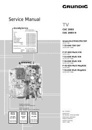
Sub Colour Adjustment<br />
1. Receive a PAL colour bar signal.<br />
2. Connect an oscilloscope to Pin 3 of CN504 [A Board].<br />
3. Enter into the ‘Service’ service menu.<br />
4. Adjust the ‘Sub Colour’ data so that the Cyan, Magenta and<br />
Blue colour bars are of equal levels as indicated below.<br />
Note:<br />
Ensure that no signal is applied to the Antenna socket while<br />
carrying out the following IF adjustments.<br />
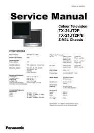
Tuner AGC Adjustment<br />
B-Out Waveform<br />
1. Set the “AGC adjust” register value :<br />
• For destination France set the value to 6.<br />
• All other destinations set the value to 0.<br />
Same Level<br />
2. Receive a signal of 64dBuV / 75 ohm terminated [62dBuV / 75<br />
ohms for B model] via the tuner antenna socket.<br />
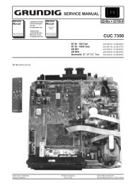
3. Connect a voltmeter to pin1 of TU101 [print side of A Board] or<br />
to the AGC pin of CN001 [mount side of A Board].<br />
4. Confirm that the AGC voltage is 3.5volts +/- 0.3volts.<br />
5. If adjustment is required, enter into the ‘Test Menu’.<br />
6. Select the ‘AGC Adjust’ menu item.<br />
7. Adjust the data using the left and right arrow buttons on the<br />
Remote Commander to obtain a voltage of 3.5V +/- 0.3V.<br />
21<br />
[ Print side of A board ]<br />
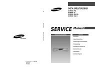
Deflection System Adjustment<br />
1. Enter into the ‘Geometry’ service menu.<br />
2. Select and adjust each item in order to obtain the optimum image.<br />
GEOMETRY<br />
Left-HBlk<br />
Right-HBlk<br />
V-Angle<br />
V-Bow<br />
H-Centre<br />
H-Size<br />
Pin-Amp<br />
U-Corner-Pin<br />
L-Corner-Pin<br />
Pin<br />
Phase<br />
V-Linearity<br />
V-Size<br />
S-Correction<br />
V-Centre<br />
V-Zoom<br />
( 0,<br />
15)<br />
( 0,<br />
15)<br />
( 0,<br />
63)<br />
( 0,<br />
63)<br />
( 0,<br />
63)<br />
( 0,<br />
63)<br />
( 0,<br />
63)<br />
( 0,<br />
63)<br />
( 0,<br />
63)<br />
( 0,<br />
63)<br />
( 0,<br />
63)<br />
( 0,<br />
63)<br />
( 0,<br />
63)<br />
( 0,<br />
63)<br />
( 0,<br />
63)<br />
13<br />
9<br />
Adj<br />
Adj<br />
Adj<br />
Adj<br />
Adj<br />
Adj<br />
Adj<br />
Adj<br />
Adj<br />
Adj<br />
Adj<br />
Adj<br />
25