Create successful ePaper yourself
Turn your PDF publications into a flip-book with our unique Google optimized e-Paper software.
SERVICE MANUAL FE-2 CHASSIS<br />
MODEL COMMANDER DEST CHASSIS NO.<br />
KV-21LT1B RM-887 French SCC-Q54C-A<br />
KV-21LT1E RM-887 Spanish SCC-Q53C-A<br />
KV-21LT1K RM-887 OIRT SCC-Q51C-A<br />
KV-21LT1U RM-887 UK SCC-Q52C-A<br />
KV-21LT1<br />
1<br />
RM-889<br />
RM-887<br />
MODEL COMMANDER DEST CHASSIS NO.<br />
KV-21FT2K RM-887 OIRT SCC-Q51E-A<br />
KV-21FT2
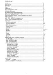
TABLE OF CONTENTS<br />
Section Title Page Section Title Page<br />
Specifications .................... 3<br />
Connectors .................... 5<br />
Self Diagnostic Software .................... 6<br />
1. GENERAL<br />
Switching On the TV and<br />
Automatically Tuning .................... 7<br />
Introducing the Menu System .................... 8<br />
Teletext .................... 10<br />
Connecting Optional Equipment.................... 10<br />
Using Optional Equipment .................... 10<br />
Troubleshooting .................... 11<br />
2. DISASSEMBLY<br />
KV-21LT1<br />
2-1. Rear Cover Removal .................... 12<br />
2-2. A Board PWB Removal 1 .................... 12<br />
2-3. A Board PWB Removal 2 .................... 12<br />
2-4. Service Position .................... 12<br />
2-5. Wire Dressing .................... 12<br />
2-6. Picture Tube Removal .................... 13<br />
KV-21FT2<br />
2-7. Rear Cover Removal .................... 14<br />
2-8. Chassis Removal .................... 14<br />
2-9. Service Position .................... 14<br />
2-10. Wire Dressing .................... 14<br />
2-11. Picture Tube Removal .................... 15<br />
CAUTION<br />
SHORT CIRCUIT THE ANODE OF THE PICTURE TUBE AND THE<br />
ANODE CAP TO THE METAL CHASSIS, CRT SHIELD, OR THE<br />
CARBON PAINTED ON THE CRT, AFTER REMOVAL OF THE<br />
ANODE CAP.<br />
WARNING !!<br />
AN ISOLATION TRANSFORMER SHOULD BE USED DURING ANY<br />
SERVICE WORK TO AVOID POSSIBLE SHOCK HAZARD DUE TO<br />
LIVE CHASSIS, THE CHASSIS OF THIS RECEIVER IS DIRECTLY<br />
CONNECTED TO THE POWER LINE.<br />
SAFETY-RELATED COMPONENT WARNING !!<br />
COMPONENTS IDENTIFIED BY SHADING AND MARKED £ ON<br />
THE SCHEMATIC DIAGRAMS, EXPLODED VIEWS AND IN THE<br />
PARTS LIST ARE CRITICAL FOR SAFE OPERATION. REPLACE<br />
THESE COMPONENTS WITH SONY PARTS WHOSE PART<br />
NUMBERS APPEAR AS SHOWN IN THIS MANUAL OR IN<br />
SUPPLEMENTS PUBLISHED BY SONY.<br />
2<br />
3. SET-UP ADJUSTMENTS<br />
3-1. Beam Landing .................... 16<br />
3-2. Convergence .................... 17<br />
3-3. Focus Adjustment .................... 19<br />
3-4. Screen (G2), White Balance .................... 19<br />
4. CIRCUIT ADJUSTMENTS<br />
4-1. Electrical Adjustments .................... 20<br />
4-2. Test Mode 2 .................... 22<br />
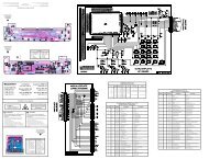
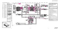
5. DIAGRAMS<br />
5-1. Circuit Board Location .................... 24<br />
5-2. Block Diagrams .................... 25<br />
5-3. Schematic Diagrams and<br />
Printed Wiring Boards .................... 24<br />
* C Board .................... 29<br />
* A Board .................... 31<br />
5-4. Semiconductors .................... 39<br />
5-5. IC Blocks .................... 41<br />
6. EXPLODED VIEWS<br />
6-1. Chassis (KV-21LT1) .................... 42<br />
Chassis (KV-21FT2) .................... 44<br />
6-2. Picture Tube(KV-21LT1) .................... 43<br />
Picture Tube(KV-21FT2) .................... 45<br />
7. ELECTRICAL PARTS LIST .................... 46<br />
ATTENTION<br />
APRES AVOIR DECONNECTE LE CAP DE’LANODE,<br />
COURT-CIRCUITER L’ANODE DU TUBE CATHODIQUE ET CELUI<br />
DE L’ANODE DU CAP AU CHASSIS METALLIQUE DE L’APPAREIL,<br />
OU AU COUCHE DE CARBONE PEINTE SUR LE TUBE<br />
CATHODIQUE OU AU BLINDAGE DU TUBE CATHODIQUE.<br />
ATTENTION !!<br />
AFIN D’EVITER TOUT RISQUE D’ELECTROCUTION PROVENANT<br />
D’UN CHÁSSIS SOUS TENTION, UN TRANSFORMATEUR<br />
D’ISOLEMENT DOIT ETRE UTILISÈ LORS DE TOUT DÈPANNAGE<br />
LE CHÁSSIS DE CE RÈCEPTEUR EST DIRECTMENT RACCORDÈ<br />
Á L’ALIMENTATION SECTEUR.<br />
ATTENTION AUX COMPOSANTS RELATIFS Á<br />
LA SECURITÈ!!<br />
LES COMPOSANTS IDENTIFIÈS PAR UNE TRAME ET PAR UNE<br />
MARQUE £ SUR LES SCHÈMAS DE PRINCIPE, LES VUES<br />
EXPLOSÈES ET LES LISTES DE PIECES SONT D’UNE IMPOR-<br />
TANCE CRITIQUE POUR LA SÈCURITÈ DU FONCTIONNEMENT,<br />
NE LES REMPLACER QUE PAR DES COMPSANTS SONY DONT LE<br />
NUMÈRO DE PIÈCE EST INDIQUÈ DANS LE PRÈSENT MANUEL<br />
OU DANS DES SUPPLÈMENTS PUBLIÈS PAR SONY.
3<br />
L<br />
E<br />
D<br />
O<br />
M<br />
M<br />
E<br />
T<br />
I m<br />
e<br />
t<br />
s<br />
y<br />
S<br />
n<br />
o<br />
i<br />
s<br />
i<br />
v<br />
e<br />
l<br />
e<br />
T e<br />
g<br />
a<br />
r<br />
e<br />
v<br />
o<br />
C<br />
l<br />
e<br />
n<br />
n<br />
a<br />
h<br />
C m<br />
e<br />
t<br />
s<br />
y<br />
S<br />
r<br />
o<br />
l<br />
o<br />
C<br />
h<br />
c<br />
n<br />
e<br />
r<br />
F I<br />
,<br />
L<br />
,<br />
H<br />
/<br />
G<br />
/<br />
B<br />
0<br />
1<br />
F<br />
-<br />
2<br />
F<br />
,<br />
2<br />
1<br />
E<br />
-<br />
2<br />
E<br />
:<br />
F<br />
H<br />
V<br />
9<br />
6<br />
E<br />
-<br />
1<br />
2<br />
E<br />
:<br />
F<br />
H<br />
U<br />
Q<br />
-<br />
B<br />
,<br />
0<br />
2<br />
S<br />
-<br />
1<br />
S<br />
,<br />
3<br />
0<br />
S<br />
-<br />
1<br />
0<br />
S<br />
:<br />
V<br />
T<br />
E<br />
L<br />
B<br />
A<br />
C<br />
1<br />
4<br />
S<br />
-<br />
1<br />
2<br />
S<br />
:<br />
R<br />
E<br />
P<br />
Y<br />
H<br />
9<br />
6<br />
F<br />
-<br />
1<br />
2<br />
F<br />
,<br />
0<br />
1<br />
F<br />
-<br />
2<br />
0<br />
F<br />
L<br />
9<br />
6<br />
B<br />
-<br />
1<br />
2<br />
B<br />
:<br />
F<br />
H<br />
U<br />
I<br />
M<br />
A<br />
C<br />
E<br />
S<br />
,<br />
L<br />
A<br />
P<br />
8<br />
5<br />
.<br />
3<br />
C<br />
S<br />
T<br />
N<br />
,<br />
3<br />
4<br />
.<br />
4<br />
C<br />
S<br />
T<br />
N<br />
)<br />
N<br />
I<br />
O<br />
E<br />
D<br />
I<br />
V<br />
(<br />
h<br />
s<br />
i<br />
n<br />
a<br />
p<br />
S H<br />
/<br />
G<br />
/<br />
B<br />
2<br />
1<br />
E<br />
-<br />
2<br />
E<br />
:<br />
F<br />
H<br />
V<br />
9<br />
6<br />
E<br />
-<br />
1<br />
2<br />
E<br />
:<br />
F<br />
H<br />
U<br />
0<br />
2<br />
S<br />
-<br />
1<br />
S<br />
,<br />
3<br />
0<br />
S<br />
-<br />
1<br />
0<br />
S<br />
:<br />
V<br />
T<br />
E<br />
L<br />
B<br />
A<br />
C<br />
1<br />
4<br />
S<br />
-<br />
1<br />
2<br />
S<br />
:<br />
R<br />
E<br />
P<br />
Y<br />
H<br />
M<br />
A<br />
C<br />
E<br />
S<br />
,<br />
L<br />
A<br />
P<br />
8<br />
5<br />
.<br />
3<br />
C<br />
S<br />
T<br />
N<br />
,<br />
3<br />
4<br />
.<br />
4<br />
C<br />
S<br />
T<br />
N<br />
)<br />
N<br />
I<br />
O<br />
E<br />
D<br />
I<br />
V<br />
(<br />
T<br />
R<br />
I<br />
O K<br />
/<br />
D<br />
,<br />
H<br />
/<br />
G<br />
/<br />
B<br />
2<br />
1<br />
R<br />
-<br />
1<br />
0<br />
R<br />
,<br />
2<br />
1<br />
E<br />
-<br />
2<br />
E<br />
:<br />
F<br />
H<br />
V<br />
9<br />
6<br />
R<br />
-<br />
1<br />
2<br />
R<br />
,<br />
9<br />
6<br />
E<br />
-<br />
1<br />
2<br />
E<br />
:<br />
F<br />
H<br />
U<br />
0<br />
2<br />
S<br />
-<br />
1<br />
S<br />
,<br />
3<br />
0<br />
S<br />
-<br />
1<br />
0<br />
S<br />
:<br />
V<br />
T<br />
E<br />
L<br />
B<br />
A<br />
C<br />
1<br />
4<br />
S<br />
-<br />
1<br />
2<br />
S<br />
:<br />
R<br />
E<br />
P<br />
Y<br />
H<br />
M<br />
A<br />
C<br />
E<br />
S<br />
,<br />
L<br />
A<br />
P<br />
8<br />
5<br />
.<br />
3<br />
C<br />
S<br />
T<br />
N<br />
,<br />
3<br />
4<br />
.<br />
4<br />
C<br />
S<br />
T<br />
N<br />
)<br />
N<br />
I<br />
O<br />
E<br />
D<br />
I<br />
V<br />
(<br />
K<br />
U I 9<br />
6<br />
B<br />
-<br />
1<br />
2<br />
B<br />
F<br />
H<br />
U<br />
:<br />
I<br />
M<br />
A<br />
C<br />
E<br />
S<br />
,<br />
L<br />
A<br />
P<br />
8<br />
5<br />
.<br />
3<br />
C<br />
S<br />
T<br />
N<br />
,<br />
3<br />
4<br />
.<br />
4<br />
C<br />
S<br />
T<br />
N<br />
)<br />
N<br />
I<br />
O<br />
E<br />
D<br />
I<br />
V<br />
(<br />
l<br />
e<br />
d<br />
o<br />
M K<br />
2<br />
T<br />
F<br />
1<br />
2<br />
-<br />
V<br />
K B<br />
1<br />
T<br />
L<br />
1<br />
2<br />
-<br />
V<br />
K E<br />
1<br />
T<br />
L<br />
1<br />
2<br />
-<br />
V<br />
K K<br />
1<br />
T<br />
L<br />
1<br />
2<br />
-<br />
V<br />
K U<br />
1<br />
T<br />
L<br />
1<br />
2<br />
-<br />
V<br />
K<br />
n<br />
o<br />
i<br />
t<br />
p<br />
m<br />
u<br />
s<br />
n<br />
o<br />
C<br />
r<br />
e<br />
w<br />
o<br />
P W<br />
5<br />
5 W<br />
5<br />
5 W<br />
5<br />
5 W<br />
5<br />
5 W<br />
6<br />
7<br />
e<br />
b<br />
u<br />
T<br />
e<br />
r<br />
u<br />
t<br />
c<br />
i<br />
P<br />
n<br />
o<br />
r<br />
t<br />
i<br />
n<br />
i<br />
r<br />
T<br />
D<br />
F<br />
y<br />
a<br />
l<br />
p<br />
s<br />
i<br />
D<br />
t<br />
a<br />
l<br />
F<br />
)<br />
s<br />
e<br />
h<br />
c<br />
n<br />
i<br />
1<br />
2<br />
(<br />
m<br />
c<br />
5<br />
5<br />
.<br />
x<br />
o<br />
r<br />
p<br />
p<br />
A<br />
d<br />
e<br />
r<br />
u<br />
s<br />
a<br />
e<br />
m<br />
e<br />
r<br />
u<br />
t<br />
c<br />
i<br />
p<br />
m<br />
c<br />
1<br />
5<br />
.<br />
x<br />
o<br />
r<br />
p<br />
p<br />
A<br />
(<br />
)<br />
y<br />
l<br />
l<br />
a<br />
n<br />
o<br />
g<br />
a<br />
i<br />
d<br />
n<br />
o<br />
i<br />
t<br />
c<br />
e<br />
l<br />
f<br />
e<br />
d<br />
e<br />
e<br />
r<br />
g<br />
e<br />
d<br />
0<br />
1<br />
1<br />
t<br />
u<br />
p<br />
t<br />
u<br />
o<br />
d<br />
n<br />
u<br />
o<br />
S<br />
:<br />
U<br />
1<br />
T<br />
L<br />
1<br />
2<br />
/<br />
K<br />
1<br />
T<br />
L<br />
1<br />
2<br />
/<br />
E<br />
1<br />
T<br />
L<br />
1<br />
2<br />
/<br />
B<br />
1<br />
T<br />
L<br />
1<br />
2<br />
)<br />
r<br />
e<br />
w<br />
o<br />
P<br />
c<br />
i<br />
s<br />
u<br />
M<br />
(<br />
W<br />
8<br />
x<br />
1<br />
)<br />
o<br />
n<br />
o<br />
M<br />
S<br />
M<br />
R<br />
(<br />
W<br />
4<br />
x<br />
1<br />
:<br />
K<br />
2<br />
T<br />
F<br />
1<br />
2<br />
)<br />
r<br />
e<br />
w<br />
o<br />
P<br />
c<br />
i<br />
s<br />
u<br />
M<br />
(<br />
W<br />
6<br />
x<br />
2<br />
)<br />
o<br />
n<br />
o<br />
M<br />
S<br />
M<br />
R<br />
(<br />
W<br />
3<br />
x<br />
2<br />
]<br />
R<br />
A<br />
E<br />
R<br />
[<br />
s<br />
l<br />
a<br />
n<br />
i<br />
m<br />
r<br />
e<br />
T<br />
t<br />
u<br />
p<br />
t<br />
u<br />
O<br />
/<br />
t<br />
u<br />
p<br />
n<br />
I s<br />
t<br />
n<br />
e<br />
m<br />
e<br />
r<br />
i<br />
u<br />
q<br />
e<br />
R<br />
r<br />
e<br />
w<br />
o<br />
P V<br />
0<br />
4<br />
2<br />
-<br />
0<br />
2<br />
2<br />
r<br />
o<br />
t<br />
c<br />
e<br />
n<br />
n<br />
o<br />
c<br />
o<br />
r<br />
u<br />
E<br />
n<br />
i<br />
p<br />
-<br />
1<br />
2<br />
:<br />
1<br />
)<br />
d<br />
r<br />
a<br />
d<br />
n<br />
a<br />
t<br />
s<br />
C<br />
E<br />
L<br />
E<br />
N<br />
E<br />
C<br />
(<br />
.<br />
s<br />
l<br />
a<br />
n<br />
g<br />
i<br />
s<br />
o<br />
e<br />
d<br />
i<br />
V<br />
d<br />
n<br />
a<br />
o<br />
i<br />
d<br />
u<br />
A<br />
r<br />
o<br />
f<br />
s<br />
t<br />
u<br />
p<br />
n<br />
I<br />
.<br />
B<br />
G<br />
R<br />
r<br />
o<br />
f<br />
s<br />
t<br />
u<br />
p<br />
n<br />
I<br />
.<br />
s<br />
l<br />
a<br />
n<br />
g<br />
i<br />
s<br />
o<br />
i<br />
d<br />
u<br />
A<br />
d<br />
n<br />
a<br />
o<br />
e<br />
d<br />
i<br />
V<br />
V<br />
T<br />
f<br />
o<br />
s<br />
t<br />
u<br />
p<br />
t<br />
u<br />
O<br />
s<br />
n<br />
o<br />
i<br />
s<br />
n<br />
e<br />
m<br />
i<br />
D<br />
:<br />
U<br />
1<br />
T<br />
L<br />
1<br />
2<br />
/<br />
K<br />
1<br />
T<br />
L<br />
1<br />
2<br />
/<br />
E<br />
1<br />
T<br />
L<br />
1<br />
2<br />
/<br />
B<br />
1<br />
T<br />
L<br />
1<br />
2<br />
m<br />
m<br />
7<br />
8<br />
4<br />
x<br />
8<br />
7<br />
4<br />
x<br />
4<br />
1<br />
5<br />
x<br />
o<br />
r<br />
p<br />
p<br />
A<br />
:<br />
K<br />
2<br />
T<br />
F<br />
1<br />
2<br />
m<br />
m<br />
7<br />
7<br />
4<br />
x<br />
0<br />
8<br />
4<br />
x<br />
8<br />
8<br />
4<br />
x<br />
o<br />
r<br />
p<br />
p<br />
A<br />
]<br />
T<br />
N<br />
O<br />
R<br />
F<br />
[<br />
s<br />
l<br />
a<br />
n<br />
i<br />
m<br />
r<br />
e<br />
T<br />
t<br />
u<br />
p<br />
t<br />
u<br />
O<br />
/<br />
t<br />
u<br />
p<br />
n<br />
I t<br />
h<br />
g<br />
i<br />
e<br />
W<br />
:<br />
U<br />
1<br />
T<br />
L<br />
1<br />
2<br />
/<br />
K<br />
1<br />
T<br />
L<br />
1<br />
2<br />
/<br />
E<br />
1<br />
T<br />
L<br />
1<br />
2<br />
/<br />
B<br />
1<br />
T<br />
L<br />
1<br />
2<br />
g<br />
k<br />
4<br />
2<br />
x<br />
o<br />
r<br />
p<br />
p<br />
A<br />
g<br />
k<br />
1<br />
.<br />
6<br />
2<br />
x<br />
o<br />
r<br />
p<br />
p<br />
A<br />
:<br />
K<br />
2<br />
T<br />
F<br />
1<br />
2<br />
t<br />
u<br />
p<br />
n<br />
i<br />
o<br />
e<br />
d<br />
i<br />
V k<br />
c<br />
a<br />
j<br />
o<br />
n<br />
o<br />
h<br />
p s<br />
e<br />
i<br />
r<br />
o<br />
s<br />
s<br />
e<br />
c<br />
c<br />
A<br />
d<br />
e<br />
i<br />
l<br />
p<br />
p<br />
u<br />
S<br />
)<br />
1<br />
(<br />
r<br />
e<br />
d<br />
n<br />
a<br />
m<br />
m<br />
o<br />
C<br />
e<br />
t<br />
o<br />
m<br />
e<br />
R<br />
7<br />
8<br />
8<br />
-<br />
M<br />
R<br />
)<br />
2<br />
(<br />
y<br />
r<br />
e<br />
t<br />
t<br />
a<br />
b<br />
6<br />
R<br />
d<br />
e<br />
t<br />
a<br />
n<br />
g<br />
i<br />
s<br />
e<br />
d<br />
C<br />
E<br />
I<br />
t<br />
u<br />
p<br />
n<br />
i<br />
o<br />
i<br />
d<br />
u<br />
A k<br />
c<br />
a<br />
j<br />
o<br />
n<br />
o<br />
h<br />
p s<br />
e<br />
r<br />
u<br />
t<br />
a<br />
e<br />
F<br />
r<br />
e<br />
h<br />
t<br />
O<br />
,<br />
k<br />
n<br />
i<br />
l<br />
t<br />
r<br />
a<br />
m<br />
S<br />
,<br />
r<br />
e<br />
m<br />
i<br />
T<br />
p<br />
e<br />
e<br />
l<br />
S<br />
,<br />
t<br />
x<br />
e<br />
t<br />
e<br />
l<br />
e<br />
T<br />
n<br />
o<br />
i<br />
t<br />
c<br />
e<br />
t<br />
e<br />
d<br />
o<br />
t<br />
u<br />
A<br />
m<br />
e<br />
t<br />
s<br />
y<br />
s<br />
V<br />
T<br />
k<br />
c<br />
a<br />
j<br />
e<br />
n<br />
o<br />
h<br />
p<br />
d<br />
a<br />
e<br />
H k<br />
c<br />
a<br />
j<br />
i<br />
n<br />
i<br />
m<br />
o<br />
e<br />
r<br />
e<br />
t<br />
s<br />
m<br />
e<br />
t<br />
s<br />
y<br />
s<br />
l<br />
o<br />
r<br />
t<br />
n<br />
o<br />
c<br />
e<br />
t<br />
o<br />
m<br />
e<br />
R l<br />
o<br />
r<br />
t<br />
n<br />
o<br />
c<br />
d<br />
e<br />
r<br />
a<br />
r<br />
f<br />
n<br />
I<br />
s<br />
t<br />
n<br />
e<br />
m<br />
e<br />
r<br />
i<br />
u<br />
q<br />
e<br />
r<br />
r<br />
e<br />
w<br />
o<br />
P<br />
c<br />
d<br />
V<br />
3<br />
n<br />
o<br />
i<br />
t<br />
a<br />
n<br />
g<br />
i<br />
s<br />
e<br />
d<br />
C<br />
E<br />
I<br />
s<br />
e<br />
i<br />
r<br />
e<br />
t<br />
t<br />
a<br />
b<br />
2<br />
)<br />
A<br />
A<br />
e<br />
z<br />
i<br />
s<br />
(<br />
6<br />
R<br />
.<br />
e<br />
c<br />
i<br />
t<br />
o<br />
n<br />
t<br />
u<br />
o<br />
h<br />
t<br />
i<br />
w<br />
e<br />
g<br />
n<br />
a<br />
h<br />
c<br />
o<br />
t<br />
t<br />
c<br />
e<br />
j<br />
b<br />
u<br />
s<br />
e<br />
r<br />
a<br />
s<br />
n<br />
o<br />
i<br />
t<br />
a<br />
c<br />
i<br />
f<br />
i<br />
c<br />
e<br />
p<br />
s<br />
d<br />
n<br />
a<br />
n<br />
g<br />
i<br />
s<br />
e<br />
D
Model<br />
Name<br />
Item<br />
KV-21FT2K KV-21LT1B KV-21LT1E KV-21LT1K KV-21LT1U<br />
Pal Comb<br />
OFF OFF OFF OFF OFF<br />
PIP OFF OFF OFF OFF OFF<br />
RGB Priority<br />
OFF ON ON OFF ON<br />
Woofer Box<br />
OFF OFF OFF OFF OFF<br />
Scart 1<br />
ON ON ON ON ON<br />
Scart 2<br />
OFF OFF OFF OFF OFF<br />
Front in<br />
( 3)<br />
OFF OFF OFF OFF OFF<br />
Scart 4<br />
OFF OFF OFF OFF OFF<br />
Projector OFF OFF OFF OFF OFF<br />
AKB in<br />
16:<br />
9 mode<br />
OFF OFF OFF OFF OFF<br />
Norm B/<br />
G<br />
ON ON ON ON OFF<br />
Norm I<br />
OFF ON OFF OFF ON<br />
Norm D/<br />
K<br />
ON OFF ON OFF OFF<br />
Norm AUS<br />
OFF OFF OFF OFF OFF<br />
Norm L<br />
OFF ON OFF OFF OFF<br />
Norm SAT<br />
OFF OFF OFF OFF OFF<br />
Norm M<br />
OFF OFF OFF OFF OFF<br />
Teletext ON ON ON ON ON<br />
Nicam Stereo<br />
OFF OFF OFF OFF OFF<br />
WARNING (UK Models only)<br />
The flexible mains lead is supplied connected to a B.S. 1363 fused plug<br />
having a fuse of 5 AMP rating. Should the fuse need to be replaced, use<br />
a 5 AMP FUSE approved by ASTA to BS 1362, ie one that carries the<br />
ASA T mark.<br />
IF THE PLUG SUPPLIED WITH THIS APPLIANCE IS NOT SUITABLE<br />
FOR THE OUTLET SOCKETS IN YOUR HOME, IT SHOULD BE CUT<br />
OFF AND AN APPROPRIATE PLUG FITTED. THE PLUG SEVERED<br />
FROM THE MAINS LEAD MUST BE DESTROYED AS A PLUG WITH<br />
BARED WIRES IS DANGEROUS IF ENGAGED IN A LIVE SOCKET.<br />
When an alternative type of plug is used, it should be fitted with a<br />
5 AMP FUSE, otherwise the circuit should be protected by a 5 AMP<br />
FUSE at the distribution board.<br />
4<br />
How to replace the fuse.<br />
Open the fuse compartment with<br />
a screwdriver blade and replace<br />
the fuse.<br />
FUSE
21 pin connector<br />
21<br />
19<br />
17<br />
15<br />
13<br />
11<br />
9<br />
7<br />
5<br />
3<br />
1<br />
Rear Connection Panel<br />
KV-21LT1<br />
Front Connection Panel<br />
20<br />
18<br />
16<br />
14<br />
12<br />
10<br />
8<br />
6<br />
4<br />
2<br />
Pin No 1 2 4 Signal Signal level<br />
1 Audio output B<br />
(right)<br />
2<br />
3<br />
5<br />
Audio output B<br />
(right)<br />
Audio output A<br />
(left)<br />
4 Ground (audio)<br />
5 Ground (blue)<br />
6 Audio input A<br />
(left)<br />
Standard level : 0.5V rms<br />
Output impedence : Less than 1kohm*<br />
Standard level : 0.5V rms<br />
Output impedence : More than 10kohm*<br />
Standard level : 0.5V rms<br />
Output impedence : Less than 1kohm*<br />
Standard level : 0.5V rms<br />
Output impedence : More than 10kohm*<br />
7 Blue input 0.7 +/- 3dB, 75 ohms positive<br />
8 Function select<br />
(AV control)<br />
9 Ground (green)<br />
10 Open<br />
High state (9.5-12V) : Part mode<br />
Low state (0-2V) : TV mode<br />
Input impedence : More than 10K ohms<br />
Input capacitance : Less than 2nF<br />
11 Green Green signal : 0.7 +/- 3dB, 75 ohms,<br />
positive<br />
12 Open<br />
13 Ground (red)<br />
14 Ground (blanking)<br />
15<br />
_ _ Red input 0.7 +/- 3dB, 75 ohms, positive<br />
_ (S signal Chroma<br />
input)<br />
16 Blanking input<br />
(Ys signal)<br />
17 Ground (video<br />
output)<br />
18 Ground (video<br />
input)<br />
0.3 +/- 3dB, 75 ohms, positive<br />
High state (1-3V) Low state (0-0.4V)<br />
Input impedence : 75 ohms<br />
19 Video output 1V +/- 3dB, 75ohms, positive sync 0.3V<br />
(-3+10dB)<br />
20<br />
_ _ Video input 1V +/- 3dB, 75ohms, positive sync 0.3V<br />
(-3+10dB)<br />
_ Video input<br />
Y (S signal)<br />
21 Common ground<br />
(plug, shield)<br />
1V +/- 3dB, 75ohms, positive sync 0.3V<br />
(-3+10dB)<br />
Connected Not Connected (open) * at 20Hz - 20kHz<br />
KV-21FT2<br />
KV-21LT1 KV-21FT2
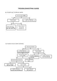
FE-2 SELF DIAGNOSTIC SOFTWARE<br />
The identification of errors within the FE-2 chassis is triggered in one of two ways :- 1: Busy or 2: Device failure to respond to IIC. In the event of<br />
one of these situations arising the software will first try to release the bus if busy (Failure to do so will report with a continuous flashing LED) and<br />
then communicate with each device in turn to establish if a device is faulty. If a device is found to be faulty the relevant device number will be<br />
displayed through the LED (Series of flashes which must be counted) See table 1., non fatal errors are reported using this method.<br />
Each time the software detects an error it is stored within the NVM. See Table 2.<br />
Table 1 How to enter into Table 2<br />
Error<br />
Message<br />
LED<br />
Code<br />
Noerror 00<br />
Reserved 01<br />
OCP ( Over<br />
Current<br />
Protection<br />
)<br />
02<br />
Reserved 03<br />
NoVertical Sync<br />
04<br />
Unstable AKB<br />
05<br />
IIC bus<br />
clock<br />
and/<br />
or<br />
data<br />
lines<br />
low<br />
at<br />
power<br />
on<br />
06<br />
NVM no<br />
IIC<br />
bus<br />
acknowledge<br />
at<br />
power<br />
on<br />
07<br />
Not Used<br />
08<br />
Tuner no<br />
acknowledge<br />
at<br />
power<br />
on<br />
09<br />
Not used<br />
10<br />
Jungle controller<br />
no<br />
acknowledge<br />
at<br />
Power<br />
ON<br />
11<br />
Flash Timing Example : e.g. error number 3<br />
StBy LED<br />
ON ON ON<br />
OFF OFF<br />
6<br />
1. Turn on the main power switch of the TV set and enter into the<br />
‘Stanby Mode’.<br />
2. Press the following sequence of buttons on the Remote<br />
Commander.<br />
i+ 5 -<br />
(ON SCREEN (DIGIT 5) (VOLUME -) (TV)<br />
DISPLAY)<br />
3. The following table will be displayed indicating the error count.<br />
Table 2<br />
ERROR<br />
MENU<br />
E02<br />
E03<br />
E04<br />
E05<br />
E06<br />
E07<br />
E08<br />
E09<br />
E10<br />
E11<br />
WORKING<br />
TIME<br />
HOURS<br />
MINUTES<br />
OCP<br />
OVP<br />
N/<br />
A<br />
VSYNC<br />
IKR<br />
IIC<br />
NVM<br />
JUNGLE<br />
TUNER<br />
SOUNDP<br />
8V<br />
( 0,<br />
255)<br />
( 0,<br />
255)<br />
( 0,<br />
255)<br />
( 0,<br />
255)<br />
( 0,<br />
255)<br />
( 0,<br />
255)<br />
( 0,<br />
255)<br />
( 0,<br />
255)<br />
( 0,<br />
255)<br />
( 0,<br />
255)<br />
Note: To clear the error count data press ‘80’ on the Remote<br />
commander.<br />
0<br />
0<br />
0<br />
0<br />
0<br />
0<br />
0<br />
0<br />
0<br />
0<br />
0<br />
0
The operating instructions mentioned here are partial abstracts from the ‘Operating<br />
Instruction Manual’. The page numbers of the ‘Operating Instruction Manual’ remain<br />
as in the manual.<br />
Please confirm that<br />
aerial is connected<br />
Confirm<br />
5 A new menu appears on the screen asking you to check<br />
that the aerial is connected. Ensure the aerial is connected<br />
and then press the OK button to start the automatic<br />
tuning.<br />
Switching On the TV and Automatically Tuning<br />
OK<br />
The TV starts to automatically search and store all<br />
available channels (TV Broadcast) for you.<br />
K<br />
Auto Tuning<br />
Programme: 01<br />
System: B/G<br />
Channel: C21<br />
This procedure could take some minutes. Please be<br />
patient and do not press any button. Otherwise the<br />
automatic tuning will not be completed.<br />
The first time you switch on your TV, a sequence of menu screen appear on the TV enabling<br />
you to: 1) choose the language of the menu screen, 2) choose the country in which you wish<br />
to operate the TV, 3) search and store all available channels (TV Broadcast) and 4) change<br />
the order in which the channels (TV Broadcast) appear on the screen.<br />
However, if you need to change the language menu, change or repeat the tuning (e.g. when<br />
you move house) or rearrange again the order of the channels afterwards, you can do that<br />
by selecting the appropriate menu in the (Set Up). For more information, refer to the<br />
“Menu Guide” section of this instruction manual. You can also do that by pressing the<br />
Auto Start Up Button on the TV set.<br />
Searching...<br />
Programme Sorting<br />
K<br />
Programme:<br />
01 TVE<br />
02 TVE2<br />
03 TV3<br />
04 C33<br />
05 C27<br />
6 After all available channels are captioned and stored,<br />
the Programme Sorting menu appears automatically<br />
on the screen enabling you to change the order in<br />
which the channels appear on the screen.<br />
Connect the TV plug to the mains socket (220-240V AC,<br />
50Hz)<br />
Press the on/off button on the TV set to turn on the TV.<br />
The first time you press this button, a Language menu<br />
displays automatically on the TV screen.<br />
1<br />
SECTION 1 GENERAL<br />
06 C58<br />
OK<br />
Select channel:<br />
Exit: MENU<br />
a) If you do not wish to change the channel order, go to<br />
step 7.<br />
Programme Sorting<br />
b) If you wish to change the channel order:<br />
1 Press the or button to select the programme<br />
number with the channel (TV Broadcast) you wish<br />
to rearrange, then press the button.<br />
GB<br />
Programme:<br />
01 TVE<br />
02 TVE2<br />
03 TV3<br />
04 C33<br />
05 C27<br />
06 C58 05 C27<br />
7<br />
Language<br />
2<br />
K<br />
OK<br />
Select new position:<br />
Exit: MENU<br />
2 Press the or button to select the new<br />
programme number position for your selected<br />
channel (TV Broadcast), then press .<br />
K<br />
English<br />
Español<br />
Français<br />
Italiano<br />
Magyar<br />
Nederlands<br />
Press the or button on the remote control to select<br />
the language, then press the OK button to confirm your<br />
selection. From now on all the menus will appear in the<br />
selected language.<br />
OK<br />
Select Language:<br />
3 Repeat steps b)1 and b)2 if you wish to change<br />
the order of the other channels.<br />
MENU<br />
7 Press the MENU button to remove the menu from the<br />
screen.<br />
K<br />
Country<br />
-<br />
Бългapия<br />
Česká rep.<br />
Magyarország<br />
Polska<br />
România<br />
Select country:<br />
The Country menu appears automatically on the TV<br />
screen. Press the or button to select the country in<br />
which you will operate the TV set, then press the OK<br />
button to confirm your selection.<br />
3<br />
OK<br />
Your TV is now ready for use<br />
Select “-“ instead of a country<br />
• If the country in which you want to use the TV set<br />
does not appear in the list.<br />
• If you do not want your channels (TV Broadcast)<br />
stored in a given channel sequence starting from<br />
programme position 1.<br />
4<br />
K<br />
Do you want to start<br />
automatic tuning?<br />
Yes<br />
No<br />
The Auto Tuning menu appears on the screen. Press the<br />
OK button to select Yes.<br />
OK<br />
First Time Operation<br />
8<br />
continued...<br />
First Time Operation 7
Level 1 Level 2 Level 3 / Function<br />
SLEEP TIMER<br />
The “Sleep Timer” option in the “Timer” menu<br />
allows you to select a time period for the TV to<br />
switch itself automatically into the standby<br />
mode.<br />
Picture Adjustment<br />
Mode: Personal<br />
Contrast<br />
Brightness<br />
Colour<br />
Sharpness<br />
Hue<br />
Reset<br />
Introducing and Using the Menu System<br />
Your TV uses an on-screen menu system to guide you through the operations. Use the<br />
following buttons on the Remote Control to operate the menu system:<br />
OK<br />
To do that: after selecting the option press ,<br />
then press or to set the time period delay<br />
(max. of 4 hours) and finally press OK to store.<br />
1 Press the MENU button to switch the first level menu on. MENU<br />
Timer<br />
Sleep Timer: Off<br />
On Timer: i Off<br />
Timer<br />
Sleep Timer: Off<br />
On Timer: Off<br />
• While watching the TV, you can press the<br />
button on the remote control to display the<br />
time remaining.<br />
• One minute before the TV switches itself into<br />
standby mode, the time remaining is displayed on<br />
the TV screen automatically.<br />
OK<br />
OK<br />
2 • To highlight the desired menu or option, press or .<br />
• To enter to the selected menu or option, press .<br />
K<br />
• To return to the last menu or option, press .<br />
• To alter settings of your selected option, press / / or .<br />
• To confirm and store your selection, press OK.<br />
ON TIMER<br />
The “On Timer” option in the “Timer” menu<br />
allows you to select a time period for the TV to<br />
switch itself automatically on from standby<br />
mode.<br />
Picture Adjustment<br />
Mode: Personal<br />
Contrast<br />
Brightness<br />
Colour<br />
Sharpness<br />
Hue<br />
Reset<br />
MENU<br />
3 Press the MENU button to remove the menu from the screen.<br />
OK<br />
GB<br />
To do that: after selecting the option press ,<br />
then press or to set the time period delay<br />
(max. 12 hours) and press OK to store. Finally<br />
press the standby button on the remote<br />
control. After the selected length of time the TV<br />
switches on automatically.<br />
Timer<br />
Sleep Timer: Off<br />
On Timer: Off<br />
Timer<br />
Sleep Timer: Off<br />
On Timer: Off<br />
Menu Guide<br />
8<br />
• The standby indicator on the TV set flashes<br />
regularly to indicate that “On Timer” is active.<br />
• Any loss of power will cause these settings to be<br />
cleared.<br />
OK<br />
OK<br />
Level 1 Level 2 Level 3 / Function<br />
PICTURE ADJUSTMENT<br />
The “Picture Adjustment” menu allows you to<br />
alter the picture adjustments.<br />
Picture Adjustment<br />
Mode: Personal<br />
Contrast<br />
Brightness<br />
Colour<br />
Sharpness<br />
Hue<br />
Reset<br />
Picture Adjustment<br />
Mode: Personal<br />
Contrast<br />
Brightness<br />
Colour<br />
Sharpness<br />
Hue<br />
Reset<br />
To do that: after selecting the item you want to<br />
alter press , then press repeatedly / /<br />
or to adjust it and finally press OK to<br />
store the new adjustment.<br />
This menu also allows you to customise the<br />
picture mode based on the programme you are<br />
watching:<br />
Personal (for individual settings).<br />
Live (for live broadcast programmes).<br />
Movie (for films).<br />
OK<br />
OK<br />
LANGUAGE / COUNTRY<br />
The “Language/Country” option in the “Set<br />
Up” menu allows you to select the language<br />
that the menus are displayed in. It also allows<br />
you to select the country in which you wish to<br />
operate the TV set.<br />
Picture Adjustment<br />
Mode: Personal<br />
Contrast<br />
Brightness<br />
Colour<br />
Sharpness<br />
Hue<br />
Reset<br />
OK<br />
To do that: after selecting the option, press<br />
and then proceed in the same way as in the<br />
steps 2 and 3 of the section “Switching On the<br />
TV and Automatically Tuning”.<br />
Set Up<br />
Language/Country<br />
Auto Tuning<br />
Programme Sorting<br />
Manual Programme Preset<br />
Advanced Features<br />
Set Up<br />
Language/Country<br />
Auto Tuning<br />
Programme Sorting<br />
Manual Programme Preset<br />
Advanced Features<br />
OK<br />
OK<br />
• Brightness, Colour and Sharpness can only be alterated if “Personal” mode is selected.<br />
• Hue is only available for NTSC colour signal (e.g: USA video tapes).<br />
• Select Reset and press OK to reset the picture to the factory preset levels.<br />
continued...<br />
10 Menu System<br />
continued...<br />
Menu System 9
Level 1 Level 2 Level 3 / Function<br />
Level 1 Level 2 Level 3 / Function<br />
3 After selecting the Channel option, press .<br />
Then press or to select the channel<br />
tuning (“C” for terrestrial channels or “S” for<br />
cable channels). Next press . After that,<br />
press the number buttons to enter directly the<br />
channel number of the TV Broadcast or the<br />
channel of the VCR signal. If you do not<br />
know the channel number, press or to<br />
search for it. When you tune the desired<br />
channel, press OK twice to store.<br />
Picture Adjustment<br />
Mode: Personal<br />
Contrast<br />
Brightness<br />
Colour<br />
Sharpness<br />
Hue<br />
Reset<br />
AUTO TUNING<br />
The “Auto Tuning” option in the “Set Up”<br />
menu allows you to automatically search for<br />
and store all available TV channels.<br />
Picture Adjustment<br />
Mode: Personal<br />
Contrast<br />
Brightness<br />
Colour<br />
Sharpness<br />
Hue<br />
Reset<br />
OK<br />
To do that: after selecting the option, press<br />
and then proceed in the same way as in TV<br />
steps 4 and 5 of the section “Switching On the<br />
TV and Automatically Tuning”.<br />
OK<br />
Set Up<br />
Language/Country<br />
Auto Tuning<br />
Programme Sorting<br />
Manual Programme Preset<br />
Advanced Features<br />
Set Up<br />
Language/Country<br />
Auto Tuning<br />
Programme Sorting<br />
Manual Programme Preset<br />
Advanced Features<br />
Set Up<br />
Language/Country<br />
Auto Tuning<br />
Programme Sorting<br />
Manual Programme Preset<br />
Advanced Features<br />
Set Up<br />
Language/Country<br />
Auto Tuning<br />
Programme Sorting<br />
Manual Programme Preset<br />
Advanced Features<br />
Repeat all the above steps to tune and store more<br />
channels.<br />
OK<br />
OK<br />
OK<br />
OK<br />
Manual Programme Preset<br />
b)Normally the automatic fine tuning (AFT) is<br />
operating, however you can manually fine<br />
tune the TV to obtain a better picture<br />
reception in the case that the picture is<br />
distorted.<br />
01<br />
B/G<br />
C 21<br />
--TVE<br />
On<br />
No<br />
Off<br />
Programme:<br />
System:<br />
Channel:<br />
Label:<br />
AFT:<br />
Skip:<br />
Decoder:<br />
Confirm<br />
OK<br />
PROGRAMME SORTING<br />
The “Programme Sorting” option in the “Set<br />
Up” menu allows you to change the order in<br />
which the channels (TV Broadcast) appear on<br />
the screen.<br />
Picture Adjustment<br />
Mode: Personal<br />
Contrast<br />
Brightness<br />
Colour<br />
Sharpness<br />
Hue<br />
Reset<br />
OK<br />
To do that: while watching the channel (TV<br />
Broadcast) you wish to fine tune, select the<br />
AFT option and press . Next press<br />
or to adjust the fine tuning between -15<br />
and +15. Finally press OK twice to store.<br />
To do that: after selecting the option, press<br />
and then proceed in the same way as in step 6 b)<br />
of the section “Switching On the TV and<br />
Automatically Tuning”.<br />
GB<br />
Set Up<br />
Language/Country<br />
Auto Tuning<br />
Programme Sorting<br />
Manual Programme Preset<br />
Advanced Features<br />
Set Up<br />
Language/Country<br />
Auto Tuning<br />
Programme Sorting<br />
Manual Programme Preset<br />
Advanced Features<br />
c) Skip any unwanted programme numbers<br />
when they are selected with the PROGR +/buttons.<br />
OK<br />
OK<br />
9<br />
To do that: Highlighting the Programme<br />
option, press the PROGR +/- button to select<br />
the programme number you want to skip.<br />
When the programme you want to skip<br />
appears on the screen, select the Skip option<br />
and press . Next press or to select<br />
Yes. Finally press OK twice to confirm and<br />
store.<br />
MANUAL PROGRAMME PRESET<br />
The “Manual Programme Preset” option in the<br />
“Set Up” menu allows you to:<br />
a) Preset channels or a video input source one<br />
by one to the programme order of your<br />
choice. To do that:<br />
Picture Adjustment<br />
Mode: Personal<br />
Contrast<br />
Brightness<br />
Colour<br />
Sharpness<br />
Hue<br />
Reset<br />
OK<br />
1 After selecting the ”Manual Programme<br />
Preset” option, press then with<br />
Programme option highlighted press .<br />
Press or to select on which<br />
programme number you want to preset the<br />
channel (for VCR, select programme number<br />
“0”). Then press .<br />
Set Up<br />
Language/Country<br />
Auto Tuning<br />
Programme Sorting<br />
Manual Programme Preset<br />
Advanced Features<br />
Set Up<br />
Language/Country<br />
Auto Tuning<br />
Programme Sorting<br />
Manual Programme Preset<br />
Advanced Features<br />
To cancel this function afterwards, select “No”<br />
instead of “Yes” in the step above.<br />
OK<br />
OK<br />
d) Label a channel using up to five characters.<br />
To do that: Highlighting the Programme<br />
option, press the PROGR +/- button to select<br />
the programme number with the channel<br />
you wish to name. When the programme you<br />
want to name appears on the screen, select<br />
the Label option and press . Next<br />
press or to select a letter, number or<br />
“-“ for a blank. Press to confirm this<br />
character. Select the other four characters in<br />
the same way. After selecting all the<br />
characters, press OK twice to store.<br />
Manual Programme Preset<br />
01<br />
B/G<br />
C 21<br />
--TVE<br />
On<br />
No<br />
Off<br />
Programme:<br />
System:<br />
Channel:<br />
Label:<br />
AFT:<br />
Skip:<br />
Decoder:<br />
Confirm<br />
2 After selecting the System option, press .<br />
Then press or to select the TV<br />
Broadcast system (B/G for western European<br />
countries or D/K for eastern European<br />
countries). Then press .<br />
OK<br />
continued...<br />
continued...<br />
12 Menu System<br />
11<br />
Menu System
Connecting Optional Equipment<br />
Teletext<br />
Using the following instructions, you can connect a wide range of optional equipment to<br />
your TV set. (Connecting cables are not supplied).<br />
Teletext is an information service transmitted by most TV stations. The index page of the<br />
teletext service (usually page 100) gives you information on how to use the service. To<br />
operate teletext, use the remote control buttons as indicated below.<br />
Make sure to use a channel (TV Broadcast) with a strong signal, otherwise teletext errors<br />
may occur.<br />
TELETEXT<br />
To Switch On Teletext :<br />
After select the channel (TV Broadcast) which carries the teletext you wish<br />
to view, press .<br />
8mm/Hi8/DVC<br />
camcorder<br />
25<br />
153<br />
101<br />
Index<br />
Programme<br />
News<br />
Sport<br />
C<br />
Connecting a VCR:<br />
To connect a VCR, please refer to<br />
the section “Connecting the<br />
aerial and VCR” of this instruction<br />
manual. We recommend you<br />
connect your VCR using a scart<br />
lead. If you do not have a scart<br />
lead, tune in the VCR test signal<br />
to TV programme number “0”.<br />
by using “Manual Programme<br />
Preset” option. (for details how<br />
to manual programme, see page<br />
11, step a).<br />
Also refer to your VCR<br />
instruction manual to find out<br />
how to find the output channel<br />
of your VCR.<br />
Weather<br />
98<br />
To Select a Teletext page:<br />
Input 3 digits for the page number, using the numbered buttons.<br />
• If you have made a mistake, retype the correct page number.<br />
• If the counter on the screen continues searching, it is because this page is not available. In that case,<br />
input another page number<br />
1 2<br />
“PlayStation”**<br />
A B<br />
To access the next or preceding page:<br />
Press PROGR + ( ) or PROGR - ( ).<br />
VCR<br />
If you have connected a decoder<br />
Decoder<br />
to a VCR which supports<br />
Smartlink feature:<br />
Select the “Manual Programme Preset” option in the “Set Up” menu and after entering in the<br />
“Decoder*” option, select “On” (by using or ) to each scrambled channel.<br />
*This option is only available depending the country you have selected in the “Country” menu.<br />
GB<br />
To superimpose teletext on to the TV:<br />
Whilst you are viewing teletext, press . Press it again to cancel teletext mode.<br />
To freeze a teletext page:<br />
Some teletext pages have sub-pages which follow on automatically. To stop them, press<br />
/ . Press it again to cancel the freeze.<br />
10<br />
** “PlayStation” is a product of Sony Computer Entertainment, Inc.<br />
** “PlayStation” is a trademark of Sony Computer Entertainment, Inc.<br />
To reveal concealed information (e.g: answer to a quiz):<br />
Press / . Press it again to conceal the information.<br />
Using Optional Equipment<br />
1 Connect your equipment to the designated TV socket, as indicated above.<br />
2 To watch the picture of the connected equipment, press the button repeatedly until the<br />
correct input symbol appears on the screen.<br />
To Switch Off Teletext:<br />
Press .<br />
Symbol Input Signals<br />
1 • Audio / video input signal through the Scart connector C<br />
Fastext<br />
Fastext service lets you access pages with one button push.<br />
While you are in Teletext mode and Fastext is broadcast, a colour coded menu appears at<br />
the bottom of the teletext page. Press the colour button (red, green, yellow or blue) to access<br />
the corresponding page.<br />
• RGB input signal through the Scart connector C. This symbol appears only<br />
if a RGB source has been connected.<br />
2 • Video input signal through the phono socket A and Audio input signal<br />
through B.<br />
3 Switch on the connected equipment.<br />
4 Press button on the remote control to return to the normal TV picture.<br />
Additional Information<br />
16<br />
15<br />
Teletext
Troubleshooting<br />
Here are some simple solutions to the problems which may affect the picture and sound.<br />
Solution<br />
•Check the aerial connection.<br />
• Plug the TV in and press the button on the front of<br />
TV.<br />
•If the standby indicator is on, press button on<br />
the remote control.<br />
Problem<br />
No picture (screen is dark) and no<br />
sound.<br />
•Using the menu system, select the “Picture<br />
Adjustment” menu and select “Reset” to return to the<br />
factory settings.<br />
Poor or no picture (screen is dark),<br />
but good sound.<br />
•Check that the optional equipment is on and press the<br />
button repeatedly on the remote control until the<br />
correct input symbol is displayed on the screen.<br />
No picture or no menu information<br />
from the equipment connected to the<br />
Scart connector.<br />
• Press the +/- button on the remote control.<br />
Good picture, no sound.<br />
• Using the menu system, select the “Picture<br />
Adjustment” menu and select “Reset” to return to<br />
factory settings.<br />
No colour on colour programmes.<br />
• Turn off any equipment connected to the Scart<br />
connector on the rear of the TV.<br />
Distorted picture when changing<br />
programmes or selecting teletext.<br />
11<br />
• Using the menu system, select the “Picture Rotation”<br />
option in the “Advanced Features” menu to correct the<br />
picture slant.<br />
Picture slanted (only for<br />
KV-21LT1K)<br />
• Using the menu system, select the “Manual<br />
Programme Preset” menu and adjust Fine Tuning<br />
(AFT) to obtain better picture reception.<br />
• Using the menu system, select the “Noise Reduction”<br />
option in the “Advanced Features” menu and select<br />
“On” to reduce the noise in the picture.<br />
Noisy picture when viewing a TV<br />
channel.<br />
• Replace the batteries.<br />
Remote control does not function.<br />
• Contact to your nearest Sony service centre.<br />
The standby indicator on the TV<br />
flashes even though the “On Timer”<br />
In case of problems, have your TV serviced by qualified personnel. Never open the<br />
casing yourself.<br />
Additional Information<br />
18
KV-21LT1<br />
2-1. Rear Cover Removal<br />
=><br />
Release the mains power cable from its securing posts.<br />
Remove the rear cover fixing screws indicated. Pull the rear<br />
cover away from the front beznet until clear of chassis.<br />
Note : Use a cross-head screwdriver with a blade length of at<br />
least 200mm.<br />
2-3. A Board PWB Removal [ Step 2 ]<br />
clips located at either<br />
side of the chassis and<br />
slide the PWB clear of<br />
the bracket.<br />
2-4. Service Position<br />
Place the A Board PWB in the<br />
position indicated to carry out<br />
servicing.<br />
2-6. Picture Tube Removal<br />
WARNING:<br />
BEFORE REMOVING<br />
THE ANODE CAP<br />
High voltage remains in the CRT even<br />
after the power is disconnected. To<br />
avoid electric shock, discharge CRT<br />
before attempting to remove the anode<br />
cap. Short between anode and CRT<br />
coated earth ground strap.<br />
Coated Earth<br />
Ground Strap<br />
Removal of the Anode-Cap<br />
* REMOVING PROCEDURES.<br />
a<br />
1 Turn up one side of the rubber cap in 2 Using a thumb pull up the rubber cap<br />
the direction indicated by the arrow a firmly in the direction indicated by the<br />
arrow b<br />
How to handle the Anode-Cap<br />
1. To prevent damaging the surface of the anode-cap do not use<br />
sharp materials.<br />
2. Do not apply too great a pressure on the rubber, as this may cause<br />
damage to the anode connector.<br />
3. A metal fitting called a shatter hook terminal is fitted inside the<br />
rubber cap.<br />
4. Do not turn the rubber foot over excessively, this may cause damage<br />
if the shatter hook sticks out.<br />
7<br />
9<br />
b<br />
8<br />
1. Discharge the anode of the CRT and remove the anode cap.<br />
2. Release the EHT lead from its CRT support bracket.<br />
3. Unplug all interconnecting leads from the Deflection yoke,<br />
degaussing coils and CRT grounding strap.<br />
4. Remove the C Board from the CRT.<br />
5. Remove the chassis assembly.<br />
6. Loosen the Deflection yoke fixing screw and remove.<br />
7. Place the set with the CRT face down on a cushion.<br />
8. Unscrew the four CRT fixing screws [ located on each CRT<br />
corner ] and remove the CRT.<br />
9. Remove the Degaussing Coils.<br />
Remove the CRT grounding strap and spring tentioners.<br />
[Take care not to handle the CRT by the neck.]<br />
13<br />
b<br />
c<br />
6<br />
Anode button<br />
3 When one side of the rubber cap is<br />
separated from the anode button, the<br />
anode-cap can be removed by turning<br />
up the rubber cap and pulling it up in<br />
the direction of the arrow c<br />
1<br />
2<br />
5<br />
3<br />
4
KV-21FT2<br />
2-7. Rear Cover Removal<br />
=><br />
=><br />
=><br />
Remove the rear cover fixing screws indicated. Pull the rear<br />
cover straight back until clear of chassis.<br />
2-9. Service Position<br />
=><br />
=><br />
=><br />
Position the A board as shown to gain access to its solder side.<br />
Take care not to trap the interconnecting leads in the process.<br />
14<br />
2-8. Chassis Removal and Refitting<br />
To remove the chassis release the clips indicated at opposite<br />
sides of the main bracket and slide the chassis away from the<br />
beznet. Ensure that the interconnecting leads are released from<br />
their purse locks to prevent damage being caused.<br />
2-10. Wire Dressing<br />
=><br />
Ensure that all wires do not touch heat-sinks and high temperature<br />
hot spots. All wires must be kept at a minimum distance of<br />
20mm away from the EHT lead.
2-11. Picture Tube Removal<br />
WARNING:<br />
BEFORE REMOVING<br />
THE ANODE CAP<br />
High voltage remains in the CRT even<br />
after the power is disconnected. To<br />
avoid electric shock, discharge CRT<br />
before attempting to remove the anode<br />
cap. Short between anode and CRT<br />
coated earth ground strap.<br />
Coated Earth<br />
Ground Strap<br />
Removal of the Anode-Cap<br />
* REMOVING PROCEDURES.<br />
a<br />
1 Turn up one side of the rubber cap in 2 Using a thumb pull up the rubber cap<br />
the direction indicated by the arrow a firmly in the direction indicated by the<br />
arrow b<br />
How to handle the Anode-Cap<br />
1. To prevent damaging the surface of the anode-cap do not use<br />
sharp materials.<br />
2. Do not apply too great a pressure on the rubber, as this may cause<br />
damage to the anode connector.<br />
3. A metal fitting called a shatter hook terminal is fitted inside the<br />
rubber cap.<br />
4. Do not turn the rubber foot over excessively, this may cause damage<br />
if the shatter hook sticks out.<br />
b<br />
7<br />
6<br />
8<br />
1. Discharge the anode of the CRT and remove the anode cap.<br />
2. Unplug all interconnecting leads from the Deflection yoke, neck<br />
assy, degaussing coils and CRT grounding strap.<br />
3. Remove the C Board from the CRT.<br />
4. Remove the chassis assembly.<br />
5. Loosen the Deflection yoke fixing screw and remove.<br />
6. Place the set with the CRT face down on a cushion and remove<br />
the Degaussing Coil holders.<br />
7. Remove the Degaussing Coils.<br />
8. Remove the CRT grounding strap and spring tentioners.<br />
9. Unscrew the four CRT fixing screws [ located on each CRT<br />
corner ] and remove the CRT.<br />
[Take care not to handle the CRT by the neck.]<br />
15<br />
b<br />
9<br />
4<br />
c<br />
Anode button<br />
3 When one side of the rubber cap is<br />
separated from the anode button, the<br />
anode-cap can be removed by turning<br />
up the rubber cap and pulling it up in<br />
the direction of the arrow c<br />
1<br />
5<br />
2<br />
3
When complete readjustment is necessary or a new picture<br />
tube is installed, carry out the following adjustments.<br />
Unless there are specific instructions to the contrary, carry<br />
out these adjustments with the rated power supply.<br />
Unless there are specific instructions to the contrary, set the<br />
controls and switches to the following settings :<br />
Contrast .................... 80% [or remote control normal]<br />
Brightness ................... 50%<br />
Preparation:<br />
1. In order to reduce the influence of geomagnetism on the<br />
set’s picture tube, face it in an easterly or westerly direction.<br />
2. Switch on the set’s power and degauss with the degausser.<br />
3-1. Beam Landing<br />
1. Input an all white signal from the pattern generator. Set the<br />
Contrast and Brightness to normal.<br />
2. Set the pattern generator raster signal to Red.<br />
3. Move the deflection yoke forward and adjust with the<br />
purity control so that the Red is at the centre and the Blue<br />
and Green take up equally sized areas on each side of the<br />
screen. [See Fig.3-1 - 3-3].<br />
4. Move the deflection yoke backwards and adjust so that the<br />
entire screen becomes Red. [See Fig.3-1]<br />
5. Switch the raster signal to Blue, then to Green and verify<br />
the condition.<br />
6. When the position of the deflection yoke has been<br />
determined, fasten the deflection yoke with the screws.<br />
7. If the beam does not land correctly in all the corners, use a<br />
magnet to correct it. [See Fig.3-4]<br />
Fig. 3-1.<br />
Caution :<br />
High voltages are present on the Deflection yoke terminals<br />
- take care when handling the Deflection yoke whilst carrying<br />
out adjustments.<br />
SECTION 3 SET-UP ADJUSTMENTS<br />
16<br />
Carry out the adjustments in the following order :<br />
3-1. Beam Landing.<br />
3-2. Convergence.<br />
3-3. Focus.<br />
3-4. White Balance.<br />
Note : Test equipment required.<br />
1. Color bar/pattern generator.<br />
2. Degausser.<br />
3. Oscilloscope.<br />
4. Digital multimeter.<br />
Fig. 3-2.<br />
Fig. 3-3.<br />
Disk Magnets<br />
Fig.3-4<br />
Purity control corrects<br />
this area<br />
a<br />
GREEN<br />
RED<br />
c d<br />
Deflection yoke positioning<br />
corrects these areas<br />
b<br />
BLUE<br />
Purity<br />
Disk magnets or<br />
rotatable disk<br />
magnets correct<br />
these areas (a-d)
3-2. Convergence<br />
Preparation:<br />
· Before starting this adjustment, adjust the focus, horizontal<br />
size and vertical size.<br />
· Minimize the Brightness setting.<br />
· Input a dot pattern from the pattern generator.<br />
Horizontal and Vertical Static Convergence<br />
Fig.3-5<br />
R G B<br />
Center dot<br />
H.STAT<br />
convergence<br />
control<br />
1. [Moving horizontally], adjust the H.STAT control so that<br />
the Red, Green and Blue points are on top of each other at<br />
the centre of the screen.<br />
2. [Moving vertically], adjust the V.STAT magnet so that the<br />
Red, Green and Blue points are on top of each other at the<br />
centre of the screen.<br />
3. If the H.STAT variable resistor is unable to bring the Red,<br />
Green and Blue points together at the centre of the screen,<br />
adjust the horizontal convergence with the H.STAT variable<br />
resistor and the V.STAT magnet in the manner indicated<br />
below.<br />
[In this case, the H.STAT variable resistor and the V.STAT<br />
magnet influence each other].<br />
R<br />
G<br />
B<br />
V.STAT<br />
Vertical Static Magnet<br />
RV5375 (H STAT)<br />
H STAT Convergence<br />
(on mount side)<br />
· Tilt the V.STAT magnet and adjust the static convergence by<br />
opening or closing the V.STAT magnet.<br />
17<br />
4. If the V.STAT magnet is moved in the direction of the (a)<br />
and (b) arrows, the Red, Green and Blue points move as<br />
indicated below.<br />
a<br />
a<br />
a<br />
a<br />
b<br />
b<br />
b<br />
b<br />
B<br />
G<br />
R<br />
Operation of the BMC (Hexapole) magnet.<br />
R<br />
a b<br />
R G B R G B R G B<br />
R B R G B<br />
G<br />
G<br />
R<br />
G<br />
The movement of the magnets interact with each other and so<br />
the respective dot position should be monitored while carrying<br />
out this adjustment.<br />
Use the H.STAT VR to adjust the Red, Green and Blue dots so<br />
that they coincide at the centre of the screen<br />
(by moving the dots in the horizontal direction).<br />
a<br />
R<br />
R<br />
B<br />
B<br />
G<br />
R<br />
a<br />
G<br />
b<br />
G<br />
B<br />
B<br />
B<br />
G<br />
b<br />
R<br />
B
Geometry Adjustment.<br />
Preparation:<br />
Before starting this adjustment, adjust the horizontal and vertical<br />
static convergence.<br />
1. Remove the deflection yoke spacer.<br />
2. Tilt the deflection yoke as indicated in the figure below and<br />
optimise the geometry.<br />
Tilting the DY Up and Down will balance the upper and<br />
lower pin adjustment.<br />
Tilting the DY Left and Right will balance the H-Trap<br />
adjustment.<br />
3. Re-install the deflection yoke spacer.<br />
HTIL Adjustment<br />
Tilt Direction<br />
Deflection Yoke<br />
TLH pieces<br />
HTIL correction can be performed by adding a TLH correction<br />
assembly to the Deflection yoke.<br />
18<br />
YCH VR<br />
YCH Adjustment<br />
+ +<br />
Deflection Yoke<br />
TLV Adjustment<br />
+ +<br />
TLV VR<br />
Deflection Yoke<br />
Screen Corner Convergence<br />
If you are unable to adjust the corner convergence properly, this<br />
can be corrected with the use of permalloy magnets.<br />
b<br />
Permalloy Assy<br />
X-4387-214-1<br />
d<br />
a b<br />
a-d: screen-corner<br />
convergence defect<br />
c d<br />
Install the permalloy assembly<br />
for the area that needs correcting.<br />
c<br />
Convergence adjustment with permalloy<br />
a
Layout of each control<br />
V.STAT<br />
3-3. Focus Adjustment<br />
Purity<br />
BMC (Hexapole)<br />
1. Receive a television broadcast signal.<br />
2. Normalize the picture setting.<br />
3. Adjust the focus control located on the flyback transformer<br />
to obtain the best focus at the centre of the screen.<br />
Bring only the centre area of the screen into focus, the<br />
magenta-ring appears on the screen. In this case, adjust the<br />
focus to optimize the screen uniformly.<br />
Focus<br />
Screen<br />
19<br />
3-4. Screen (G2), White Balance<br />
[Adjustment in the service mode using the remote<br />
commander]<br />
G2 adjustment<br />
1. Input a dot signal from the pattern generator.<br />
2. Set the Picture, Brightness and Colour to minimum.<br />
3. Apply 175V DC from an external power supply to the R, G<br />
and B cathodes of the CRT.<br />
4. Whilst watching the picture, adjust the G2 control [SCREEN]<br />
located on the Flyback Transformer to the point just before<br />
the flyback return lines disappear.<br />
White balance adjustment for TV mode<br />
1. Input an all-white signal from the pattern generator.<br />
2. Enter into the ‘Service Mode’ by pressing ‘TEST’, ‘TEST’<br />
and ‘MENU’ on the Service Commander.<br />
3. Select ‘Service’ from the on screen menu display and press<br />
the right arrow button on the remote commander.<br />
4. The ‘Service’ menu will appear on the screen.<br />
[See Page 18]<br />
5. Set the ‘Contrast’ to MAX.<br />
6. Set the ‘R-Drive’ to 25.<br />
7. Adjust the ‘G-Drive’ and the ‘B-Drive’ so that the white<br />
balance becomes optimum.<br />
8. Press the ‘OK’ button to write the data for each item.<br />
9. Set the ‘Contrast’ to MIN.<br />
10. Adjust the ‘G-Cutoff’, and the ‘R-Cutoff’ with the left and<br />
right buttons on the remote commander so that the white<br />
balance becomes optimum.<br />
11. Press the ‘OK’ button to write the data for each item.
4-1. Electrical Adjustments<br />
Service adjustments to this model can be performed using the supplied<br />
Remote Commander RM-887.<br />
How to enter into the Service Mode<br />
1. Turn on the main power switch and enter into the stand-by mode.<br />
2. Press the following sequence of buttons on the Remote<br />
Commander.<br />
i+ 5 +<br />
(ON SCREEN (DIGIT 5) (VOLUME +) (TV)<br />
DISPLAY)<br />
‘TT—’ will appear in the upper right corner of the screen.<br />
Other status information will also be displayed.<br />
3. Press ‘MENU’ on the remote commander to obtain the following<br />
menu on the screen.<br />
Geometry<br />
Service<br />
Design<br />
Status<br />
IF<br />
adjust<br />
Error<br />
Menu<br />
FE-2<br />
Mono<br />
v1.<br />
12<br />
Factory<br />
data<br />
00h<br />
00h<br />
4. Move to the corresponding adjustment item using the<br />
up or down arrow buttons on the Remote Commander.<br />
5. Press the right arrow button to enter into the required menu item.<br />
6. Press the ‘Menu’ button on the Remote Commander to quit the<br />
Service Mode when all adjustments have been completed.<br />
Note :<br />
• Before performing any adjustments ensure that the correct model<br />
has been selected in the ‘Model Setting’ menu.<br />
• After carrying out the service adjustments, to prevent the customer<br />
accessing the ‘Service Menu’ switch the TV set OFF and then ON.<br />
SECTION 4 CIRCUIT ADJUSTMENTS<br />
20<br />
SERVICE<br />
Offset-R<br />
Offset-G<br />
R-Drive<br />
G-Drive<br />
B-Drive<br />
Peak-Freq<br />
Luma-Delay<br />
SC0<br />
White-Peak<br />
Subcont<br />
Subright<br />
Subcol<br />
Subsharp<br />
Br<br />
OSD<br />
Br<br />
TXT<br />
GEOMETRY<br />
Left-HBlk<br />
Right-HBlk<br />
V-Angle<br />
V-Bow<br />
H-Centre<br />
H-Size<br />
Pin-Amp<br />
U-Corner-Pin<br />
L-Corner-Pin<br />
Pin<br />
Phase<br />
V-Linearity<br />
V-Size<br />
S-Correction<br />
V-Centre<br />
V-Zoom<br />
ERROR<br />
MENU<br />
E02<br />
E03<br />
E04<br />
E05<br />
E06<br />
E07<br />
E08<br />
E09<br />
E10<br />
E11<br />
WORKING<br />
TIME<br />
HOURS<br />
MINUTES<br />
IF<br />
ADJUST<br />
AGC<br />
Adjust<br />
Automute<br />
Audio<br />
Gain<br />
L Gating<br />
( 0,<br />
15)<br />
( 0,<br />
15)<br />
( 0,<br />
63)<br />
( 0,<br />
63)<br />
( 0,<br />
63)<br />
( 0,<br />
3)<br />
( 0,<br />
15)<br />
( 0,<br />
3)<br />
( 0,<br />
15)<br />
( 0,<br />
15)<br />
( 0,<br />
63)<br />
( 0,<br />
63)<br />
( 0,<br />
63)<br />
( 0,<br />
15)<br />
( 0,<br />
15)<br />
( 0,<br />
15)<br />
( 0,<br />
15)<br />
( 0,<br />
63)<br />
( 0,<br />
63)<br />
( 0,<br />
63)<br />
( 0,<br />
63)<br />
( 0,<br />
63)<br />
( 0,<br />
63)<br />
( 0,<br />
63)<br />
( 0,<br />
63)<br />
( 0,<br />
63)<br />
( 0,<br />
63)<br />
( 0,<br />
63)<br />
( 0,<br />
63)<br />
( 0,<br />
63)<br />
OCP<br />
OVP<br />
N/<br />
A<br />
VSYNC<br />
IKR<br />
IIC<br />
NVM<br />
JUNGLE<br />
TUNER<br />
SOUNDP<br />
8V<br />
( 0,<br />
255)<br />
( 0,<br />
255)<br />
( 0,<br />
255)<br />
( 0,<br />
255)<br />
( 0,<br />
255)<br />
( 0,<br />
255)<br />
( 0,<br />
255)<br />
( 0,<br />
255)<br />
( 0,<br />
255)<br />
( 0,<br />
255)<br />
( 0,<br />
255)<br />
( 0,<br />
255)<br />
( 0,<br />
255)<br />
( 0,<br />
255)<br />
Adj<br />
Adj<br />
25<br />
Adj<br />
Adj<br />
0<br />
8<br />
3<br />
15<br />
Adj<br />
Adj<br />
Adj<br />
31<br />
11<br />
8<br />
13<br />
9<br />
Adj<br />
Adj<br />
Adj<br />
Adj<br />
Adj<br />
Adj<br />
Adj<br />
Adj<br />
Adj<br />
Adj<br />
Adj<br />
Adj<br />
25<br />
0<br />
0<br />
0<br />
0<br />
0<br />
0<br />
0<br />
0<br />
0<br />
0<br />
0<br />
0<br />
0<br />
1<br />
0<br />
1
Sub Brightness Adjustment<br />
1. Input a Monoscope pattern.<br />
2. Press ‘TEST’ ‘TEST’ 13 on the Remote Commander.<br />
3. Adjust the ‘Sub-Brightness’ data so that there is barely a<br />
difference between the 0 IRE and 10 IRE signal levels.<br />
Sub Contrast Adjustment<br />
1. Input a video signal that contains a small 100% white area on a<br />
black background.<br />
2. Connect an digital voltmeter to Pin 10 of J701 [C Board].<br />
3. Adjust the Sub-Contrast [‘TT11’] to obtain a voltage of<br />
95 +0,- 5V.<br />
Sub Colour Adjustment<br />
1. Receive a PAL colour bar signal.<br />
2. Connect an oscilloscope to Pin 3 of CN504 [A Board].<br />
3. Enter into the ‘Service’ service menu.<br />
4. Adjust the ‘Sub Colour’ data so that the Cyan, Magenta and<br />
Blue colour bars are of equal levels as indicated below.<br />
Note:<br />
Ensure that no signal is applied to the Antenna socket while<br />
carrying out the following IF adjustments.<br />
Tuner AGC Adjustment<br />
B-Out Waveform<br />
1. Set the “AGC adjust” register value :<br />
• For destination France set the value to 6.<br />
• All other destinations set the value to 0.<br />
Same Level<br />
2. Receive a signal of 64dBuV / 75 ohm terminated [62dBuV / 75<br />
ohms for B model] via the tuner antenna socket.<br />
3. Connect a voltmeter to pin1 of TU101 [print side of A Board] or<br />
to the AGC pin of CN001 [mount side of A Board].<br />
4. Confirm that the AGC voltage is 3.5volts +/- 0.3volts.<br />
5. If adjustment is required, enter into the ‘Test Menu’.<br />
6. Select the ‘AGC Adjust’ menu item.<br />
7. Adjust the data using the left and right arrow buttons on the<br />
Remote Commander to obtain a voltage of 3.5V +/- 0.3V.<br />
21<br />
[ Print side of A board ]<br />
Deflection System Adjustment<br />
1. Enter into the ‘Geometry’ service menu.<br />
2. Select and adjust each item in order to obtain the optimum image.<br />
GEOMETRY<br />
Left-HBlk<br />
Right-HBlk<br />
V-Angle<br />
V-Bow<br />
H-Centre<br />
H-Size<br />
Pin-Amp<br />
U-Corner-Pin<br />
L-Corner-Pin<br />
Pin<br />
Phase<br />
V-Linearity<br />
V-Size<br />
S-Correction<br />
V-Centre<br />
V-Zoom<br />
( 0,<br />
15)<br />
( 0,<br />
15)<br />
( 0,<br />
63)<br />
( 0,<br />
63)<br />
( 0,<br />
63)<br />
( 0,<br />
63)<br />
( 0,<br />
63)<br />
( 0,<br />
63)<br />
( 0,<br />
63)<br />
( 0,<br />
63)<br />
( 0,<br />
63)<br />
( 0,<br />
63)<br />
( 0,<br />
63)<br />
( 0,<br />
63)<br />
( 0,<br />
63)<br />
13<br />
9<br />
Adj<br />
Adj<br />
Adj<br />
Adj<br />
Adj<br />
Adj<br />
Adj<br />
Adj<br />
Adj<br />
Adj<br />
Adj<br />
Adj<br />
25
V SIZE<br />
V LIN<br />
S CORRECTION<br />
V CENTRE<br />
H CENTRE<br />
H SIZE<br />
PIN AMP<br />
PIN PHASE<br />
CORNER PIN<br />
V ANGLE<br />
22<br />
4-2. TEST MODE 2:<br />
Is available by pressing the ‘TEST’ button twice, OSD ‘TT’ appears.<br />
The functions described below are available by selecting the two<br />
numbers. To release the ‘Test mode 2’, press 00, 10, 20 ... twice or<br />
switch the TV set into Stand-by mode. In ‘TT Menu’ mode, it is<br />
possible to remove the Menu from the screen by pressing the Speaker<br />
Off button once. Pressing the Speaker OFF button a second time will<br />
cause the Menu to reappear. The function is kept even when the menu is<br />
not displayed on screen !!.<br />
00 'TT'<br />
mode<br />
off<br />
01 Picture<br />
maximum<br />
02 Picture<br />
minimum<br />
0 3 Set<br />
speaker/<br />
headphone<br />
Volume<br />
to<br />
35%<br />
0 4 Set<br />
speaker/<br />
headphone<br />
Volume<br />
to<br />
50%<br />
0 5 Set<br />
speaker/<br />
headphone<br />
Volume<br />
to<br />
65%<br />
0 6 Set<br />
speaker/<br />
headphone<br />
Volume<br />
to<br />
80%<br />
07 Ageing<br />
mode<br />
08 Shipping<br />
Condition<br />
11 Sub<br />
picture<br />
adjustment<br />
12 Sub<br />
colour<br />
adjustment<br />
13 Sub<br />
Brightness<br />
adjustment<br />
14 Text<br />
H Position<br />
adjustment<br />
15 Picture<br />
Rotation<br />
Test<br />
1 6 Picture<br />
level<br />
50%<br />
19 Toggle<br />
Factory<br />
Mode<br />
21 Destination<br />
ADE<br />
22 Destination<br />
BL<br />
23 Destination<br />
ADE<br />
24 Destination<br />
U<br />
25 Destination<br />
ADE<br />
26 Destination<br />
BL<br />
27 Destination<br />
KR<br />
28 Destination<br />
KR<br />
31 Auto<br />
Sutoff<br />
Disable/<br />
Enable<br />
33 Rotation<br />
ON/<br />
OFF<br />
35 No<br />
Function<br />
36 No<br />
Function<br />
38 Enter<br />
G2<br />
Adjustment<br />
4 1 Re-initialise<br />
NVM<br />
( Prog<br />
59)<br />
4 2 Re-initialise<br />
geometry<br />
( Prog<br />
59)<br />
4 8 Set<br />
NVM<br />
as<br />
non<br />
virgin<br />
( Prog<br />
59)<br />
4 9 Set<br />
NVM<br />
as<br />
virgin<br />
( Prog<br />
59)<br />
61 Auto<br />
AGC<br />
adjustment<br />
63 No<br />
Function<br />
64 Enable/<br />
disable<br />
RGB<br />
priority<br />
65 RGB<br />
auto-detect<br />
enable/<br />
disable<br />
66 On<br />
timer<br />
enable/<br />
disable<br />
67 Manual<br />
AGC<br />
adjustment<br />
6 8 Enable/<br />
disable<br />
X26<br />
countermeasure<br />
( N problem)<br />
7 1 Force<br />
PAL<br />
video<br />
( Factory<br />
Use<br />
Only)<br />
7 2 Un-force<br />
PAL(<br />
restore<br />
normal<br />
video<br />
condition)<br />
87 Local<br />
keys<br />
test<br />
88 No<br />
Function<br />
89 Enable/<br />
disable<br />
watchdog<br />
99 Display<br />
Error<br />
and<br />
Working<br />
Time<br />
menu
Memo<br />
23
5-2. CIRCUIT BOARD LOCATION<br />
H<br />
D1<br />
VM<br />
CVM Board<br />
A<br />
A Board<br />
5-3. SCHEMATIC DIAGRAMS AND<br />
PRINTED WIRING BOARDS<br />
Note :<br />
• All capacitors are in µF unless otherwise noted.<br />
• pF : µµF 50WV or less are not indicated except for<br />
electrolytic types.<br />
• Indication of resistance, which does not have one for<br />
rating electrical power, is as follows.<br />
Pitch : 5mm<br />
Electrical power rating : 1/4W<br />
• Chip resistors are 1/10W<br />
• All resistors are in ohms.<br />
k = 1000 ohms, M = 1000,000 ohms<br />
• : nonflammable resistor.<br />
• : fusible resistor.<br />
• : internal component.<br />
• : panel designation or adjustment for repair.<br />
• All variable and adjustable resistors have<br />
characteristic curve B, unless otherwise noted.<br />
• All voltages are in Volts.<br />
• Readings are taken with a 10Mohm digital mutimeter.<br />
• Readings are taken with a color bar input signal.<br />
• Voltage variations may be noted due to normal production<br />
tolerences.<br />
• : B + bus.<br />
• : B - bus.<br />
• : RF signal path.<br />
• : earth - ground.<br />
• : earth - chassis.<br />
C<br />
C<br />
D2<br />
D<br />
N<br />
S1 BoardJ<br />
A2<br />
A<br />
A1<br />
24<br />
Reference Information<br />
RESISTOR RN : METAL FILM<br />
RC : SOLID<br />
FPRD : NON FLAMMABLE CARBON<br />
FUSE : NON FLAMMABLE FUSIBLE<br />
RS : NON FLAMMABLE METAL OXIDE<br />
RB : NON FLAMMABLE CEMENT<br />
RW : NON FLAMMABLE WIREWOUND<br />
: ADJUSTMENT RESISTOR<br />
COIL LF-8L : MICRO INDUCTOR<br />
CAPACITOR TA : TANTALUM<br />
PS : STYROL<br />
PP : POLYPROPYLENE<br />
PT : MYLAR<br />
MPS : METALIZED POLYESTER<br />
MPP : METALIZED POLYPROPYLENE<br />
ALB : BIPOLAR<br />
ALT : HIGH TEMPERATURE<br />
ALR : HIGH RIPPLE<br />
Note : The components identified by shading<br />
and marked are critical for safety.<br />
Replace only with the part numbers<br />
specified in the parts list.<br />
Note : Les composants identifiés par une trame et<br />
par une marque sont d'une importance<br />
critique pour la sécurité. Ne les remplacer<br />
que par des pièces de numéro spécifié.<br />
specified.
5-2. BLOCK DIAGRAMS (1)<br />
IC604<br />
2<br />
1<br />
DUAL DC REGULATOR<br />
CN1201<br />
4<br />
R AUDIO<br />
TO SPEAKERS<br />
1<br />
L AUDIO<br />
IC001<br />
MICRO, VIDEO PROCESSOR,<br />
ROM, AUDIO, VIDEO SWITCH<br />
6 LED<br />
XTAL IN 63<br />
XTAL OUT 64<br />
CN001<br />
+3.3V<br />
STBY<br />
5<br />
+8V<br />
PH601<br />
ISOLATOR<br />
DY ASSY<br />
IC501<br />
VD+<br />
V OUTPUT<br />
7<br />
IN<br />
VP<br />
3 BOOST<br />
OUT 5<br />
VD-<br />
1 REF<br />
POWER<br />
S601<br />
J1200<br />
CN601<br />
4<br />
1<br />
4 1<br />
6<br />
5<br />
4<br />
3<br />
2<br />
1<br />
LOWB<br />
V- DY+<br />
V- DY+<br />
V- DY-<br />
V- DY-<br />
1<br />
2<br />
IC201<br />
AUDIO AMP<br />
MAIN RECT<br />
D601<br />
LINE FILTER<br />
T601<br />
IC002<br />
REMOTE CONTROL<br />
RECEIVER<br />
1 VCC OUT 2<br />
+5V<br />
STBY<br />
48<br />
AUD OUT/CV6520<br />
67<br />
V DY<br />
2<br />
3<br />
RELAY<br />
RY601<br />
14<br />
OUT/L<br />
H- DY-<br />
1 IN/INL<br />
10 MUTE<br />
AUDIO MUTE 5<br />
H DY<br />
H- DY+<br />
H- DY-<br />
H- DY-<br />
LOWB<br />
H- DY+<br />
CN603<br />
1<br />
2<br />
MUTE SW<br />
Q212<br />
H- DY+<br />
DGC<br />
CHECK<br />
DGC CHECK<br />
NVM WP<br />
79<br />
T603<br />
SRT<br />
1<br />
2<br />
18<br />
17<br />
2<br />
IC603<br />
ERROR AMP<br />
+B<br />
PIN OUT<br />
Q532<br />
1<br />
7<br />
+B<br />
D639<br />
RECT<br />
1<br />
IC531<br />
PIN CORRECTION<br />
5 -<br />
6 +<br />
3 +<br />
2 -<br />
EW<br />
D617<br />
D116<br />
CN602<br />
1 DGC<br />
DGC<br />
3 DGC<br />
HP<br />
PROTECT<br />
12<br />
11<br />
16<br />
15<br />
IC601<br />
2 FB<br />
VD 18<br />
VGCH 16 Q606<br />
1 VSENSE<br />
D608<br />
3 CT<br />
4 RT<br />
6 TIMER<br />
7<br />
VG(G) 12 Q607<br />
SS<br />
9 OCP VS 15<br />
7<br />
WP<br />
IC004<br />
6 SCL<br />
5 SDA<br />
TU101<br />
AGC<br />
SCL<br />
SDA<br />
71 SCL<br />
-<br />
+<br />
3<br />
2<br />
5<br />
6<br />
72 SDA<br />
1<br />
+5V STBY<br />
J401<br />
(2/2)<br />
36 CVBS2/<br />
CVBSY2<br />
2 KEY/CS<br />
VIDEO<br />
+<br />
68<br />
FUNCTION SWITCH<br />
S001 - S006<br />
R<br />
R OUT<br />
Q704<br />
R DRIVE, BKG<br />
Q702, 703<br />
CN703<br />
R<br />
6<br />
G<br />
5<br />
TO A BOARD<br />
B<br />
CN504<br />
4<br />
A10<br />
B10<br />
7<br />
J401<br />
(1/2)<br />
AUDIO<br />
VCC<br />
LOWB<br />
-<br />
+5V STBY<br />
3 AGC<br />
RELAY<br />
SWITCH<br />
Q601<br />
IC401<br />
AV LINK<br />
53 B2/UIN<br />
1 MODE1<br />
BLUE IN<br />
A7<br />
A19<br />
MODE1<br />
A8<br />
G<br />
D619<br />
D618<br />
VM VCC<br />
D622<br />
D624<br />
T511<br />
FBT<br />
8<br />
7<br />
6<br />
5<br />
4<br />
3<br />
69<br />
G OUT<br />
Q 707<br />
G DRIVE, BKG<br />
Q705, 706<br />
PICTURE TUBE<br />
CN504<br />
TO C BOARD<br />
CN703<br />
RED 1<br />
GREEN 2<br />
BLUE 3<br />
IK 4<br />
QCP DETECT<br />
Q612, 602<br />
R0 58<br />
G0 57<br />
B0 56<br />
IK 55<br />
EWD 17<br />
MODE2<br />
80 MODE2<br />
B8<br />
H R<br />
G<br />
C<br />
2<br />
V<br />
52 G2/YIN<br />
GREEN IN<br />
A11<br />
G<br />
4<br />
B<br />
B OUT<br />
Q710<br />
B DRIVE, BKG<br />
Q708, 709<br />
RED IN<br />
51 R2/VIN<br />
A15<br />
H<br />
V<br />
46 -/C4<br />
C2 IN<br />
B15<br />
BLK<br />
50 INSSW2<br />
A16<br />
H1<br />
H2<br />
TO PICTURE<br />
TUBE<br />
T602<br />
HV<br />
40 CVBS1<br />
V IN 1<br />
A20<br />
+200V<br />
1<br />
TO C BOARD<br />
CN706<br />
G2<br />
4<br />
IC609<br />
STANDBY<br />
POWER<br />
5<br />
4<br />
3<br />
+B<br />
C<br />
D<br />
FV<br />
2<br />
1<br />
4<br />
3<br />
VD- 18<br />
H2<br />
CN707<br />
TO A BOARD<br />
1<br />
CN502<br />
5<br />
Y/V IN 2<br />
B20<br />
45 -/CVBS4Y4<br />
RCV<br />
VD+ 19<br />
ABL 54<br />
65 KEY/CS<br />
IC003<br />
RESET<br />
RV702<br />
H STAT<br />
5<br />
7<br />
AUDIO<br />
32 AUDIO 1<br />
A2<br />
G2<br />
CN706<br />
G2 1000V<br />
1<br />
TO T511 FBT<br />
CN510<br />
7<br />
13<br />
5<br />
ROT COIL 73<br />
D571,<br />
Q571,574<br />
HP<br />
TO C BOARD<br />
CN1705<br />
NSC CORRECT<br />
IC608<br />
D632<br />
RECT<br />
AUDIO<br />
29 AUDIO 2<br />
12<br />
6<br />
CN1801<br />
STBY<br />
+3.3V<br />
3.3V REG<br />
VIDEO<br />
STBY 70<br />
42 CVBS3<br />
VIDEO<br />
L<br />
ABL<br />
TO TO A BOARD<br />
ROTATION T511 (FBT)<br />
COIL<br />
1<br />
1<br />
2<br />
7<br />
IC1801<br />
CN1705<br />
TO A BOARD 3<br />
CN510<br />
11<br />
10<br />
T531<br />
HDT<br />
BUFFER<br />
Q401,411<br />
D513<br />
+15V RECT<br />
3<br />
8<br />
H-OUT<br />
Q533<br />
H-DRIVE<br />
Q535<br />
HD<br />
3<br />
9<br />
8<br />
7<br />
D514<br />
-15V RECT<br />
CN508<br />
TO C BOARD<br />
CN707<br />
5<br />
1<br />
H1<br />
200V<br />
POWER SUPPLY, DEFLECTION,<br />
SMALL SIGNAL BOARD, A ( AUDIO AMPLIFIER )<br />
25 26 27 28
[ C PRINTED WIRING BOARD ]<br />
C [ R, G, B OUT ]<br />
A board Semiconductor Voltage Table<br />
R ef<br />
( e)<br />
( b)<br />
( c)<br />
R ef<br />
( e)<br />
( b)<br />
( c)<br />
Q013 0 0. 7 0 Q604 0 0 2.<br />
5<br />
Q016 0 0 3. 3 Q608 0 0 5.<br />
6<br />
Q212 0 0. 7 0 Q609 5. 6 5. 6 0<br />
Q401 4. 8 4. 2 1.<br />
8<br />
Q411 1. 1 1. 7 4. 2 R ef<br />
( s)<br />
( g)<br />
( d)<br />
Q601 5. 6 4. 8 5. 3 Q606 10. 9 14. 5 86.<br />
7<br />
Q602 14. 2 5. 1 8 Q607 -82. 4 -79. 9 10.<br />
9<br />
Q603 8 8 0 Q535 0 2. 5 95.<br />
2<br />
A board Location Table<br />
DIODE D435 A - 2 D634 F - 10<br />
D001 J - 2 D436 A - 3 D639 I - 6<br />
D002 J - 4 D501 D - 9 D640 L - 5<br />
D003 J - 2 D502 D - 9 D1201 H - 1<br />
D004 M - 8 D503 I - 1 D1203 I - 4<br />
D006 M - 8 D504 H - 2 D1204 H - 4<br />
D007 J - 2 D505 J - 1<br />
IC<br />
D008 L - 1 D506 D - 5 IC001 K - 2<br />
D010 G - 2 D507 J - 1 IC002 M - 8<br />
D011 H - 2 D512 D - 8 IC003 I - 2<br />
D012 J - 2 D513 D - 9 IC004 K - 4<br />
D013 M - 8 D514 C - 9 IC401 I - 2<br />
D014 M - 8 D534 D - 4 IC501 D - 10<br />
D016 J - 2 D535 E - 6 IC531 E - 4<br />
D017 L - 1 D536 B - 6 IC601 F - 10<br />
D018 G - 2 D537 C - 4 IC602 F - 7<br />
D019 L - 1 D538 F - 6 IC604 H - 5<br />
D020 M - 8 D539 B - 5 IC608 L - 6<br />
D035 L - 2 D573 F - 5 IC609 L - 6<br />
D036 L - 2 D601 I - 9 IC1201 H - 4<br />
D051 K - 1 D602 K - 5 TRANSISTOR<br />
D101 B - 1 D604 F - 9 Q013 K - 3<br />
D103 E - 2 D610 J - 5 Q016 I - 3<br />
D104 E - 2 D611 G - 5 Q212 I - 5<br />
D210 I - 5 D612 G - 5 Q401 C - 1<br />
D211 I - 5 D613 J - 6 Q411 D - 1<br />
D212 I - 5 D614 K - 8 Q532 D - 4<br />
D402 B - 2 D615 H - 5 Q533 A - 6<br />
D404 I - 2 D616 G - 6 Q535 B - 4<br />
D405 B - 2 D617 G - 6 Q601 K - 5<br />
D406 B - 2 D618 H - 6 Q602 G - 5<br />
D407 B - 3 D619 H - 6 Q603 G - 5<br />
D408 B - 2 D620 M - 5 Q604 G - 5<br />
D412 C - 3 D621 J - 5 Q606 G - 10<br />
D414 B - 3 D623 J - 5 Q607 G - 9<br />
D420 B - 1 D627 K - 7 Q608 J - 6<br />
D421 C - 2 D631 L - 6 Q609 J - 6<br />
D423 B - 2 D632 L - 5<br />
D424 M - 2 D633 L - 5<br />
A board IC Voltage Table<br />
IC<br />
Voltage<br />
Table<br />
Ref No<br />
P in<br />
No<br />
Voltage ( V)<br />
Ref No<br />
P in<br />
No<br />
Voltage<br />
( V)<br />
1 0<br />
674. 8<br />
2 3. 2<br />
68 0.<br />
4<br />
3 2. 9<br />
69 0<br />
5 0 70 0<br />
6 2. 0<br />
71 0<br />
8 2. 3<br />
72 0<br />
9 8. 0<br />
73 7.<br />
1<br />
IC001<br />
105. 0<br />
74 5.<br />
0<br />
120 75 8.<br />
1<br />
130 76 -3.<br />
5<br />
144. 0<br />
77 0<br />
161. 4<br />
78 3.<br />
2<br />
171. 5<br />
79 3.<br />
2<br />
180 80 0<br />
190 1 0.<br />
3<br />
203. 8<br />
3 -12.<br />
6<br />
213. 8 IC501<br />
5 0.<br />
2<br />
225. 0<br />
6 13.<br />
9<br />
260 7 0.<br />
3<br />
283. 5<br />
1 1.<br />
4<br />
293. 6<br />
2 2.<br />
3<br />
301. 9<br />
3 1.<br />
8<br />
IC531<br />
310. 3<br />
5 2.<br />
4<br />
323. 6<br />
6 1.<br />
6<br />
IC001<br />
341. 9<br />
7 6.<br />
4<br />
351. 4<br />
1 -80.<br />
4<br />
363. 9<br />
2 -80.<br />
5<br />
381. 8<br />
3 -80.<br />
2<br />
403. 3<br />
4 -80.<br />
2<br />
423. 3<br />
5 -81.<br />
5<br />
431. 4<br />
6 -81.<br />
6<br />
450 7 -77.<br />
8<br />
460 IC601<br />
9 -81.<br />
8<br />
473. 6<br />
10 -76<br />
482. 8<br />
11 -81.<br />
9<br />
492. 3<br />
12 -79.<br />
4<br />
500. 2<br />
14 16.<br />
5<br />
512. 5<br />
15 11<br />
522. 5<br />
16 14.<br />
4<br />
532. 5<br />
18 86.<br />
4<br />
542. 1<br />
1 11<br />
555. 2<br />
3 4.<br />
9<br />
563. 0<br />
5 0<br />
573. 1<br />
6 0<br />
583. 1 IC1201<br />
7 11.<br />
3<br />
593. 2<br />
9 0.<br />
3<br />
620 10 0<br />
630 12 0<br />
640 14 11.<br />
35<br />
650 A B C D E F G H I J K L M<br />
1<br />
2<br />
3<br />
4<br />
5<br />
6<br />
7<br />
A board Waveforms<br />
C board Waveforms<br />
20us/div<br />
TP1 10us/div TP2<br />
TP4<br />
20us/div<br />
TP3<br />
20us/div<br />
TP2<br />
20us/div<br />
TP1<br />
20us/div<br />
8<br />
6.0 Vp-p (H)<br />
1.86 Vp-p (H)<br />
1.84 Vp-p (H)<br />
1.88 Vp-p (H)<br />
20us/div<br />
1.77 Vp-p (H) 1.88 Vp-p (H)<br />
20us/div<br />
TP4<br />
5ms/div<br />
TP8<br />
20us/div<br />
TP7<br />
20us/div<br />
20us/div<br />
TP3<br />
TP6<br />
TP5<br />
9<br />
74 Vp-p (H)<br />
1.88 Vp-p (H)<br />
49.8 Vp-p (V)<br />
1.83 Vp-p (V)<br />
16.8 Vp-p (H)<br />
5.4 Vp-p (H)<br />
20us/div 20us/div<br />
TP5 TP6<br />
20us/div<br />
TP9 TP10<br />
5ms/div<br />
5ms/div<br />
TP11<br />
C board IC Voltage Table<br />
10<br />
e<br />
l<br />
b<br />
a<br />
T<br />
e<br />
g<br />
a<br />
t<br />
l<br />
o<br />
V<br />
C<br />
I<br />
74 Vp-p (H) 74 Vp-p (H)<br />
Ref No<br />
P in<br />
No<br />
Voltage<br />
( V)<br />
[ A PRINTED WIRING BOARD ]<br />
20us/div<br />
TP7<br />
50.8 Vp-p (V)<br />
1.06 kVp-p (H)<br />
488 mVp-p (V)<br />
1 1.<br />
3<br />
2 1.<br />
3<br />
3 1.<br />
4<br />
NOTE:<br />
Portions of the circuit marked as shown are high<br />
voltage areas. Use care to prevent electric shock<br />
during inspection or repair.<br />
6 4.<br />
1<br />
7 7.<br />
0<br />
5 4.<br />
1<br />
1<br />
0<br />
8<br />
1<br />
C<br />
I<br />
1.76 Vp-p (H)<br />
C board Semiconductor Voltage Table<br />
R ef<br />
( e)<br />
( b)<br />
( c)<br />
R ef<br />
( e)<br />
( b)<br />
( c)<br />
R ef<br />
( e)<br />
( b)<br />
( c)<br />
Q701 124. 2 124. 8 202 Q706 7. 5 8. 1 125. 0 Q712 125. 8 126. 4 201.<br />
9<br />
Q702 2. 3 3. 0 7. 5 Q707 124. 6 125. 8 5. 5 Q713 133. 0 132. 4 201.<br />
9<br />
Q703 7. 5 8. 1 131. 6 Q708 3. 5 2. 1 7. 5 Q715 132. 3 131. 5 8.<br />
1<br />
Q704 131 132. 4 5. 2 Q709 7. 5 8. 1 123. 3 Q716 125. 8 125. 0 8.<br />
1<br />
Q705 2. 5 3. 1 7. 5 Q710 123. 0 124. 3 5. 5 Q717 124. 2 123. 4 8.<br />
1<br />
8 8.<br />
0<br />
29 30 31<br />
32
A<br />
B<br />
C<br />
D<br />
E<br />
F<br />
G<br />
R<br />
S<br />
T<br />
U<br />
V<br />
W<br />
X<br />
Y<br />
Z<br />
H<br />
I<br />
J<br />
K<br />
L<br />
M<br />
N<br />
O<br />
P<br />
Q<br />
1<br />
2<br />
3<br />
4<br />
5<br />
6<br />
7<br />
8<br />
9<br />
10<br />
11<br />
12<br />
13<br />
14<br />
15<br />
16<br />
17<br />
18<br />
19<br />
20<br />
21<br />
22<br />
23<br />
24<br />
25<br />
26<br />
27<br />
28<br />
35<br />
34<br />
33<br />
31<br />
32<br />
30<br />
29<br />
34<br />
35<br />
33<br />
f<br />
e<br />
R B<br />
1<br />
T<br />
L<br />
1<br />
2<br />
-<br />
V<br />
K E<br />
1<br />
T<br />
L<br />
1<br />
2<br />
-<br />
V<br />
K K<br />
1<br />
T<br />
L<br />
1<br />
2<br />
-<br />
V<br />
K U<br />
1<br />
T<br />
L<br />
1<br />
2<br />
-<br />
V<br />
K K<br />
2<br />
T<br />
F<br />
1<br />
2<br />
-<br />
V<br />
K<br />
3<br />
0<br />
2<br />
1<br />
C F<br />
u<br />
0<br />
0<br />
0<br />
1 F<br />
u<br />
0<br />
0<br />
0<br />
1 F<br />
u<br />
0<br />
0<br />
0<br />
1 F<br />
u<br />
0<br />
0<br />
0<br />
1 m<br />
m<br />
0<br />
.<br />
5<br />
W<br />
J<br />
8<br />
2<br />
2<br />
1<br />
C - - - - F<br />
u<br />
0<br />
0<br />
2<br />
2<br />
1<br />
0<br />
2<br />
1<br />
N<br />
C ,<br />
G<br />
U<br />
L<br />
P<br />
P<br />
3<br />
R<br />
O<br />
T<br />
C<br />
E<br />
N<br />
N<br />
O<br />
C<br />
,<br />
G<br />
U<br />
L<br />
P<br />
P<br />
3<br />
R<br />
O<br />
T<br />
C<br />
E<br />
N<br />
N<br />
O<br />
C<br />
,<br />
G<br />
U<br />
L<br />
P<br />
P<br />
3<br />
R<br />
O<br />
T<br />
C<br />
E<br />
N<br />
N<br />
O<br />
C<br />
,<br />
G<br />
U<br />
L<br />
P<br />
P<br />
3<br />
R<br />
O<br />
T<br />
C<br />
E<br />
N<br />
N<br />
O<br />
C<br />
,<br />
G<br />
U<br />
L<br />
P<br />
P<br />
4<br />
R<br />
O<br />
T<br />
C<br />
E<br />
N<br />
N<br />
O<br />
C<br />
3<br />
0<br />
6<br />
L H<br />
u<br />
3<br />
.<br />
3 H<br />
u<br />
3<br />
.<br />
3 H<br />
u<br />
3<br />
.<br />
3 H<br />
u<br />
3<br />
.<br />
3 m<br />
m<br />
0<br />
.<br />
5<br />
W<br />
J<br />
0<br />
0<br />
2<br />
1<br />
L m<br />
m<br />
0<br />
.<br />
5<br />
W<br />
J m<br />
m<br />
0<br />
.<br />
5<br />
W<br />
J m<br />
m<br />
0<br />
.<br />
5<br />
W<br />
J m<br />
m<br />
0<br />
.<br />
5<br />
W<br />
J −<br />
1<br />
0<br />
1<br />
U<br />
T 1<br />
1<br />
4<br />
F<br />
E<br />
-<br />
F<br />
T<br />
B 1<br />
0<br />
4<br />
C<br />
E<br />
-<br />
F<br />
T<br />
B 1<br />
0<br />
4<br />
P<br />
E<br />
-<br />
F<br />
T<br />
B 1<br />
0<br />
6<br />
U<br />
E<br />
-<br />
F<br />
T<br />
B 1<br />
0<br />
4<br />
P<br />
E<br />
-<br />
F<br />
T<br />
B
B<br />
A<br />
34 35 36<br />
A<br />
D<br />
E<br />
F<br />
G<br />
B<br />
C<br />
R<br />
S<br />
T<br />
V<br />
W<br />
X<br />
Y<br />
Z<br />
1<br />
2<br />
3<br />
4<br />
5<br />
6<br />
7<br />
8<br />
9<br />
10<br />
11<br />
12<br />
13<br />
14<br />
15<br />
16<br />
17<br />
18<br />
19<br />
20<br />
21<br />
22<br />
23<br />
24<br />
25<br />
26<br />
27<br />
28<br />
29<br />
30<br />
31<br />
32<br />
33<br />
34<br />
35<br />
U<br />
M<br />
N<br />
O<br />
P<br />
Q<br />
H<br />
I<br />
J<br />
K<br />
L<br />
36 37 38
5-4. SEMICONDUCTORS<br />
LM393DT<br />
TDA2822M<br />
TEA2124<br />
SE-135N<br />
SE135N-LF12<br />
65<br />
80<br />
64<br />
1<br />
1<br />
TDA9392H<br />
TOP209P<br />
BF421-AMMO<br />
2SA1091-O<br />
8 7 6 5<br />
1 2 3 4<br />
( TOP VIEW )<br />
2<br />
E<br />
3<br />
1 V OUT<br />
2 V IN<br />
3 GND<br />
8 5<br />
1 4<br />
( TOP VIEW )<br />
C B<br />
41<br />
24<br />
40<br />
25<br />
DTA144ESA<br />
DTA144ESA-TP<br />
DTC114EKA<br />
DTC114EKA-T146<br />
DTC143TKA-T146<br />
DTC144EKA-T-146R<br />
2SA1037K-T-146-R<br />
R2SA1162-G<br />
2SA1037K-T-146-QR<br />
2SD601A-QTX<br />
2SC1623-L5-L6<br />
2SC2412K-QR<br />
2SC2412K-T-146-R<br />
IRF614-LF<br />
B<br />
C<br />
2SA933AS-QRT<br />
2SAG33ASQT<br />
2SA933AS-RT<br />
2SC1740S-RT<br />
E<br />
2SC2785-HFE<br />
C<br />
B<br />
C E<br />
B<br />
39<br />
E<br />
LETTER SIDE<br />
E C B<br />
2SK2251-01-F19<br />
AK04-V1<br />
AU-01Z-V1<br />
BYD33G<br />
BYD33G-<br />
AMMO<br />
DINL20-U-TA2<br />
DINL40-U-TR2<br />
ERB44-06TP1<br />
EGP20G<br />
EG-1Z-V1<br />
EL1Z<br />
ERD28-06S<br />
DAN202K<br />
DAN202K-T146<br />
D4SB60L-F<br />
E B C<br />
2<br />
3<br />
ERD28-06S<br />
ERC06-15SL<br />
FMN-G12S<br />
GP08DPKG23<br />
RG1CLF-B1<br />
RGP10GPKG23<br />
RU-3AM<br />
RU3YX-LF-C4<br />
RU3YX-V1<br />
RU-4AM-T3<br />
1SS292T-77<br />
CATHODE<br />
ANODE<br />
3<br />
2<br />
1<br />
1
ERA81-004TP1<br />
ERA83-006<br />
MTZJ-3.6A<br />
MTZJ-T-77-2.2A<br />
HZS9.INBZ<br />
MTZJ-T-77-3.6B<br />
MTZJ-T-77-5.6B<br />
MTZJ-T-77-5.6C<br />
MTZJ-T-77-6.8A<br />
MTZJ-T-77-6.8C<br />
MTZJ-T-77-8.2B<br />
MTZJ-T-77-7.5B<br />
MTZJ-T-77-9.1A<br />
MTZJ-T-77-9.1C<br />
MTZJ-T-77-10<br />
SLA-570KT3F<br />
ANODE<br />
1SS355TE-17<br />
RD12SB2<br />
UDZS-TE-17-4.7B<br />
UDZS-TE-17-5.6B<br />
UDZS-TE-17-6.8B<br />
UDZS-TE-17-9.1B<br />
UDZ-TE-17-22B<br />
ANODE<br />
UF4005PKG23<br />
ANODE<br />
MTZJ-T-77-15B<br />
MTZJ-T-77-33A<br />
MTZJ-33C<br />
MTZJ-7.5B<br />
RD3.9ES-B2<br />
RD5.6ESB2<br />
RD6.8ES-B2<br />
RD7.5ESB2<br />
RD9.1ES-B3<br />
RD10ESB2<br />
RD15ESB2<br />
1SS119-25TD<br />
1SS133T-77<br />
CATHODE<br />
ANODE<br />
CATHODE<br />
CATHODE<br />
CATHODE<br />
40
5-5 IC BLOCK DIAGRAMS<br />
A BOARD IC604 BA41W12ST<br />
2<br />
5<br />
3<br />
GND<br />
SW<br />
Vref -<br />
A BOARD IC601 MCZ3001D<br />
1<br />
5<br />
Remote<br />
Vsense<br />
SS<br />
7<br />
+<br />
-<br />
+<br />
DVLD Internal OFF<br />
15v/8v ref 5v<br />
Sel=34v<br />
Osc<br />
Latch<br />
Centre<br />
4 3 2 6<br />
1<br />
4<br />
F/B Timer<br />
A BOARD IC1201 TDA7494<br />
5<br />
6<br />
1<br />
15<br />
Pwr Gnd<br />
3 Sgn Gnd<br />
SW<br />
2<br />
18 8<br />
2K<br />
41<br />
VOL PWR<br />
TSD<br />
Control<br />
Logic<br />
Driver<br />
Reg. 10v<br />
1<br />
2<br />
3<br />
Level<br />
Shift<br />
OCP<br />
MUTE/STBY<br />
PROTECTION<br />
4 3 7 9 10<br />
+Vcc 13<br />
A BOARD IC401/IC531 LM393TD<br />
14<br />
-<br />
+<br />
14<br />
16<br />
15<br />
10<br />
12<br />
11<br />
9<br />
+<br />
-<br />
7<br />
6<br />
5
NOTE :<br />
Items with no part number and no description are not<br />
stocked because they are seldom required for routine<br />
service.<br />
The construction parts of an assembled part are indicated<br />
with a collation number in the remarks column.<br />
6-1. KV-21LT1 CHASSIS<br />
REF. NO. PART.NO DESCRIPTION REMARK<br />
1 £ 1-571-433-21 SWITCH, PUSH (AC POWER)<br />
2 *4-202-531-01 AC CORD LOCK (SC)<br />
3 £ 1-765-286-11 CORD, POWER (KV-21LT1B/21LT1E/21LT1K)<br />
£ 1-776-860-11 POWER CORD, FILTER (KV-21LT1U)<br />
4 £ 1-453-345-11 TRANSFORMER ASSY, FLYBACK (NX1748//M3A4)<br />
5 8-598-535-00 FRONTEND BTF-EF411(KV-21LT1B)<br />
8-598-531-00 FRONTEND BTF-EC401(KV-21LT1E)<br />
8-598-537-00 FRONTEND BTF-EP401(KV-21LT1K)<br />
8-598-527-00 FRONTEND BTF-EU601(KV-21LT1U)<br />
7<br />
SECTION 6<br />
EXPLODED VIEWS<br />
6<br />
1<br />
Items marked “ * “ are not stocked<br />
since they are seldom required for<br />
routine service. Some delay should<br />
be anticipated when ordering<br />
these items.<br />
5<br />
42<br />
2<br />
4<br />
3<br />
UK models<br />
only<br />
REF. NO. PART.NO DESCRIPTION REMARK<br />
6 *A-1632-893-A A BOARD, COMPLETE (KV-21LT1B)<br />
*A-1632-880-A A BOARD, COMPLETE (KV-21LT1E)<br />
*A-1632-892-A A BOARD, COMPLETE (KV-21LT1K)<br />
*A-1632-894-A A BOARD, COMPLETE (KV-21LT1U)<br />
7 *4-204-143-02 BRACKET, MAIN<br />
8 4-205-362-01 REAR COVER<br />
9 7-685-663-71 SCREW +BVTP 4X16 TYPE 2 IT-3<br />
8<br />
9
6-2. KV-21LT1 PICTURE TUBE<br />
51<br />
52<br />
53<br />
54<br />
55<br />
56<br />
73<br />
74<br />
75<br />
REF. NO. PART.NO DESCRIPTION REMARK REF. NO. PART.NO DESCRIPTION REMARK<br />
51 X-4200-621-1 BEZNET ASSY 52-59<br />
52 4-047-464-01 CATCHER, PUSH<br />
53 4-205-364-01 DOOR<br />
54 4-205-365-01 SHAFT DOOR<br />
55 4-205-376-01 MULTI BUTTON<br />
56 4-205-550-01 COVER MULTI BUTTON<br />
57 4-205-363-01 BUTTON, POWER<br />
58 4-204-426-01 SPRING<br />
59 4-205-375-01 GUIDE, LIGHT<br />
60 4-204-666-01 SHEET, BLOTTING<br />
61 £ 8-738-836-05 PICTURE TUBE (A51LPT60X) (SD-313)<br />
62 £ 8-451-505-11 DEFLECTION YOKE (Y21RSA-S)<br />
63 1-452-728-61 COIL, NA ROTATION (RT-154)<br />
64 *A-1639-004-A C BOARD, COMPLETE<br />
57<br />
76<br />
58<br />
77<br />
72<br />
59<br />
71<br />
60<br />
43<br />
70<br />
69<br />
68<br />
61<br />
62<br />
63<br />
64<br />
65 4-369-318-21 SPRING, TENSION<br />
66 £ 1-419-187-11 COIL, DEGAUSSING<br />
67 *4-204-900-01 BAND, DGC<br />
68 *4-202-554-01 HOLDER, HV CABLE<br />
69 £ 1-251-839-21 CAP ASSY, HIGH VOLTAGE<br />
70 3-704-495-01 SPACER, DY<br />
71 4-365-808-01 SCREW (5), TAPPING<br />
72 1-529-711-11 SPEAKER, (8CM)<br />
73 4-308-870-00 CLIP, LEAD WIRE<br />
74 1-452-094-00 MAGNET, ROTATABLE DISK; 15MM Ø<br />
75 1-452-032-00 MAGNET, DISK; 10MM Ø<br />
76 X-4387-214-1 PERMALLOY ASSY, CORRECTION<br />
77 3-701-007-00 BAND, BINDING<br />
65<br />
67<br />
66
NOTE :<br />
Items with no part number and no description are not<br />
stocked because they are seldom required for routine<br />
service.<br />
The construction parts of an assembled part are indicated<br />
with a collation number in the remarks column.<br />
6-3. KV-21FT2 CHASSIS<br />
REF. NO. PART.NO DESCRIPTION REMARK<br />
1 £ 1-571-433-21 SWITCH, PUSH (AC POWER)<br />
2 *4-202-531-01 AC CORD LOCK (SC)<br />
3 £ 1-765-286-11 CORD, POWER<br />
4 *4-204-517-03 SUPPORT, FBT<br />
5 £ 1-453-345-11 TRANSFORMER ASSY, FLYBACK (NX1748//M3A4)<br />
8<br />
SECTION 6<br />
EXPLODED VIEWS<br />
Items marked “ * “ are not stocked<br />
since they are seldom required for<br />
routine service. Some delay should<br />
be anticipated when ordering<br />
these items.<br />
1<br />
7<br />
44<br />
6<br />
2<br />
5<br />
REF. NO. PART.NO DESCRIPTION REMARK<br />
6 8-598-537-00 FRONTEND BTF-EP401<br />
7 *A-1632-898-A A BOARD, COMPLETE<br />
8 *4-204-143-11 BRACKET, MAIN<br />
9 4-205-399-01 REAR COVER<br />
10 7-685-663-71 SCREW +BVTP 4X16 TYPE 2 IT-3<br />
3<br />
4<br />
10<br />
9
51<br />
6-4. KV-21FT2 PICTURE TUBE<br />
52<br />
72<br />
73<br />
74<br />
75<br />
76<br />
REF. NO. PART.NO DESCRIPTION REMARK REF. NO. PART.NO DESCRIPTION REMARK<br />
51 X-4200-622-1 BEZNET ASSY (KV-21LT1) 52-56<br />
52 4-205-398-01 SPRING, DOOR<br />
53 4-205-396-11 BUTTON, POWER (BARE)<br />
54 4-205-392-11 WINDOW ORNAMENTAL (BARE)<br />
55 4-204-426-01 SPRING<br />
56 4-205-389-01 GUIDE, LIGHT<br />
57 4-204-666-01 SHEET, BLOTTING<br />
58 £ 8-738-836-05 PICTURE TUBE (A51LPT60X) (SD-313)<br />
59 £ 8-451-505-11 DEFLECTION YOKE (Y21RSA-S)<br />
60 1-452-728-61 COIL, NA ROTATION (RT-154)<br />
61 *A-1639-004-A C BOARD, COMPLETE<br />
62 4-369-318-21 SPRING, TENSION<br />
63 £ 1-419-187-11 COIL, DEGAUSSING<br />
70<br />
54 55<br />
53<br />
71<br />
56<br />
69<br />
68<br />
70<br />
67<br />
45<br />
57<br />
71<br />
66<br />
58<br />
59<br />
60<br />
61 63<br />
62<br />
64 4-203-390-11 CUSHION, DGC<br />
65 4-204-900-01 BAND, DGC<br />
66 4-202-554 01 HOLDER, HV CABLE<br />
67 £ 1-251-839-21 CAP ASSY, HIGH VOLTAGE<br />
68 3-704-495-01 SPACER, DY<br />
69 4-365-808-01 SCREW (5), TAPPING<br />
70 1-529-710-11 SPEAKER, (5X9CM)<br />
71 7-685-648-79 SCREW +BVTP 3X12 TYPE 2 IT-3<br />
72 4-308-870-00 CLIP, LEAD WIRE<br />
73 1-452-094-00 MAGNET, ROTATABLE DISK; 15MM Ø<br />
74 1-452-032-00 MAGNET, DISK; 10MM Ø<br />
75 X-4387-214-1 PERMALLOY ASSY, CORRECTION<br />
76 3-701-007-00 BAND, BINDING<br />
64<br />
65<br />
64
SECTION 7<br />
ELECTRICAL PARTS LIST<br />
PARTS LISTING TABLE OF CONTENTS<br />
A BOARD COMMON Parts List : Parts common to all models listed in this manual .......................................... 47<br />
A BOARD VARIANT Parts List :<br />
Model<br />
Parts that belong only to the model specified<br />
KV-21LT1 ......................................................................................................... 53<br />
KV-21FT2 ......................................................................................................... 53<br />
C BOARD COMPLETE Parts List : ......................................................................................................... 53<br />
MISCELLANEOUS : ......................................................................................................... 55<br />
ACCESSORIES AND PACKAGING MATERIALS : .................................................................................................. 55<br />
Note : Refer to the designated variant parts list when seeking a part indicated by an asterisk (*)<br />
Parts indicated (#) on the Schematic Diagram are not used in this model and<br />
therefore do not appear in the Parts List.<br />
46<br />
Page
The components identified by<br />
shading and marked are critical<br />
for safety<br />
Replace only with the part number<br />
specified.<br />
REF. NO. PART.NO DESCRIPTION REMARK REF. NO. PART.NO DESCRIPTION REMARK<br />
*A-1632-893-A A Board, Complete (KV-21LT1B)<br />
*A-1632-880-A A Board, Complete (KV-21LT1E)<br />
*A-1632-892-A A Board, Complete (KV-21LT1K)<br />
*A-1632-894-A A Board, Complete (KV-21LT1U)<br />
*A-1632-898-A A Board, Complete (KV-21FT2K)<br />
A Board, Common Parts<br />
4-203-258-01 HOLDER, LED<br />
*4-374-846-01 COVER, CAPACITOR, CAP TYPE<br />
4-382-854-01 SCREW (M3X8), P, SW (+)<br />
4-382-854-01 SCREW (M3X8), P, SW (+)<br />
< CAPACITOR ><br />
C001 1-126-933-11 ELECT 100UF 20.00% 16V<br />
C002 1-163-233-11 CERAMIC CHIP 18PF 5.00% 50V<br />
C004 1-163-037-11 CERAMIC CHIP 0.022UF 10.00% 50V<br />
C005 1-126-935-11 ELECT 470UF 20.00% 16V<br />
C006 1-163-233-11 CERAMIC CHIP 18PF 5.00% 50V<br />
C007 1-163-037-11 CERAMIC CHIP 0.022UF 10.00% 50V<br />
C008 1-164-337-11 CERAMIC CHIP 2.2UF 16V<br />
C009 1-163-037-11 CERAMIC CHIP 0.022UF 10.00% 50V<br />
C010 1-164-005-11 CERAMIC CHIP 0.47UF 16V<br />
C011 1-163-005-11 CERAMIC CHIP 470PF 10.00% 50V<br />
C012 1-126-963-11 ELECT 4.7UF 20.00% 50V<br />
C013 1-163-021-91 CERAMIC CHIP 0.01UF 10.00% 50V<br />
C014 1-163-021-91 CERAMIC CHIP 0.01UF 10.00% 50V<br />
C015 1-163-021-91 CERAMIC CHIP 0.01UF 10.00% 50V<br />
C017 1-126-960-11 ELECT 1UF 20.00% 50V<br />
C018 1-163-021-91 CERAMIC CHIP 0.01UF 10.00% 50V<br />
C020 1-164-004-11 CERAMIC CHIP 0.1UF 10.00% 25V<br />
C021 1-163-037-11 CERAMIC CHIP 0.022UF 10.00% 50V<br />
C022 1-126-925-11 ELECT 470UF 20.00% 10V<br />
C024 1-126-961-11 ELECT 2.2UF 20.00% 50V<br />
C025 1-126-935-11 ELECT 470UF 20.00% 16V<br />
C026 1-163-009-11 CERAMIC CHIP 0.001UF 10.00% 50V<br />
C027 1-164-004-11 CERAMIC CHIP 0.1UF 10.00% 25V<br />
C028 1-163-009-11 CERAMIC CHIP 0.001UF 10.00% 50V<br />
C030 1-163-009-11 CERAMIC CHIP 0.001UF 10.00% 50V<br />
C032 1-163-021-91 CERAMIC CHIP 0.01UF 10.00% 50V<br />
C033 1-163-009-11 CERAMIC CHIP 0.001UF 10.00% 50V<br />
C035 1-163-009-11 CERAMIC CHIP 0.001UF 10.00% 50V<br />
C036 1-163-009-11 CERAMIC CHIP 0.001UF 10.00% 50V<br />
C037 1-137-354-11 FILM 0.01UF 5.00% 100V<br />
C038 1-163-037-11 CERAMIC CHIP 0.022UF 10.00% 50V<br />
C039 1-164-505-11 CERAMIC CHIP 2.2UF 16V<br />
C040 1-163-017-00 CERAMIC CHIP 0.0047UF 10.00% 50V<br />
C042 1-162-625-11 CERAMIC CHIP 0.0047UF 5.00% 50V<br />
C043 1-163-037-11 CERAMIC CHIP 0.022UF 10.00% 50V<br />
47<br />
C044 1-164-346-11 CERAMIC CHIP 1UF 16V<br />
C045 1-164-489-11 CERAMIC CHIP 0.22UF 10.00% 16V<br />
C046 1-163-037-11 CERAMIC CHIP 0.022UF 10.00% 50V<br />
C047 1-126-935-11 ELECT 470UF 20.00% 16V<br />
C051 1-163-109-00 CERAMIC CHIP 47PF 5.00% 50V<br />
C053 1-164-004-11 CERAMIC CHIP 0.1UF 10.00% 25V<br />
C055 1-216-295-91 SHORT 0<br />
C100 1-126-933-11 ELECT 100UF 20.00% 16V<br />
C103 1-126-965-11 ELECT 22UF 20.00% 50V<br />
C105 1-163-021-91 CERAMIC CHIP 0.01UF 10.00% 50V<br />
C106 1-126-933-11 ELECT 100UF 20.00% 16V<br />
C110 1-163-113-00 CERAMIC CHIP 68PF 5.00% 50V<br />
C111 1-163-113-00 CERAMIC CHIP 68PF 5.00% 50V<br />
C253 1-164-336-11 CERAMIC CHIP 0.33UF 25V<br />
C403 1-163-009-11 CERAMIC CHIP 0.001UF 10.00% 50V<br />
C408 1-164-348-11 CERAMIC CHIP 0.12UF 10.00% 25V<br />
C409 1-126-964-11 ELECT 10UF 20.00% 50V<br />
C410 1-163-021-91 CERAMIC CHIP 0.01UF 10.00% 50V<br />
C415 1-164-346-11 CERAMIC CHIP 1UF 16V<br />
C416 1-126-964-11 ELECT 10UF 20.00% 50V<br />
C421 1-163-009-11 CERAMIC CHIP 0.001UF 10.00% 50V<br />
C426 1-163-009-11 CERAMIC CHIP 0.001UF 10.00% 50V<br />
C437 1-164-346-11 CERAMIC CHIP 1UF 16V<br />
C438 1-164-346-11 CERAMIC CHIP 1UF 16V<br />
C449 1-164-492-11 CERAMIC CHIP 0.15UF 10.00% 16V<br />
C501 1-126-968-11 ELECT 100UF 20.00% 50V<br />
C502 1-163-038-91 CERAMIC CHIP 0.1UF 25V<br />
C503 1-126-968-11 ELECT 100UF 20.00% 50V<br />
C504 1-106-220-00 MYLAR 0.1UF 10.00% 100V<br />
C505 1-137-194-81 MYLAR 0.47UF 5.00% 50V<br />
C506 1-163-021-91 CERAMIC CHIP 0.01UF 10.00% 50V<br />
C508 1-163-035-00 CERAMIC CHIP 0.047UF 50V<br />
C509 1-107-364-11 MYLAR 0.01UF 10.00% 400V<br />
C510 1-163-005-11 CERAMIC CHIP 470PF 10.00% 50V<br />
C513 1-128-560-11 ELECT 22UF 20.00% 100V<br />
C515 1-104-666-11 ELECT 220UF 20.00% 25V<br />
C517 1-104-666-11 ELECT 220UF 20.00% 25V<br />
C518 1-106-375-12 MYLAR 0.022UF 10.00% 250V<br />
C519 1-163-275-11 CERAMIC CHIP 0.001UF 5.00% 50V<br />
C520 1-163-038-91 CERAMIC CHIP 0.1UF 25V<br />
C524 1-216-295-91 SHORT 0<br />
C525 1-123-024-21 ELECT 33UF 160V<br />
C531 1-126-964-11 ELECT 10UF 20.00% 50V<br />
C532 1-163-017-00 CERAMIC CHIP 0.0047UF 10.00% 50V<br />
C535 1-163-251-11 CERAMIC CHIP 100PF 5.00% 50V<br />
C536 1-117-667-11 FILM 0.47UF 5.00% 250V<br />
C537 1-106-351-00 MYLAR 0.0022UF 99% 200V<br />
A
A<br />
REF. NO. PART.NO DESCRIPTION REMARK REF. NO. PART.NO DESCRIPTION REMARK<br />
C538 1-165-319-11 CERAMIC CHIP 0.1UF 50V<br />
C539 1-107-642-91 ELECT 3.3UF 20.00% 200V<br />
C540 1-136-206-11 MYLAR 0.033UF 10.00% 400V<br />
C541 1-106-383-00 MYLAR 0.047UF 10.00% 200V<br />
C542 1-162-131-11 CERAMIC 220PF 10.00% 2KV<br />
C545 1-164-004-11 CERAMIC CHIP 0.1UF 10.00% 25V<br />
C546 1-135-840-51 FILM 0.036UF 3% 400V<br />
C547 1-117-671-21 FILM 1UF 5.00% 250V<br />
C550 1-107-638-11 ELECT 33UF 20.00% 160V<br />
C552 1-102-212-00 CERAMIC 820PF 10.00% 500V<br />
C555 1-117-644-31 FILM 10000PF 3.00% 1.2KV<br />
C580 1-163-021-91 CERAMIC CHIP 0.01UF 10.00% 50V<br />
C582 1-163-255-11 CERAMIC CHIP 150PF 5.00% 50V<br />
C583 1-163-009-11 CERAMIC CHIP 0.001UF 10.00% 50V<br />
C600 1-119-888-51 CERAMIC 2200PF 20.00% 250V<br />
C601 £ 1-136-516-12 FILM 0.1UF 20.00% 300V<br />
C602 £ 1-136-516-12 FILM 0.1UF 20.00% 300V<br />
C603 £ 1-119-888-51 CERAMIC 2200PF 20.00% 250V<br />
C604 £ 1-119-888-51 CERAMIC 2200PF 20.00% 250V<br />
C605 1-126-935-11 ELECT 470UF 20.00% 16V<br />
C606 1-125-991-11 ELECT 180UF 20% 450V<br />
C607 1-126-964-11 ELECT 10UF 20.00% 50V<br />
C608 1-126-963-11 ELECT 4.7UF 20.00% 50V<br />
C610 1-126-941-11 ELECT 470UF 20.00% 25V<br />
C611 1-163-009-11 CERAMIC CHIP 0.001UF 10.00% 50V<br />
C612 £ 1-104-571-91 CERAMIC 0.0015UF 10.00% 2KV<br />
C613 £ 1-104-571-91 CERAMIC 0.0015UF 10.00% 2KV<br />
C614 £ 1-161-964-51 CERAMIC 0.0047UF 250V<br />
C615 1-115-339-11 CERAMIC CHIP 0.1UF 10.00% 50V<br />
C617 1-164-644-11 CERAMIC 330PF 10.00% 500V<br />
C618 1-126-949-11 ELECT 220UF 20.00% 35V<br />
C619 1-164-644-11 CERAMIC 330PF 10.00% 500V<br />
C620 1-135-871-21 FILM 15000PF 3% 800V<br />
C621 1-164-644-11 CERAMIC 330PF 10.00% 500V<br />
C622 £ 1-104-571-91 CERAMIC 0.0015UF 10.00% 2KV<br />
C623 £ 1-104-571-91 CERAMIC 0.0015UF 10.00% 2KV<br />
C624 1-126-935-11 ELECT 470UF 20.00% 16V<br />
C625 £ 1-117-703-11 CERAMIC 0.0047UF 99% 250V<br />
C626 1-126-967-11 ELECT 47UF 20.00% 50V<br />
C627 1-126-964-11 ELECT 10UF 20.00% 50V<br />
C628 1-126-963-11 ELECT 4.7UF 20.00% 50V<br />
C630 1-107-640-41 ELECT 100UF 20.00% 160V<br />
C631 1-126-942-61 ELECT 1000UF 20.00% 25V<br />
C632 1-126-964-11 ELECT 10UF 20.00% 50V<br />
C633 1-163-009-11 CERAMIC CHIP 0.001UF 10.00% 50V<br />
C635 1-136-165-00 MYLAR 0.1UF 5.00% 50V<br />
C636 1-136-479-11 FILM 0.001UF 2.00% 50V<br />
48<br />
The components identified by<br />
shading and marked are critical<br />
for safety<br />
Replace only with the part number<br />
specified.<br />
C637 1-126-967-11 ELECT 47UF 20.00% 50V<br />
C638 1-107-679-91 ELECT 10UF 20.00% 450V<br />
C639 1-104-665-11 ELECT 100UF 20.00% 25V<br />
C640 1-104-664-11 ELECT 47UF 20.00% 25V<br />
C641 1-111-036-11 ELECT 470UF 20.00% 16V<br />
C642 1-104-665-11 ELECT 100UF 20.00% 25V<br />
C643 1-164-644-11 CERAMIC 330PF 10.00% 500V<br />
C645 1-164-004-11 CERAMIC CHIP 0.1UF 10.00% 25V<br />
C648 1-125-782-91 CERAMIC 4700PF 10.00% 1KV<br />
C657 1-126-952-11 ELECT 1000UF 20.00% 35V<br />
C1201 1-126-952-11 ELECT 1000UF 20.00% 35V<br />
C1205 1-163-033-91 CERAMIC CHIP 0.022UF 50V<br />
C1207 1-115-340-11 CERAMIC CHIP 0.22UF 10.00% 25V<br />
C1208 1-535-143-61 LEAD,JUMPER (5.0MM)<br />
C1218 1-109-982-11 CERAMIC CHIP 1UF 10.00% 10V<br />
C1219 1-104-666-11 ELECT 220UF 20.00% 25V<br />
C1220 1-164-346-11 CERAMIC CHIP 1UF 16V<br />
C1221 1-115-339-11 CERAMIC CHIP 0.1UF 10.00% 50V<br />
C1223 1-163-125-00 CERAMIC CHIP 220PF 5.00% 50V<br />
C1226 1-110-501-11 CERAMIC CHIP 0.33UF 10.00% 16V<br />
C1227 1-163-125-00 CERAMIC CHIP 220PF 5.00% 50V<br />
< CONNECTOR ><br />
CN001 *1-564-508-11 PLUG, CONNECTOR 5P<br />
CN501 *1-580-798-11 CONNECTOR PIN (DY)<br />
CN504 *1-564-509-11 PLUG, CONNECTOR 6P<br />
CN506 1-695-915-11 TAB (CONTACT)<br />
CN508 *1-564-508-11 PLUG, CONNECTOR 5P<br />
CN510 *1-564-506-11 PLUG, CONNECTOR 3P<br />
CN601 £ *1-580-843-11 PIN, CONNECTOR (POWER)<br />
CN602 £ 1-508-765-00 PIN, CONNECTOR (5MM PITCH) 3P<br />
CN603 £ *1-508-786-00 PIN, CONNECTOR (5MM PITCH) 2P<br />
CN604 £ 1-695-915-11 TAB (CONTACT)<br />
< DIODE ><br />
D001 8-719-069-55 DIODE UDZS-TE17-5.6B<br />
D002 8-719-069-55 DIODE UDZS-TE17-5.6B<br />
D003 8-719-109-69 DIODE MTZJ-T-77-3.6B<br />
D004 8-719-302-45 DIODE SEL1210S-D<br />
D005 8-719-110-08 DIODE MTZJ-T-77-8.2B<br />
D006 8-719-109-89 DIODE MTZJ-T-77-5.6B<br />
D007 8-719-069-55 DIODE UDZS-TE17-5.6B<br />
D008 8-719-074-43 DIODE BAS316-115<br />
D010 8-719-074-43 DIODE BAS316-115<br />
D011 8-719-074-43 DIODE BAS316-115<br />
D012 8-719-110-08 DIODE MTZJ-T-77-8.2B<br />
D013 8-719-109-69 DIODE MTZJ-T-77-3.6B
The components identified by<br />
shading and marked are critical<br />
for safety<br />
Replace only with the part number<br />
specified.<br />
REF. NO. PART.NO DESCRIPTION REMARK REF. NO. PART.NO DESCRIPTION REMARK<br />
D014 8-719-422-12 DIODE UDZ-TE-17-3.9B<br />
D016 8-719-109-89 DIODE MTZJ-T-77-5.6B<br />
D017 8-719-109-97 DIODE MTZJ-T-77-6.8B<br />
D018 8-719-109-69 DIODE MTZJ-T-77-3.6B<br />
D019 8-719-109-97 DIODE MTZJ-T-77-6.8B<br />
D020 8-719-109-89 DIODE MTZJ-T-77-5.6B<br />
D035 8-719-069-55 DIODE UDZS-TE17-5.6B<br />
D036 8-719-069-55 DIODE UDZS-TE17-5.6B<br />
D051 8-719-978-33 DIODE UDZS-TE17-6.8B<br />
D101 8-719-977-81 DIODE MA8330-TX<br />
D103 8-719-978-33 DIODE UDZS-TE17-6.8B<br />
D104 8-719-069-55 DIODE UDZS-TE17-5.6B<br />
D210 8-719-069-55 DIODE UDZS-TE17-5.6B<br />
D211 8-719-069-60 DIODE UDZS-TE17-9.1B<br />
D212 8-719-914-43 DIODE DAN202K-T-146<br />
D402 8-719-978-33 DIODE UDZS-TE17-6.8B<br />
D404 8-719-109-89 DIODE MTZJ-T-77-5.6B<br />
D405 8-719-978-33 DIODE UDZS-TE17-6.8B<br />
D406 8-719-978-33 DIODE UDZS-TE17-6.8B<br />
D407 8-719-978-33 DIODE UDZS-TE17-6.8B<br />
D408 8-719-978-33 DIODE UDZS-TE17-6.8B<br />
D412 8-719-978-33 DIODE UDZS-TE17-6.8B<br />
D414 8-719-978-33 DIODE UDZS-TE17-6.8B<br />
D420 8-719-978-33 DIODE UDZS-TE17-6.8B<br />
D421 8-719-049-26 DIODE RB721QT-77<br />
D423 8-719-978-33 DIODE UDZS-TE17-6.8B<br />
D424 8-719-069-60 DIODE UDZS-TE17-9.1B<br />
D435 8-719-069-60 DIODE UDZS-TE17-9.1B<br />
D436 8-719-069-60 DIODE UDZS-TE17-9.1B<br />
D501 8-719-908-03 DIODE GP08DPKG23<br />
D502 8-719-056-95 DIODE UDZ-TE-17-22B<br />
D503 8-719-069-55 DIODE UDZS-TE17-5.6B<br />
D504 8-719-074-43 DIODE BAS316-115<br />
D505 8-719-988-61 DIODE 1SS355TE-17<br />
D506 8-719-908-03 DIODE GP08DPKG23<br />
D507 8-719-070-59 DIODE PDZ6.8B-115<br />
D512 8-719-908-03 DIODE GP08DPKG23<br />
D513 8-719-908-03 DIODE GP08DPKG23<br />
D514 8-719-908-03 DIODE GP08DPKG23<br />
D534 8-719-908-03 DIODE GP08DPKG23<br />
D535 8-719-908-03 DIODE GP08DPKG23<br />
D536 8-719-945-80 DIODE ERC06-15SL<br />
D537 8-719-110-14 DIODE MTZJ-T-77-9.1C<br />
D538 8-719-908-03 DIODE GP08DPKG23<br />
D539 8-719-928-08 DIODE ERD28-06S<br />
D541 1-535-143-61 LEAD, JUMPER (5.0MM)<br />
D573 8-719-976-96 DIODE UDZ-TE-17-4.7B<br />
49<br />
D601 8-719-510-53 DIODE D4SB60L-F<br />
D602 8-719-911-19 DIODE 1SS119-25TD<br />
D604 8-719-979-64 DIODE UF4005PKG23<br />
D608 8-719-063-70 DIODE D1NL20U-TA2<br />
D610 8-719-110-41 DIODE RD15ES-T1B2<br />
D611 8-719-991-33 DIODE 1SS133T-77<br />
D612 8-719-991-33 DIODE 1SS133T-77<br />
D613 8-719-911-19 DIODE 1SS119-25TD<br />
D614 8-719-077-76 DIODE D2SB60A-F04<br />
D615 8-719-110-08 DIODE MTZJ-T-77-8.2B<br />
D616 8-719-052-90 DIODE D1NL40-TA2<br />
D617 8-719-052-90 DIODE D1NL40-TA2<br />
D618 8-719-022-97 DIODE D2S4MTA1<br />
D619 8-719-022-97 DIODE D2S4MTA1<br />
D620 8-719-109-85 DIODE MTZJ-T-77-5.1B<br />
D621 8-719-109-89 DIODE MTZJ-T-77-5.6B<br />
D623 8-719-911-19 DIODE 1SS119-25TD<br />
D627 8-719-063-70 DIODE D1NL20-TA<br />
D629 8-719-073-23 DIODE ST02D-200TA<br />
D631 8-719-921-63 DIODE MTZJ-T-77-7.5B<br />
D632 8-719-063-70 DIODE D1NL20U-TA2<br />
D633 8-719-109-69 DIODE MTZJ-T-77-3.6B<br />
D634 8-719-074-43 DIODE BAS316-115<br />
D639 8-719-080-59 DIODE EK19-V0<br />
D640 8-719-921-63 DIODE MTZJ-T-77-7.5B<br />
D1201 8-719-069-55 DIODE UDZS-TE17-5.6B<br />
D1203 8-719-914-43 DIODE DAN202K-T-146<br />
D1204 8-719-069-55 DIODE UDZS-TE17-5.6B<br />
< FUSE ><br />
F601 £ 1-576-232-21 FUSE (H.B.C.) 5A/250V<br />
£ *1-533-725-11 HOLDER, FUSE (F601)<br />
< FERRITE BEAD ><br />
FB601 1-410-397-21 FERRITE 1.1UH<br />
FB604 1-410-397-21 FERRITE 1.1UH<br />
FB605 1-410-397-21 FERRITE 1.1UH<br />
FB606 1-412-911-11 FERRITE 0UH<br />
FB607 1-412-911-11 FERRITE 0UH<br />
< IC ><br />
IC001 8-759-671-88 IC TDA9392H/N1/4/0131/T3<br />
IC002 8-749-017-44 IC TSOP1540SE1<br />
IC003 8-759-672-39 IC PST573IMT<br />
IC004 8-759-575-72 IC M24C08-WMN6T<br />
IC401 8-759-665-11 IC LM393DT<br />
IC501 8-759-339-59 IC TDA8177<br />
A
A<br />
REF. NO. PART.NO DESCRIPTION REMARK REF. NO. PART.NO DESCRIPTION REMARK<br />
IC531 8-759-665-11 IC LM393DT<br />
IC601 8-759-671-30 IC MCZ3001D<br />
IC602 8-749-016-19 IC SE135N-LF4<br />
IC604 8-759-668-87 IC BA41W12ST-V5<br />
IC608 8-759-591-02 IC L78L33ABZ-AP<br />
IC609 8-759-468-89 IC TOP209P<br />
IC1201 8-759-665-29 IC TDA7494S<br />
< SOCKET ><br />
J401 1-770-130-11 CONNECTOR (SQUARE TYPE) 21P<br />
J402 1-794-344-11 JACK, PIN 2P<br />
J1200 1-568-267-21 JACK<br />
< COIL ><br />
L001 1-408-611-31 INDUCTOR 47UH<br />
L002 1-410-119-11 INDUCTOR 1MH<br />
L004 1-408-611-31 INDUCTOR 47UH<br />
L006 1-408-611-31 INDUCTOR 47UH<br />
L027 1-216-295-91 SHORT 0<br />
L101 1-412-533-21 INDUCTOR 47UH<br />
L102 1-408-611-31 INDUCTOR 47UH<br />
L405 1-535-143-61 LEAD, JUMPER (5.0MM)<br />
L407 1-535-143-61 LEAD, JUMPER (5.0MM)<br />
L410 1-216-025-91 RES-CHIP 100 5% 1/10W<br />
L446 1-216-295-91 SHORT 0<br />
L501 1-414-187-11 INDUCTOR 47UH<br />
L502 1-412-531-31 INDUCTOR 33UH<br />
L503 1-412-521-31 INDUCTOR 4.7UH<br />
L504 1-535-143-61 LEAD, JUMPER (5.0MM)<br />
L505 1-412-533-21 INDUCTOR 47UH<br />
L507 1-412-533-21 INDUCTOR 47UH<br />
L532 1-412-553-11 INDUCTOR 3.3MH<br />
L533 1-406-989-21 INDUCTOR 10MH<br />
L535 1-459-111-00 INDUCTOR 10MH<br />
L537 1-419-552-11 COIL, HORIZONTAL LINEARITY<br />
L538 1-419-263-11 COIL, WITH CORE<br />
L601 1-408-603-31 INDUCTOR 10UH<br />
L602 1-408-611-31 INDUCTOR 47UH<br />
L1203 1-535-143-61 LEAD, JUMPER (5.0MM)<br />
< PHOTO COUPLER ><br />
PH601 £ 8-749-016-21 IC TCET1103G<br />
< TRANSISTOR ><br />
Q013 8-729-120-28 TRANSISTOR 2SC2412K-T-146-R<br />
Q016 8-729-120-28 TRANSISTOR 2SC2412K-T-146-R<br />
Q212 8-729-422-33 TRANSISTOR 2PD601AR-115<br />
50<br />
The components identified by<br />
shading and marked are critical<br />
for safety<br />
Replace only with the part number<br />
specified.<br />
Q401 8-729-026-49 TRANSISTOR 2SA1037AK-T146-QR<br />
Q411 8-729-120-28 TRANSISTOR 2SC2412K-T-146-R<br />
Q532 8-729-053-33 TRANSISTOR IRF614-037<br />
Q533 8-729-051-82 TRANSISTOR BU4508DX-ON5210<br />
Q535 8-729-053-33 TRANSISTOR IRF614-037<br />
Q601 8-729-026-49 TRANSISTOR 2SA1037AK-T146-QR<br />
Q602 8-729-119-78 TRANSISTOR 2SC1740S-RT<br />
Q603 8-729-029-56 TRANSISTOR DTA144ESA-TP<br />
Q604 8-729-030-02 TRANSISTOR DTC144ESA-TP<br />
Q606 8-729-052-29 TRANSISTOR 2SK2876-01MR-F122<br />
Q607 8-729-052-29 TRANSISTOR 2SK2876-01MR-F122<br />
Q608 8-729-120-28 TRANSISTOR 2SC2412K-T-146-QR<br />
Q609 8-729-026-49 TRANSISTOR 2SA1037AK-T146-QR<br />
< RESISTOR ><br />
JR002 1-216-295-91 SHORT 0<br />
JR009 1-216-295-91 SHORT 0<br />
JR023 1-216-295-91 SHORT 0<br />
JR208 1-216-295-91 SHORT 0<br />
JR403 1-216-295-91 SHORT 0<br />
JR404 1-216-295-91 SHORT 0<br />
JR406 1-216-295-91 SHORT 0<br />
JR408 1-216-296-91 SHORT 0<br />
JR409 1-216-295-91 SHORT 0<br />
JR420 1-216-295-91 SHORT 0<br />
JR508 1-216-295-91 SHORT 0<br />
JR516 1-216-296-91 SHORT 0<br />
JR517 1-216-296-91 SHORT 0<br />
JR601 1-216-296-91 SHORT 0<br />
R003 1-216-065-91 RES-CHIP 4.7K 5% 1/10W<br />
R004 1-216-033-00 RES-CHIP 220 5% 1/10W<br />
R005 1-216-190-00 RES-CHIP 470 5% 1/8W<br />
R006 1-216-025-91 RES-CHIP 100 5% 1/10W<br />
R007 1-216-025-91 RES-CHIP 100 5% 1/10W<br />
R008 1-216-025-91 RES-CHIP 100 5% 1/10W<br />
R009 1-216-049-91 RES-CHIP 1K 5% 1/10W<br />
R010 1-216-059-00 RES-CHIP 2.7K 5% 1/10W<br />
R011 1-216-295-91 SHORT 0<br />
R012 1-216-113-00 RES-CHIP 470K 5% 1/10W<br />
R014 1-216-065-91 RES-CHIP 4.7K 5% 1/10W<br />
R017 1-216-174-00 RES-CHIP 100 5% 1/8W<br />
R018 1-216-689-11 METAL CHIP 39K 0.5% 1/10W<br />
R020 1-216-077-91 RES-CHIP 15K 5% 1/10W<br />
R021 1-216-065-91 RES-CHIP 4.7K 5% 1/10W<br />
R022 1-216-089-91 RES-CHIP 47K 5% 1/10W<br />
R023 1-216-180-00 RES-CHIP 180 5% 1/8W<br />
R024 1-216-025-91 RES-CHIP 100 5% 1/10W
The components identified by<br />
shading and marked are critical<br />
for safety<br />
Replace only with the part number<br />
specified.<br />
REF. NO. PART.NO DESCRIPTION REMARK REF. NO. PART.NO DESCRIPTION REMARK<br />
R025 1-216-025-91 RES-CHIP 100 5% 1/10W<br />
R026 1-216-025-91 RES-CHIP 100 5% 1/10W<br />
R027 1-216-025-91 RES-CHIP 100 5% 1/10W<br />
R028 1-216-025-91 RES-CHIP 100 5% 1/10W<br />
R029 1-216-061-00 RES-CHIP 3.3K 5% 1/10W<br />
R031 1-216-210-00 RES-CHIP 3.3K 5% 1/8W<br />
R032 1-216-061-00 RES-CHIP 3.3K 5% 1/10W<br />
R033 1-216-073-00 RES-CHIP 10K 5% 1/10W<br />
R034 1-216-121-91 RES-CHIP 1M 5% 1/10W<br />
R035 1-216-101-00 RES-CHIP 150K 5% 1/10W<br />
R036 1-216-083-00 RES-CHIP 27K 5% 1/10W<br />
R038 1-216-295-91 SHORT 0<br />
R039 1-216-214-00 RES-CHIP 4.7K 5% 1/8W<br />
R040 1-216-049-91 RES-CHIP 1K 5% 1/10W<br />
R041 1-216-025-91 RES-CHIP 100 5% 1/10W<br />
R042 1-216-025-91 RES-CHIP 100 5% 1/10W<br />
R044 1-216-073-00 RES-CHIP 10K 5% 1/10W<br />
R045 1-216-025-91 RES-CHIP 100 5% 1/10W<br />
R046 1-216-025-91 RES-CHIP 100 5% 1/10W<br />
R047 1-216-025-91 RES-CHIP 100 5% 1/10W<br />
R048 1-216-073-00 RES-CHIP 10K 5% 1/10W<br />
R050 1-216-174-00 RES-CHIP 100 5% 1/8W<br />
R051 1-216-295-91 SHORT 0<br />
R055 1-216-174-00 RES-CHIP 100 5% 1/8W<br />
R056 1-216-081-00 RES-CHIP 22K 5% 1/10W<br />
R057 1-216-083-00 RES-CHIP 27K 5% 1/10W<br />
R060 1-216-174-00 RES-CHIP 100 5% 1/8W<br />
R061 1-216-174-00 RES-CHIP 100 5% 1/8W<br />
R062 1-216-077-91 RES-CHIP 15K 5% 1/10W<br />
R063 1-216-061-00 RES-CHIP 3.3K 5% 1/10W<br />
R064 1-216-069-00 RES-CHIP 6.8K 5% 1/10W<br />
R065 1-216-295-91 SHORT 0<br />
R066 1-216-053-00 RES-CHIP 1.5K 5% 1/10W<br />
R067 1-216-073-00 RES-CHIP 10K 5% 1/10W<br />
R068 1-216-083-00 RES-CHIP 27K 5% 1/10W<br />
R069 1-216-073-00 RES-CHIP 10K 5% 1/10W<br />
R070 1-216-025-91 RES-CHIP 100 5% 1/10W<br />
R071 1-216-049-91 RES-CHIP 1K 5% 1/10W<br />
R072 1-216-295-91 SHORT 0<br />
R074 1-216-073-00 RES-CHIP 10K 5% 1/10W<br />
R075 1-216-295-91 SHORT 0<br />
R089 1-216-081-00 RES-CHIP 22K 5% 1/10W<br />
R090 1-216-057-00 RES-CHIP 2.2K 5% 1/10W<br />
R092 1-216-073-00 RES-CHIP 10K 5% 1/10W<br />
R093 1-216-081-00 RES-CHIP 22K 5% 1/10W<br />
R094 1-216-025-91 RES-CHIP 100 5% 1/10W<br />
R095 1-216-065-91 RES-CHIP 4.7K 5% 1/10W<br />
51<br />
R096 1-216-025-91 RES-CHIP 100 5% 1/10W<br />
R101 1-216-093-91 RES-CHIP 68K 5% 1/10W<br />
R102 1-216-097-91 RES-CHIP 100K 5% 1/10W<br />
R104 1-216-295-91 SHORT 0<br />
R106 1-215-900-11 METAL OXIDE 22K 5% 2W<br />
R107 1-216-025-91 RES-CHIP 100 5% 1/10W<br />
R108 1-216-025-91 RES-CHIP 100 5% 1/10W<br />
R246 1-260-107-11 CARBON 4.7K 5% 1/2W<br />
R248 1-249-429-11 CARBON 10K 5% 1/4W<br />
R249 1-216-097-91 RES-CHIP 100K 5% 1/10W<br />
R250 1-216-230-00 RES-CHIP 22K 5% 1/8W<br />
R401 1-216-214-00 RES-CHIP 4.7K 5% 1/8W<br />
R404 1-216-113-00 RES-CHIP 470K 5% 1/10W<br />
R406 1-216-214-00 RES-CHIP 4.7K 5% 1/8W<br />
R408 1-216-022-00 RES-CHIP 75 5% 1/10W<br />
R409 1-216-025-91 RES-CHIP 100 5% 1/10W<br />
R410 1-216-025-91 RES-CHIP 100 5% 1/10W<br />
R411 1-216-022-00 RES-CHIP 75 5% 1/10W<br />
R412 1-216-025-91 RES-CHIP 100 5% 1/10W<br />
R414 1-216-022-00 RES-CHIP 75 5% 1/10W<br />
R415 1-216-022-00 RES-CHIP 75 5% 1/10W<br />
R416 1-216-027-00 RES-CHIP 120 5% 1/10W<br />
R419 1-216-022-00 RES-CHIP 75 5% 1/10W<br />
R420 1-216-073-00 RES-CHIP 10K 5% 1/10W<br />
R421 1-216-049-91 RES-CHIP 1K 5% 1/10W<br />
R423 1-216-113-00 RES-CHIP 470K 5% 1/10W<br />
R425 1-216-085-00 RES-CHIP 33K 5% 1/10W<br />
R426 1-216-073-00 RES-CHIP 10K 5% 1/10W<br />
R428 1-216-073-00 RES-CHIP 10K 5% 1/10W<br />
R429 1-216-089-91 RES-CHIP 47K 5% 1/10W<br />
R430 1-216-073-00 RES-CHIP 10K 5% 1/10W<br />
R431 1-216-073-00 RES-CHIP 10K 5% 1/10W<br />
R433 1-216-073-00 RES-CHIP 10K 5% 1/10W<br />
R434 1-216-073-00 RES-CHIP 10K 5% 1/10W<br />
R435 1-216-295-91 SHORT 0<br />
R440 1-216-049-91 RES-CHIP 1K 5% 1/10W<br />
R441 1-216-051-00 RES-CHIP 1.2K 5% 1/10W<br />
R444 1-216-061-00 RES-CHIP 3.3K 5% 1/10W<br />
R445 1-216-022-00 RES-CHIP 75 5% 1/10W<br />
R446 1-216-113-00 RES-CHIP 470K 5% 1/10W<br />
R447 1-216-295-91 SHORT 0<br />
R453 1-216-171-00 RES-CHIP 75 5% 1/8W<br />
R454 1-216-001-00 RES-CHIP 10 5% 1/10W<br />
R461 1-216-022-00 RES-CHIP 75 5% 1/10W<br />
R501 1-216-091-00 RES-CHIP 56K 5% 1/10W<br />
R502 1-216-073-00 RES-CHIP 10K 5% 1/10W<br />
R503 1-215-888-00 METAL OXIDE 220 5% 2W<br />
A
A<br />
REF. NO. PART.NO DESCRIPTION REMARK REF. NO. PART.NO DESCRIPTION REMARK<br />
R504 1-249-385-11 CARBON 2.2 5% 1/4W<br />
R505 1-216-677-11 METAL CHIP 12K 0.5% 1/10W<br />
R506 1-216-665-11 METAL CHIP 3.9K 0.5% 1/10W<br />
R507 1-216-349-00 METAL OXIDE 1 5% 1W<br />
R508 1-216-677-11 METAL CHIP 12K 0.5% 1/10W<br />
R509 1-216-665-11 METAL CHIP 3.9K 0.5% 1/10W<br />
R510 1-216-113-00 RES-CHIP 470K 5% 1/10W<br />
R512 1-249-382-11 CARBON 1.2 5% 1/4W<br />
R514 1-249-377-11 CARBON 0.47 5% 1/4W<br />
R515 1-249-377-11 CARBON 0.47 5% 1/4W<br />
R516 1-214-907-00 METAL 56K 1% 1/2W<br />
R517 1-215-463-00 METAL 56K 1% 1/4W<br />
R518 1-216-059-00 RES-CHIP 2.7K 5% 1/10W<br />
R519 1-216-129-00 RES-CHIP 2.2M 5% 1/10W<br />
R520 1-215-883-11 METAL OXIDE 33 5% 2W<br />
R523 1-216-117-00 RES-CHIP 680K 5% 1/10W<br />
R524 1-216-083-00 RES-CHIP 27K 5% 1/10W<br />
R525 1-216-057-00 RES-CHIP 2.2K 5% 1/10W<br />
R526 1-216-089-91 RES-CHIP 47K 5% 1/10W<br />
R527 1-216-079-00 RES-CHIP 18K 5% 1/10W<br />
R528 1-216-097-91 RES-CHIP 100K 5% 1/10W<br />
R529 1-216-073-00 RES-CHIP 10K 5% 1/10W<br />
R530 1-216-085-00 RES-CHIP 33K 5% 1/10W<br />
R531 1-216-057-00 RES-CHIP 2.2K 5% 1/10W<br />
R532 1-216-085-00 RES-CHIP 33K 5% 1/10W<br />
R533 1-216-081-00 RES-CHIP 22K 5% 1/10W<br />
R534 1-216-117-00 RES-CHIP 680K 5% 1/10W<br />
R535 1-216-097-91 RES-CHIP 100K 5% 1/10W<br />
R539 1-215-892-11 METAL OXIDE 1K 5% 2W<br />
R540 1-215-887-00 METAL OXIDE 150 5% 2W<br />
R542 1-216-121-91 RES-CHIP 1M 5% 1/10W<br />
R543 1-216-065-91 RES-CHIP 4.7K 5% 1/10W<br />
R544 1-216-103-00 RES-CHIP 180K 5% 1/10W<br />
R545 1-216-129-00 RES-CHIP 2.2M 5% 1/10W<br />
R546 1-215-894-11 METAL OXIDE 2.2K 5% 2W<br />
R547 1-215-886-11 METAL OXIDE 100 5% 2W<br />
R548 1-212-849-00 FUSIBLE 4.7 5% 1/4W<br />
R549 1-216-369-00 METAL OXIDE 1 5% 2W<br />
R551 1-215-873-00 METAL OXIDE 4.7K 5% 1W<br />
R552 1-216-097-91 RES-CHIP 100K 5% 1/10W<br />
R553 1-249-381-11 CARBON 1 5% 1/4W<br />
R554 1-216-254-00 RES-CHIP 220K 5% 1/8W<br />
R557 1-216-065-91 RES-CHIP 4.7K 5% 1/10W<br />
R558 1-216-025-91 RES-CHIP 100 5% 1/10W<br />
R559 1-249-428-11 CARBON 8.2K 5% 1/4W<br />
R560 1-249-429-11 CARBON 10K 5% 1/4W<br />
R561 1-216-129-00 RES-CHIP 2.2M 5% 1/10W<br />
52<br />
The components identified by<br />
shading and marked are critical<br />
for safety<br />
Replace only with the part number<br />
specified.<br />
R562 1-216-117-00 RES-CHIP 680K 5% 1/10W<br />
R565 1-216-049-91 RES-CHIP 1K 5% 1/10W<br />
R583 1-216-081-00 RES-CHIP 22K 5% 1/10W<br />
R589 1-216-295-91 SHORT 0<br />
R590 1-216-222-00 RES-CHIP 10K 5% 1/8W<br />
R591 1-215-892-11 METAL OXIDE 1K 5% 2W<br />
R595 1-249-377-11 CARBON 0.47 5% 1/4W<br />
R600 1-216-615-91 METAL CHIP 33 0.5% 1/10W<br />
R601 1-216-645-11 METAL CHIP 560 0.5% 1/10W<br />
R602 1-202-962-11 CEMENTED 3.3 5% 10W<br />
R603 1-220-926-11 FUSIBLE 0.47 10% 1/2W<br />
R605 1-216-049-91 RES-CHIP 1K 5% 1/10W<br />
R606 £ 1-202-719-00 SOLID 1M 10% 1/2W<br />
R608 1-216-073-00 RES-CHIP 10K 5% 1/10W<br />
R609 1-216-675-91 METAL CHIP 10K 0.5% 1/10W<br />
R610 1-215-481-00 METAL 330K 1% 1/4W<br />
R611 1-216-059-00 RES-CHIP 2.7K 5% 1/10W<br />
R612 1-249-429-11 CARBON 10K 5% 1/4W<br />
R613 £ 1-218-265-11 METAL 8.2M 5% 1W<br />
R615 1-215-405-00 METAL 220 1% 1/4W<br />
R618 1-247-889-00 CARBON 270K 5% 1/4W<br />
R619 1-216-065-91 RES-CHIP 4.7K 5% 1/10W<br />
R621 1-216-113-00 RES-CHIP 470K 5% 1/10W<br />
R622 1-216-073-00 RES-CHIP 10K 5% 1/10W<br />
R623 1-216-081-00 RES-CHIP 22K 5% 1/10W<br />
R624 1-216-001-00 RES-CHIP 10 5% 1/10W<br />
R625 1-216-073-00 RES-CHIP 10K 5% 1/10W<br />
R627 1-249-389-11 CARBON 4.7 5% 1/4W<br />
R628 1-247-791-91 CARBON 22 5% 1/4W<br />
R629 1-216-073-00 RES-CHIP 10K 5% 1/10W<br />
R632 1-249-417-11 CARBON 1K 5% 1/4W<br />
R633 1-215-481-00 METAL 330K 1% 1/4W<br />
R634 1-216-361-21 METAL OXIDE 0.22 5% 2W<br />
R635 1-260-300-11 CARBON 4.7 5% 1/2W<br />
R636 1-249-413-11 CARBON 470 5% 1/4W<br />
R637 1-216-041-00 RES-CHIP 470 5% 1/10W<br />
R639 1-216-683-11 METAL CHIP 22K 0.5% 1/10W<br />
R640 1-216-699-91 METAL CHIP 100K 0.5% 1/10W<br />
R641 1-216-097-91 RES-CHIP 100K 5% 1/10W<br />
R642 1-249-405-11 CARBON 100 5% 1/4W<br />
R643 1-216-089-91 RES-CHIP 47K 5% 1/10W<br />
R645 1-216-073-00 RES-CHIP 10K 5% 1/10W<br />
R647 1-216-049-91 RES-CHIP 1K 5% 1/10W<br />
R648 1-215-481-00 METAL 330K 1% 1/4W<br />
R649 1-216-674-11 METAL CHIP 9.1K 0.5% 1/10W<br />
R650 1-216-627-11 METAL CHIP 100 0.5% 1/10W<br />
R651 1-220-926-11 FUSIBLE 0.47 10% 1/2W
The components identified by<br />
shading and marked are critical<br />
for safety<br />
Replace only with the part number<br />
specified.<br />
REF. NO. PART.NO DESCRIPTION REMARK REF. NO. PART.NO DESCRIPTION REMARK<br />
R652 1-216-081-00 RES-CHIP 22K 5% 1/10W<br />
R653 1-216-073-00 RES-CHIP 10K 5% 1/10W<br />
R654 1-216-001-00 RES-CHIP 10 5% 1/10W<br />
R656 1-216-365-00 METAL OXIDE 0.47 5% 2W<br />
R660 1-247-807-31 CARBON 100 5% 1/4W<br />
R1200 1-260-093-11 CARBON 330 5% 1/2W<br />
R1201 1-260-093-11 CARBON 330 5% 1/2W<br />
R1204 1-216-049-91 RES-CHIP 1K 5% 1/10W<br />
R1205 1-216-061-00 RES-CHIP 3.3K 5% 1/10W<br />
R1206 1-216-073-00 RES-CHIP 10K 5% 1/10W<br />
R1207 1-216-083-00 RES-CHIP 27K 5% 1/10W<br />
R1213 1-216-198-91 RES-CHIP 1K 5% 1/8W<br />
< RELAY ><br />
RY601 £ 1-755-388-11 RELAY (AC POWER)<br />
< SWITCH ><br />
S001 1-571-532-21 SWITCH, TACTIL<br />
S002 1-571-532-21 SWITCH, TACTIL<br />
S003 1-571-532-21 SWITCH, TACTIL<br />
S004 1-571-532-21 SWITCH, TACTIL<br />
S005 1-571-532-21 SWITCH, TACTIL<br />
S006 1-571-532-21 SWITCH, TACTIL<br />
S601 £ 1-571-433-21 SWITCH, PUSH (AC POWER)<br />
SW532 1-572-707-11 SWITCH, LEVER<br />
< TRANSFORMER ><br />
T511 £ 1-453-345-11 TRANSFORMER ASSY, FLYBACK (NX1748//M3A4)<br />
T531 1-437-210-11 TRANSFORMER, HORIZONTAL DRIVE<br />
T601 £ 1-435-487-11 TRANSFORMER, LINE FILTER<br />
T602 1-431-732-31 TRANSFORMER, CONVERTER (SRT)<br />
T603 £ 1-435-525-11 TRANSFORMER, CONVERTER (PIT)<br />
< THERMISTOR ><br />
TH601 1-803-586-11 THERMISTOR, NTC<br />
THP601 £ 1-803-951-11 THERMISTOR, PTC<br />
< VARISTOR ><br />
VDR601 £ 1-803-830-11 VARISTOR (ERZV14D621)<br />
< CRYSTAL ><br />
X001 1-578-774-11 VIBRATOR, CRYSTAL<br />
53<br />
A Board Variant Parts KV-21LT1B/21LT1E<br />
KV-21LT1K/21LT1U<br />
< CAPACITOR ><br />
C1203 1-126-942-61 ELECT 1000UF 20.00% 25V<br />
< CONNECTOR ><br />
CN1201 1-504-506-11 PLUG, CONNECTOR 3P<br />
< COIL ><br />
L603 1-412-519-11 INDUCTOR 3.3UH<br />
L1200 1-535-143-61 LEAD, JUMPER (5.0MM)<br />
< TUNER ><br />
TU101 8-598-535-00 FRONTEND BTF-EF411 (KV-21LT1B)<br />
8-598-531-00 FRONTEND BTF-EC401 (KV-21LT1E)<br />
8-598-537-00 FRONTEND BTF-EP401 (KV-21LT1K)<br />
8-598-527-00 FRONTEND BTF-EU601 (KV-21LT1U)<br />
A Board Variant Parts KV-21FT2K<br />
< CAPACITOR ><br />
C1203 1-535-143-61 LEAD,JUMPER (5.0MM)<br />
C1208 1-126-953-11 ELECT 2200UF 20.00% 35V<br />
< CONNECTOR ><br />
CN1201 1-504-507-11 PLUG, CONNECTOR 4P<br />
< COIL ><br />
L603 1-535-143-61 LEAD, JUMPER (5.0MM)<br />
< TUNER ><br />
TU101 8-598-537-00 FRONTEND BTF-EP401<br />
*A-1639-004-A C Board, Complete<br />
< CAPACITOR ><br />
C<br />
C701 1-126-934-11 ELECT 220UF 20.00% 16V<br />
C702 1-102-110-00 CERAMIC 220PF 10.00% 50V<br />
C703 1-102-110-00 CERAMIC 220PF 10.00% 50V<br />
C704 1-101-004-00 CERAMIC 0.01UF 50V<br />
C705 1-101-004-00 CERAMIC 0.01UF 50V<br />
C708 1-162-114-00 CERAMIC 0.0047UF 2KV<br />
C710 1-107-957-11 ELECT 1UF 20.00% 250V<br />
C712 1-102-110-00 CERAMIC 220PF 10.00% 50V<br />
A
C<br />
REF. NO. PART.NO DESCRIPTION REMARK REF. NO. PART.NO DESCRIPTION REMARK<br />
C713 1-101-004-00 CERAMIC 0.01UF 50V<br />
C714 1-104-665-11 ELECT 100UF 20.00% 16V<br />
C717 1-102-114-00 CERAMIC 470PF 10.00% 50V<br />
C718 1-102-114-00 CERAMIC 470PF 10.00% 50V<br />
C719 1-102-114-00 CERAMIC 470PF 10.00% 50V<br />
C1803 1-101-005-00 CERAMIC 0.022UF 50V<br />
C1804 1-126-964-11 ELECT 10UF 20.00% 50V<br />
C1805 1-137-366-11 MYLAR 0.0022UF 5.00% 50V<br />
< CONNECTOR ><br />
CN702 1-695-915-11 TAB (CONTACT)<br />
CN703 *1-564-509-11 PLUG, CONNECTOR 6P<br />
CN706 1-695-915-11 TAB (CONTACT)<br />
CN707 *1-564-508-11 PLUG, CONNECTOR 5P<br />
CN1705 *1-564-506-11 PLUG, CONNECTOR 3P<br />
CN1801 *1-564-506-11 PLUG, CONNECTOR 3P<br />
< DIODE ><br />
D701 8-719-109-93 DIODE MTZJ-T-77-6.2B<br />
D702 8-719-991-33 DIODE 1SS133T-77<br />
D703 1-535-143-61 LEAD, JUMPER (5.0MM)<br />
D704 1-535-143-61 LEAD, JUMPER (5.0MM)<br />
D705 1-535-143-61 LEAD, JUMPER (5.0MM)<br />
D706 8-719-991-33 DIODE 1SS133T-77<br />
D707 8-719-991-33 DIODE 1SS133T-77<br />
D708 8-719-991-33 DIODE 1SS133T-77<br />
D709 8-719-991-33 DIODE 1SS133T-77<br />
D710 8-719-991-33 DIODE 1SS133T-77<br />
D712 8-719-991-33 DIODE 1SS133T-77<br />
D713 8-719-950-57 DIODE BYD33G-AMMO<br />
D714 8-719-991-33 DIODE 1SS133T-77<br />
D715 8-719-991-33 DIODE 1SS133T-77<br />
D716 8-719-991-33 DIODE 1SS133T-77<br />
D717 8-719-991-33 DIODE 1SS133T-77<br />
D718 8-719-991-33 DIODE 1SS133T-77<br />
D719 8-719-991-33 DIODE 1SS133T-77<br />
D720 8-719-110-41 DIODE MTZJ-T-77-15B<br />
D721 8-719-991-33 DIODE 1SS133T-77<br />
D722 8-719-991-33 DIODE 1SS133T-77<br />
D723 8-719-991-33 DIODE 1SS133T-77<br />
D724 8-719-991-33 DIODE 1SS133T-77<br />
D725 8-719-991-33 DIODE 1SS133T-77<br />
D726 8-719-991-33 DIODE 1SS133T-77<br />
D1801 8-719-110-17 DIODE MTZJ-T-77-10<br />
D1802 8-719-110-17 DIODE MTZJ-T-77-10<br />
D1803 8-719-110-17 DIODE MTZJ-T-77-10<br />
54<br />
< IC ><br />
IC1801 8-759-603-37 IC M5216P<br />
< SOCKET ><br />
J701 £ 1-251-595-11 SOCKET, CRT<br />
< COIL ><br />
L704 1-414-183-41 INDUCTOR 10UH<br />
< TRANSISTOR ><br />
Q701 8-729-046-28 TRANSISTOR BF420-126<br />
Q702 8-729-119-78 TRANSISTOR 2SC1740S-RT<br />
Q703 8-729-046-28 TRANSISTOR BF420-126<br />
Q704 8-729-200-17 TRANSISTOR BF421-AMMO<br />
Q705 8-729-119-78 TRANSISTOR 2SC1740S-RT<br />
Q706 8-729-046-28 TRANSISTOR BF420-126<br />
Q707 8-729-200-17 TRANSISTOR BF421-AMMO<br />
Q708 8-729-119-78 TRANSISTOR 2SC1740S-RT<br />
Q709 8-729-046-28 TRANSISTOR BF420-126<br />
Q710 8-729-200-17 TRANSISTOR BF421-AMMO<br />
Q712 8-729-046-28 TRANSISTOR BF420-126<br />
Q713 8-729-046-28 TRANSISTOR BF420-126<br />
Q715 8-729-200-17 TRANSISTOR BF421-AMMO<br />
Q716 8-729-200-17 TRANSISTOR BF421-AMMO<br />
Q717 8-729-200-17 TRANSISTOR BF421-AMMO<br />
Q718 8-729-119-78 TRANSISTOR 2SC1740S-RT<br />
< RESISTOR ><br />
The components identified by<br />
shading and marked are critical<br />
for safety<br />
Replace only with the part number<br />
specified.<br />
R701 1-247-895-91 CARBON 470K 5% 1/4W<br />
R702 1-215-900-11 METAL OXIDE 22K 5% 2W<br />
R703 1-249-405-11 CARBON 100 5% 1/4W<br />
R704 1-249-401-11 CARBON 47 5% 1/4W<br />
R705 1-215-871-11 METAL OXIDE 2.2K 5% 1W<br />
R706 1-249-409-11 CARBON 220 5% 1/4W<br />
R707 1-249-414-11 CARBON 560 5% 1/4W<br />
R708 1-247-807-31 CARBON 100 5% 1/4W<br />
R709 1-249-429-11 CARBON 10K 5% 1/4W<br />
R711 1-249-421-11 CARBON 2.2K 5% 1/4W<br />
R712 1-215-871-11 METAL OXIDE 2.2K 5% 1W<br />
R714 1-215-900-11 METAL OXIDE 22K 5% 2W<br />
R715 1-249-405-11 CARBON 100 5% 1/4W<br />
R716 1-249-409-11 CARBON 220 5% 1/4W<br />
R717 1-249-414-11 CARBON 560 5% 1/4W<br />
R718 1-202-814-11 SOLID 33K 10% 1/2W<br />
R719 1-247-807-31 CARBON 100 5% 1/4W
The components identified by<br />
shading and marked are critical<br />
for safety<br />
Replace only with the part number<br />
specified.<br />
REF. NO. PART.NO DESCRIPTION REMARK REF. NO. PART.NO DESCRIPTION REMARK<br />
R720 1-249-421-11 CARBON 2.2K 5% 1/4W<br />
R721 1-249-405-11 CARBON 100 5% 1/4W<br />
R722 1-249-393-11 CARBON 10 5% 1/4W<br />
R723 1-249-393-11 CARBON 10 5% 1/4W<br />
R724 1-249-393-11 CARBON 10 5% 1/4W<br />
R726 1-215-871-11 METAL OXIDE 2.2K 5% 1W<br />
R727 1-249-409-11 CARBON 220 5% 1/4W<br />
R728 1-216-372-11 METAL OXIDE 1.8 5% 2W<br />
R729 1-249-414-11 CARBON 560 5% 1/4W<br />
R730 1-247-807-31 CARBON 100 5% 1/4W<br />
R731 1-249-421-11 CARBON 2.2K 5% 1/4W<br />
R734 1-247-807-31 CARBON 100 5% 1/4W<br />
R736 1-215-900-11 METAL OXIDE 22K 5% 2W<br />
R741 1-202-549-00 SOLID 100 20% 1/2W<br />
R1801 1-249-441-11 CARBON 100K 5% 1/4W<br />
R1805 1-249-429-11 CARBON 10K 5% 1/4W<br />
R1806 1-247-899-11 CARBON 680K 5% 1/4W<br />
R1807 1-249-429-11 CARBON 10K 5% 1/4W<br />
R1808 1-249-429-11 CARBON 10K 5% 1/4W<br />
R1809 1-249-429-11 CARBON 10K 5% 1/4W<br />
R1810 1-249-429-11 CARBON 10K 5% 1/4W<br />
< VARIABLE RESISTOR ><br />
RV702 1-241-656-21 RES, ADJ, METAL FILM 110M<br />
REMOTE COMMANDER<br />
1-418-476-21 REMOTE COMMANDER (RM-887)<br />
55<br />
MISCELLANEOUS<br />
£ 1-419-187-11 COIL DEGAUSSING<br />
1-452-032-00 MAGNET, DISK; 10MM<br />
1-452-094-00 MAGNET, ROTATABLE DISK; 15MM<br />
£ 1-453-345-11 TRANSFORMER ASSY, FLYBACK (NX-1748//M3A4)<br />
1-452-728-61 COIL, NA ROTATION (RT-154)<br />
1-529-711-11 SPEAKER (8CM) (KV-21LT1)<br />
1-529-710-11 SPEAKER (5x9CM) (KV-21FT2)<br />
£ 1-571-433-21 SWITCH, PUSH (AC POWER)<br />
£ 1-765-286-11 CORD, POWER (KV-21LT1B/21LT1E/21LT1K/21FT2K)<br />
£ 1-776-860-11 POWER CORD, FILTER (KV-21LT1U)<br />
£ 8-738-836-05 PICTURE TUBE (A51LPT60X) (SD-313)<br />
£ 8-451-505-11 DEFLECTION YOKE (Y21RSA-S)<br />
£ 1-251-839-21 CAP ASSY, HIGH VOLTAGE<br />
8-598-535-00 FRONTEND BTF-EF411(KV-21LT1B)<br />
8-598-531-00 FRONTEND BTF-EC401(KV-21LT1E)<br />
8-598-537-00 FRONTEND BTF-EP401(KV-21LT1K/KV-21FT2K)<br />
8-598-527-00 FRONTEND BTF-EU601(KV-21LT1U)<br />
ACCESSORIES AND PACKAGING MATERIALS<br />
*4-205-481-21 MANUAL, INSTRUCTION (KV-21LT1B)<br />
(GERMAN/FRENCH/ITALIAN/DUTCH)<br />
*4-205-481-71 MANUAL, INSTRUCTION (KV-21LT1B)<br />
(ENGLISH)<br />
*4-205-481-11 MANUAL, INSTRUCTION (KV-21LT1E)<br />
(GERMAN/GREEK/TURKISH)<br />
*4-205-481-51 MANUAL, INSTRUCTION (KV-21LT1E)<br />
(SPANISH/PORTUGUESE/FINNISH/SWEDISH/<br />
DANISH/NORWEGIAN)<br />
*4-205-481-61 MANUAL, INSTRUCTION (KV-21LT1E)<br />
(ITALIAN)<br />
*4-205-481-41 MANUAL, INSTRUCTION (KV-21LT1K)<br />
(BELGIAN/CZECH/ENGLISH/DUTCH/<br />
POLISH/RUSSIAN/SLOVAKIAN)<br />
*4-205-481-31 MANUAL, INSTRUCTION (KV-21LT1U)<br />
(ENGLISH)<br />
*4-205-400-41 MANUAL, INSTRUCTION (KV-21FT2K)<br />
(BELGIAN/CZECH/ENGLISH/DUTCH/<br />
POLISH/RUSSIAN/SLOVAKIAN)<br />
*4-395-957-01 BAG, PROTECTION<br />
*4-205-642-01 INDIVIDUAL CARTON (KV-21LT1)<br />
*4-205-407-01 INDIVIDUAL CARTON (KV-21FT2)<br />
*4-205-675-01 CUSHION (UPPER) (ASSY) (KV-21LT1)<br />
*4-205-404-01 CUSHION (UPPER) (ASSY) (KV-21FT2)<br />
*4-205-674-01 CUSHION (LOWER) (ASSY) (KV-21LT1)<br />
*4-205-401-01 CUSHION (LOWER) (ASSY) (KV-21FT2)<br />
C
9-974-994-01<br />
A new TV Repair Assistance Tool that combines ease of use and powerful PC software tools to<br />
allow you to save valuable time during many TV repairs.<br />
The TRACE software that is supplied with the interface allows you to:<br />
•<br />
•<br />
•<br />
With the optional IR Add-on kit, the following features can be added:<br />
•<br />
•<br />
•<br />
Read, restore and compare NVM contents via the I2C bus<br />
Acknowledge check of all I2C devices in the TV set<br />
Read Error Codes (emulation of the Error Reader tool)<br />
Remote Commander emulation<br />
User programmable Functional Check through Infrared<br />
Fast and documented Test Mode setting of all Sony TV chassis<br />
Additional features such as Adjustments and Troubleshooting are<br />
available in chassis-dependent software modules. Please contact your<br />
local Sony Service organisation for the latest information.<br />
The TRACE interface connects to the PC's serial port. It provides<br />
connection to the TV's I2C bus and can be provided with an InfraRed<br />
transmitter (optional).<br />
The interface is powered by a standard 9 V PP3 battery for portable<br />
use, and can also be powered by an external 9V/25mA DC power<br />
supply.<br />
Note: For workshops already using the existing I2C Link parallel port interface (9-948-320-30), this software can be used as well, replacing the<br />
TV Data Handling software (9-948-340-50), but Error Reader and IR functions can only be accessed with the TRACE interface.<br />
Partnumbers: TRACE Starter Kit (TRACE interface + software):<br />
TRACE Software (for users of the I2C Link interface):<br />
9-948-320-70<br />
9-948-340-80<br />
TRACE IR Add-on (IR interface + Remote Commander software): 9-948-320-80<br />
PC requirements: IBM-compatible PC with operating system Windows95, Windows98, or WindowsNT*.<br />
* WindowsNT only supported with TRACE interface<br />
Sony Corporation<br />
Sony UK<br />
Service Promotions Dept.<br />
English<br />
00EP7174-1<br />
Printed in U.K.<br />
© 2000.5