Coats IBS-2000 Wheel Balancer - NY Tech Supply
Coats IBS-2000 Wheel Balancer - NY Tech Supply
Coats IBS-2000 Wheel Balancer - NY Tech Supply
- No tags were found...

Create successful ePaper yourself
Turn your PDF publications into a flip-book with our unique Google optimized e-Paper software.
Trust Board Paper XNon recurrent funding to support winter pressuresResource implications of implementing ED action plans including capitalschemes.Assurance ImplicationsThe 95% (4hr) target and ED quality indicators.Patient and Public Involvement (PPI) ImplicationsImpact on patient experience where long waiting times are experiencedEquality ImpactN/AInformation exempt from DisclosureN/ARequirement for further reviewMonthly
SafetyREAD ALL INSTRUCTIONS1. Eye and face protection recommendations:“Protective eye and face equipment is required tobe used where there is a reasonable probability ofinjury that can be prevented by the use of suchequipment.” O.S.H.A. 1910.133(a) Protective goggles,safety glasses, or a face shield must be providedby the owner and worn by the operator ofthe equipment. Care should be taken to see thatall eye and face safety precautions are followed bythe operator. ALWAYS WEAR SAFETY GLASSES.Everyday glasses only have impact resistantlenses, they are not safety glasses.2. Do not disable hood safety interlock system, or inany way shortcut safety controls and operations.3. Be sure that wheels are mounted properly, thehub nut engages the arbor for not less than four(4) turns, and the hub nut is firmly tightenedbefore spinning the wheel.4. Read and understand this manual before operating.Abuse and misuse will shorten the functionallife.5. Be sure the balancer is properly connected to thepower supply and electrically grounded.6. Do not operate equipment with a damaged cordor if the equipment has been dropped or damaged– until it has been examined by a qualified serviceman.7. Do not let cord hang over edge of table, bench, orcounter or come in contact with hot manifolds ormoving fan blades.8. If an extension cord is necessary, a cord with acurrent rating equal to or more than that of theequipment should be used. Cords rated for lesscurrent than the equipment may overheat. Careshould be taken to arrange the cord so that it willnot be tripped over or pulled.9. Keep guards and safety features in place and inworking order.IMPORTANT SAFETY INSTRUCTIONSSAVE THESE INSTRUCTIONS10. Wear proper clothing. Safety toe, non-slipfootwear and protective hair covering to containhair is recommended. Do not wear jewelry, looseclothing, neckties, or gloves when operating thebalancer.11. Keep work area clean and well lighted. Clutteredand/or dark areas invite accidents.12. Avoid dangerous environments. Do not use powertools or electrical equipment in damp or wet locations,or expose them to rain.13. Avoid unintentional starting. Be sure the balanceris turned off before servicing.14. Disconnect the balancer before servicing.15. Use only manufacturer’s recommended accessories.Improper accessories may result in personalinjury or property damage.16. Repair or replace any part that is damaged or wornand that may cause unsafe balancer operation. Donot operate damaged equipment until it has beenexamined by a qualified service technician.17. Never overload or stand on the balancer.18. Do not allow untrained persons to operatemachinery.19. To reduce the risk of fire, do not operate equipmentin the vicinity of open containers or flammableliquids (gasoline).20. Adequate ventilation should be provided whenworking on operating internal combustionengines.21. Keep hair, loose clothing, fingers, and all parts ofbody away from moving parts.22. Use equipment only as described in this manual.23. Use only manufacturer’s recommended attachments.iv • Service Manual — COATS Model <strong>IBS</strong> <strong>2000</strong>
ComponentFunctions & BenefitsMotor ControllerFunction: Controls the AC power for the spin and brakecycles of the motor.Benefit: Solid State Relay (SSR) replaces mechanicalcontactor.• Eliminates contact arching, RF interference.• Eliminates mechanical problems.• Eliminates multiple wire connections.Also: AC power is routed through this board for the:• On/Off Switch• Cooling Fan• Power <strong>Supply</strong> PCB• Phase ConverterThe SSR is electrically HOT any time the unitis plugged into the wall!Power <strong>Supply</strong>Function: Supplies regulated voltage to operate theelectronics used on the PCB's.+12 vdc (VDD)-12 vdc (VEE)+5 vdc (VBB)Benefit: Separate PCB reduces board replacementcost.Also: Input voltage is AC line voltage routed throughthe Motor Controller PCBDisplay Board*Function: Controls the lighting of all LED's.Benefit: Separate PCB reduces board replacementcost.Also: Manual start switch connects to this PCB.Power for the LCD back light and control signals comefrom this PCB.Has contrast pot adjustment.Has +5 vcc (VCC) regulatorLCD*Function: Displays operator interactive instructions.Benefit: Makes the unit easier to operate and calibrate.Single PCB replacement.Proven technology.2 • Service Manual — COATS Model <strong>IBS</strong> <strong>2000</strong>Direct DriveCAUTIONMain CPU*Function: Receives data from all input devices (piezos,encoder, A/D pots, hoodswitch).Processes the information and sends it to the appropriatePCB.Benefit: Separate PCB reduces board replacementcost. Latest microprocessor design.Also: Has +5 vdc (VCC) regulatorPhase ConverterFunction: Allows three phase motor to be used on singlephase power.Benefit: Allows the use of three phase motors in allbalancers.Easy to convert from one phase to three phase. Usessame capacitor as 1050 but different connectors.FanFunction: Keeps the motor from overheating.Benefit: Allows us to use direct drive motors.Also: These fans are 220v (950/1050 has 110v).PiezosFunction: Measures the weight imbalance in a wheel.Benefit: Proven <strong>Tech</strong>nology, reliable.Also: Same as in the 1050 but different connector andisolated.EncoderFunction: Aids in measuring the imbalance location, ina wheel.Determines rotational speed and direction.Benefit: Proven technology.Same as a 1050 but different connector.MotorFunction: Used for mounting and rotating the wheel.Benefit: Direct drive, no need to balance.No belts, less noise interference.Replaceable faceplate and shaft assembly.Optional 40mm faceplate and shaft assembly.*Indicates electronic components which carry a threeyear warranty.
ServicingService should be performed only by a factory trainedCOATS ® Service <strong>Tech</strong>nician. The troubleshooting andservice procedures in this manual are arranged to allowrapid and thorough service. The steps are:• Preliminary Inspection• Functional Checks• Repair Of Failure• Replacement Or Adjustment• Functional ChecksIdentification of replacement parts required can beaccomplished by using the pictorial breakdown and indexin this manual. It is important that the FUNCTIONALCHECKS be performed IN SEQUENCE and the PROB-LEM ISOLATED. If an adjustment is made, the entireFUNCTIONAL CHECK must be performed SUCCESS-FULLY before the balancer can be considered availablefor service.Equipment Needed1. AC / DC - Volt / Ohm meter (DVM).2. Test <strong>Wheel</strong> - Domestic 14" x 6" steel wheel with acenter hole suitable for mounting with a back cone. Anew 195/70/14 tire properly mounted and inflated, balancedto within 0.02 ounces should be part of this wheelassembly. The lateral run out of this wheel should be lessthan 1/8". Modeling clay and 4 oz. test weight.3. Flat and Phillips screw drivers, and dead blow hammer.4. Tester for phone cables and jacks. (Modapt adaptor,Contact East Part #118-785, call 1-800-225-5334 to order.)5. Thread locking anaerobic (Loctite 242 or equivalent).Retaining compound (Loctite 601 or equivalent).Direct Drive6. Torque Wrench & a 5/16 X 6" hex socket for thetorque wrench.7. Small Allen wrenches, pot adjusting tools, & a 3/8"nut driver.8. Chip extractor tool, Ammco part # 29977.9. A dial indicator (runout gauge) , Ammco part # 2850,or 29752.10. Sockets: 3/8, 7/16, 3/4, 1/2, 9/16 inch, a speed handle,or ratchet.11. A drill and 1/8" drill bits, pop rivet gun, and 1/8" rivets.12. A 7/16" - 3/8" box end wrench, and cutters for banding.Voltage & Phase Checking Procedure1. Unplug the <strong>Balancer</strong> from the power source.2. Perform all voltage checks shown in the appropriatediagram and chart at the power receptacle. If one or allvoltage measurements is faulty be sure to check the statusof the circuit breakers that supply the <strong>Balancer</strong>.3. Check from one of the power terminals to theground terminal to verify a ground is present. The voltagemeasurement should be approximately one half of theavailable voltage (i.e. 220V should read 110V).Note: If any faults are found in the above procedure,it is the responsibility of the owner.COATS ® authorized service personnel are notresponsible for wiring within the building.4. Plug the balancer into a power source.5. Use an Ohmmeter to check the resistance betweenthe frame of the balancer and the building ground. Theresistance should be less than 1 ohm. If the resistancemeasurement is greater that one (1) ohm, check thepower cord plug and frame connection for proper contact.GREENGROUND X Y ZGREENGROUND A BREDBLACKWHITEREDBLACKTHREE PHASE VOLTAGE REQUIREMENTS / INFORMATION208V/220V/230V 380V 460VX - Y 195-250 370-420 420-480X - Z 195-250 370-420 420-480Y - Z 195-250 370-420 420-480PlugInstalled Hubbell 2421 Hubbell 2431Required Hubbell 2420 or Hubbell 2430 orMating Outlet Equivalent Equivalent4 • Service Manual — COATS Model <strong>IBS</strong> <strong>2000</strong>SINGLE PHASE VOLTAGEREQUIREMENTS/ INFORMATION208V/220V/230VA - B 195 - 250Plug HubbellInstalled 5466-CRequired Hubbell 5462 orMating Outlet Equivalent
Installation InstructionsUnpacking and Setup1. Remove the staples from around the bottom of thecarton, and carefully remove the box.2. Unstrap and remove the hood, accessory box and allpacking.3. Inspect the unit and all accessories for damage.Note: Report any damaged or missing parts tothe Hennessy Order Entry Department immediately.CALL 1-800-688-6359.4. Remove the three (3) hold down brackets from themachine & pallet. Do not discard. Retain for the customer,he may wish to use them to bolt his unit to the floor.5. Remove the balancer from the pallet.Caution! This unit is very heavy and willrequire assistance for lifting and moving. DONOT DROP! DO NOT LIFT BY THE MOTORSHAFT!Note: If there is a bolt on the back of the hoodsupport bracket, near the bottom right side ofthe accessory column, REMOVE IT. It will interferewith the hood installation.6. Remove the Allen head bolt at the bottom of the podtube, and retain for later use.7. Loosen the four (4) bolts on the tube brackets, andslide the tube into position with the locating ring.8. Install the Allen head bolt.Caution! Be careful not to damage the wireharness.9. “Snug” the bolts on the tube brackets, but do notovertighten. The Pod should swing with some resistance,but not loosely.10. Push the harness into the pod tube, and install theplastic cover.11. Check the power plug with the phase of themachine on the serial tag. Make sure the plug matchesthe customers outlet.Hood Installation1. Install the hood magnets (two sets, for hood switchand interlock switch to the holes on the hood cam. Thenylon washer goes between the magnets and the cam.Do not over tighten, or the magnets will break.2. Slide one of the nylon bushings onto the hood bar,flange to the cam.3. Lift the hood up and slide the bar into the machine,you may need assistance. Let it rest on the hood stop.Direct Drive4. Slide the other nylon bushing into position from theinside, slide on the washer and the retaining ring.5. Attach the hood spring. The straight end goes at thebottom of the machine the hook end into the hood.Note:The hood must be in the raised position,to install the spring. For Safety, you shouldhave someone support it.Faceplate Assembly Installation1. Remove the hub nut and cones from the threadedshaft. Store on the accessory pegs.2. Clean the contacting surfaces of both the motor shaftand faceplate assembly with a soft cloth. Note the witnessmarks on both, these should be aligned beforeinstalling.3. Slide the 6 inch socket head bolt (included in the partsbag) and the (5/16 X 6") Allen wrench extension into thefaceplate assembly. Hand tighten.4. Attach the torque wrench. Hold the faceplate withone hand to keep from turning. Tighten to 20 ft/lb.Caution! DO NOT OVER TIGHTEN. Over tighteningwill result in damage to the motor shaft.5. Dial indicate the faceplate and shaft assembly thereshould be not more than .002-inch on the faceplate andnot more than .001 runout on the shaft. If so refer toFaceplate Assembly Replacement procedures.Preliminary Inspection1. The floor should be a solid, flat surface that does notallow the balancer legs to set into a recess in the floor orsink into the floor itself.2. The balancer should sit on all three (3) legs. Makesure the legs have not filled with dirt, wheel weights, orany foreign matter that may prevent a leg from makingcontact with the floor.3. Inspect all cones, hub nut, pressure cup, motor shaft,faceplate, and shaft assembly for damage. Missing partsor accessories should be reported immediately toHennessy Order Entry Department at 1-800-688-6359.4. Check the power supply to the balancer. Refer to theVOLTAGE CHECKING PROCEDURE.5. Check the operation of the cooling fan on the drivemotor. The fan should run as soon as the balancer isturned on. If not, check the breaker on the AccessoryColumn of the balancer. If it has tripped, reset it. If it willnot reset refer to the PRECHECK procedure.6. Check the rotation of the motor. Press START, doesthe motor spin clockwise? If not, for a 3ph <strong>Balancer</strong> -switch any two of the hot leads on the plug.Service Manual — COATS Model <strong>IBS</strong> <strong>2000</strong> • 5
Direct DriveFunctional ChecksOperational Check1. Turn the power switch ON. The display should readas follows:LCD: Grams/Ounces - Defaults to last selection.Mode - Round off ONHood Start - Hood Start ONA, W, D - 0.00PRESS A<strong>NY</strong> KEY TO CONTINUEIf the LCD Does Not Light, see flow chart for No LCDDisplay.LED: Weight Displays - 0.00Mode - DynamicOperator - AIf the LED's do not light, see flow chart for No LEDDisplay.2. Mount your test wheel (described in EQUIPMENTNEEDED) on the balancer.3. Enter the wheel parameter data using the automaticA/D arm.Note: If you do not get proper wheel parametersfrom the A/D Arm, check the A&Dpotentiometers found in the CALIBRATIONMENU, follow the procedures for Arm calibration.If the A/D arm has failed, you maymanually enter the data. If the Keypad doesnot work, see TOUCH PANEL PROBLEMS.4. If the balancer is in round off mode, go to the SETUP menu, select NON-ROUND OFF and press enter.5. Go to the SET UP menu, select the desired weightmode (this procedure may be performed in eithermode) GRAM or OUNCE and press enter.6. Install a 4 oz./100 gram weight on the outer rim ofthe test wheel.7. Choose the DYNAMIC balancing mode.8. Lower the guard hood. (if HOOD START is on, thebalancer will automatically cycle at this time, if not seestep 9).9. Push the START button. The machine should nowcycle. If the machine does not cycle, see BALANCERDOES NOT SPIN.10. The balancer should come up to speed, coast forseveral revolutions, and then brake to a stop. If themachine fails to brake and continues to coast, see BAL-ANCER DOES NOT STOP.11. The balancer should now have weight values andposition lights displayed.12. Rotate the wheel so the top and bottom positionLED's for the outside (right) plane are flashing.13. Note the position of the 4 oz. weight and theweight readings for both planes.14. Now rotate the wheel so the center LED for theouter (right) plane is flashing. The 4 oz. weight shouldnow be at (or near) the 6:00 position.15. Perform five (5) cycles and note the positions andweight readings after each spin. The weight readingsshould repeat within .2 oz. and the position within + 1/2inch. If they do not, see ACCURACY PROBLEMS.Note: If the customer has problems with aspecific wheel assembly only, make sure thereis no water or debris inside the assembly.Calibration Procedures<strong>Balancer</strong> Calibration1. Turn the power switch ON.2. Mount your test wheel to the machine.3. Enter the wheel parameters using the A/D arm andthe rim calipers.4. If the machine is in ROUND OFF mode go to theSET UP menu and select NON-ROUND OFF.5. If the machine is not in OUNCE mode go to theSET UP menu and select OUNCES.Note: This procedure can be performedusing GRAMS or OUNCES. If using GRAMS,refer to a conversion chart for weight conversions.6. Go to the MAIN menu and select CALIBRATE BAL-ANCER to enter the calibration mode. The status barshould now read CAL 0. Follow the instructions on thedisplay.7. Push the START button, or lower the hood. Themachine should now cycle. This cycle is referred to asthe zero spin cycle.8. The balancer should come up to speed, coast forseveral revolutions, and then brake to a stop.9. The status bar should now read CAL 1. Follow theinstructions on the display.6 • Service Manual — COATS Model <strong>IBS</strong> <strong>2000</strong>
Direct Drive10. Position the wheel so the display for the centerposition LED on the outside (right) plane is flashing.11. Place a 4 oz. weight at the 12 o'clock position onthe outside (right) of the wheel.Note: If a weight is already in this position,place the 4 oz. weight as close to the indicatedlocation as possible. Rotate it to the12 o'clock position, and then press the Star(*) key.12. Push the START button, or lower the hood. Thebalancer should now cycle and come to a stop.13. The outer (right) weight display should read 4.00± .02 oz. and the center position LED for the outside(right) plane should be flashing when the weight is atbottom dead center. The display will now read CALI-BRATION COMPLETE! PRESS A<strong>NY</strong> KEY TO CON-TINUE.14. Perform PLANE SEPARATION, if specified resultsare achieved calibration is complete. If specified resultsare not achieved , OPTIMIZE THE A.15. Make sure to write down the new A value to usein the ARM CALIBRATION procedure. Center positionLED for the outside (right) plane should be flashingwhen the weight is at bottom dead center. The displaywill now read CALIBRATION COMPLETE! PRESS A<strong>NY</strong>KEY TO CONTINUE.Plane Separation (Accuracy Check)1. Remove the 4 oz. weight from the wheel.2. Use putty to fine balance the test wheel to obtain0.00 (+0.02) weight readings on both planes. If unableto balance to zero See REPEATABILITY PROBLEMS.Note: If the customer balances mostly largerwheels you may use a larger wheel for calibration.3. Place a 4 oz. weight on the outside of the wheel.4. Press start, or lower the guard hood. The readingsfor this cycle should be as follows:Inner (Left) Plane = 0.00 ± 0.15 oz.Outer (Right) Plane = 4.00 ± 0.15 oz.Outer Position flashing = 4oz. at bottom dead center± 1/2inch5. Move the 4 oz. weight directly across to the insideplane. Press start, the reading should be as follows:Inner (Left) Plane = 4.00 ± 0.15 oz.Outer (Right) Plane = 0.00 ± 0.15 oz.Inner Position flashing = 4oz. at bottom dead center± 1/2 inch6. If the above results are not achieved check the A,W, and, D dimensions. The ARM must be OPTIMIZED.Perform the ARM CALIBRATION.7. If the above results are still not achieved, check theplacement of the distance tape, see OPTIMIZINGA(Distance Tape Placement).8. If specified results are not achieved see ACCU-RACY PROBLEMS.Optimizing A (Distance Gauge TapePlacement)Note: Perform this procedure if the PLANESEPARATION (Accuracy Check) fails.1. Place a 4oz. wt. on the inside of the wheel, tryentering an A dimension .1 higher than the one usedoriginally. Spin the wheel. If the plane separation getsworse, try using an A dimension .1 lower than the oneused originally.2. If the plane separation gets better, keep increasingor decreasing the A dimension until an acceptablevalue is achieved.3. Calibrate the machine and perform the PLANESEPARATION CHECK. Repeat this procedure until theouter plane weight reading is at a minimum.4. Once the A is Optimized and the distance tapemoved, you must perform ARM CALIBRATION andBALANCER CALIBRATION with the new A value. Alsorecheck the PLANE SEPARATION.5. Move the distance tape to this position to allow forproper A dimension entry.Arm Calibration1. Go to the menu and select CALIBRATION, selectCALIBRATE ARM. Follow the instructions on the display.The A & D pot readings are displayed on the LCDdisplay. With the arm in the HOME position, the readingsshould be within the tolerance brackets.If not, the potentiometers should be adjusted. Referto the A & D Arm Repair Procedures.2. Place the arm in the home position (see decal onthe motor). Follow the instructions on the displayscreen.3.The A value is obtained by moving the distance armout to the rim, and manually entering the new A valueobtained from the PLANE SEPARATION and A OPTI-MIZATION.Service Manual — COATS Model <strong>IBS</strong> <strong>2000</strong> • 7
Total Accuracy Verification (TVA)Total Accuracy Verification or TAV means that whenthe balancer shows zeros in the weight display afterbalancing the wheel it is truly balanced. The model <strong>IBS</strong><strong>2000</strong> includes software that will allow the user to checkthe accuracy of his machine periodically. The procedureis detailed below.1. Go to the Main Menu and select SETUP. Pressenter.2. Arrow through the selections to TAV. Press enter.3. The menu will now display several “preset” selectionsto choose from, or the customer may wish toSPECIFY. Press Enter.4. If SPECIFY is selected, the menu will prompt toenter the number of cycles desired. Enter the numberand press enter.Note: If the preset number is less than 250the first message will appear at the presetnumber. Subsequent messages will alsoappear at that interval.Example A:Cycles SinceLast CalibrationMessage10 The preset number of TAV cycles hasbeen reached, do you wish to performTAV?20 The preset number of TAV cycles hasbeen exceeded, do you wish to performTAV?5. If NO is selected, the balancer will resume normaloperation.Note: If the preset number is equal to orgreater than 250, the first message willappear at the preset number and againevery 250 cycles.Example B:Cycles SinceLast CalibrationMessage500 The preset number of TAV cycles hasbeen reached, do you wish to performTAV?750 The preset number of TAV cycles hasbeen exceeded, do you wish to performTAV?7. If YES is selected, the balancer will automaticallyenter the calibration mode. Follow the instructions onthe display.Direct DriveError CodesLED Error CodesWhen the balancer is powered up, several communicationchecks are made. If the data is incorrect, or notreceived the balancer generates the following errorcodes in the weight amount LED's on the display.LCD ERR - unable to communicate with LCD:Displayed when the Display board is unable to communicatewith LCD board. This halts the program. Checkthe LCD ribbon, and all connections. Most likely the ribbonis not installed properly, backwards or on wrongpins. Possibly the LCD board.EE ERR - unable to communicate with the EE PROM:Displayed when the EE PROM (on the display board)cannot read or write. It cannot restore display settings,this is a combination of messages 7 and 8. Replace thedisplay board.LCD Error CodesThe following list of error codes, are Built In SafetyFeatures. When the balancer is cycled several operatingparameters are checked. If one of these parametersis not within tolerance, the machine will generate anerror message displayed on the LCD readout. An explanationof these messages and troubleshooting procedureis listed below:#1 - The Motor Speed Was Excessive: Displayedwhen the motor exceeds normal operating speed atany time during the cycle. Check the SSR (solid staterelay).#2 - Time To Reach Minimum Operating Speed TooLong: Displayed when time to reach the minimumoperating speed is greater than 20 seconds. Checkcables, SSR, or CPU.#3 - Time To Reach Maximum Operating Speed TooLong: Displayed when time to reach maximum operatingspeed exceeds 14 seconds. Check cables, SSR, orCPU.#4 - The Measurement Time Was Too Long: Displayedafter the motor gets up to speed but the time to setGAIN (an internal measurement) is too long. Checkcables, optical encoder, or CPU.#5 - The Measurement Time Was Too Long: Displayedwhen the time to FILTER (an internal process) is toolong. Check cables, optical encoder, or CPU.#6 - Not Used.#7 - Internal Error Code: Displayed when a write erroron the EE PROM (of the CPU board) has occurred.Calibration information, counters, etc. Replace CPUboard.Service Manual — COATS Model <strong>IBS</strong> <strong>2000</strong> • 9
#8 - Internal Error Code: Displayed at power up whenthe data on the EE PROM is different than when theunit was turned off. Recalibrate the <strong>Balancer</strong> and theA/D Arm. If this message continues replace the CPUboard.#9 - An Invalid Model Selection Has Been Made:Displayed when the dipswitches on the CPU board arenot set correctly, or the connections are bad. Check thedipswitch settings (they should all be in the ON position)and reset if necessary. If this does not correct theproblem, replace the CPU.#10 - The Automatic Arm Is Not Present: Displayedduring Arm Calibration when the CPU cannot detectthe arm. Check the arm cable/PCB connections, or theCPU connector.#11 - The A & D Pots Are Not Properly Adjusted:Displayed during Arm Calibration if the pots were notproperly adjusted. Press CONTINUE to readjust, orCANCEL to quit.#12 - The A Pot Is Not Properly Adjusted: Displayedwhen the A pot is not reading correctly. Same as #11except for the A pot only. Press CONTINUE to readjust,or CANCEL to quit.#13 - The D Pot Is Not Properly Adjusted: Displayedwhen the D pot is not reading correctly, Same as #12except for the D pot only. Press CONTINUE to readjust,or CANCEL to quit.#14 - The Hood Was Raised During The MeasurementCycle: Displayed if the hood is raised during the cycle.Lower the hood and respin.#15 -The Motor Ran In Reverse At Start Up: Displayedwhen the motor accelerated in reverse at start up.Check phase, AC power, or MC (motor controller).#16 - The Arm Was Not In The Correct Position:Displayed during Arm Calibration if you get out ofsequence. Press CONTINUE to repeat or CANCEL toquit.#17 - No Encoder Pulses At Start Up: Displayed whenno encoder is detected at start up. Check cable, ACpower and motor. Refer to “<strong>Wheel</strong> Does Not Spin”flow chart.#18 - No Phase A Encoder Pulse At Start Up: Same as#17, but for Phase A only. See “<strong>Wheel</strong> Does Not Spin”flow chart.#19 - No Phase B Encoder Pulse At Start Up: Same as#17, but for Phase B only. See “<strong>Wheel</strong> Does Not Spin”flow chart.#20 - The Hub Nut Is Loose Or There Is No <strong>Wheel</strong>Mounted: Displayed when the hub nut is not tight andthe wheel slips, or the faceplate assembly is not tight10 • Service Manual — COATS Model <strong>IBS</strong> <strong>2000</strong>Direct Driveon the motor shaft. Recheck the hubnut or refer to“Faceplate Assembly Installation” on pg. 5. PressCONTINUE to proceed.#21 - The <strong>Wheel</strong> Is Turning Too Fast For AMeasurement To Be Made: The motor speed is greaterthan the maximum operating speed.#22 - The <strong>Wheel</strong> Turned In Reverse After The MotorWas Started: Displayed when something interfereswith the rotation of the wheel after start up (someoneholding the wheel). Press CONTINUE to proceed.Check cables or SSR. Press CONTINUE to proceed.#23 - The <strong>Wheel</strong> Turned Too Slow: Displayed undersimilar conditions as #22 . Check cables or SSR. PressCONTINUE to proceed.#24 - The Motor Accelerated Forward DuringBreaking: Displayed when there is a phase problemwith the SSR, very rare. Check loose shutter wheel orloose faceplate. Check encoder cable, AC power,motor, and SSR. Press CONTINUE to proceed.#25 - The Time Required To Stop The Motor Was TooLong: Displayed if a phase is lost on the SSR. Check ACpower, cables, and SSR. Press CONTINUE to proceed.
Direct DriveTroubleshooting Flow ChartsPre-diagnosticcheck CheckMake sure the unit isplugged in.Turn the power on.Turn the power off,unplug the unit, andconnect the fan.NoDoes thebalancer displayappear?NoDoes the fanturn on?NoIs the fanconnected?YesYesYesContinue troubleshooting.See induvidual troubleshooting chart.Troubleshoot the ACpower.Service Manual — COATS Model <strong>IBS</strong> <strong>2000</strong> • 11
Direct Drive<strong>Wheel</strong> Does Not<strong>Wheel</strong> does SpinnotspinPerform prediagnosticcheck(balancer must bedisplayingmerchandisingmessage to proceed).Enter theA/W/DNoDid you enterwheelparameters?Check set-up toverify auto-spin ison. Attempt to spinthe wheel.Replace the motorcontroller.Ye sYe sDoes an errormessage appear?Ye sCross referenceerror message totable andtroubleshoot fromthe given location.UnplugP3 on motorcontroller. Check for+5v on pin 3 ofCPU?NoNoDoes the wheelstart to spin?NoCheck controlcable from mainCPU to MC Board.Is it Plugged in?Ye sCheck for +5v onpin 1 of P12(control) on themain CPUNoDo you have+5v on pin 3 P10(power) on Themain CPU?Ye sDoes itcomplete thespin?NoNoPlug it in.Ye sCheck Interlockswitch cable onP7of MC board. IsIt plugged in?Ye sYe sCheck/Replace controlcable.Replace motorcontroller.NoYe sTroubleshootingComplete, calibrate.Troubleshoot AC.ReplaceInterlockswitch.NoNoDisconnect Interlockswitch from P7 on the MCboard. Check continuity(with the hood down)between pins 1&2. Doyou have continuity?Is the voltagecorrect on T1ofthe MC board?Ye sYe sReplace motorcontroller.Does voltageon P12-1 drop to+.45v when spin ispressed?NoReplace the CPU.12 • Service Manual — COATS Model <strong>IBS</strong> <strong>2000</strong>
Direct Drive<strong>Wheel</strong> Does Not<strong>Wheel</strong> does Stopnotstop.Perform prediagnosticcheck(balancer must bedisplayingmerchandisingmessage to proceed).Does an errormessage appear?Ye sDoes wheelattempt to stop?Replace the motorcontroller.Ye sYe sNoCross referenceerror message totable andtroubleshoot fromthe given location.NoUnplugP3 on motorcontroller. Check for+5v on pin 3CPU?NoDoreadings appearon display afterwheel hasstop?Ye sCheck for +5von P12 (control) pin6 of the CPU?NoDo youhave +5v onP12 pin 3 ofCPU?NoNoYe sYe sCheck/Replace control cable.Replace motor controller.Replace CPUDoes voltageon P12-6 drop to+.45v during stopcycle?NoReplace the CPU.Ye sReplace motorcontroller.Ye sIs the voltagecorrect on T1?NoTroubleshoot AC.Service Manual — COATS Model <strong>IBS</strong> <strong>2000</strong> • 13
Direct DriveNoNo CommunicationsCommunicationsPreform prediagnosticcheck(balancer must bedisplayingmerchandisingmessage to proceed).Did you replace asoftware chip?YesCheck for bentprongs, or repostionthe chip. Did thiscorrect the problem?YesNoNoCheck serial cable.Is it plugged in?NoPlug cable in andrecheck.*Note: to perform loop-backtest refer to that section inthis manualYesPerform loop-backtest* with new cable?Does unit work?NoReplacedisplay board.YesYesReplacecommunicationcable.NoReplace CPU board.YesTroubleshootingcomplete.Yes14 • Service Manual — COATS Model <strong>IBS</strong> <strong>2000</strong>
Direct DriveKeypadKeypad Problems.ProblemsPerform prediagnosticcheck(balancer must bedisplayingmerchandisingmessage to proceed).Cycle the poweragain. Does thiscorrect the problem?Ye sYe sWas keypad lockedup at power up?NoPerform keypad testfrom main menuDiagnostic. Thebalancer must bedisplaying informationto proceed. Does thisindicate a problem?Ye sNoReplace KeypadNoCheck keypadconnections.Does this correct theproblemt?Ye sTroubleshootingcomplete.NOTE: When a key is shorted or locked down at power up,1. the LCD may be lighted but blank.2. the "Press Any Key to Continue" message may bedisplayed.3. the LCD may be in another mode such as:ADJUST LCD CONTRASTBALANCER DISPLAY DIAGNOSTICSService Manual — COATS Model <strong>IBS</strong> <strong>2000</strong> • 15
Direct DriveNoNo LCDLCDDisplayDisplayPerform prediagnosticcheck(balancer must bedisplayingmerchandisingmessage to proceed).Adjust contrastYe sIs LCD displayblank?Ye sIs displaycompletely dark?.Adjust contrast. TurnPower Off. Hold downthe first rim key whileturning the powerback on. or use thepotentiometer on thetop of the displayboard.Ye sNoAre LED'sdisplaying themerchandisemessage?NoNoNoIs displayilledgible?Ye sCheck LCD cable& LCD.Ye sDoes displayshow LCD ERR?Replace display boardNoAdjust contrast.Ye sDoes it beep5 seconds afterpower on?NoTroubleshoot powersupply and ACvoltages.NoAre all AC & DCvoltages correctYe sSee KEYPADproblems. Doesthis correct theproblem?NoReplace thedisplay board.16 • Service Manual — COATS Model <strong>IBS</strong> <strong>2000</strong>
Direct DriveLCD ContrastLCDWon’tAdjustContrast won't adjustPerform prediagnosticcheck(balancer must bedisplayingmerchandisingmessage to proceed).Replace CPUYe sCheck -12 vdc onpower suppy.NoDisconnectP10 (power) on theCPU. Check -12vagain?NoRefer to DC wiringdiagram #112368.Ye sIs hardwareadjustment(potentiometer)present on displayboard?NoUse set-up menu,adjust contrast.*NoReplace display boardYe sAdjust potentiometeron back of displayboard. Does thiscorrect the problem?NoReplacedisplayboardYe sYe sTroubleshooting complete.*NOTE: Turn the power off. Whileholding down the first (from the left) rimweight locator key, Turn the power backon. This will get you into the contrastadjustment mode. Adjust as necessaryand Save setting.Service Manual — COATS Model <strong>IBS</strong> <strong>2000</strong> • 17
Direct DriveNoNo LCDLCD Back-LightBack-lightPreform prediagnosticcheck(balancer must bedisplayingmerchandisingmessage to proceed).Is LED backlightcable plugged in?NoPlug cable in andrecheck.Ye sCheck for4 vdc P4-2 of thedisplay board?NoReplace displayboard.Ye sReplace LCDmodule.Ye sTroubleshooting complete.18 • Service Manual — COATS Model <strong>IBS</strong> <strong>2000</strong>
Direct DriveNo LED DisplayEE EE ERR ERRPerform prediagnosticcheck(balancer must bedisplayingmerchandisingmessage to proceed).Do pre-diagnosticcheck(balancer must bedisplayingmerchandisingmessage to proceed).Does LCDdisplay work?NoTroubleshoot LCD.Turn unit off then on.Does EE ERR goaway.NoReplace display board.Ye sYesAdjust LEDbrightness?NoReplace displayboard.Troubleshooting complete.Ye sTroubleshooting complete.Service Manual — COATS Model <strong>IBS</strong> <strong>2000</strong> • 19
Direct DriveA & D ArmA/D Keypad ARM Problems.PROBLEMSProblemsPerform prediagnosticcheck.See KEYPAD flowchart.CheckPotentiometeradjustments. SeeARMCALIBRATION.Ye sIs the arm in HOMEposition?NoNoReturn the arm toHOME. Is the Wnow flashing?Ye sTroubleshootingcomplete.Return tooperation.Are thepotentiometerreadings withintolerance?NoAdjust thepotentiometers. Arethe readings stable?NoUse VOM to check supplyvoltage on the A & Dpotentiometers. Betweenpins 1&3 for D, and 4&6for A. Is voltage stable?NoCheckconnections orreplace thepotentiometers.Ye sCheck Cableconnections at CPUboard and Arm.Ye sYe sYe sUse VOM to checkvoltages on thepotentiometersbetween 2&3 for Dand 5&6 for A. Are thereadings stable?Troubleshootingcomplete.Calibrate the Arm,Calibrate thebalancer.Ye sReplace the cable.Ye sUse VOM to checkvoltage on P7 ofCPU board;between pins 1&2and 4&5. Are thereadings stable?Troubleshootingcomptete. Calibratethe arm. Calibrate thebalancer.NoReplace CPUboard.20 • Service Manual — COATS Model <strong>IBS</strong> <strong>2000</strong>
Diagnostic ProceduresMotor and Motor Controller CheckingProcedureTo verify the operation of the motor and motor controllerthe SSR's (Solid State Relays) must be activated.To do this it is necessary to simulate the signal producedby the CPU.Note: Use of an in-line adapter is recommendedfor this procedure, like the one fromContact East, (part #118-785 ModaptModular Adapter). For ordering informationcall, 1-800-225-5334.Caution! If the spin and brake are activatedat the same time, the motor controller willbe destroyed!Note: Use CIRCUIT GROUND for checkingvoltages. Refer to the wiring diagram#112368, in the back of this book.Direct Drive1. Check for 5 vdc on the CPU location P12/CON-TROL pins 1, 3 and 6 (Tabs 2, 4 and 7 of the ModaptAdapter). If Voltage is not present refer to the DC voltagechecks.2. To activate the spin, connect a jumper to circuitground and touch pin 1 of P12/CONTROL (Tab 2 of theModapt adapter). The motor should run clockwise. Ifthe motor fails to respond refer to the WHEEL DOESNOT SPIN trouble shooting guide.CAUTION! DO NOT perform this procedurefor more than Two (2) seconds.3. To activate the brake connect a jumper to circuitground and touch pin 6 of P12/CONTORL (Tab 7 of theModapt Adapter) The motor should spin counter clockwise.If the motor fails to respond, refer to the WHEELDOES NOT STOP trouble shooting guide.Caution! DO NOT perform this procedure formore than Two (2) seconds.3-13-98Service Manual — COATS Model <strong>IBS</strong> <strong>2000</strong> • 21
Motor Controller DiagramDirect Drive22 • Service Manual — COATS Model <strong>IBS</strong> <strong>2000</strong>
Optical Encoder Checking ProcedureThis procedure allows you to check the opticalencoder to determine if it is operating properly. Adefective encoder can result in spin or braking problems.1. When reading the voltages on the white and greenwires, turn the faceplate slowly by hand. The low voltagemust be less than .7VDC. The high voltages mustbe greater than 4.0VDC.2. Voltage readings are taken with all optical encoderwires connected.Lead Color VoltageGREEN to PURPLE - 2.4 ± .5VDCYELLOW to PURPLE - Less than .7VDC; greaterthan 4VDCBLUE to PURPLE - Less than .7VDC; greaterthan 4VDCRefer to the wiring diagram.Direct DrivePiezo Output TestThis procedure allows you to look at the piezo outputreadings to diagnose a problem with any of the piezos.Piezo problems can cause incorrect weight readingsresulting in weight chasing problems.1. Go to the main menu and select DIAGNOSTICS,press enter.2. Select PIEZO OUTPUTS, press enter. The screenwill now display the piezo readings. Each piezo is measuredindividually, L = left, RF = right front, and RR =right rear.3.The amplitude reading is the one we will refer to fordiagnosis. Only use the first number to the right of thedecimal, disregard all others.4. Using a balanced wheel, put a 4oz. weight on theoutside, spin the wheel. The left reading should beapproximately 25% less than the right front and rightrear readings. Both right readings should be approximatelythe same.Rotary Shutter Checking ProcedureThis procedure will detect movement of the rotaryshutter during a spin cycle. Slippage of the shutterwheel can cause the weight location to change resultingin weight chasing, or spin error messages as aresult of an incorrect encoder count.1. Mount a balanced wheel on the machine. Add a 4oz. weight to the outside plane and spin the wheel.2. Rotate the wheel so the center position LED lightis on. Mark the tire or wheel with respect to the witnessmark on the motor.3. Spin the wheel again, then rotate the wheel so thecenter position light comes on again. Note the positionof the mark you made on the tire or wheel. You mayneed to make several spins.4. If the position changes, the rotary shutter hasslipped. Refer to the Rotary Shutter Replacement procedureto tighten and recheck.Note: This procedure can be used to checkfor loose faceplate, however mark the faceplateinstead of the wheel.5. Spin the wheel for several revolutions and note thereadings in between each spin. Look for consistency inthe readings.6. Now remove the 4 oz. wt., with a balanced wheeladd a 1oz. weight to the outside of the wheel. Spin thewheel and check the piezo outputs. Add a 2 oz. weightwhere the 1 oz. was, and spin the wheel. The readingsshould double. Add a 3 oz. weight and the readingsshould triple.Note: If the readings fluctuate a great dealcheck the piezo connector and refer to the“Piezo Replacement Procedures”.Service Manual — COATS Model <strong>IBS</strong> <strong>2000</strong> • 23
Piezo Crystal Checking ProcedureThis procedure details how to check for an “upsidedown” piezo assembly (the crystal has been assembledupside down inside the piezo assembly). This canresult in various problems; primarily high weight readings,or the position may read 180 degrees out. Thepiezos may be checked in or out of the balancer. Theprocedure below details checking them in the balancer.1. Using a Digital Volt Meter select the DC setting.2. Connect the red (positive) lead to the piezo tap.3. Connect the black (negative) lead to ground (thebottom of the piezo assembly).4. The meter may indicate a fluctuating or negativereading, ignore the reading at this time.5. Apply firm downward pressure to the front of themotor (if out of the balancer apply pressure directly tothe piezo) and note the signal.6. If the piezo is good, the signal should read positive(+) at the instant pressure is applied for *right piezos.7. If the piezo assembly is “upside down” the signalwill read negative (-) at the instant pressure is appliedfor *right piezos.*Note: When checking the left piezo thereadings in step 6 and 7 will be opposite.Direct Drive<strong>Balancer</strong> Display DiagnosticsThis is a diagnostic menu that should only beaccessed by authorized Hennessy service personnel. Itallows you to perform tests on the components withinthe POD. To access this menu you press the PLANE 2key on the WEIGHT LOCATOR display and turn thepower on simultaneously. You may use the RS232 cableor a spare “test” cable. The menu will display severaltests. Each test will display step by step instructions.Tests on this Menu Include:• KEY PAD TEST• LCD TEST• LED TEST• RAM TESTNote: This is not the same RAM test on themain diagnostic menu. This RAM test is forthe LCD board.• SOFTWARE REVISION• SERIAL LOOPBACK TESTSerial Loopback TestThis is a Display Board software communication test.It checks the transmitted and received data. Follow theinstructions on the screen.1. Connect a cable between the CPU1 (P3) and TEST(P2) connections on the top of the display board. Referto the wiring diagram #112368 on Press CONTINUE.2. The screen will not display the Transmit data andthe Received data.3. You will then receive a PASSED or FAILED message.Note: If the test FAILED, check and replacethe cable or the display board. If the testPASSED, but you still get a communicationerror, check the CPU board RS232 cable orthe CPU board itself.24 • Service Manual — COATS Model <strong>IBS</strong> <strong>2000</strong>
Parts Replacement Procedures forModel <strong>IBS</strong> <strong>2000</strong> <strong>Balancer</strong>The procedures in this section will aid in replacingmajor subassemblies of the <strong>IBS</strong> <strong>2000</strong> balancer.Do not disassemble, adjust or replace any part beforeperforming the PRELIMINARY INSPECTION andFUNCTIONAL CHECK PROCEDURES. These procedures,along with the troubleshooting flow charts, willisolate the necessary adjustment or replacement.Perform checks in the order listed and exactly as specified.Refer to the exploded parts view, parts list and wiringdiagrams in this manual for parts identification.Standard commercial fittings and fasteners are usedthroughout and should be obtained locally.Check all interconnecting wiring and connectorswhen an electrical malfunction is indicated. Check allfittings and fasteners when a mechanical malfunction isindicated.New Repair Procedure - The model <strong>IBS</strong> <strong>2000</strong> is differentfrom other <strong>Coats</strong> balancers in that it containsfive (5) separate boards which can be replaced individually.Always refer to the Trouble Shooting section fordiagnostic instructions to isolate the defective assembly.Note: ALWAYS REFER TO THE WIRING DIA-GRAM (#112368) in the back of this book forthe following procedures.Display Board Assembly Replacement1. Unplug the balancer.2. Remove the four (4) nuts on the back of the pod.3. Disconnect the power supply wire from P1.4. Disconnect the RS232 connector from P3.5. Disconnect the (red) start switch wire from P8.6. Disconnect the (grey) LCD backlight wire from P4.7. Disconnect LCD ribbon from P5.8. Remove the four (4) screws from the display board.9. Carefully raise the board, and disconnect the keypadribbon.Caution! DO NOT raise the board more than4-5 inches or you will destroy the keypad ribbon.10. Replace the defective Display board and reinstallin reverse order.Direct Drive11. Plug balancer in.12. Perform FUNCTION CHECKS.Caution! If the (red) start switch wire P8 andthe (grey) LCD backlight wire P4 are not connectedin the correct location of the DisplayBoard; the LCD will work, and the LED's willlight momentarily. The start switch will notwork, then the LED's will blank.Caution! If the RS232 Cable is in the wrongport the communication is disrupted andyou will get a WARNING! COMMUNICATIONHAS BEEN Disrupted. Check Serial Cable.Note: The display board contains a replaceableE-prom chip for software revision. Theabove procedures should be followed inorder to access this chip. Actual chipreplacement procedures are detailed next.E-Prom ReplacementCaution! Touch the balancer to dischargeany static electricity in your body beforeservicing an E-Prom. A static strap should beworn. Static electricity can damage the chip.1. Unplug the balancer.2. Follow the DISPLAY BOARD REPLACEMENT procedures.Once you disconnect the keypad ribbon, youcan turn the board over and access the E-prom chip.3. Note the orientation of the chip before removing.The top right corner is not square but cut diagonally,and there are two locator dots (top left and bottomright) on the chip.4. Insert the jaws of the chip extractor (Ammco #29977) into the slots of the E-Prom chip. Remove thechip.5. Install new chip the same way, note the orientation.Caution! Be careful not to damage the connectorpins.Note: The CPU Board also has an E-Promchip which should be replaced at the sametime, unless specified by the manufacturer.6. Reinstall display board.7. Plug balancer in.8. Perform FUNCTION CHECKS.Service Manual — COATS Model <strong>IBS</strong> <strong>2000</strong> • 25
LCD Board ReplacementCaution! This is a liquid crystal display do notbend or apply direct pressure. Store in a staticbag at temperatures between 32° F - 95° F. Donot exceed 70% humidity. Do not apply DCVoltage (see notes in PIEZO REPLACEMENTprocedures).1. Unplug the balancer.2. Remove the four (4) nuts on the back of the pod.3. Disconnect the (red) start switch wire from the switch.4. Disconnect the (grey) LCD wire from P4 of theDisplay Board.5. Disconnect the LCD ribbon from the LCD board.6. Remove the four (4) screws holding the LCD Boardto the Touch Panel.Note:The LCD board has a locating arrow ? onthe back in the upper right corner. Make surethe arrow is in the UP position before reinstallingthe new LCD. To adjust the contrastthere is an adjusting potentiometer on the topof the display board.7. Install rubber O-rings between the LCD board andthe Touch Panel standoffs. Refer to the Instruction sheetprovided with the new part.8. Replace the defective LCD Board and reinstall inreverse order.9. Plug in balancer.10. Perform FUNCTION CHECKS.Start Switch Replacement1. Disconnect balancer.2. Remove the four (4) screws on the back of the pod.3. Disconnect the (red) start switch wire from the switch.4. Remove the three (3) screws from the start switch.5. Replace the defective switch and reinstall in reverseorder.6. Plug in balancer.7. Perform FUNCTION CHECKS.Touch Panel Replacement1. Disconnect balancer.2. Follow all procedures for Display Board and LCDBoard replacement.3. Replace defective Touch Panel.4. Plug in balancer.5. Perform FUNCTION CHECKS.26 • Service Manual — COATS Model <strong>IBS</strong> <strong>2000</strong>Direct DriveHood Magnet Replacement1. Remove the rubber hood stop from the hood bracketon the chassis.2. Lean the hood back as far as it will go.3. Remove the magnet from the hood bar.4. Install the new magnet. Make sure the nylon washeris between the magnet and the bracket. DO NOT OVER-TIGHTEN.5. Place the hood in the down position and install therubber hood stop.6. Check to make sure that the motor starts with thehood down, but not with it up. The <strong>IBS</strong> <strong>2000</strong> automaticallydefaults with HOOD START on.7. Perform FUNCTION CHECKS.Hood Switch Replacement1. Unplug the balancer.2. Remove the UL cover on the back of the hood supportbracket by drilling out the pop rivets.3. Remove two (2) screws holding hood switch to hoodbracket and remove hood switch.4. Disconnect two (2) wires going to hood switch.5. Connect wires to new hood switch and install.6. Plug in the balancer.7. Check to make sure that the motor starts with thehood down, but not with it up.8. Perform FUNCTION CHECKS.Safety Interlock Switch Replacement1. Unplug the balancer.2. Remove the UL cover on the back of the hood supportbracket by drilling out the pop rivets.3. Remove two (2) screws holding interlock switch tohood bracket and remove interlock switch.4. Disconnect two (2) wires going to hood switch.5. Connect wires to new hood switch and install.6. Plug in the balancer.7. Check to make sure that the motor starts with thehood down, but not with it up.8. Perform FUNCTION CHECKS.On/Off Switch Replacement1. Unplug the balancer.2. Remove the four (4) bolts from the lower accessorycolumn and remove the cover.
3. Squeeze the retainers on the switch and push itthrough the opening in the accessory column.4. Disconnect wiring to the on/off switch.5. Connect wires to the new switch and install into thecolumn.6. Install lower accessory column cover and plug in balancer.7. Perform FUNCTION CHECKS.Circuit Breaker Replacement1. Unplug the balancer.2. Remove the lower accessory column cover.3. Remove the two (2) screws to the circuit breaker.4. Squeeze the retainers on both sides of the circuitbreaker and push it through the accessory column.5. Install new circuit breaker. Connect wires.6. Install lower accessory column cover.7. Plug in balancer.8. Perform FUNCTION CHECKS.Power <strong>Supply</strong> Board Replacement1. Unplug the balancer.2. Remove weight tray and weight tray shield.3. Disconnect the Power <strong>Supply</strong> connector from themain harness.4. Disconnect the Powers <strong>Supply</strong> from the MotorControl board at P6.5. Disconnect Chassis ground.6. Compress the (4) plastic standoffs, and carefullyremove the board.7. Replace defective board and reinstall in reverseorder.8. Plug in balancer and perform FUNCTION CHECKS.Note:This board contains a 2.5 amp, 250V fusewhich can be replaced if blown. However, ifthe fuse does blow there could be some otherproblem with the machine. Make sure to followall trouble shooting procedures afterreplacing a board.Motor Controller Board Replacement1. Unplug the balancer.2. Remove weight tray and weight tray shield.Direct Drive3. Disconnect the incoming power from T1 of the MCboard. If single phase, disconnect the capacitor from P4of the MC board.4. Disconnect the CONTROL from P3.5. Disconnect the power supply from P6.6. Disconnect the fan motor from P1.7. Disconnect the motor from P2.8. Unscrew both SSR's from the power panel.9. Disconnect switch from P5.10. Disconnect the Interlock switch from P7 (only modelsafter 12/22/97).11. Compress plastic standoffs and carefully removethe board.12. Replace defective Motor Controller Board and reinstallin reverse order.13. Install weight tray and weight tray shield and plugin balancer.14. Perform FUNCTION CHECKS.CPU Board Replacement1. Unplug the balancer.2. Disconnect the Power <strong>Supply</strong> Board from P10 of the CPU.3. Disconnect the RS232 cable.Caution! If this cable is not plugged in or doesnot have a good connection after repair, youwill get a WARNING message.4. Remove all other phone type cables: CONTROL,HOOD, ENCODER, and PIEZOS.5. Compress plastic (5) standoffs and carefully removethe board.6. Replace defective CPU Board and reinstall in reverse order.7. Plug in the balancer.8. Perform FUNCTION CHECKS.Note:The CPU board contains a replaceable E-PROM chip for software revision. This chipshould be replaced in conjunction with the E-Prom chip on the display board, unless specifiedby the manufacturer.Service Manual — COATS Model <strong>IBS</strong> <strong>2000</strong> • 27
Fan Motor Assembly Replacement1. Unplug the balancer.2. Remove weight tray and weight tray shield.3. Disconnect fan motor plug from P1 of the MotorController Board.4. Remove rear end bell cover.5. Remove the two (2) nuts holding the fan motor tothe drive motor and remove the fan motor assembly.6. Install new fan motor assembly and tighten nuts.7. Connect fan motor plug to P1 of the Motor ControllerBoard.8. Install weight tray and weight tray shield and plug inbalancer.9. Perform PRELIMINARY INSPECTION & FUNCTIONCHECKS.Rotary Shutter Replacement1. Unplug the balancer.2. Remove weight tray and weight tray shield.3. Remove rear end bell cover.4. Remove the 3/8 by 3/8 shoulder bolt and the rotaryshutter.Note: Some motors will have a plastic shim,part number 8-143988 between the motor andthe rotary shutter. Leave this shim in placewhen replacing the rotary shutter.5. Install the new rotary shutter.6. Put Loctite 242 or equivalent on the 3/8 shoulder boltthreads, install and tighten.7. Install rear end bell cover.8. Install weight tray and weight tray shield and plug inbalancer.9. Perform FUNCTION CHECKS.Optical Encoder Assembly Replacement1. Unplug the balancer.2. Remove weight tray and weight tray shield.3. Remove rear end bell cover.4. Remove rotary shutter.5. Disconnect optical encoder cable from the CPU Board.6. Slide optical encoder from aluminum rear end bellcasting.Note: Some motors will have a plastic shimbehind the optical encoder. Leave this shim inplace when replacing the optical encoder.28 • Service Manual — COATS Model <strong>IBS</strong> <strong>2000</strong>Direct Drive7. Install new optical encoder.8. Install rotary shutter.9. Install rear end bell.10. Connect optical encoder cable to the CPU Board.11. Perform FUNCTION CHECKS.12. Install weight tray and weight tray shield and plugin balancer.Drive Motor Assembly Replacement1. Unplug the balancer.2. Remove weight tray, weight tray shield and motor cover.3. Disconnect fan motor from the Motor Controller Board.4. Disconnect optical encoder cable from the CPU Board.5. Disconnect motor wires from P2 of the MotorController Board.6. Remove the four (4) piezo springs and piezo springretainers.7. Remove the two (2) 1/2 - 18 X 1 washer head screwsand washers, lift out the motor assembly.8. Position the motor on its side or back and removethe four (4) 3/8 - 16 washer head screws holding the flexplate to the motor.9. Remove the flex plate.10. Remove the four (4) 3/8 - 16 washer head screwsholding the cradle to the motor.11. Remove the cradle from the motor.12. Apply Loctite 242 to the threads of the 3/8 -16 washerhead screws and install the cradle on the new motor.13. Clean and apply Loctite to the surface of the flexplate and the cradle where they mate.14. Apply Loctite 242 to the threads of the 3/8 - 16washer head screws and install the flex plate on the cradle.15. Ensure balls are inserted into each piezo assembly.16. Make sure the piezo ball protectors are installedover the piezo balls (see piezo replacement procedures ifreplacing new PIEZOS or balls).17. Install motor.18. Install 1/2 - 18 X 1 washer head screws holding flexplate to chassis.Caution! Make sure both washers are perfectlyaligned before tightening the bolts, misalignmentcould cause motor interference.19. Install piezo springs, piezo retainers and 3/8 - 16nyloc nuts.
20. Tighten the nyloc nuts until the distance from thetop of the motor cradle to top of the piezo spring retaineris two (2) inches.21. Connect fan motor to P1 of the Motor Controller Board.22. Connect optical encoder cable, and piezo cables tothe CPU Board.23. Connect drive motor plug to P2 of the MotorController Board.24. Install the weight tray, weight tray shield and motorcover and plug in the balancer.Caution! Always make sure there is nothingtouching the motor or motor housing. Thiscan affect weight readings.25. Perform FUNCTION CHECKS.Note: Always check the adjustment of the LeftFront threaded piezo/motor rod. This adjustmentis critical to the correct operation of theA & D arm. It should be adjusted so that thetip is 5.75 Inches from the motor plate.Faceplate & Shaft Assembly ReplacementNote: This procedure should be performed byAuthorized Hennessy service personnel.Improper installation could result in damageto the motor shaft which would require a newMOTOR ASSEMBLY!1. Remove the old faceplate assembly.2. Clean the contacting surfaces of the motor shaft andinside the faceplate assembly with a soft cloth.3. Check the runout of the shaft at two points, A & B.the runout should not exceed .0006 (6 ten thousandths)at either point. If runout exceeds this measurement, seeMOTOR REPLACEMENT.4. Slide the six inch socket head bolt (included with newassembly) and the Allen wrench into the shaft. HANDTIGHTEN!5. Attach the torque wrench. Hold the faceplate withone hand to keep from slipping. Tighten to 20 ft./lbs.Caution! DO NOT OVER TIGHTEN! Over tighteningwill result in damage to the motor shaft.6. Check the runout on the faceplate The runout shouldnot exceed .002.Check the shaft on the inside portion(behind the threads). This runout should not exceed .001(1 thousandths).7. If the runout is excessive, loosen socket head boltand rotate the faceplate assembly 90 degrees (1/4 turn)relative to the witness mark on the motor and retighten.Repeat until minimum results are achieved.Direct DrivePiezo Assembly ReplacementNote: The piezo assemblies used in the <strong>IBS</strong><strong>2000</strong> are different from the other <strong>Coats</strong> balancersin that they have a 6 pin phone cableconnector instead of a wire and spade connector.1. Unplug the balancer.2. Remove weight tray, weight tray shield and motorcover.3. Remove the four (4) 3/8 - 16 Nyloc spring retainingnuts, spring retainers and piezo springs.4. Remove the two (2) 5/16 - 18 X1 washer headscrews.5. Disconnect the fan motor and optical encoder connections.6. Disconnect cables to piezo assemblies.7. Lift up on the motor, twist and lift the piezo assembliesto remove from the chassis.Caution! Always plug piezos in before loadingthe motor. If the piezos are plugged after themotor is loaded it could discharge the electricityand short out the LCD BOARD.Note: Before replacing a piezo assembly:• Refer to the PIEZO OUTPUT test.• Always check the connecting cables.• Clean piezo balls with emery cloth (orreplace with new balls) and reinstall withAMMCO gel and plastic protectors.8. Use emery cloth to clean the mounting surfaces ofthe piezo assemblies and chassis, install new piezoassemblies and connect cables.9. Install the two (2) 5/16 - 18 X1 washer head screws.10. Install piezo springs, spring retainers and Nylocnuts.11. Tighten the Nyloc nuts until the distance from thetop of the motor cradle to the top of the retainer is two(2) inches.12. Connect the fan motor plug to P2 of the MotorController Board.13. Connect the optical encoder cable and the piezocables.14. Install weight tray, weight tray shield, motor coverand plug in balancer.15. Perform BALANCER CALIBRATION and ARM CAL-IBRATION.16. Perform FUNCTION CHECKS.Service Manual — COATS Model <strong>IBS</strong> <strong>2000</strong> • 29
Capacitor Assembly Replacement1. Unplug the balancer.2. Remove weight tray and weight tray shield.3. Disconnect plug to capacitor assembly from P4 ofthe Motor Controller.Caution! Discharge stored electricity fromcapacitor before proceeding.4. Remove the screw and washer holding the capacitorsinside the panel.5. Install new capacitor assembly.6. Connect plug to P4 of the Motor Controller.7. Install weight tray, weight tray shield and plug inbalancer.8. Perform PRELIMINARY INSPECTION and FUNC-TION CHECKS.Note: Only one capacitor should have a resistorconnected across its terminals. If bothnew capacitors have resistors, cut one out.Signal Harness Replacement1. Unplug the balancer.2. Remove weight tray and weight tray shield.3. Remove TOUCH PANEL assembly.4. Disconnect plugs from TOUCH PANEL assembly.5. Disconnect signal harness connections insidechassis.6. Pull harness through the chassis, then out throughthe accessory column and through the pod tube.7. Install new signal harness.8. Connect signal harness connections inside chassis.9. Connect plugs to TOUCH PANEL assembly.10. Install TOUCH PANEL assembly.11. Install weight tray and weight tray shield.12. Perform BALANCER CALIBRATION and ARMCALIBRATION.13. Perform FUNCTION CHECKS.30 • Service Manual — COATS Model <strong>IBS</strong> <strong>2000</strong>Direct DriveA/D Arm Repair And ReplacementThe <strong>IBS</strong> <strong>2000</strong> uses an automatic Distance A andDiameter D Gauge Assembly, however it is differentfrom the 1050. The arm assembly is repairable and youshould refer to the A & D Arm Exploded Parts View inthis section, and illustrated parts list in this manual forindividual parts identification.A/D Arm ReplacementImportant! Arm Calibration And <strong>Balancer</strong>Calibration Must be performed after anyrepair to the A/D arm.1. Unplug the balancer.2. Remove weight tray and weight tray shield.3. Disconnect the A/D arm cable from P7 (Inner Arm)of the CPU Board.4. Remove the screw and nut from handle assemblyand slide it off.5. Loosen the four (4) Allen head screws from thearm bracket and take off the cover. Note the locatingpin in the lower bracket.6. Slide the arm back so it clears the cabinet andremove, note the locating hole in the arm rod.7. Install new or repaired gauge assembly.8. Connect cable to P7 (Inner Arm) of the CPU Board.9. Plug in the balancer.10. Perform "A & D Arm Calibration Procedure".11. Install weight tray and weight tray shield.12. Perform ARM CALIBRATION and BALANCERCALIBRATION.13. Perform FUNCTION CHECKS.Caution! The potentiometers in thismachine, unlike potentiometers in othermachines, are a three turn pot. Do notattempt to turn past the built in stop or youwill destroy the potentiometer.Note: A bad potentiometer can be detectedby looking at the A/D Arm Calibration screenwhere the voltages are displayed. As the potis turned the voltage should increase ordecrease steadily. If it skips a range(s), thepotentiometer is defective and should bereplaced.A Gear Assembly ReplacementNote: The A Potentiometer Adjustment procedureis included in the section.1. Unplug the balancer.
2. Remove the weight tray and weight tray shield.3. Unplug the arm cable from P7 (Inner Arm) of theCPU board.4. Loosen the clamp screw and remove the plasticarm housing.5. Disconnect the A pot from the Arm PCB(Distance).6. Rotate the arm out so the A gear and set screw arepositioned on top.7. Loosen the set screw with an Allen wrench andslide the gear off.8. Loosen the 1/2" retaining nut on the A pot shaft,and slide the pot out.9. Reinstall in reverse order. Do not completelytighten the set screw in the A gear until the pot isadjusted properly.10. Adjust the A pot with a screw driver or pot tooluntil it is with in the appropriate range. Refer to theARM CALIBRATION procedures.11. Perform ARM CALIBRATION and BALANCERCALIBRATION.12. Perform FUNCTION CHECKS.Small D Gear Assembly ReplacementNote: The D Potentiometer Adjustment procedureis included in this section.1. Unplug the balancer.2. Remove the weight tray and weight tray shield.3. Unplug the arm cable from P7 (Inner Arm) of theCPU board.4. Loosen the clamp screw and remove the plasticarm housing.5. Disconnect the D pot (Diameter) from the Arm PCB.6. Loosen the set screw in the D gear with an Allenwrench. Pull the arm subassembly back enough so thesmall D gear clears the large D gear. Slide the gear off.7. Loosen the 1/2" retaining nut on the D pot and slidethe pot out.8. Reinstall in reverse order.9. Adjust the D pot by sliding the arm sub assemblyback so the small gear clears the large D gear.10. Rotate the small gear until it is with in the appropriaterange. Refer to the ARM CALIBRATION procedures.11. Perform ARM CALIBRATION and BALANCERCALIBRATION.12. Perform FUNCTION CHECKS.Direct DriveLarge D Gear Replacement1. Unplug the balancer.2. Remove the weight tray and weight tray shield.3. Disconnect the arm cable from P7 (Inner Arm) ofthe CPU board.4. Loosen the screw on the clamp and remove theplastic arm housing.5. Remove the screw and nut from the handleassembly and slide it off.6. Loosen the four (4) Allen head bolts from the armbracket and remove the bracket cover.7. Slide the arm sleeve (with the large D gear on it) offthe arm rod.8. Remove the three (3) gear retaining screws.9. Remove the large D gear and flange bearing.10. Replace large D gear and reinstall in reverseorder.11. Adjust D pot within tolerance. See SMALL DGEAR REPLACEMENT.12. Perform ARM CALIBRATION and BALANCERCALIBRATION.13. Perform FUNCTION CHECKS.A/D Arm Subassembly Replacement1. Unplug the balancer.2. Remove weight tray and weight tray shield.3. Follow the steps for A/D ARM REPLACEMENT.4. Loosen the clamp screw and remove the plasticarm housing.5. Remove the screw and retaining washer from theback of the arm rod.6. Remove the spring.7. Follow the instructions for the A GEAR & POT.REPLACEMENT.8. Follow the instructions for the D GEAR & POT.REPLACEMENT.9. Slide the subassembly casting and flange bearingoff the arm rod.10. Install new subassembly and reinstall in reverseorder.11. Adjust A & D pots.12. Perform ARM CALIBRATION and BALANCERCALIBRATION.13. Perform FUNCTION CHECKS.Service Manual — COATS Model <strong>IBS</strong> <strong>2000</strong> • 31
<strong>IBS</strong> <strong>2000</strong> Parts IllustrationDirect DriveParts Identification32 • Service Manual — COATS Model <strong>IBS</strong> <strong>2000</strong>
Direct DriveService Manual — COATS Model <strong>IBS</strong> <strong>2000</strong> • 33
PARTITEM NO. DESCRIPTION1 8106301 1/4-20 St-Hhcs2 8108852 3/8-16 St-Hhcs3 8112122 Rubber Protector, Cone Storage4 8112060 Sleeve, Accessory Peg5 8112128 Painted Column6 8112154 Cover, Column7 8112185 Caution/Patent Decal8 8111059 Circuit Breaker, 1 Amp9 8112194 Assembly, Circuit Breaker MountingPlate11 8111542 #8-32 X 5/8 Lg Phms Bx12 8112019 Upper Column Cover13 8112159 Lower Column Cover14 8112187 Assembly, 2.5" Tube15 8110789 U Bolt 2.5" Tube16 8181183 5/16-18 Lock Nut17 8112027 Bracket, Pod Mounting18 8112028 Bracket, Pod Adjustment19 8112029 Clamp, Pod Tube20 8112179 1/4-20 X 3" Lg Hhcs21 8112030 Pod, Plastic22 8143168 1/4-20 Wh Screw23 8143169 1/4-20 Wh Nut24 8301035 3/8-16 Hh Lock Nut25 8106302 3/8-16 Wl Hhcs26 8143044 3/8-16 Hh Tinnerman Nut27 8110817 Knob, 3/8-16 Thrd28 8301032 3/8 Flat Washer29 8112032 1.5" Dia Pod Tube30 8112176 3/8-16 X 2 1/2" Lg Shcs31 8112175 Tube, Pod Locator32 8106303 3/8-16 Wh Nut33 8112034 Assembly, Weight Tray, Plastic34 8112036 Labels, Weight Tray35 8112178 Cover, Rear Harness36 8112038 Shield, Weight Tray37 8106304 1/4-20 Tinnerman Clip38 8112040 <strong>Wheel</strong> Guard, Plastic39 8112041 Weldment, Hoodbar40 8305050 Switch, Reed40a 8111820 Interlock Switch41 8301063 #6-32 Phms42 8301066 #6 Kep Nut43 8309008 Stop, Molded Hood44 8301120 1/2-13 X 2.5" Lg Hhcs45 8301121 1/2 Washer46 8301122 1/2-13 Lock Nut47 8112233 Motor Assy Wired48 8308513 Cover, Rear End Bell49 8112191 #10-24 X 1/2" Lg Hhms34 • Service Manual — COATS Model <strong>IBS</strong> <strong>2000</strong>Direct DrivePARTITEM NO. DESCRIPTION50 8112329 Assembly, Distance Gauge Mount51 8112054 Screw, 1/4-28 X 5/8" Lg Shcs52 8112332 Label, Top Dead Center53 8106302 3/8-16 Hhcs54 8112182 Flex Plate55 8112153 Fan Assembly, 230 Vac56 8301084 #8 Kep Nut57 8308817 Disk, Encoder58 8112215 Assembly, Optical Encoder59 8301016 Bolt, 3/8 X 3/8 Shoulder60 8301032 3/8 Washer, Flat61 8104200 3/8 Washer, Internal Lock62 8307008 Spring, Piezo63 8308036 Retainer, Piezo64 8108727 Rod, Threaded Piezo65 8301033 Nut, 3/8 Jam66 8106303 Nut, 3/8-16 Whiz Lock67 8112203 Piezo Assembly68 8120325 5/16-18 Whhcs69 8301121 1/2 Washer, Flat70 8112318 Cord, Power71 8150128 Relief, Power Cord Strain72 8140786 Plug, Electrical 230v 3¯ Only8305076 Plug, Electrical 230v 1¯ Only73 8112053 A/D Arm Clamp74 8112054 112054 1/4-28 X 5/8 Lg Shcs75 8112205 112205 Cable, Modular A&D Arm76 8112058 Bushing77 8112148 Scale, Distance Gauge78 8106301 1/4-20 St-Hhcs80 8301142 1/4 Lock Washer81 8112118 Housing, Left A/D Arm82 8112115 Housing, Right A/D Arm83 8112120 Clamp, Large84 8112059 Assembly, Potentiometer85 8112249 Strain Relief, Modular Cable86 8112062 Gear, "A"87 8112061 Gear, "D" Small88 8112056 Sub Assembly, A&D Body89 8112067 Sub-Assembly, A/D Arm Sleeve90 8112071 Gear, Large "D"92 8112074 Handle, A/D Arm93 8112139 Tip, Distance Gauge94 8112140 5/16-18 X 7/8" Lg Fhms95 8112141 1/4 - 20 X 1 1/2" Lg Bhms96 8181369 1/4-20 Nylon Insert Locknut97 8112075 Spring, A/D Arm98 8112077 Machined Complete, A/D Arm Rod99 8111032 Washer, Fender 1/4 Bx-1050100 8111055 #6 Lock Nut
PARTITEM NO. DESCRIPTION101 8112079 Display Pcb102 8112220 Lcd Display103 8112225 Touch Panel Sub Assembly105 8308017 Rubber Plunger, Black106 8301063 #6-32 Phms107 8112219 Manual Start Pcb Assembly108 8112248 Cable Assy109 8110560 Ground Screw (Green)110 8112317 #10-32 Kep Nut111 8112237 Bracket - Assy Power Panel112 8112208 Plastic Standoff113 8301084 Kep Nuts #8-32114 8112081 Power <strong>Supply</strong>115 81122001 Cable Assy116 8112082 Main Cpu Board117 8112083 112083 Motor Controller118 8112223 Heat Sink119 8301063 #6-32 Phms120 8301092 #8-32 X 1/2" Lg Phms121 8301066 6-32 Nut122 3420 #6 Washer123 8112224 Wiring - Jumper For 3 Phase124 8112207 Wiring Assy P.S. To Motor Control125 8112319 Wire Assembly, Ground126 8112236 Capacitor Washer127 8112240 Wire Assy - Fan128 8112209 Wiring Harness, Chassis129 8112084 Vibration Isolators130 8112206 Wiring Harness, Pod131 8112161 Motor Cover /Shield Assembly132 8305802 Switch, On/Off133 8112091 Machine, Hold Down134 8109950 3/8 Washer, Flat Nylon135 8112152 3/8-16 X 1 1/4 Lg Whcs136 8112129 Assembly, Face Plate/Stub Shaft1.125 Id137 8112121 3/8-16 X 6"Lg Shcs138 8309011 <strong>Wheel</strong> Calipers139 8112167 Cone, Small 1.125 Id140 8112168 Cone, Medium 1.125 Id141 8112169 Cone, Large 1.125 Id142 8112170 Adapter, Large 1.125 Id143 8308105 Ring, No Mar 1.125 Id144 8111515 Tool, <strong>Wheel</strong> Weight145 8110543 Nut, Hub 1.125 Id146 8308820 Spring, Back Cone 1.125 Id147 8110542 Pressure Cup 1.125 Id148 8109947 Magnet, Hood Stop149 8111447 5/16-18 Nylon Bolt151 8109950 3/8 Washer, Flat NylonDirect DrivePARTITEM NO. DESCRIPTION152 8106303 3/8-16 Wh Nut154 8109945 Retainer, Hood Tube155 8307014 Bearing, Flanged156 8109944 Hood Washer157 8112048 Spring, Hood158 28590 #10-24 X 1/2" Lg Phms, Phillips159 8112110 Bracket, Captive Back Cone161 8112142 Gram Decal Sheet162 8112097 Face Plate/Stub Shaft 40mm Id163 8110514 Retainer, Pressure Cup 1.125164 8112098 Cone, Small 40 Mm Id165 8112099 Cone, Medium 40 Mm Id166 8112100 Cone, Large 40 Mm Id167 8112101 Adapter, Large 40 Mm Id168 8112102 Ring, No Mar 40 Mm Id169170 8112103 Nut, Hub 40 Mm Id171 8112107 Spring, Back Cone 40 Mm Id172 8112106 Pressure Cup 40 Mm Id174 8112114 Retainer, Pressure Cup175 8112132 Painted Weight Tray Support176 8112001 Chassis, Painted177 8110430 Motor Cradle/Dampner - Assembly178 8111537 <strong>Coats</strong> Accessory Catalog179 8112095 Owners Manual181 8112268 Sliding Weight Tray182 8112260 Accessory Side Tray183 8112190 Rubber Shelf Pad184 8112255 Plastic Cover, Side Tray185 8112196 Panel Assembly, Pod Tube Backing186 8112189 Pad - Panel Pod Tube Backing187 8112199 Sleeve, Accessory Peg188 8112356 Capacitor, Assembly 230v, 1¯ Only189 8112352 Capacitor Kit190 8112120 Large Clamp** 8112414 Magnet** 8112415 Magnet Spacer** 8112373 Switch CoverNote: ** used on models with interlock switchproduced as of 1/98Service Manual — COATS Model <strong>IBS</strong> <strong>2000</strong> • 35
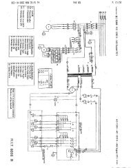
<strong>IBS</strong> <strong>2000</strong> Wiring DiagramsDirect Drive36 • Service Manual — COATS Model <strong>IBS</strong> <strong>2000</strong>
Direct DriveService Manual — COATS Model <strong>IBS</strong> <strong>2000</strong> • 37
38 • Service Manual — COATS Model <strong>IBS</strong> <strong>2000</strong>Direct Drive
Direct DriveService Manual — COATS Model <strong>IBS</strong> <strong>2000</strong> • 39
9112388 12/00 rev. 1 © Copyright 1998 Hennessy Industries and COATS All Rights Reserved Printed in USA