Installation and Operating Manual 262-30T Temperature ... - Crompton
Installation and Operating Manual 262-30T Temperature ... - Crompton
Installation and Operating Manual 262-30T Temperature ... - Crompton
Create successful ePaper yourself
Turn your PDF publications into a flip-book with our unique Google optimized e-Paper software.
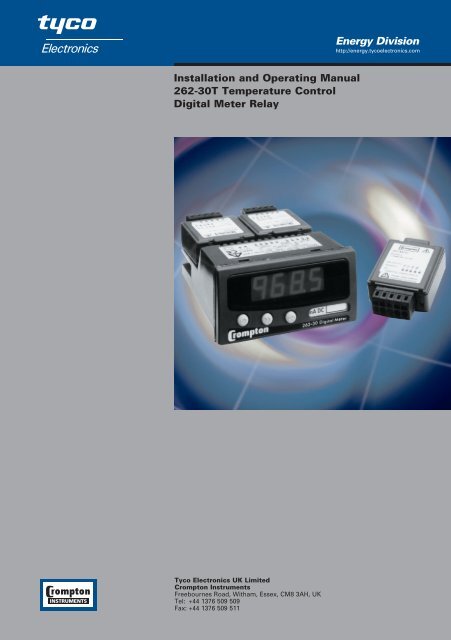
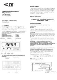
1.0 GeneralThe unit is a highly accurate <strong>and</strong> stable digital temperature indicator that accepts all commonlyused temperature sensors. The unit can be used "st<strong>and</strong> alone" or, with the Modbus serialcommunications module option, as part of a larger system.The case design enables option Modules to be easily installed without the need for dismantlingor re-calibration. A range of Modules are available for:●Relay outputs <strong>262</strong>-RLY●Isolated Analogue Output <strong>262</strong>-ALG●Modbus serial communication <strong>262</strong>-MOD1
1.0 General continuedThe diagram shows the rear panel positions for all electrical connections.2.0 UnpackingPlease inspect the instrument carefully for any signs of shipping damage. The packaging hasbeen designed to afford maximum protection, however, we cannot guarantee that mish<strong>and</strong>lingwill not have damaged the instrument. In the case of this unlikely event, please contact yoursupplier immediately <strong>and</strong> retain the packaging for subsequent inspection.2
3.4 Power Supply ContinuedWires are retained by screws. Ensure that the exposed section of the wire is fully inserted <strong>and</strong>that no loose str<strong>and</strong>s are exposed.3.5 Sensor ConnectionsAll sensor connections are made via a five way "fast wiring" socket at the rear of the unit (wiresize 0.5 to 1.5mm 2 ).Insert small screwdriver blade into tension clamp orifice, (1) push <strong>and</strong> twist to deflect clamp intoopen position. Do not lever screwdriver thus forcing connector body sideways. Insert conductortail sufficiently into (2) then release screwdriver. Ensure no loose wire str<strong>and</strong>s protrude.5
4.3 Entering Menu ModeThe Root Menu mode is accessed from "Run" by pressing ENTER (B&C) followed by CYCLE (A).The display will now show "inPt". In order to underst<strong>and</strong> what this means, the followingdiagram shows where we are within the basic Root menu.* Slot menus only appear when respective option modules are fitted.4.3.1 Moving Around The MenuOne can browse through the Root menu by pressing CYCLE (A) which moves the menu positionfrom left to right (after reaching SYS, the menu position wraps around to the start).4.3.2 Entering A SubmenuTo enter a submenu, first cycle around the Root menu until the required submenu is displayed.For the purposes of this tutorial press the CYCLE (A) key until InPt is displayed. Pressing SHIFT(B) enters the Input Submenu.TYPe will now be displayed. The diagram shows our position in relation to other items in themenu.Pressing CYCLE (A) moves left to right, wrapping around at the end. The unit alters items in themenu list depending upon settings made.7
4.3.2 Entering A Submenu continued4.3.3 Editing A ParameterThe items displayed in the menu can either be submenus, parameters or numbers, most of theitems in the Inputs menu are parameters which can be edited.Press the CYCLE (A) key until tYPe is displayed, then press SHIFT (B).The current setting will now be shown flashing. This item is changed by pressing the INC (C)key.The choice of options available is as follows:Press the INC (C) key until "rtd" is displayed.8
4.3.3 Editing A Parameter continuedNote that whilst the display is flashing, the option on the display has not been saved to memory.To select an option, the ENTER key sequence is used. Press ENTER (B&C). The display will stopflashing momentarily before returning to Menu mode. The system automatically steps on to thenext entry to speed the process of programming. This method of editing parameters is repeatedthroughout the menu structure.4.3.4 Returning From SubmenusTo return up from the inPt menu to the root menu wait for 1 minute or press the ESCAPE (A&B)key. Pressing the ESCAPE key from our current position in the Inputs submenu takes us back tothe Root menu. The menu position will automatically step to the next menu item, if no modulesare fitted the unit will show SYS, if modules are fitted SLt1 or SLt2 will be shown.The Root menu, as its name suggests is not a submenu. Pressing the ESCAPE (A&B) keysequence whilst in the Root menu will take the user out of Menu mode <strong>and</strong> into Run mode.Thus the process variable will be shown on the display. Refer to section 5.2 if an error code isshown after programming in menu mode.4.4 The Menus4.4.1 The INPt (INPUT) SubmenuThe INPt submenu is used to program all the characteristics of the input sensor <strong>and</strong> any signalconditioning that may be required. The selection of an option in the list may affect items furtherdown. Therefore, during programming, the user should start at the top of the menu <strong>and</strong> workdown, to avoid setting an option which may later become obsolete. Short menu items shown inbold.TITLE OPTIONS DETAILtYPE rtd, tc Defines sensor type connecteddP 888.8, 88.88, 8888 Defines decimal point locationLin cA, J, t, r, S, E, F, n, cuSt Shown only with TC sensorLin Euro, din, JiSc, cuSt Shown only with RTD sensorunit dEg c, dEg F Defines engineering rangebout Hi, Lo Defines high or low scale burnoutFiLt AdPt, nonE, 2 sec, 10 sec Input filtering or smoothing9
4.4.2 The SyS (System) SubmenuTITLE OPTIONS DETAILLiSt FuLL, SHrt Selects full or short menucLEn oFF, on Clear enable (option modules)SPEn oFF, on Setpoint enable (option modules)PASS 4 digit passcode Modify any password codeoFFS User defined offset Take care when replacing sensorRefer to section 7.0 for SLt menu structures.5.0 Operation5.1 Run Mode OperationThe normal display shown in this mode is the process variable.KEYPRESS ACTIONCYCLE (A) View setpoints (Adjust value if SPEn enabled)CLEAR (A&C) Clear latched alarms (cLEn enabled)5.2 Failure ModesIf the instrument detects an input, configuration or system error the effect upon the display <strong>and</strong>any output options fitted will be determined by the burnout setting in the input menu. These aresummarised below.Burnout Display Alarms ReturnUpscale All on 22mADownscale All off OmA10
6.0 Specification @20 °C6.1.1 RTD (Pt-100)Sensor Range-200 to +850°C [18 to 390 ohm]Linearisation St<strong>and</strong>ard Euro BS EN 60751 (IEC-751)DIN BS 1904 (DIN43760)USA JISC 1604Custom CUSTOM [X] See note 2Measurement Accuracy0.1°C ±0.05% RdgThermal Drift Zero 0.008 °C/°CSpan100 ppm /°CExcitation Current 300µA to 550 µAMaximum Lead Resistance50 ohms per leg (balanced)Lead Resistance Effect0.002 °C/ ohm6.1.2 Thermocouple InputsSensor Ranges Thermocouple MeasuringType Range °C See note 3TC Type K (cA) -200 to 1370TC Type J (J) -200 to 1200TC Type T (t) -210 to 400TC Type R (r) -10 to 1760TC Type S (S) -10 to 1760TC Type E (E) -200 to 1000TC Type F/L (F) -100 to 600TC Type N (n) -180 to 1300CUSTOM (cust) -999 to 9999Linearisation St<strong>and</strong>ard BS EN 60584-1 (IEC 584-1)CustomCUSTMeasurement Accuracy±0.04% FRI ±0.04% Rdg or 0.5°C(Which ever is greater)FRI = Full Range InputThermal Drift Zero 0.1 µV/°CSpan100 ppm/°CCold Junction Error±0.5°CCold Junction Tracking0.05°C/°CCold Junction Range-30 to +60°C11
6.1.2 Thermocouple Inputs continuedNotes:1. Measurement Accuracy includes the effect of calibration, linearisation <strong>and</strong> repeatability.2. Customer linearisation requirements are available preprogrammed at the factory, contactyour supplier for details.3. Consult thermocouple reference st<strong>and</strong>ards for thermocouple material limitation.6.2 General Specification @ 20 °CInput/Output Isolation500VAC rms (galvanically isolated)Update time250 mS maximumTime Constant (Filter off)
7.0 Option Modules7.0.1 Installing ModulesPower must be removed from unit before adding/removing a module.Slot 1 (alarm 1 <strong>and</strong> 2) should be positioned on the left side of the unit looking from the front tocorrespond to front panel alarm indicator, slot 2 (alarm 3 <strong>and</strong> 4) is positioned on the right.7.1 <strong>262</strong>-RLY Dual Relay ModuleThe relay module has two "change over" relays with a common wiper.7.1.1 SLT1, SLT2 (Relay Module) SubmenuEach relay can be set as high or low alarm independently.TITLE OPTIONS DETAILAL1 Hi, Lo Alarm actionSEt1 User defined PV at which the alarm triggersHYS1 User defined Hysterisis b<strong>and</strong> (see below)LAt1 oFF, on Sets latching to on or offinUI oFF, on Invert relay operationContinues through for Relays 2 - 4 (when fitted).Short menu items shown in bold.13
7.1.1 SLT1, SLT2 (Relay Module) Submenu continuedHysteresis Operation7.1.2 Relay SpecificationACDCMaximum Load 7A @ 250V 7A @ 30VMaximum Power 1750VA 210WMaximum Switching 250V 125VElectrical Life 10 5 operations at rated loadMechanical Life 50 Million operations7.2 <strong>262</strong>-ALG, Isolated Analogue Output ModuleThe re-transmission module (when fitted) is designed to provide 0-10mA, 0-20mA or 4-20mAoutput in active or passive modes. The output can be any portion of the display. The module canbe used in two modes:Note: Only one analogue output module can be fitted.14
8.0 Mechanical DetailMaterialWeightFlammabilityModule weightPanel cutoutABS/PC200gIEC707 FV040g typical92mm x 45mm15
The Information contained in these installation instructions is for use only by installers trained to make electrical power installations <strong>and</strong> is intendedto describe the correct method of installation for this product. However, Tyco Electronics has no control over the field conditions which influenceproduct installation.It is the user's responsibility to determine the suitability of the installation method in the user's field conditions. Tyco Electronics' only obligationsare those in Tyco Electronics' st<strong>and</strong>ard Conditions of Sale for this product <strong>and</strong> in no case will Tyco Electronics be liable for any other incidental,indirect or consequential damages arising from the use or misuse of the products. <strong>Crompton</strong> is a trade mark.Tyco Electronics UK Limited<strong>Crompton</strong> InstrumentsFreebournes Road, Witham, Essex, CM8 3AH, UKTel: +44 1376 509 509 Fax: +44 1376 509 511http://energy.tycoelectronics.com


