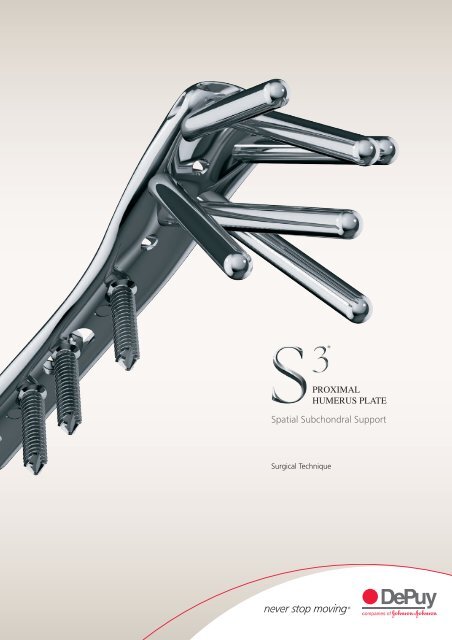
S3® Proximal Humerus Plate Spatial Subchondral Support ... - Biomet
S3® Proximal Humerus Plate Spatial Subchondral Support ... - Biomet
S3® Proximal Humerus Plate Spatial Subchondral Support ... - Biomet

You also want an ePaper? Increase the reach of your titles
YUMPU automatically turns print PDFs into web optimized ePapers that Google loves.
®PROXIMALHUMERUS PLATE<strong>Spatial</strong> <strong>Subchondral</strong> <strong>Support</strong>Surgical Technique
ContentsIntroduction 3S 3® <strong>Proximal</strong> Humeral <strong>Plate</strong> 4Deltopectoral Approach 6Surgical Technique 9Ordering Information 141
IntroductionIntroductionDePuy’s experience in developing best in class implants for fracture fixationthrough locked plating technology has been used to design the S 3 plate forthe management of proximal humerus fractures. The S 3 takes full advantageof the principle of spatial subchondral support successfully applied in thedesign of its sister product, the DVR ® distal volar radius plate.The S 3 system is designed around the natural anatomy of the proximalhumerus to address varus collapse. Convergent and divergent fixed anglepegs are centred around the natural axis of the humeral dome. This distinctconcept in humeral fixation helps reduce the risk of varus collapse by creatingsupport for the humeral dome.The S 3 plate has been designed to help prevent subacromial impingement.The distinct design of the S 3 allows the plate to be positioned more distally,minimising the risk of impingement.The S 3 pegs and screws utilise blunt smooth ends so that fixation can beprovided directly below the hard articular shell. Engaging the subchondralbone with blunt fixation reduces the risk for articular surface penetration.Intended UseThe S 3 <strong>Proximal</strong> <strong>Humerus</strong> <strong>Plate</strong> is indicated for fractures and fracturedislocations, osteotomies, and non-unions of the proximal humerus.Surgical Approach<strong>Proximal</strong> Humeral fractures are treated with the S 3 through thedeltopectoral approach.3
S 3 <strong>Proximal</strong> <strong>Humerus</strong> <strong>Plate</strong>Minimises Subacromial Impingement• The S 3 plate is designed to be positioned approximately 2.5 - 3.0 cm distal tothe greater tuberosity helping to prevent subacromial impingement2.5 - 3.0 cmMinimises Varus CollapseProvides Strong and Secure Fixation• The design of the pegs distributes the load moreanatomically through the full range of motion bymaintaining the neck shaft angle of 135º with a retroversionangle of 30º minimising the risk of varus collapse• The proximal end of the S 3 has fixed angle locking pegs/screw holes. Its parametric design of convergent anddivergent screw trajectories ensures a consistent spatialdistribution of the pegs within the entire humeral head. Thisparticular distribution provides spatial subchondral supportto resist varus forces throughout the full range of motion• 4.0 mm blunt tipped subchondral support pegs/screwsprovide improved stability while preventing protrusionthrough the articular surface135˚• <strong>Proximal</strong> and distal locking pegs/screws provide a stronginterface for secure fixation4
Ease of UseF.A.S.T. GUIDE ® TechnologyThe S 3 plate comes pre-loaded with F.A.S.T GUIDETechnology, Fixed Angle Screw Targeting Guides,which facilitate accurate drilling and easy plateidentificationCentral K-wireCentral K-wire hole provides a guide for initialplate positioning through the use of fluoroscopyand temporary fixationSuture HolesSuture holes allow simplified tuberosity repairsafter humeral head fixation through frontal andlateral accessUser Friendly System DesignIntuitive set layout and simple instrumentationallow for convenience in surgery5
Deltopectoral approachPatient positioning and approachThe procedure can be performed in thebeachchair position or supine position (Figure 1)as per the surgeon’s discretion. If necessarya sterile Mayo stand can be used to assistduring dissection.Figure 1Assess the fracture fluoroscopicallyExamine the fracture using intraoperativefluoroscopy. Internal rotation, external rotationand sometimes axillary views are necessary(Figure 2).Figure 2Cephalic veinExposureMake an incision approximately 12–14 cm overthe coracoid process, extending down to thedeltoid insertion in an oblique fashion. Identifyand retract the cephalic vein (Figure 3).Figure 36
Identify the Biceps TendonGently retract the coracobrachialis medially.Find the pectoralis insertion at the floor of thedeltoid pectoralis interval. If necessary release theproximal third of the pectoralis tendon to exposethe biceps (Figure 4).<strong>Proximal</strong> release ofpectoralis tendonFigure 4Complete ExposureDevelop the subacromial space and mobilise theproximal deltoid (Figure 5).Note: Use of a large, blunt humeral headdepressor can facilitate exposure.Figure 5Fracture Debridement and ReductionReduce the humeral head fragments and checkthe reduction under fluoroscopy (Figure 6).Note: In the case of severe comminution,suturing the rotator cuff together will helpreduce the tuberosities. To facilitate healing,bone graft should be considered.Figure 67
Surgical Technique<strong>Plate</strong> PositioningSelect the appropriate side plate (lime=left;rose=right) and length (3,4,6,8,11 or 14 hole)(Figure 7).LeftRightFigure 7Position the plate 2.5–3.0 cm distal to the greatertuberosity. The anterior border of the plate(straight border) should be immediately lateral tothe bicepital groove (Figure 8).Figure 8Drill Central K-WireDrill the 2.0 mm K-wire (Cat No KW20SS) throughthe central K-wire hole on the proximal portion ofthe plate aiming the centre of the humeral head(Figure 9).Figure 98
Verify Central K-WireCheck the trajectory of the central K-wire underfluoroscopy. If there is a deviation from the centreof the humeral head remove the K-wire and redrilluntil the centre is reached (Figure 10).Note: Other K-wire holes can be used toprovisionally fix the plate to the bone.135˚Figure 10Distal <strong>Plate</strong> Provisional FixationSecure the plate to the humeral shaft usinga 3.8 mm Multidirectional Cortical Screw(Cat No MDXX ) to allow for later plateadjustments (Figure 11).Drill with the 2.8 mm Drill Bit (Cat No DB28)through the oblong hole of the plate shaft, usingthe Soft Tissue Protector (Cat No SSTG).Figure 11Determine the required screw size using the DepthGauge (Cat No SBDG). (Figure 12)Figure 129
Surgical TechniqueFix the plate into place with a 3.8mmMultidirectional Cortical Screw (Cat No MDXX)using the Hex Driver (Cat No FHDS) (Figure 13).Figure 13Drill Stop<strong>Proximal</strong> <strong>Plate</strong> FixationDrill through the inferior anterior F.A.S.T. GUIDEwith the 4.0mm Short Drill Bit (Cat No FDB40S),and perforate the cortex. The drill bit has a stopthat will only allow it to penetrate the near cortex(Figure 14).Note: The K-wire can be bent to avoid drillbit obstruction.Figure 14Manual Drill for <strong>Subchondral</strong> <strong>Support</strong> PegsTo prevent the powered drill penetratingthrough the rear cortex the following stepshould only be made by manual drilling.With the 4.0 mm Long Drill Bit (Cat No FDB40Lor FDS40) attached to the Driver Handle (Cat NoQCH), advance through the proximal plate holeF.A.S.T. GUIDE until resistance from subchondralbone is felt. This will ensure the peg engagessubchondral bone for optimal fixation (Figure 15).Figure 15Note: Do not use powered drilling forinserting the subchondral pegs. When manualdrilling for smooth pegs use Cat No FDB40L.When manual drilling for partially threadedpegs use Cat No FDS40.10
Determine Peg LengthOnce resistance is felt, fluoroscopy imagingshould verify that the tip of the manual drill isclose to the subchondral bone. Care should betaken not to penetrate the subchondral bone. Usethe appropriate side of the dual scale drill bit todetermine the correct peg size (Figure 16).Note: The Long Depth Gauge has a biasbuilt in that will reduce the observed depthby 2.5 mm. If subchondral bone contact isdesired, add 2.5 mm to the Depth Gauge.Note: If a F.A.S.T. GUIDE was removed beforethe screw length was recorded, insert the4.0mm Drill Guide (Cat No DRGSH) anddetermine the screw size by using theappropriate side of the dual scale steppedDepth Gauge (Cat No FSDGS).Figure 16Peg InsertionRemove and discard the respective F.A.S.T. GUIDEand insert the appropriate size peg using theHex Driver (Cat No FHDS) (Figures 17 and 18).Prepare the remaining proximal holes in acrisscross, opposing fashion to maintain a properand stable reduction (Figure 19).Figure 17351462Figure 18Figure 1911
Surgical TechniqueAttach Tuberosities to <strong>Plate</strong>Secure the tuberosities to the plate by passing theneedles close to the insertion of the tendon andthen through to side, front or top loading wireattachment points found on the proximal end ofthe plate (Figure 20).Note: An alternate approach is to applythe sutures to the plate prior to placingthe subchondral support pegs. This may aidin reduction.Figure 20Insert Distal ScrewsUse the appropriate end of the Soft TissueProtector (Cat No SSTG) and drill to the far cortexwith the 2.8 mm Drill Bit (Cat No DB28). Decideon length using the Barrel Depth Gauge (Cat NoSBDG) (Figure 21).Figure 21Fix the remaining Shaft Cortical Screws witheither 90º Locking Screws (Cat No NLXX) orMultidirectional Screws (Cat No MDXX).Use a Set Screw (Cat No NLSS) to lock each 90ºScrew to the plate. Do not use a set screw whenusing Multidirectional Screws (Figure 22).Figure 2212
Final VerificationEvaluate the humerus under fluoroscopy toassess the reduction and to confirm properplate positioning (Figures 23 and 24).Figure 23Figure 2413
Ordering InformationPegs and ScrewsSmooth Peg, LockingProvide spatial subchondral support.Cat No STPXX / STPXXX20, 25 and 30–65 mm lengths (2.5 mm steps)Threaded Pegs, LockingHelp to capture and lag the humeral head.Cat No STPTXX / STPTXXX20, 25 and 30–65 mm lengths (2.5 mm steps)90˚ Cortical Screws, Non-lockingProvide bi-cortical fixation while locking to theplate using the NL-SS set screws.Cat No NLXX20 mm – 38 mm lengths (2.0 mm steps)Multi-directional Cortical Screws,Non-LockingProvide multi-directional fixation when usedthrough the oblong hole.Cat No MDXX20 mm – 38 mm lengths (2.0 mm steps)90° Locking Set ScrewSecures the 90° cortical screws to the plate.Cat No NLSSS 3 <strong>Proximal</strong> <strong>Humerus</strong> <strong>Plate</strong> OptionsLime=Left; Red=RightS 3 <strong>Plate</strong>, 3 Holes:16 mm x 71 mmSSPL3 / SSPR3S 3 <strong>Plate</strong>, 4 Holes:16 mm x 84 mmSSPL4 / SSPR4S 3 <strong>Plate</strong>, 6 Holes:16 mm x 109 mmSSPL6 / SSPR6S 3 <strong>Plate</strong>, 8 Holes:16 mm x 150 mmSSPL8 / SSPR8S 3 <strong>Plate</strong>, 11 Holes:16 mm x 190 mmSSPL11 / SSPR11S 3 <strong>Plate</strong>, 14 Holes:16 mm x 236 mmSSPL14 / SSPR14The S 3 plate, pegs and screws are manufactured from 316L Stainless Steel14
S 3 <strong>Proximal</strong> <strong>Humerus</strong> <strong>Plate</strong> Modular TrayTop Tray1 SSTG Soft Tissue Guide2 DB28 Drill Bit 2.8 mm3 SBDG Depth Gauge4 FHDS Hex Driver510125 FDB40S Drill Bit 4.0 mm Short6 DRGSH Drill Guide 4.0 mm7 FDS40 Drill Bit 4.0 mm Step3448138 QCH Quick Connect Handle1 2799 FDB40L Drill Bit Fast 4.0 mm Long10 SDI Square Driver Insert 2.0Mm11 FSDGS Depth Gauge Step Shoulder Fast6111212 MQC Mini Quick Connect Handle13 KW20SS K-wire 2.0 mm SSBottom Tray14 SSPL14 14 Hole <strong>Plate</strong>, Left15 SSPL11 11 Hole <strong>Plate</strong>, Left16 SSPL04 4 Hole <strong>Plate</strong>, LeftSSPL03 3 Hole <strong>Plate</strong>, Left17 SSPL06 6 Hole <strong>Plate</strong>, Left1618141520 2118 SSPR04 4 Hole <strong>Plate</strong>, RightSSPR03 3 Hole <strong>Plate</strong>, Right19 SSPR06 6 Hole <strong>Plate</strong>, Right20 SSPR11 11 Hole <strong>Plate</strong>, Right21 SSPR14 14 Hole <strong>Plate</strong>, Right17 1915
This publication is not intended for distribution in the USA.DePuy Orthopaedics EMEA is a trading division of DePuy International Limited.Registered Office: St. Anthony’s Road, Leeds LS11 8DT, EnglandRegistered in England No. 3319712DePuy Orthopaedics, Inc.700 Orthopaedic DriveWarsaw, IN 46581-0988USATel: +1 (800) 366 8143Fax: +1 (574) 267 7196www.depuy.comDePuy International LtdSt Anthony’s RoadLeeds LS11 8DTEnglandTel: +44 (0)113 387 7800Fax: +44 (0)113 387 78900086©DePuy International Ltd. and DePuy Orthopaedics, Inc. 2011.All rights reserved.0612-29-00 version 3 Issued: 08/11