You also want an ePaper? Increase the reach of your titles
YUMPU automatically turns print PDFs into web optimized ePapers that Google loves.
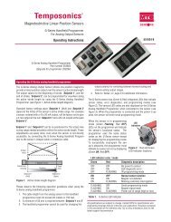
Temposonics ®Magnetostrictive, Absolute, Non-contactLinear-Position <strong>Sensors</strong>E-<strong>Series</strong> Model <strong>EH</strong><strong>CAN</strong>open OutputData SheetSENSORSDocument Part Number:551313 Revision B®Model <strong>EH</strong> rod-style position sensorStroke Length: 50 mm to 2500 mm (or 2 in. to 100 in.)FEATURES• Linear, Absolute Measurement• Non-Contact Sensing Technology• Linearity Deviation Less Than 0.02% F.S.• Repeatability Within 0.005% F.S.• <strong>CAN</strong>open Interface:• Direct Position Output• Velocity Output• Single or Dual Magnet Measurements• Stroke Length Range: 50 mm to 2500 mm (or 2 in. to 100 in.)• Hermetically-Sealed Stainless Steel For IP69K IngressProtection• EMI Shielded and CE Certifi edBENEFITS• Compact Stainless Steel Position Sensor, Designed For Use InHydraulic Cylinders• Standard 10 mm dia. Sensor Rod For Typical Applications• Optional 7 mm dia. Sensor Rod For Use In Small BoreCylinders• Simultaneous Multi-position Measurements for 2 Magnets• Over Voltage Protection to 36 Vdc and Polarity Protectionup to -30 VdcAPPLICATIONS• Clevis Mounted or Space Limited Cylinder Applications• Harsh Industrial Conditions• High-Pressure Washdown• Gates and Valve ControlTYPICAL INDUSTRIES• Fluid Power• Factory Automation• Steel Mills• Material Handling and Packaging• Water ManagementTime-based Magnetostrictive position sensing principleMagnetic field encompassesentire waveguide - generatedby the interrogation pulseInterrogationReturn wireWaveguideStrain-Pulse detectorBias magnetMovable position magnetMagnetic field fromposition magnetInteraction of magneticfields causes waveguide togenerate a strain pulseBenefits of MagnetostrictionTemposonics linear-position sensors use the time-based magnetostrictiveposition sensing principle developed by <strong>MTS</strong>. Within thesensing element, a sonic-strain pulse is induced in a specially designedmagnetostrictive waveguide by the momentary interaction of twomagnetic fields. One field comes from a movable permanent magnetthat passes along the outside of the sensor. The other field comesfrom an “interrogation” current pulse applied along the waveguide.The resulting strain pulse travels at sonic speed along the waveguideand is detected at the head of the sensing element.The position of the magnet is determined with high precision andspeed by accurately measuring the elapsed time between the applicationof the interrogation pulse and the arrival of the resulting strainpulse with a high-speed counter. The elapsed time measurement isdirectly proportional to the position of the permanent magnet and isan absolute value. Therefore, the sensor's output signal correspondsto absolute position, instead of incremental, and never requiresrecalibration or re-homing after a power loss. Absolute, non-contactsensing eliminates wear, and guarantees the best durability and outputrepeatability.All specifications are subject to change. Contact <strong>MTS</strong> for specifications andengineering drawings that are critical to your application. Drawings containedin this document are for reference only. Go to http://www.mtssensors.com forthe latest product documentation and related media.
E-<strong>Series</strong> Model <strong>EH</strong> Sensor, <strong>CAN</strong>open OutputProduct Overview/SpecificationsProduct overview<strong>MTS</strong> <strong>Sensors</strong> continues to establish new performance standards for low-cost, fully-industrial, durable position sensors using the widely preferredmagnetostrictive technology. This principle for accurate and non-contact measurement of linear-position sensing was developed 30years ago by <strong>MTS</strong> and is used with outstanding success in a large variety of industrial applications. The Temposonics model <strong>EH</strong> sensor providesas much performance as you need for your application - you benefit from the advantages of magnetostrictive position measurement at optimumcosts.The Temposonics® Model <strong>EH</strong> sensor features a pressure resistant sensor rod for direct stroke measurement inside hydraulic cylinders. Withits minimized sensor head and either a 7 mm or 10 mm rod, it is the ideal solution when space is critical. For long strokes, the model <strong>EH</strong> isavailable with measuring ranges up to 2500 mm (or 100 in.).The model <strong>EH</strong> sensor offers completely sealed stainless-steel housing for long life position measurement for rugged environments. Wheninstalled with the appropriate mating connector and cable, it features protection up to IP69K and is suitable for high-pressure washdownapplications.Product specificationsParametersOUTPUTMeasured outputvariables:Resolution:Update times:Linearity deviation:Repeatability:Outputs:SpecificationsPosition, Velocity for single or dualmagnetsPosition: 10 μm, 20 μmVelocity: 1mm/s1.0 ms up to 2400 mm< ± 0.02% full stroke(minimum ± 60 μm)< ± 0.005% full stroke(minimum ± 10 μm)Interface:<strong>CAN</strong>-Fieldbus System according toISO-DIS 11898Data protocol:<strong>CAN</strong>open Encoder Profile DS 406 V3.1CiA Standard DS 301 v3.0Baud rate, kBit/s: 1000 800 500 250 125Cable length, m: < 25 < 50 < 100 < 250 < 500Stroke length: Range:50 mm to 2500 mm (or 2 in. to 100 in.)ELECTRONICSOperatingvoltage: +24 Vdc nominal: -15% or +20%Polarity protection: ≥ -30 VdcOver voltage protection: ≤ 36 VdcCurrent drain: 40 to 60 mA(Stroke length dependent)Dielectric withstand voltage: 500 Vdc(DC ground to machine ground)ParametersENVIRONMENTALOperatingconditions:EMC test:Shock rating:Vibration rating:SpecificationsOperating temperature:-40 °C (-40 °F) to 75 °C (167 °F)Relative humidity:90% no condensationIngress protection: IP69K(when appropriate mating connector iscorrectly fitted)Electromagnetic emission:EN 61000-6-4 (for use in industrialenvironment)Electromagnetic immunity:EN 61000-6-2. The sensor meets therequirements of the EC directives and ismarked with CE.100 g (single hit)/IEC standard EN 60068-2-2715 g/10 to 2000 Hz, IEC standardEN 60068-2-6 (resonance frequenciescausing excess of 15 g are excluded)WIRINGConnection type: 5-pin (M12) male integral connectorROD-STYLE SENSOR (MODEL <strong>EH</strong>)Electronic head: Stainless steel 1.4301 / AISI 304Sensor rod: Stainless steel 1.4301 / AISI 304Operating pressure: 7 mm Rod:300 bar static, 350 bar peak(4350 psi static , 5076 psi peak)10 mm rod:350 bar static, 450 bar peak(5076 psi static , 6526 psi peak)Typical mountingtorque:45 N-m (33 ft. - lbs.)Magnet types: Ring magnet, open-ring magnet ormagnet floatTemposonics ® Linear-Position <strong>Sensors</strong> - Product Data Sheet - E-<strong>Series</strong> Model <strong>EH</strong><strong>CAN</strong>open Output, Document Part No.: 551313 Revision B 02/13, 04/13 (US)2<strong>MTS</strong> <strong>Sensors</strong>
E-<strong>Series</strong> Model <strong>EH</strong> Sensor, <strong>CAN</strong>open OutputCommunication and Functionality<strong>CAN</strong>open communication and functionalityTemposonics linear-position sensors fulfill all requirements of <strong>CAN</strong>bus (ISO 11898). The sensor’s electronics convert the position measurementsinto bus oriented outputs and transfer this data directly to the controller. The <strong>CAN</strong>bus interface is appropriate for serial data transferup to 1 Mbps maximum. Sensor integrated software supports bus profile <strong>CAN</strong>open. This communication protocol allows for a comprehensivecustomized configuration of the sensor-bus system.TEMPOSONICS E-SERIES SENSORS WITH <strong>CAN</strong>open INTERFACEE-<strong>Series</strong> sensors with <strong>CAN</strong>open protocol are based as bus-nodes onthe OSI reference model and are available with application data forsingle or dual-magnet measurements:Application data:• Position measurement• Velocity measurement• Setpoints• Status<strong>CAN</strong>open corresponds to encoder profile ‘DS-406 V3.1 (CiA Draftstandard DS-301 V3.0)’. The <strong>CAN</strong>open functionality is describedbelow in the following communication objects.<strong>CAN</strong>open CONFIGURATION TOOLThe EDS (Electronic Data Sheet) download is available atwww.mtssensors.com for configuration.SERVICE DATA OBJECT (SD0)The SDO is mainly used for sensor configuration. SDO messages areused for read and write access to all entries in the object directory.Selectable parameters are as follows:• Operational range setup for magnets 1 and 2• Zero adjustmet preset for magnets 1 and 2• 4 set points for each magnetPROCESS DATA OBJECT (PDO)The PDO provides data transfer of sensor measurements in up to8-byte data blocks. The sensor uses PDO’s to relay parameters foreach magnet in one or two PDO’sData formats:• Position• Velocity• Limit status• Limit status of operational rangePDO TRANSMISSION TYPES• Asynchronous (cycle time of 1 to 65.535 ms) or synchronous• Synchronization Object (SYNC) messages are sent from thecontroller to the sensor, the sensor then transmitts measurementvaluesSYNC OBJECTIs responsible for synchronized bus communicationEMERGENCY OBJECTEmergency messages are transmitted as:• Sensor signal breakdown• Communication fault<strong>MTS</strong> <strong>Sensors</strong> 3Temposonics ® Linear-Position <strong>Sensors</strong> - Product Data Sheet - E-<strong>Series</strong> Model <strong>EH</strong><strong>CAN</strong>open Output, Document Part No.: 551313 Revision B 02/13, 04/13 (US)
E-<strong>Series</strong> Model <strong>EH</strong> Sensor, <strong>CAN</strong>open OutputMeasurement Options and Dimension ReferencesDual magnet outputsMEASUREMENT OPTIONSE-<strong>Series</strong> sensors provide options for simultaneous multi-positionmeasurements by using up to two magnets per sensor.The options for single-magnet or dual-magnets is specified in thesensor model number when ordered. For single-magnet sensors thesensor’s full active stroke length is utilized by the one magnet. Forexample when using forward-acting outputs, the output is 0% of itsvalue when the magnet is at the null position (start of stroke) and100% of its value when at the edge of the dead zone (end of stroke),(see ‘Figure 1’).However, for dual-magnet sensors the sensor’s active stroke lengthmust be shared by the two magnets, and a separation > or = to 75mm (3 in.) must be maintained between the two magnets (frontside of the first magnet to front side of the second magnet). Thisminimum distance between magnets is needed to maintain propersensor output. Therefore, for the second magnet the start of stroke(0% output) is set at 75 mm away from the sensor’s null position.Likewise, for the first magnet the end of stroke (100% output) is nowset 75 mm away from the edge of the dead zone (see ‘Figure 1’).The result of using the dual-magnet E-<strong>Series</strong> options is that thestroke length available for each magnet is 75 mm less (or 3 inchesless when specifying stroke length in inches) than the sensor’s fullactive stroke length as indicated in the model number.When ordering the single-magnet E-<strong>Series</strong> sensor the minimumstroke length available is 50 mm or 2 inches. However when orderingdual magnet E-<strong>Series</strong> sensors the minimum stroke length availableis 125 mm (i.e. 50 mm minimum, plus 75 mm for the minimumdistance between magnets). Likewise, when specifying strokelength in inches the minimum stroke length available is 5 inches (i.e.2 inch minimum, plus 3 inches for the minimum distance betweenmagnets).Singlemagnet sensorTemposonics ®E-<strong>Series</strong>Temposonics ®E-<strong>Series</strong>EDualmagnet sensorE(0%)(0%)Null positionstart of strokeM1Active stroke lengthM1A≥ 75 mmor (3 in.)M1 M2 M1A M2A(0%)1 st Magnet2 nd Magnet(100%)End of strokedead zone(100%)(100%)Figure 1. Single and dual-magnet measurementsSensor dimension referencesDrawings are for reference only, contact applications engineering for tolerance specific information.The model <strong>EH</strong> sensor shown in ‘Figure 2’ can be ordered with flange styles M18 x1.5 or 3/4 -16 UNF-3A and a 7 mm or 10 mm diametersensor rod. Magnets must be purchased separately; refer to ‘Standard magnet Selections (Model <strong>EH</strong>)’ for standard magnet orderinginformation.MODEL <strong>EH</strong>Null position, Start of StrokeSpan position, End of Stroke13 mm(0.5 in.)48 mm(1.9 in.)51 mm(2 in.)Stroke Length50 mm to 2500 mm (or 2 in. to 100 in.)63.5 mm (2.5 in.)Dead zone34 mm(1.3 in.)34 mm(1.3 in.) dia.5-pin8 mm(0.3 in.)14 mm(0.6 in.)Threaded flangeM18 x 1.5 or3/4-16 UNF-3ASensor rod7 mm (0.27 in.) dia. or10 mm (0.39 in.) dia.Refer to the model <strong>EH</strong> sensor ordering information forrod housing and flange typesFigure 2.E-<strong>Series</strong> model <strong>EH</strong> sensor dimension referenceTemposonics ® Linear-Position <strong>Sensors</strong> - Product Data Sheet - E-<strong>Series</strong> Model <strong>EH</strong><strong>CAN</strong>open Output, Document Part No.: 551313 Revision B 02/13, 04/13 (US)4<strong>MTS</strong> <strong>Sensors</strong>
Standard magnet options (Model <strong>EH</strong>)E-<strong>Series</strong> Model <strong>EH</strong> Sensor, <strong>CAN</strong>open OutputStandard Magnet SelectionsMagnets must be ordered separately with Model RH position sensors. The standard ring magnet (part number 201542-2) is suitable for mostapplications.POSITION MAGNET SELECTIONS (Magnet must be ordered separately) (Drawing dimensions are for reference only)Magnet and magnet dimensions Description Part number14 mm(0.55 in.)MAGNET FLOAT SELECTION (Drawing dimensions are for reference only)60°4 HolesEach 4.3 mm (0.17 in.) dia.90° apart on24 mm (0.94 in.) dia.4 HolesEach 4.3 mm (0.17 in.) dia.90° apart on24 mm (0.94 in.) dia.21 mm(0.81 in.)2 HolesEach 4.3 mm(0.17 in.) dia. on24 mm (0.94 in.) dia.25 mm(0.97 in.)Standard ring magnetI.D.: 13.5 mm (0.53 in.)O.D.: 33 mm (1.3 in.)Thickness: 8 mm (0.3 in.)Operating temperature:- 40 °C to 100 °CMagnet spacer(Non-ferrous, use with ring magnetPart number: 201542-2)I.D.: 14 mm (0.56 in.)O.D.: 32 mm (1.25 in.)Thickness: 3.2 mm (0.125 in.)Ring magnetI.D.: 13.5 mm (0.53 in.)O.D.: 25.4 mm (1 in.)Thickness: 8 mm (0.3 in.)Operating temperature:- 40 °C to 100 °COpen-ring magnet, Style MI.D.: 13.5 mm (0.53 in.)O.D.: 33 mm (1.3 in.)Thickness: 8 mm (0.3 in.)Operating temperature:- 40 °C to 100 °CThis magnet may influence the sensor performancespecifications for some applications.201542-2400633400533251416-214 mm (0.55 in.) Min. I.D.53 mm(2.1 in.)C L51 mm (2 in.)Spherical O.D.3.4 mm (0.13 in.)Magnet float(Level sensing applications)Specific gravity: 0.70 maximumPressure: 870 psi maximum(This float is used with Model RH rod-stylesensors for hydraulic fluid or fresh waterapplications only). Collar (part no.: 560777)is recommended for end of stroke stops.2514478 mm(0.31 in.)4 mm(0.16 in.)27 mm(1.06 in.) O.D. 10 mm(0.4 in.) I.D.5 mm(0.2 in.)CollarProvides end of stroke stops for magnet float(part no.: 251447)5607778-32 threads9 mm (0.34 in.)<strong>MTS</strong> <strong>Sensors</strong> 5Temposonics ® Linear-Position <strong>Sensors</strong> - Product Data Sheet - E-<strong>Series</strong> Model <strong>EH</strong><strong>CAN</strong>open Output, Document Part No.: 551313 Revision B 02/13, 04/13 (US)
E-<strong>Series</strong> Model <strong>EH</strong> Sensor, <strong>CAN</strong>open OutputOrdering InformationE H D 3 4 1 C 0 4 1 Z1 2 3 4 5 6 7 8 9 10 11 12 13 14 15 16 17 18 19 20 21 22(Use the order matrix above to configure your Model <strong>EH</strong> sensor order number)SENSOR MODEL = E H 1 - 2<strong>EH</strong> = E-<strong>Series</strong> model <strong>EH</strong> rod-style sensor (Magnet(s) must be ordered separately)HOUSING STYLE = 3K = Flange M18 x 1.5 / Rod 7 mm dia.M = Flange M18 x 1.5 / Rod 10 mm dia.L = Flange 3/4 in. UNF / Rod 7 mm dia.S = Flange 3/4 in. UNF / Rod 10 mm dia.STROKE LENGTH = 4 - 8— — — —— — — . —M =Millimeters (Encode in 5, 10, 25 or 50 mm increments) as indicated in ‘Stroke length notes’ below.U = Inches (Encode in 0.2, 0.5, 1 or 2 in. increments) as indicated in ‘Stroke length notes’ below.Stroke Length Notes:Stroke length ranges:M = 50 mm to 2500 mmU = 2 in. to 100 in.The increment size between standard stroke lengths vary as shown below:Stroke length (mm)Ordering increment≤ 500 mm5 mm> 500 mm and ≤ 750 mm 10 mm> 750 mm and ≤ 1000 mm 25 mm> 1000 mm and ≤ 2500 mm 50 mmStroke length (IN)Ordering increment≤ 20 in.0.2 in.> 20 mm and ≤ 30 mm 0.5 in.> 30 mm and ≤ 40 mm 1 in.> 40 in. and ≤ 100 in. 2 in.SENSOR CONNECTION TYPES = D 3 4 9 - 11D34= 5-Pin (M12), male, (<strong>CAN</strong>open output)INPUT VOLTAGE = 1 121 = + 24 Vdc (+20%, -15%), standardOUTPUT = C 0 4 1 13-19C _ _ _ _ _ _ = <strong>CAN</strong>open output - Enter the 6-digit output code (1-6) defined by the selections below:[1] [2] [3] [4] [5] {6}[1] [2] [3] Protocol [4] Baud rate [5] Resolution [6] type304 = <strong>CAN</strong>open 1 = 1000 kBit/s 4 = 10 μm 1 = Standard1 or 2 magnets 2 = 500 kBit/s 5 = 20 μm404 = <strong>CAN</strong>open 3 = 250 kBit/s1 or 2 magnets 4 = 125 kBit/swith integrated busterminator resistor(120 Ohms)NUMBER OF MAGNETS (20-22) FOR MULTI-POSITION MEASUREMENT ONLY = Z 20-22Z + Enter a 2-digit codeZ _ _ = Enter 02 for 2 magnetsTemposonics ® Linear-Position <strong>Sensors</strong> - Product Data Sheet - E-<strong>Series</strong> Model <strong>EH</strong><strong>CAN</strong>open Output, Document Part No.: 551313 Revision B 02/13, 04/13 (US)8<strong>MTS</strong> <strong>Sensors</strong>
Document Part Number: 551313, Revision B 02/13, 04/13 (US)<strong>MTS</strong> and Temposonics are registered trademarks of <strong>MTS</strong> Systems Corporation.All other trademarks are the property of their respective owners.Printed in USA. Copyright © 2013 <strong>MTS</strong> Systems Corporation. All Rights Reserved in all media.®<strong>MTS</strong> Systems Corporation<strong>Sensors</strong> Division<strong>MTS</strong> Sensor TechnologieGmbH & Co. KG<strong>MTS</strong> <strong>Sensors</strong> TechnologyCorporationSENSORS3001 Sheldon DriveCary, North Carolina27513, USATel.: +1-800-633-7609Fax: +1-919-677-2343+1-800-498-4442e-mail: sensorsinfo@mts.comhttp://www.mtssensors.comAuf dem Schüffel 9D - 58513 Lüdenscheid, GermanyTel.: +49-2351-9587-0Fax: +49-2351-56491e-mail: info@mtssensor.dehttp://www.mtssensor.de737 Aihara-cho, Machida-shiTokyo 194-0211, JapanTel.: +81-42-775-3838Fax: +81-42-775-5516e-mail: info@mtssensor.co.jphttp://www.mtssensor.co.jp