en VOGEL Model: WTS - Pumpenfabrik Ernst Vogel
en VOGEL Model: WTS - Pumpenfabrik Ernst Vogel
en VOGEL Model: WTS - Pumpenfabrik Ernst Vogel

You also want an ePaper? Increase the reach of your titles
YUMPU automatically turns print PDFs into web optimized ePapers that Google loves.
Operating instructions1. G<strong>en</strong>eral1.1 ForewordThis product complies with the safety requirem<strong>en</strong>ts of EC Machinery Directive 2006/42/EC.The staff employed on installation, operation, inspection and maint<strong>en</strong>ance must beable to prove that they know about the relevant accid<strong>en</strong>t prev<strong>en</strong>tion regulations andthat they are suitably qualified for this work. If staff do not have the relevantknowledge, they should be provided with suitable instruction.The operating safety of the pumps or units (i.e. pump plus motor) supplied is only guaranteed ifthese are used in accordance with the provisions giv<strong>en</strong> in the Confirmation of Order and/or Point 4in „Installation and Operation“.The operator is responsible for following the instructions and complying with the safetyrequirem<strong>en</strong>ts giv<strong>en</strong> in these Operating Instructions.Smooth operation of the pump or pump unit can only be achieved if installation and maint<strong>en</strong>anceare carried out carefully in accordance with the rules g<strong>en</strong>erally applied in the field of <strong>en</strong>gineeringand electrical <strong>en</strong>gineering.If not all the information can be found in these Operating Instructions, please contact us.The manufacturer takes no responsibility for the pump or pump unit if the Operating Instructionsare not followed.These Operating Instructions should be kept in a safe place for future use.If this pump or pump unit is handed on to any third party, it is ess<strong>en</strong>tial that these OperatingInstructions and the operating conditions and working limits giv<strong>en</strong> in the Confirmation of Orderare also passed on in full.These Operating Instructions do not take into account all design details and variants nor all thepossible chance occurr<strong>en</strong>ces and ev<strong>en</strong>ts which might happ<strong>en</strong> during installation, operation andmaint<strong>en</strong>ance.Alterations or changes to the machine are only permitted by agreem<strong>en</strong>t with the manufacturer.Original spare parts and accessories authorised by the manufacturer should be used for greatersafety. We bear no responsibility for the consequ<strong>en</strong>ces of using other parts.We retain all copyright in these Operating Instructions; they are int<strong>en</strong>ded only for personal use bythe owner of the pump or the pump unit. The Operating Instructions contain technical instructionsand drawings which may not, as a whole or in part, be reproduced, distributed or used in anyunauthorised way for competitive purposes or passed on to others.1.2 GuaranteeThe guarantee is giv<strong>en</strong> in accordance with our Conditions of Delivery and/or the confirmation oforder.Repair work during the guarantee period may only be carried out by us, or subject to our writt<strong>en</strong>approval. Otherwise the guarantee ceases to apply.Longer-term guarantees basically only cover correct handling and use of the specified material.The guarantee shall not cover natural wear and tear and all parts subject to wear, such asimpellers, shaft sealings, shafts, shaft sleeves, bearings, wear rings etc., or damage caused bytransport or improper handling.<strong>WTS</strong> 102/3-<strong>en</strong> 3
Operating instructionsIn order for the guarantee to apply, it is ess<strong>en</strong>tial that the pump or pump unit is used in accordancewith the operating conditions giv<strong>en</strong> on the type plate and in the Confirmation of Order. Thisapplies particularly for the <strong>en</strong>durance of the materials and smooth running of the pump and shaftsealing.If one or more aspects of the actual operating conditions are differ<strong>en</strong>t, we should be asked toconfirm in writing that the pump is suitable.1.3 Safety regulationsThese Operating Instructions contain important instructions which must be followed wh<strong>en</strong> thepump is assembled and commissioned and during operating and maint<strong>en</strong>ance. For this reason,these Operating Instructions must be read by the skilled staff responsible and/or by the operator ofthe plant before it is installed and commissioned, and they must be left perman<strong>en</strong>tly ready to handat the place where the pump or pump unit is in use. The operator must <strong>en</strong>sure that the cont<strong>en</strong>ts ofthe Operating Instructions are fully understood by the staff. The operator must confirm this bysigning the „Plant Manager List“ (see Point 10). These Operating Instructions do not refer to theG<strong>en</strong>eral Regulations on Accid<strong>en</strong>t Prev<strong>en</strong>tion or local safety and/or operating regulations. Theoperator is responsible for complying with these (if necessary by calling in additional installationstaff).The safety instructions contained in these Operating Instructions have the following special safetymarkings as specified in DIN 4844:Warning against personal accid<strong>en</strong>ts which could occur if the safety instructionsgiv<strong>en</strong> in this part of the Operating Instructions are not followed.Warning against dangerous electrical voltage.Pleas<strong>en</strong>oteWarning against possible damage to property or the <strong>en</strong>vironm<strong>en</strong>t.It is absolutely ess<strong>en</strong>tial that safety information affixed directly to the pump or pump unit isfollowed and maintained so that it is always easily legible.1.4 Safety instructionsDangers of not following safety instructionsFailure to follow the safety instructions can result in the following, for example:• People being at risk because of electrical, mechanical and chemical factors.• Important functions of the pump or pump unit failing.• Dangers to the <strong>en</strong>vironm<strong>en</strong>t as a result of dangerous substances leaking out.<strong>WTS</strong> 102/3-<strong>en</strong> 4
Operating instructionsSafety instructions for the operator• Dep<strong>en</strong>ding on the operating conditions, wear and tear, corrosion or age will limit the workinglife of the pump/pump unit, and its specified characteristics. The operator must <strong>en</strong>sure thatregular inspection and maint<strong>en</strong>ance are carried out so that all parts are replaced in good timewhich would otherwise <strong>en</strong>danger the safe operation of the system. If abnormal operation or anydamage are observed, the pump must cease operation immediately.• If the breakdown or failure of any system or unit could lead to people being hurt or propertybeing damaged, such system or unit must be provided with alarm devices and/or spare modules,and they should be tested regularly to <strong>en</strong>sure that they function properly.• If there is any risk of injury from hot or cold machine parts, these parts must be protected againstcontact by the user, or suitable warning signs must be affixed.• Contact protection on moving parts (e.g. coupling guards) must not be removed from systemsthat are in operation.• If dangerous media (e.g. explosive, toxic, hot) leak out (e.g. from shaft seals), these must bedirected away so that there is no danger to people or the <strong>en</strong>vironm<strong>en</strong>t. The provisions of the lawmust be observed.• Measures should be tak<strong>en</strong> to exclude any danger from electricity (e.g. by complying with thelocal regulations on electrical equipm<strong>en</strong>t). If work is carried out on live electrical compon<strong>en</strong>ts,they should be unplugged from the mains or the main switch turned off and fuse unscrewed. Amotor protection switch is to be provided.• Basically, all work on the pump or pump unit should only be carried out wh<strong>en</strong> the pump isstationary and not under pressure. All parts must be allowed to return to ambi<strong>en</strong>t temperature.Make sure that no-one can start the motor during such work. It is ess<strong>en</strong>tial that the procedure forstopping the system described in the Operating Instructions is observed. Pumps or pump systemsthat carry media that are dangerous to health must be decontaminated before being tak<strong>en</strong> apart.Safety Data Sheets for the various liquids handled. Immediately the work has be<strong>en</strong> completed,all safety and protective devices must be replaced or restarted.• Under EC Machinery Directives, every machine must be fitted with one or more emerg<strong>en</strong>cycommand devices by which situations which repres<strong>en</strong>t an immediate danger or which could laterbe dangerous can be avoided. This does not include machines in which the emerg<strong>en</strong>cy switchescannot reduce the danger, either because they do not reduce the time required to stop themachine or because the do not allow the measures required by the danger to be tak<strong>en</strong>. Thisemerg<strong>en</strong>cy switch must:have controls that are clearly marked, easy to see and within easy reach;stop the dangerous movem<strong>en</strong>t as quickly as possible without causing any additional danger;trigger any specified safety movem<strong>en</strong>ts or allow these to be started up.If the emerg<strong>en</strong>cy command device is no longer operated after an emerg<strong>en</strong>cy „off“ switch hasbe<strong>en</strong> triggered, this must be maintained by blocking the emerg<strong>en</strong>cy command device until it isreleased again. It should not be possible to block the device without this triggering an emerg<strong>en</strong>cy„off“ switch. It should only be possible to release the device through an appropriate action; thisrelease should not start the machine up again - it should only make it possible to start it up again.• If the power supply is interrupted or restored after being interrupted or if it is changed in anyother way, this should not cause any danger (e.g. pressure surges).<strong>WTS</strong> 102/3-<strong>en</strong> 5
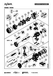
Operating instructionsSpeed, Pressure, TemperatureSuitable safety measures must be tak<strong>en</strong> at the plant to <strong>en</strong>sure that the speed, pressure andtemperature of the pump do not exceed the limit values giv<strong>en</strong>. In addition, the pump must beprotected against pressure surges such as can be caused by switching off the plant quickly (e.g. bynon-return valve on the pressure side, flywheel, air vessel).Protection against running dry<strong>WTS</strong>-Pumps in Industrial design with mediumly lubricated slide bearings may not run dry underany circumstances as this could damage the bearings.If necessary provide for monitoring devices (e.g. Flow Switch for pure water lubrication) to <strong>en</strong>surea continual flow of lubricant.Back flowThere is no back stop for the pumping medium fitted in the pump itself. If flow back from thepressure line into the collecting shaft has to be avoided a suitable non-return valve or somethingsimilar should be attached to the pressure joints.2. Description2.1 <strong>Model</strong>Block-free non-chokable pump, rod design with drive above the shaft cover.DesignOp<strong>en</strong> vortex impeller therefore absolutely free flow through the pump casing. Shaft with two ormore bearings, maint<strong>en</strong>ance-free deep groove ball bearing on the drive side. Rod bearings withbronze bearing bushes and running sleeve of stainless steel. Bearing lubrication through thepumping medium (if pumping media are pure and non-abrasive) or alternatively through purewater or grease (if pumping medium is very dirty). Pressure pipe joints are drawn high by thecovering plate.Please see the App<strong>en</strong>dix for the sectional drawings and index of parts as well as a scale drawing.The pump specification shows the characteristic curve, installation l<strong>en</strong>gth, materials, lubricationtype and motor output.Example of a Type Specification:452 <strong>WTS</strong> 20 E 1104Shaft pump: <strong>Model</strong> <strong>WTS</strong>, installation depth 1,900 mm, hydraulic data according to characteristiccurve 5, industrial design with pure water lubricated sliding bearings, impeller rated diameter 20cm, standard sealing, cast iron pump compon<strong>en</strong>ts, Motor 11 kW, 4-pole (approx. 1,450 min -1 ).<strong>WTS</strong> 102/3-<strong>en</strong> 6
Operating instructionsSpecification Diagram:2 Installation depth 900 mm3 Installation depth 1400 mm4 Installation depth 1900 mm5 Installation depth 2400 mm6 Installation depth 2900 mm7 Installation depth 3400 mm124 Characteristic curves56- Standarddesign1 Industrial design, medium lubricated slide bearings2 Industrial design, pure water lubricated slide bearings3 Industrial design, grease lubricated slide bearingsW T S1 8 Code no for impeller, approx. diameter in cmESealing with radial packing ring and gease chamberN NCast ironS S BronzeV VCast steel alloyed1 1 0 Motor power in 1/10 kW4 Normal speed 1450 min-16 Normal speed 960 min-1*) not required for normal cast iron modelCharacteristic curves:Capacity [m3/h]<strong>WTS</strong> 102/3-<strong>en</strong> 7
2.2 Permissible TemperaturesOperating instructionsThe values stated in the Confirmation of Order always apply. It is not permitted to exceed or gobelow these values. If no temperature is giv<strong>en</strong> in the Confirmation of Order the maximumpermissible pumping medium temperature is 95° C.2.3 Bearings and LubricationThe roller bearing situated above the shaft takes up the axial forces and radial forces which occurnear the coupling. It is filled with grease for its life cycle and thus requires no maint<strong>en</strong>ance.Dep<strong>en</strong>ding on the installation l<strong>en</strong>gth the pump has 1 (at an installation l<strong>en</strong>gth of 1,900 mm or less)or 2 (at an installation l<strong>en</strong>gth of more than 1,900 mm) slide bearings for guiding the shaft into theshaft area.Design with Medium Lubricated Slide Bearings• The pumping medium may not contain any abrasive elem<strong>en</strong>ts.• Make sure that all slide bearings are flooded wh<strong>en</strong> the pump is switched on (at installationl<strong>en</strong>gths of more than 1,900 mm also the upper rod bearing).• Otherwise no maint<strong>en</strong>ance required.Design with Pure Water Lubricated Slide Bearings• During pump operations pure water must be fed to the slide bearings. If pumping media t<strong>en</strong>d toconglutinate or leave deposits it may be necessary to leave the pure water supply switched onev<strong>en</strong> wh<strong>en</strong> the pump is at a standstill.• On the upper surface of the base plate, a pure water connection with an R 1/4“ internal screwthread is provided for every sliding bearing.• Water consumption of approx. 1,5 litre/min at a pressure of 3 bar is to be expected per slidingbearing.Design with Grease Lubricated Slide Bearings• On the upper surface of the base plate a connection with an internal screw thread R 1/4“ isprovided. 3 to 5 grammes of grease per day are required per bearing. We recomm<strong>en</strong>d grease witha consist<strong>en</strong>cy of NLGI grade 2. Always use grease with the same base.• The lubricating pipes are delivered filled with lithium soap grease.Pleas<strong>en</strong>oteThe grease consumed <strong>en</strong>ters the pumping medium. Take care that it does not posean <strong>en</strong>vironm<strong>en</strong>tal hazard.2.4 Drive and ControlDriv<strong>en</strong> by four or six pole vertical three phase induction motors.Manual SwitchingIf no automatic control is provided the pump must be switched on and off by hand.<strong>WTS</strong> 102/3-<strong>en</strong> 8
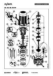
Operating instructionsAutomatic Control• Automatic Operations can be attained by fitting a mercury level switch (e.g. Type NGE) or anelectrode switch.• The switching device needed to turn the motor on and off (circuit breaker ,Y-∆-automatic circuitbreaker) must be suitable for mom<strong>en</strong>tary contact control.• An alarm switch functioning indep<strong>en</strong>d<strong>en</strong>tly of the mains can be fitted if desired.3. Transport, Handling, Storage3.1 Transport, Handling• Check the pump/pump unit immediately upon delivery/receipt of despatch for damage ormissing parts.• The pump/pump unit must be transported carefully and by compet<strong>en</strong>t personnel. Avoid seriousimpacts.• Keep the pump/pump unit in the same position in which it was supplied from the factory. Tak<strong>en</strong>ote of the instructions on the packaging.• The intake and discharge side of the pump must be closed with plugs during transport andstorage.Pleas<strong>en</strong>oteDispose of all packing materials in accordance with local regulations.• Lifting devices (e.g. fork-lift truck, crane, crane device, pulleys, sling ropes, etc.) must besuffici<strong>en</strong>tly strong. The weight of the pump/pump unit is giv<strong>en</strong> in the Data Sheet.• The unit may only be lifted by the hooks provided (on the upper side of the base plate). Thefollowing illustration shows the correct method of carrying by crane.Pleas<strong>en</strong>oteSling ropes must not be fixed to <strong>en</strong>ds of shafts or the ringloops of the motor.Do not stand underneath susp<strong>en</strong>ded loads; take note of theg<strong>en</strong>eral regulations on prev<strong>en</strong>tion of accid<strong>en</strong>ts.The pump/pump unit must be secured against tipping over andslipping until it has be<strong>en</strong> fixed in its final location.<strong>WTS</strong> 102/3-<strong>en</strong> 9
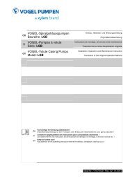
Operating instructions3.2 StoragePumps or pump units that are stored for a long time before use must be protected against moisture,vibrations and dirt (e.g. by wrapping in oil paper or plastic sheeting). Pumps must basically bestored in a place where they are protected from the weather, e.g. under cover. During this time, allsuction and discharge branches and all other intakes and outlets must be closed with dummyflanges or plugs.4. Assembly, Operation4.1 Preparing for Installation• Before installing the pump the op<strong>en</strong>ing in the shaft cover must be checked according to thedim<strong>en</strong>sions contained in the Installation Diagram (No. M 473 in the App<strong>en</strong>dix).• The seat for the base plate (Position 380 in the sectional drawing) must be horizontal.• The shaft must be at least 100 mm deeper than the installation l<strong>en</strong>gth of the pump (from theplate seat to the lower surface of the pump).4.2 Assembling and Installing the PumpPleas<strong>en</strong>oteMake sure that there is suffici<strong>en</strong>t space for service and maint<strong>en</strong>ance work to becarried out, especially for changing the drive motor or the whole pump unit.The motor v<strong>en</strong>tilator must be able to take in suffici<strong>en</strong>t cooling air.There must be at least 10 cm distance betwe<strong>en</strong> the suction grid and a wall etc.Pumps with an installation l<strong>en</strong>gth of more than 1,900 mm are delivered in two parts which mustbe fitted together as follows before being installed in the shaft.The part of the pump which has the lower rod mounted is laid on top of the shaft cover by meansof pipe support clamps over the port. After the wood<strong>en</strong> wedges and fork have be<strong>en</strong> removed theunit's drive part can be put in place.In addition, the shaft coupling 340must be slipped onto the shaft324/U, <strong>en</strong>abling the rod bearingscrews or pressure pipe screws to betight<strong>en</strong>ed. Th<strong>en</strong> raise the shaft324/U with the two screwdrivers bythe two lower bore holes of the rodpipe 305/U lying opposite eachother (see illustration), until the twoshaft screws S4 can be screwed inthe shaft groove provided throughthe two upper bore holes. Both shaftscrews must be secured with either<strong>WTS</strong> 102/3-<strong>en</strong> 10
Operating instructionsa screw locking liquid or a c<strong>en</strong>tre punch mark. Afterwards wh<strong>en</strong> the pipe support clamp has be<strong>en</strong>removed, the pump can be lowered to plate 380 and after inserting the O-ring supplied (to sealagainst smell) screwed to the foundation frame.To seal against smell place the sealing discs supplied underneath the plate screw fitting (screwhead or hexagon nut).4.3 Connecting the Pipes to the Pump• Wh<strong>en</strong> laying the pipes make sure that the pump is accessible for maint<strong>en</strong>ance and assembly.• Connect pressure line with the nominal width 100 above the plate in such a way that the pumpwill not be subject to stress during operation due to pipe torque.• If pipes are to be connected with an elastic t<strong>en</strong>sion clamp the pipes must have an externaldiameter of 108 mm.• Before connecting to the pump: Remove protective coverings from the pump supports.• Before starting operations remove coarse impurities from the pump shaft.• Wh<strong>en</strong> emptying the pipes and pump shaft make sure that the pump is suitably conserved(otherwise it can rust which will cause problems wh<strong>en</strong> operations are started).4.4 Electrical connectionThe electrical connection work may only be carried out by an authorisedprofessional. The rules and regulations valid for electrical technology, especiallythose concerned with safety measures, must be observed. The regulations of th<strong>en</strong>ational power supply companies operating in that area must also be observed.Details about electrical connections you can see in the operating instruction of the motor.4.5 Starting upThe plant may only be started up by people who are familiar with the local safetyregulations and with these Operating Instructions (especially with the safetyregulations and safety instructions giv<strong>en</strong> here).Lubricating the Slide Bearings• Pure water or grease for lubricating slide bearings must be supplied to the slide bearings beforethe pump is tak<strong>en</strong> into operation for the first time, see Point 2.3 „Storage and Lubrication“.• If the lubricant supply is switched on and off automatically with the pump, lubricant must beapplied to the slide bearings a few seconds before the pump is started.• Only switch off the pure water or grease supply after the pump has be<strong>en</strong> turned off.• If there is danger of frost insulate the lubricant pipes or protect with an additional frostprotection heating system.<strong>WTS</strong> 102/3-<strong>en</strong> 11
Operating instructionsSetting the Level SwitchGuide the cables of any level switches through the cable stuffing box of the switch cover 382/Sand and clamp according to the desired switching levels.Initial OperationsRemember that wh<strong>en</strong> starting against closed pressure line valves the power consumed by thepump is converted to heat and and discharged to the pumping medium. This can lead toimpermissible warming of the pumping medium after a relatively short time which can damagethe pump's inner fittings. Therefore after the pump has reached operating speed, the pressure sidevalve should be op<strong>en</strong>ed as quickly as possible.• Medium lubricated slide bearings must be flooded.• Start pure water or grease lubrication.• Check whether all safety devices are ready for operation.• Check the switch level setting (the lowest water level must guarantee suffici<strong>en</strong>t water coverage).• Stay away from danger area containing live parts or parts under pressure.• Check direction of rotation by switching on and off briefly. It must be the same as the directionalarrow on the bearing frame. To change the direction of rotation, see Point 4.4 „ElectricalConnection“. If the direction of rotation is correct, the flow rate will increase and running will bequieter.• Start drive device. With manual Y/∆-switching, note information in Point 4.4 „Starting“.• Οp<strong>en</strong> any slide valves pres<strong>en</strong>t in the pressure line.• Work on the pump may only be carried out wh<strong>en</strong> the curr<strong>en</strong>t has be<strong>en</strong> switched off and themovable parts are no longer turning. Switching on by unauthorized persons is to be prev<strong>en</strong>tedby appropriate measures.• In case of failure, e.g. motor does not start, fuses blow or the motor protection switch isactivated immediately, on no account should you repeat the starting procedure (danger of excesspressure in motor due to impermissible warming). Detect cause of fault and repair.After Switching On• Τhe direction of rotation can also be checked after switching on. This is done by comparing theflow rate and running noise of the pump. To change the direction of rotation, see Point 4.3. If thedirection of rotation is correct, the flow rate will increase and running will be quieter.• Check curr<strong>en</strong>t uptake and running of machine.• If faults occur, see chapter 7 „Faults - Detection and Repair“.RestartingBasically, the same procedure should be followed as for starting up for the first time. However,there is no need to check the direction of rotation of the pump unit.4.6 Operation and MonitoringBe particularly careful not to touch hot machine parts. Remember thatautomatically controlled systems may switch themselves on sudd<strong>en</strong>ly at any time.Suitable warning signs should be affixed.<strong>WTS</strong> 102/3-<strong>en</strong> 12
Operating instructionsPleas<strong>en</strong>oteRegular monitoring and maint<strong>en</strong>ance will ext<strong>en</strong>d the life of your pump or pumpsystem.• You must observe the area of application giv<strong>en</strong> in the Confirmation of Order.• Do not exceed the output giv<strong>en</strong> on the motor rating plate.• Running dry, running against a closed pressure side valve or operating in the steam phase of thepumping medium are to be avoided at all costs.• Avoid sudd<strong>en</strong> changes in temperature (temperature shocks).• The pump and the drive machine should run ev<strong>en</strong>ly and with no vibrations, check at least once aweek.• Check functioning of the lubricant supply.• Wh<strong>en</strong> operating on automatic control:Check that switching functions are working properly.if using pure water or grease lubrication leave the lubricant supply switched on during standstilltimes unless the supply is automatically switched on or off with the pump (see Point 4.5„Starting up“).• Pumps which are exposed to corrosive chemicals or to wear through abrasion must be inspectedperiodically for corrosion or wear and tear. The first inspection should be carried out after sixmonths. All further inspection intervals should be determined on the basis of the state of thepump.Permissible Number of OperationsAt a motor output up to and including 7,5 kW a maximum of 40, at higher output a maximum of20 starts per hour are permitted.4.7 Shutting down• Close slide valve in discharge pipe. This is not necessary if there is a spring-loaded non-returnvalve.• Switch of motor (make sure it runs down quietly).• Switch off the pure water or grease lubricant unless a continuous supply of lubricant is necessarydue to the nature of the pumping medium (e.g. sticky) or the pump is being operated onautomatic control.• If there is any danger of freezing, empty pump and pipes completely.4.8 DismantlingThe operator's or manufacturer's fitters should be informed as to the nature of theliquid handled. In the case of pumps handling dangerous liquids, the liquidhandled should be disposed of by <strong>en</strong>vironm<strong>en</strong>tally acceptable means before thepump is dismantled.• Before starting to disassemble the pump unit make sure that it cannot be switched on again.• Pressure line shut-off must be closed.• All compon<strong>en</strong>ts must have cooled down to ambi<strong>en</strong>t temperature.• Before dismantling the pressure line make sure that it is empty and depressurised.• Wh<strong>en</strong> the pump has be<strong>en</strong> dismantled: Secure the op<strong>en</strong>ing of the shaft.<strong>WTS</strong> 102/3-<strong>en</strong> 13
5. Maint<strong>en</strong>ance, ServicingOperating instructionsWork should only be carried out on the pump or pump unit wh<strong>en</strong> it is not inoperation. You must observe Point 1.4 „Safety instructions“.Pleas<strong>en</strong>oteMaint<strong>en</strong>ance and servicing work must only be carried out by trained, experi<strong>en</strong>cedstaff who are familiar with the cont<strong>en</strong>ts of these Operating Instructions, or by theManufacturer's own service staff. The work carried out must be duly <strong>en</strong>tered in the„Log Book“ (see Point 11) and confirmed by being signed.Storage• After 4 years r<strong>en</strong>ew the deep groove ball bearings (K) as the grease ages and loses its lubricity.• After an average of 5 years the grease in the motor bearings has aged so much that werecomm<strong>en</strong>d that you change the bearings.Cleaning the pumpDirt on the outside of the pump reduces heat discharge. Therefore the parts of the pump above thebase plate must be cleaned with water at regular intervals (dep<strong>en</strong>ding on how dirty they are).Pleas<strong>en</strong>oteThe pump should not be cleaned with pressurised water - water will get into thebearings.6. Longer periods of non-operationPleas<strong>en</strong>oteWh<strong>en</strong> starting up, follow the instructions for starting up for the first time (see Point4.5)!• Turn the pump shaft by hand at least 1x week before starting operations again. This can takeplace at the motor v<strong>en</strong>tilator but you must make absolutely sure that the motor cannot beswitched on either automatically or manually during the examination.• If the lubrication of the slide bearings is guaranteed: Switch the pump on and th<strong>en</strong> off againimmediately.• After 4 years r<strong>en</strong>ew the pump's deep groove ball bearing (K) and the motor bearing as the greaseages and loses its lubricity.• After an average of 5 years the grease in the motor bearings has aged so much that werecomm<strong>en</strong>d that you change the bearings.7. Faults - Causes and SolutionsThe following notes on causes of faults and how to repair them are int<strong>en</strong>ded as an aid torecognising the problem. The manufacturer's Customer Service Departm<strong>en</strong>t is available to helprepair faults that the operator cannot or does not want to repair. If the operator repairs or changesthe pump, the design data on the Data Sheet and Points 1.2-1.4 of these Operating Instructions<strong>WTS</strong> 102/3-<strong>en</strong> 14
Operating instructionsshould be particularly tak<strong>en</strong> into account. If necessary, the writt<strong>en</strong> agreem<strong>en</strong>t of the manufacturermust be obtained.FaultsCode no. for cause and method of repairDischarge too low 1, 4, 6, 7, 8, 9, 10, 11, 12, 13, 14Discharge stops after a time 8, 10, 11, 21Head too low 2, 4, 6, 7, 8, 9, 10, 11, 12, 13, 14, 21, 24Head too high 3, 5, 24Drive mechanism overloaded 2, 3, 5, 14, 17, 19Pump not running quietly 7, 10, 13, 15, 16, 17, 20, 21, 23Temperature in the pump too high 7, 10, 21Temperature at the bearing too high 2, 3, 16, 17, 18, 20, 22Meaning of code number for cause and method of repair1. Back-pressure too high• op<strong>en</strong> discharge valve further• reduce resistance in discharge pipe (e.g. clean filter if necessary)• use larger impeller (note available motor power)2. Back-pressure too low, discharge too low• throttle discharge valve3. Speed too high• reduce speed• compare speed of motor with specified pump speed (rating plate)• wh<strong>en</strong> adjusting speed (frequ<strong>en</strong>cy transformer) check refer<strong>en</strong>ce value setting4. Speed too low• increase speed (check available motor power)• compare speed of motor with specified pump speed (rating plate)• wh<strong>en</strong> adjusting speed (frequ<strong>en</strong>cy transformer) check refer<strong>en</strong>ce value settings5. Impeller diameter too large• use smaller impeller6. Impeller diameter too small• use larger impeller (check available motor power)7. Pump and/or pipes not completely filled with liquid• fill• v<strong>en</strong>t8. Pump blocked• clean<strong>WTS</strong> 102/3-<strong>en</strong> 15
9. Air pocket in pipeline• v<strong>en</strong>t• improve course of pipe10. NPSH of system too smallincrease liquid level11. Air being sucked in• increase liquid levelOperating instructions12. Direction of rotation is wrong• swap over two phases of power supply (to be done by a specialist electrician)13. Inner compon<strong>en</strong>ts suffering from wear• replace worn parts14. D<strong>en</strong>sity and/or viscosity of liquid handled is too high• seek assistance15. Impeller out of balance• remove blocks/deposits• replace if brok<strong>en</strong> or unev<strong>en</strong>ly worn• check shafts to <strong>en</strong>sure that they are running true16. Coupling distance too small• change17. Forces in pipeline too high (pump unit under strain)change (support pipes, use comp<strong>en</strong>sators, etc.)18. Too much, too little or the wrong type of lubricant• change19. Electricity supply not right• check voltage of all phases (2-phase running)• check cable connections• check fuses20. Bearing damaged• replace• check lubricant and bearing space for pollutants (rinse oil area)21. Discharge too small• increase minimum amount carried (op<strong>en</strong> slide valves, bypass)<strong>WTS</strong> 102/3-<strong>en</strong> 16
Operating instructions22. Discharge too high• reduce amount carried (throttle slide valve)23. System-related vibrations (resonance)• seek assistance24. Manometer indicator wrong• check manometer• get rid of blockages• put manometer in suitable place (no flow distortion or burbling)8. RepairsRepairs to the pump or pump system may only be carried out by authorised skilledpersonnel or by the manufacturer's specialist staff.We would be pleased to s<strong>en</strong>d you detailed repair instructions on request. Trained CustomerService <strong>en</strong>gineers are available to assist with installation and repair work on request.Wh<strong>en</strong> removing the pump or the motor, you must comply with Point 1.4 „Safety instructions“,Point 3.1 „Transport, Handling“ and Point 4.8 „Dismantling“.9. Spare Parts, Spare Pumps9.1 Spare PartsSpare parts should be selected to last for two-years continuous operation.If no other guidelines are applicable, we recomm<strong>en</strong>d that you stock the number of parts listedbelow (in accordance with VDMA 24296).Number of Pumps (incl. Stand-by Pumps)2 3 4 5 6/7 8/9 10/moreSpare PartNumber of Sare Partsimpeller 1 1 1 2 2 3 30%shaft with key and shaft screws/nuts sets 1 1 2 2 2 3 30%bearing 1 1 2 2 3 4 50%joints for pump casing 4 6 8 8 9 12 150%other joints sets 4 6 8 8 9 10 100%drive unit, completed - - - - - 1 2Elastic coupling elem<strong>en</strong>ts Sätze 1 1 2 2 2 3 30%<strong>WTS</strong> 102/3-<strong>en</strong> 17
Operating instructionsPleas<strong>en</strong>oteTo <strong>en</strong>sure optimum availability, we recomm<strong>en</strong>d that suitable quantities of spareparts are held in stock, especially if these are made from special materials and inthe case of mechanical seals, because of the longer delivery times.Ordering Spare PartsWh<strong>en</strong> ordering spare parts, please supply the following information:• Type: ________________________Order no.: ________________________________• Part designation ______________________ in sectional drawing ________________________All the information is giv<strong>en</strong> on the relevant sectional drawing.9.2 Stand-by PumpsIt is ess<strong>en</strong>tial that a suffici<strong>en</strong>t number of stand-by pumps are kept ready for use inplants where failure of a pump could <strong>en</strong>danger human life or cause damage toproperty or high costs. Regular checks should be carried out to <strong>en</strong>sure that suchpumps are always ready for use (see Point 6.2).<strong>WTS</strong> 102/3-<strong>en</strong> 18
Operating instructions10. Plant Manager ListEach plant manager should sign below to confirm that he has received, read and understood theseOperating Instructions. He undertakes to follow the instructions consci<strong>en</strong>tiously. If theseinstructions are not followed, the manufacturer's guarantee and liability shall cease to apply.Name: Date: Signature:<strong>WTS</strong> 102/3-<strong>en</strong> 19
Operating instructions11. Log BookEach plant operator shall duly <strong>en</strong>ter all maint<strong>en</strong>ance and service work that has be<strong>en</strong> carried out,and shall see that the person responsible confirms such work by signing below.Maint<strong>en</strong>ance work: Date: SignaturePlant operatorConfirmed byperson responsible:<strong>WTS</strong> 102/3-<strong>en</strong> 20