Pin Information for the Cyclone II EP2C15A, EP2C20 and EP2C20A ...
Pin Information for the Cyclone II EP2C15A, EP2C20 and EP2C20A ...
Pin Information for the Cyclone II EP2C15A, EP2C20 and EP2C20A ...

Create successful ePaper yourself
Turn your PDF publications into a flip-book with our unique Google optimized e-Paper software.
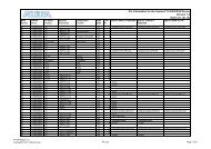
BankNumberVREFBGroup<strong>Pin</strong> Name /FunctionOptional Function(s) ConfigurationFunction<strong>Pin</strong> <strong>In<strong>for</strong>mation</strong> <strong>for</strong> <strong>the</strong> <strong>Cyclone</strong> ® <strong>II</strong> <strong>EP2C15A</strong>, <strong>EP2C20</strong> <strong>and</strong> <strong>EP2C20</strong>A DevicesVersion 2.1Notes (1), (2)Q240 F256 F484 DQS <strong>for</strong>x8/x9 inQ240DQS <strong>for</strong>x16/x18 inQ240DQS <strong>for</strong>x8/x9 inF256DQS <strong>for</strong>x16/x18 inF256DQS <strong>for</strong>x8/x9 inF484DQS <strong>for</strong>x16/x18 inF484B1 VREFB1N0 IO LVDS10n P6 DQ1L7 DQ3L7B1 VREFB1N0 IO LVDS9p R1 DQ1L8 DQ3L8B1 VREFB1N0 GND 45B1 VREFB1N0 IO LVDS9n R2B1 VREFB1N0 IO LVDS8p T1B1 VREFB1N0 IO LVDS8n T2DM1L/BWS#1LDM3L0/BWS#3L0B1 VREFB1N1 IO LVDS7p 46 M1 U1CDPCLK1/DQS3LCDPCLK1/DQS3LCDPCLK1/DQS3LCDPCLK1/DQS3LCDPCLK1/DQS3LCDPCLK1/DQS3LB1 VREFB1N1 IO LVDS7n 47 M2 U2 DQ1L2 DQ1L11 DQ1L1 DQ1L10B1 VREFB1N1 VCCIO1B1 VREFB1N1 IO LVDS6p R5 DQ3L0 DQ3L9B1 VREFB1N1 IO LVDS6n R6 DQ3L1 DQ3L10B1 VREFB1N1 IO LVDS5p V1 DQ3L2 DQ3L11B1 VREFB1N1 IO LVDS5n V2 DQ3L3 DQ3L12B1 VREFB1N1 IO LVDS4p T5 DQ3L4 DQ3L13B1 VREFB1N1 IO LVDS4n T6B1 VREFB1N1 IO M3 T3 DQ1L2 DQ1L11B1 VREFB1N1 GND 48B1 VREFB1N1 IO VREFB1N1 49 L3 U3B1 VREFB1N1 IO LVDS3p 50 N1 W1 DQ1L3 DQ1L12 DQ1L3 DQ1L12 DQ3L5 DQ3L14B1 VREFB1N1 IO LVDS3n 51 N2 W2 DQ1L4 DQ1L13 DQ1L4 DQ1L13 DQ3L6 DQ3L15B1 VREFB1N1 IO LVDS2p 52 P1 Y1 DQ1L5 DQ1L14 DQ1L5 DQ1L14 DQ3L7 DQ3L16B1 VREFB1N1 IO LVDS2n P2 Y2 DQ1L6 DQ1L15 DQ3L8 DQ3L17B1 VREFB1N1 VCCIO1 53B1 VREFB1N1 IO LVDS1p W3B1 VREFB1N1 IO LVDS1n W4B1 VREFB1N1 IO LVDS0p 54 N3 Y3 DQ1L6 DQ1L15 DQ1L7 DQ1L16B1 VREFB1N1 IO LVDS0n 55 N4 Y4 DQ1L7 DQ1L16 DQ1L8 DQ1L17DM1L/ DM1L1/B1 VREFB1N1 IO 56 P3 W5 DQ1L8 DQ1L17 BWS#1L BWS#1L1B1 VREFB1N1 IO PLL1_OUTp 57 L4 U4B1 VREFB1N1 IO PLL1_OUTn 58 M4 V4B1 VREFB1N1 GNDB1 VREFB1N1 GND_PLL1 59 L5 U5B1 VREFB1N1 VCCD_PLL1 60 L6 U6B1 VREFB1N1 GND_PLL1 61 N5 V5DM1L/BWS#1LDM1L1/BWS#1L1DM3L/BWS#3LDM3L1/BWS#3L1PT-<strong>EP2C20</strong>-2.1.xlsCopyright © 2008 Altera Corp.<strong>EP2C15A</strong>,<strong>EP2C20</strong>,<strong>EP2C20</strong>A <strong>Pin</strong> ListPage 4 of 23
BankNumberVREFBGroup<strong>Pin</strong> Name /FunctionOptional Function(s) ConfigurationFunction<strong>Pin</strong> <strong>In<strong>for</strong>mation</strong> <strong>for</strong> <strong>the</strong> <strong>Cyclone</strong> ® <strong>II</strong> <strong>EP2C15A</strong>, <strong>EP2C20</strong> <strong>and</strong> <strong>EP2C20</strong>A DevicesVersion 2.1Notes (1), (2)Q240 F256 F484 DQS <strong>for</strong>x8/x9 inQ240DQS <strong>for</strong>x16/x18 inQ240DQS <strong>for</strong>x8/x9 inF256DQS <strong>for</strong>x16/x18 inF256DQS <strong>for</strong>x8/x9 inF484DQS <strong>for</strong>x16/x18 inF484B8 VREFB8N0 IO LVDS117n R6 W9B8 VREFB8N0 IO LVDS116p 79 P6 U9 DQ1B3 DQ1B12 DQ1B3 DQ1B12DM5B/BWS#5BDM3B0/BWS#3B0B8 VREFB8N0 IO LVDS116n 80 N6 U10 DQ1B2 DQ1B11 DQ1B2 DQ1B11 DQ5B8 DQ3B8B8 VREFB8N0 GND 81B8 VREFB8N0 IO LVDS115p R10B8 VREFB8N0 IO LVDS115n R9B8 VREFB8N0 IO LVDS114p AB8 DQ5B7 DQ3B7B8 VREFB8N0 VCCINT 82B8 VREFB8N0 IO LVDS114n AA8 DQ5B6 DQ3B6B8 VREFB8N0 VCCIO8 83B8 VREFB8N0 IO VREFB8N0 84 N8 Y10B8 VREFB8N0 GND 85B8 VREFB8N0 IO LVDS113p 86 T7 AB9 DQ1B1 DQ1B10 DQ1B1 DQ1B10 DQ5B5 DQ3B5B8 VREFB8N0 IO LVDS113n 87 R7 AA9 DQ1B0 DQ1B9 DQ1B0 DQ1B9 DQ5B4 DQ3B4B8 VREFB8N0 IO LVDS112p T11B8 VREFB8N0 IO LVDS112n R11B8 VREFB8N0 IO LVDS111p W11 DQ5B3 DQ3B3B8 VREFB8N0 IO LVDS111n V11 DQ5B2 DQ3B2B8 VREFB8N0 IO LVDS110p AB10 DQ5B1 DQ3B1B8 VREFB8N0 VCCIO8B8 VREFB8N0 IO LVDS110n AA10 DQ5B0 DQ3B0B8 VREFB8N0 GNDB8 VREFB8N0 IO LVDS109p 88 T8 AB11B8 VREFB8N0 GND 89B8 VREFB8N0 IO LVDS109n 90 R8 AA11B8 VREFB8N0 CLK15 LVDSCLK7p/input(3) 91 T9 U11B8 VREFB8N0 CLK14 LVDSCLK7n/input(3) 92 R9 U12B8 VREFB8N0 VCCINT 93B7 VREFB7N1 CLK13 LVDSCLK6p/input(3) 94 N9 W12B7 VREFB7N1 CLK12 LVDSCLK6n/input(3) 95 N10 V12DPCLK3/DQS5BDPCLK4/DQS4BDPCLK3/DQS5BDM1B0/BWS#1B0DPCLK4/DQS4BDPCLK3/DQS5BDPCLK4/DQS4BDPCLK3/DQS5BDM1B0/BWS#1B0DPCLK4/DQS4BB7 VREFB7N1 IO LVDS108p 96 T11 AB12B7 VREFB7N1 VCCIO7B7 VREFB7N1 IO LVDS108n 97 R11 AA12 DM0B DQ1B8 DM0B DQ1B8B7 VREFB7N1 GNDB7 VREFB7N1 IO LVDS107p AB13 DM4BDPCLK3/DQS5BDPCLK4/DQS4BDPCLK3/DQS5BDPCLK4/DQS4BDM5B1/BWS#5B1PT-<strong>EP2C20</strong>-2.1.xlsCopyright © 2008 Altera Corp.<strong>EP2C15A</strong>,<strong>EP2C20</strong>,<strong>EP2C20</strong>A <strong>Pin</strong> ListPage 6 of 23
BankNumberVREFBGroup<strong>Pin</strong> Name /FunctionOptional Function(s) ConfigurationFunction<strong>Pin</strong> <strong>In<strong>for</strong>mation</strong> <strong>for</strong> <strong>the</strong> <strong>Cyclone</strong> ® <strong>II</strong> <strong>EP2C15A</strong>, <strong>EP2C20</strong> <strong>and</strong> <strong>EP2C20</strong>A DevicesVersion 2.1Notes (1), (2)Q240 F256 F484 DQS <strong>for</strong>x8/x9 inQ240DQS <strong>for</strong>x16/x18 inQ240DQS <strong>for</strong>x8/x9 inF256DQS <strong>for</strong>x16/x18 inF256DQS <strong>for</strong>x8/x9 inF484DQS <strong>for</strong>x16/x18 inF484B7 VREFB7N1 GND 98B7 VREFB7N1 IO LVDS107n AA13 DQ5B17B7 VREFB7N1 IO LVDS106p T12B7 VREFB7N1 IO LVDS106n U13 DQ4B7 DQ5B16B7 VREFB7N1 VCCINT 99B7 VREFB7N1 IO VREFB7N1 100 P11 Y13B7 VREFB7N1 IO R12B7 VREFB7N1 IO LVDS105p AB14 DQ4B6 DQ5B15B7 VREFB7N1 VCCIO7 101B7 VREFB7N1 IO LVDS105n AA14 DQ4B5 DQ5B14B7 VREFB7N1 GND 102B7 VREFB7N1 IO LVDS104p AB15 DQ4B4 DQ5B13B7 VREFB7N1 GND 103B7 VREFB7N1 IO LVDS104n AA15 DQ4B3 DQ5B12B7 VREFB7N1 IO LVDS103p AB16 DQ4B2 DQ5B11B7 VREFB7N1 IO LVDS103n AA16 DQ4B1 DQ5B10B7 VREFB7N1 VCCINT 104B7 VREFB7N1 IO LVDS102p W14 DQ4B0 DQ5B9B7 VREFB7N1 IO LVDS102n V14 DM2BDM5B0/BWS#5B0DPCLK5/DQS2BDPCLK5/DQS2BDPCLK5/DQS2BDPCLK5/DQS2BDPCLK5/DQS2BDPCLK5/DQS2BB7 VREFB7N1 IO LVDS101p 105 R10 AB17B7 VREFB7N1 VCCIO7B7 VREFB7N1 IO LVDS101n 106 T10 AA17 DQ0B7 DQ1B7 DQ0B7 DQ1B7B7 VREFB7N1 GNDB7 VREFB7N0 IO R13B7 VREFB7N0 GND 107B7 VREFB7N0 IO LVDS100p U14 DQ5B8B7 VREFB7N0 IO LVDS100n T15B7 VREFB7N0 IO LVDS99p Y14 DQ2B7 DQ5B7B7 VREFB7N0 VCCINT 108B7 VREFB7N0 IO LVDS99n W15 DQ2B6 DQ5B6B7 VREFB7N0 IO LVDS98p R14B7 VREFB7N0 IO LVDS98n R15B7 VREFB7N0 VCCIO7B7 VREFB7N0 IO LVDS97p 109 P12 AB18 DQ0B6 DQ1B6 DQ0B6 DQ1B6 DQ2B5 DQ5B5B7 VREFB7N0 GNDB7 VREFB7N0 IO LVDS97n 110 P13 AA18 DQ0B5 DQ1B5 DQ0B5 DQ1B5 DQ2B4 DQ5B4B7 VREFB7N0 IO VREFB7N0 111 N11 Y16PT-<strong>EP2C20</strong>-2.1.xlsCopyright © 2008 Altera Corp.<strong>EP2C15A</strong>,<strong>EP2C20</strong>,<strong>EP2C20</strong>A <strong>Pin</strong> ListPage 7 of 23
BankNumberVREFBGroup<strong>Pin</strong> Name /FunctionOptional Function(s) ConfigurationFunction<strong>Pin</strong> <strong>In<strong>for</strong>mation</strong> <strong>for</strong> <strong>the</strong> <strong>Cyclone</strong> ® <strong>II</strong> <strong>EP2C15A</strong>, <strong>EP2C20</strong> <strong>and</strong> <strong>EP2C20</strong>A DevicesVersion 2.1Notes (1), (2)Q240 F256 F484 DQS <strong>for</strong>x8/x9 inQ240B7 VREFB7N0 IO LVDS96p R16B7 VREFB7N0 GND 112B7 VREFB7N0 IO LVDS96n T16DQS <strong>for</strong>x16/x18 inQ240DQS <strong>for</strong>x8/x9 inF256DQS <strong>for</strong>x16/x18 inF256DQS <strong>for</strong>x8/x9 inF484DQS <strong>for</strong>x16/x18 inF484B7 VREFB7N0 IO LVDS95p 113 T12 U15CDPCLK3/DQS0BCDPCLK3/DQS0BCDPCLK3/DQS0BCDPCLK3/DQS0BCDPCLK3/DQS0BCDPCLK3/DQS0BB7 VREFB7N0 IO LVDS95n 114 R12 V15 DQ0B4 DQ1B4 DQ0B4 DQ1B4B7 VREFB7N0 VCCIO7 115B7 VREFB7N0B7 VREFB7N0 IO LVDS94p Y17 DQ2B3 DQ5B3B7 VREFB7N0 IO LVDS94n W16 DQ2B2 DQ5B2B7 VREFB7N0 IO LVDS93p 116 T13 AB19 DQ0B3 DQ1B3 DQ0B3 DQ1B3 DQ2B1 DQ5B1B7 VREFB7N0 IO LVDS93n 117 R13 AA19 DQ0B2 DQ1B2 DQ0B2 DQ1B2 DQ2B0 DQ5B0B7 VREFB7N0 IO LVDS92p 118 T14 AB20 DQ0B1 DQ1B1 DQ0B1 DQ1B1B7 VREFB7N0 IO LVDS92n 119 R14 AA20 DQ0B0 DQ1B0 DQ0B0 DQ1B0B7 VREFB7N0 GNDB7 VREFB7N0 GNDA_PLL4 120 M11 V16B7 VREFB7N0 VCCA_PLL4 121 L11 U16B6 VREFB6N1 GND_PLL4 122 N12 V18B6 VREFB6N1 VCCD_PLL4 123 M12 U17B6 VREFB6N1 GND_PLL4 124 L12 T17B6 VREFB6N1 GNDB6 VREFB6N1 IO 125 K13 Y18B6 VREFB6N1 IO LVDS91n INIT_DONE 126 N13 V19B6 VREFB6N1 IO LVDS91p nCEO 127 N14 W20B6 VREFB6N1 IO LVDS90n Y19B6 VREFB6N1 IO LVDS90p Y20DM1R/BWS#1RDM1R1/BWS#1R1DM1R/BWS#1RDM1R1/BWS#1R1DM3R/BWS#3RDM3R1/BWS#3R1B6 VREFB6N1 IO PLL4_OUTn 128 P15 U18B6 VREFB6N1 VCCIO6 129B6 VREFB6N1 IO PLL4_OUTp 130 P16 T18 DQ1R8 DQ1R17 DQ1R8 DQ1R17B6 VREFB6N1 IO LVDS89n 131 N15 U19 DQ1R7 DQ1R16 DQ1R7 DQ1R16 DQ3R8 DQ3R17B6 VREFB6N1 IO LVDS89p 132 N16 V20 DQ1R6 DQ1R15 DQ1R6 DQ1R15 DQ3R7 DQ3R16B6 VREFB6N1 IO LVDS88n W21 DQ3R6 DQ3R15B6 VREFB6N1 IO LVDS88p W22 DQ3R5 DQ3R14B6 VREFB6N1 GND 133B6 VREFB6N1 IO VREFB6N1 134 M14 U20B6 VREFB6N1 IO 135 P14 R17 DQ1R5 DQ1R14 DQ1R5 DQ1R14 DQ3R4 DQ3R13B6 VREFB6N1 IO LVDS87n Y21 DQ3R3 DQ3R12PT-<strong>EP2C20</strong>-2.1.xlsCopyright © 2008 Altera Corp.<strong>EP2C15A</strong>,<strong>EP2C20</strong>,<strong>EP2C20</strong>A <strong>Pin</strong> ListPage 8 of 23
BankNumberVREFBGroup<strong>Pin</strong> Name /FunctionOptional Function(s) ConfigurationFunction<strong>Pin</strong> <strong>In<strong>for</strong>mation</strong> <strong>for</strong> <strong>the</strong> <strong>Cyclone</strong> ® <strong>II</strong> <strong>EP2C15A</strong>, <strong>EP2C20</strong> <strong>and</strong> <strong>EP2C20</strong>A DevicesVersion 2.1Notes (1), (2)Q240 F256 F484 DQS <strong>for</strong>x8/x9 inQ240DQS <strong>for</strong>x16/x18 inQ240DQS <strong>for</strong>x8/x9 inF256DQS <strong>for</strong>x16/x18 inF256DQS <strong>for</strong>x8/x9 inF484DQS <strong>for</strong>x16/x18 inF484B6 VREFB6N1 IO LVDS87p Y22 DQ3R2 DQ3R11B6 VREFB6N1 IO LVDS86n V21 DQ3R1 DQ3R10B6 VREFB6N1 IO LVDS86p V22 DQ3R0 DQ3R9B6 VREFB6N1 IO LVDS85n 136 M15 U21 DQ1R4 DQ1R13 DQ1R4 DQ1R13B6 VREFB6N1 VCCIO6B6 VREFB6N1 IO LVDS85p 137 M16 U22CDPCLK4/DQS3RCDPCLK4/DQS3RCDPCLK4/DQS3RCDPCLK4/DQS3RCDPCLK4/DQS3RCDPCLK4/DQS3RB6 VREFB6N0 IO LVDS84n R18DM1R/BWS#1RDM3R0/BWS#3R0B6 VREFB6N0 IO LVDS84p R19 DQ1R8 DQ3R8B6 VREFB6N0 IO LVDS83n P17 DQ1R7 DQ3R7B6 VREFB6N0 IO LVDS83p P18 DQ1R6 DQ3R6B6 VREFB6N0 GND 138B6 VREFB6N0 IO LVDS82n T21 DQ1R5 DQ3R5B6 VREFB6N0 IO LVDS82p T22 DQ1R4 DQ3R4B6 VREFB6N0 IO LVDS81n R21 DQ1R3 DQ3R3B6 VREFB6N0 IO LVDS81p R22 DQ1R2 DQ3R2B6 VREFB6N0 IO VREFB6N0 139 L14 R20B6 VREFB6N0 IO LVDS80n 140 L15 P15 DQ1R3 DQ1R12 DQ1R3 DQ1R12B6 VREFB6N0 IO LVDS80p 141 L16 N15 DQ1R2 DQ1R11 DQ1R2 DQ1R11B6 VREFB6N0 VCCIO6 142B6 VREFB6N0 nSTATUS nSTATUS 143 M13 N20B6 VREFB6N0 GNDB6 VREFB6N0 CONF_DONE CONF_DONE 144 L13 N18B6 VREFB6N0 GND 145B6 VREFB6N0 MSEL1 MSEL1 146 K12 N17B6 VREFB6N0 MSEL0 MSEL0 147 J13 M17B6 VREFB6N0 IO LVDS79n N21 DQ1R1 DQ3R1B6 VREFB6N0 VCCINT 148B6 VREFB6N0 IO LVDS79p N22 DQ1R0 DQ3R0B6 VREFB6N0 VCCIO6B6 VREFB6N0 IO LVDS78n 149 K16 M19 DQ1R1 DQ1R10 DQ1R1 DQ1R10DPCLK6/DQS1RDPCLK6/DQS1RDPCLK6/DQS1RDPCLK6/DQS1RB6 VREFB6N0 IO LVDS78p 150 K15 M18B6 VREFB6N0 CLK7 LVDSCLK3n/input(3) 151 J16 M21B6 VREFB6N0 CLK6 LVDSCLK3p/input(3) 152 J15 M22B5 VREFB5N1 CLK5 LVDSCLK2n/input(3) 153 H15 L21B5 VREFB5N1 CLK4 LVDSCLK2p/input(3) 154 H16 L22B5 VREFB5N1 IO LVDS77n 155 H12 L19 DQ1R0 DQ1R9 DQ1R0 DQ1R9PT-<strong>EP2C20</strong>-2.1.xlsCopyright © 2008 Altera Corp.<strong>EP2C15A</strong>,<strong>EP2C20</strong>,<strong>EP2C20</strong>A <strong>Pin</strong> ListDPCLK6/DQS1RDPCLK6/DQS1RPage 9 of 23
BankNumberVREFBGroup<strong>Pin</strong> Name /FunctionOptional Function(s) ConfigurationFunction<strong>Pin</strong> <strong>In<strong>for</strong>mation</strong> <strong>for</strong> <strong>the</strong> <strong>Cyclone</strong> ® <strong>II</strong> <strong>EP2C15A</strong>, <strong>EP2C20</strong> <strong>and</strong> <strong>EP2C20</strong>A DevicesVersion 2.1Notes (1), (2)Q240 F256 F484 DQS <strong>for</strong>x8/x9 inQ240DPCLK7/DQS0RB5 VREFB5N1 IO LVDS77p 156 J12 L18DQS <strong>for</strong>x16/x18 inQ240DPCLK7/DQS0RDM1R0/BWS#1R0DQS <strong>for</strong>x8/x9 inF256DPCLK7/DQS0RDQS <strong>for</strong>x16/x18 inF256DPCLK7/DQS0RDM1R0/BWS#1R0DQS <strong>for</strong>x8/x9 inF484DPCLK7/DQS0RDQS <strong>for</strong>x16/x18 inF484DPCLK7/DQS0RDM1R1/BWS#1R1B5 VREFB5N1 IO LVDS76n 157 G16 K21 DM0RDM0RDM0RB5 VREFB5N1 VCCINT 158B5 VREFB5N1 IO LVDS76p 159 G15 K22 DQ1R8 DQ1R8 DQ1R17B5 VREFB5N1 VCCIO5 160B5 VREFB5N1 IO LVDS75n 161 F15 J21 DQ0R7 DQ1R7 DQ0R7 DQ1R7 DQ0R7 DQ1R16B5 VREFB5N1 GNDB5 VREFB5N1 IO LVDS75p 162 F16 J22 DQ0R6 DQ1R6 DQ0R6 DQ1R6 DQ0R6 DQ1R15B5 VREFB5N1 GND 163B5 VREFB5N1 IO LVDS74n J20 DQ0R5 DQ1R14B5 VREFB5N1 IO LVDS74p H19 DQ0R4 DQ1R13B5 VREFB5N1 IO VREFB5N1 164 H13 K20B5 VREFB5N1 VCCIO5B5 VREFB5N1 IO LVDS73n 165 G12 J19 DQ0R5 DQ1R5 DQ0R5 DQ1R5 DQ0R3 DQ1R12B5 VREFB5N1 IO LVDS73p 166 G13 J18 DQ0R4 DQ1R4 DQ0R4 DQ1R4 DQ0R2 DQ1R11B5 VREFB5N1 IO LVDS72n 167 E13 J17 DQ0R3 DQ1R3 DQ0R3 DQ1R3 DQ0R1 DQ1R10B5 VREFB5N1 IO LVDS72p 168 F13 H16 DQ0R2 DQ1R2 DQ0R2 DQ1R2B5 VREFB5N1 IO J15B5 VREFB5N1 GND 169B5 VREFB5N1 IO LVDS71n G21 DQ0R0 DQ1R9B5 VREFB5N1 IO LVDS71p G22 DM2RB5 VREFB5N0 IO LVDS70n 170 D15 F21DM1R0/BWS#1R0B5 VREFB5N0 IO LVDS70p 171 D16 F22CDPCLK5/DQS2RCDPCLK5/DQS2RCDPCLK5/DQS2RCDPCLK5/DQS2RCDPCLK5/DQS2RCDPCLK5/DQS2RB5 VREFB5N0 IO LVDS69n H18 DQ1R8B5 VREFB5N0 IO LVDS69p H17 DQ2R7 DQ1R7B5 VREFB5N0 IO LVDS68n E15 E21 DQ0R1 DQ1R1 DQ2R6 DQ1R6B5 VREFB5N0 VCCIO5B5 VREFB5N0 IO LVDS68p E16 E22 DQ0R0 DQ1R0 DQ2R5 DQ1R5B5 VREFB5N0 IO LVDS67n D21 DQ2R4 DQ1R4B5 VREFB5N0 IO LVDS67p D22B5 VREFB5N0 IO LVDS66n G17 DQ2R3 DQ1R3B5 VREFB5N0 IO LVDS66p G18 DQ2R2 DQ1R2B5 VREFB5N0 GND 172B5 VREFB5N0 IO VREFB5N0 173 F14 G20B5 VREFB5N0 IO LVDS65n E20 DQ2R1 DQ1R1PT-<strong>EP2C20</strong>-2.1.xlsCopyright © 2008 Altera Corp.<strong>EP2C15A</strong>,<strong>EP2C20</strong>,<strong>EP2C20</strong>A <strong>Pin</strong> ListPage 10 of 23
BankNumberVREFBGroup<strong>Pin</strong> Name /FunctionOptional Function(s) ConfigurationFunction<strong>Pin</strong> <strong>In<strong>for</strong>mation</strong> <strong>for</strong> <strong>the</strong> <strong>Cyclone</strong> ® <strong>II</strong> <strong>EP2C15A</strong>, <strong>EP2C20</strong> <strong>and</strong> <strong>EP2C20</strong>A DevicesVersion 2.1Notes (1), (2)Q240 F256 F484 DQS <strong>for</strong>x8/x9 inQ240DQS <strong>for</strong>x16/x18 inQ240DQS <strong>for</strong>x8/x9 inF256DQS <strong>for</strong>x16/x18 inF256DQS <strong>for</strong>x8/x9 inF484DQS <strong>for</strong>x16/x18 inF484B5 VREFB5N0 IO LVDS65p F20 DQ2R0 DQ1R0B5 VREFB5N0 IO LVDS64n 174 C15 C21 DQ0R1 DQ1R1B5 VREFB5N0 IO LVDS64p 175 C16 C22 DQ0R0 DQ1R0B5 VREFB5N0 VCCIO5 176B5 VREFB5N0 IO LVDS63n C19B5 VREFB5N0 IO LVDS63p C20B5 VREFB5N0 IO LVDS62n C14 D19B5 VREFB5N0 IO LVDS62p D13 D20B5 VREFB5N0 IO PLL2_OUTp 177 E14 E19B5 VREFB5N0 IO PLL2_OUTn 178 D14 E18B5 VREFB5N0 GNDB5 VREFB5N0 GND_PLL2 179 F12 F18B5 VREFB5N0 VCCD_PLL2 180 F11 F17B5 VREFB5N0 GND_PLL2 181 D12 E17B4 VREFB4N0 VCCA_PLL2 182 E12 F16B4 VREFB4N0 GNDA_PLL2 183 E11 E16B4 VREFB4N0 GNDB4 VREFB4N0 IO LVDS61n 184 B14 C18B4 VREFB4N0 IO LVDS61p 185 A14 C17 DQ0T0 DQ1T0 DQ0T0 DQ1T0B4 VREFB4N0 IO LVDS60n 186 C13 B20 DQ0T1 DQ1T1 DQ0T1 DQ1T1 DQ2T0 DQ5T0B4 VREFB4N0 IO LVDS60p 187 C12 A20 DQ0T2 DQ1T2 DQ0T2 DQ1T2 DQ2T1 DQ5T1B4 VREFB4N0 IO LVDS59n 188 B13 B19 DQ0T3 DQ1T3 DQ0T3 DQ1T3 DQ2T2 DQ5T2B4 VREFB4N0 IO LVDS59p 189 A13 A19 DQ0T4 DQ1T4 DQ0T4 DQ1T4 DQ2T3 DQ5T3B4 VREFB4N0B4 VREFB4N0 VCCIO4 190B4 VREFB4N0 IO LVDS58n 191 B12 B18 DQ0T5 DQ1T5 DQ0T5 DQ1T5CDPCLK6/DQS0TCDPCLK6/DQS0TCDPCLK6/DQS0TCDPCLK6/DQS0TCDPCLK6/DQS0TCDPCLK6/DQS0TB4 VREFB4N0 IO LVDS58p 192 A12 A18B4 VREFB4N0 IO LVDS57n G16B4 VREFB4N0 GND 193B4 VREFB4N0 IO LVDS57p H15B4 VREFB4N0 IO VREFB4N0 194 C11 C16B4 VREFB4N0 IO LVDS56n D16 DQ2T4 DQ5T4B4 VREFB4N0 GNDB4 VREFB4N0 IO LVDS56p E15 DQ2T5 DQ5T5B4 VREFB4N0 VCCIO4B4 VREFB4N0 IO LVDS55n H14B4 VREFB4N0 IO LVDS55p J14PT-<strong>EP2C20</strong>-2.1.xlsCopyright © 2008 Altera Corp.<strong>EP2C15A</strong>,<strong>EP2C20</strong>,<strong>EP2C20</strong>A <strong>Pin</strong> ListPage 11 of 23
BankNumberVREFBGroup<strong>Pin</strong> Name /FunctionOptional Function(s) ConfigurationFunction<strong>Pin</strong> <strong>In<strong>for</strong>mation</strong> <strong>for</strong> <strong>the</strong> <strong>Cyclone</strong> ® <strong>II</strong> <strong>EP2C15A</strong>, <strong>EP2C20</strong> <strong>and</strong> <strong>EP2C20</strong>A DevicesVersion 2.1Notes (1), (2)Q240 F256 F484 DQS <strong>for</strong>x8/x9 inQ240DQS <strong>for</strong>x16/x18 inQ240DQS <strong>for</strong>x8/x9 inF256DQS <strong>for</strong>x16/x18 inF256DQS <strong>for</strong>x8/x9 inF484DQS <strong>for</strong>x16/x18 inF484B4 VREFB4N0 IO LVDS54n 195 B11 D15 DQ0T6 DQ1T6 DQ0T6 DQ1T6 DQ2T6 DQ5T6B4 VREFB4N0 VCCINT 196B4 VREFB4N0 IO LVDS54p 197 A11 C14 DQ0T7 DQ1T7 DQ0T7 DQ1T7 DQ2T7 DQ5T7B4 VREFB4N0 IO LVDS53n G15B4 VREFB4N0 IO LVDS53p F15 DQ5T8B4 VREFB4N0 GND 198B4 VREFB4N1 IO H13B4 VREFB4N1 GNDB4 VREFB4N1 IO LVDS52n 199 B10 B17 DQ1T8 DQ1T8B4 VREFB4N1 VCCIO4B4 VREFB4N1 IO LVDS52p 200 A10 A17DPCLK8/DQS2TDPCLK8/DQS2TDPCLK8/DQS2TDPCLK8/DQS2TDPCLK8/DQS2TDPCLK8/DQS2TB4 VREFB4N1 IO LVDS51n E14 DM2TDM5T0/BWS#5T0B4 VREFB4N1 IO LVDS51p D14 DQ4T0 DQ5T9B4 VREFB4N1 VCCINT 201B4 VREFB4N1 IO LVDS50n F14 DQ4T1 DQ5T10B4 VREFB4N1 IO LVDS50p F13 DQ4T2 DQ5T11B4 VREFB4N1 IO LVDS49n B16 DQ4T3 DQ5T12B4 VREFB4N1 GND 202B4 VREFB4N1 IO LVDS49p A16 DQ4T4 DQ5T13B4 VREFB4N1 GNDB4 VREFB4N1 IO LVDS48n B15 DQ4T5 DQ5T14B4 VREFB4N1 VCCIO4B4 VREFB4N1 IO LVDS48p A15 DQ4T6 DQ5T15B4 VREFB4N1 IO H12B4 VREFB4N1 IO VREFB4N1 203 D9 C13B4 VREFB4N1 VCCINT 204B4 VREFB4N1 IO LVDS47n F12 DQ4T7 DQ5T16B4 VREFB4N1 IO LVDS47p G12B4 VREFB4N1 IO LVDS46n B14 DQ5T17B4 VREFB4N1 GND 205B4 VREFB4N1 IO LVDS46p A14 DM4TDM5T1/BWS#5T1B4 VREFB4N1 GND 206B4 VREFB4N1 IO LVDS45n D11 B13 DM0TDM1T0/BWS#1T0B4 VREFB4N1 VCCIO4 207B4 VREFB4N1 IO LVDS45p 208 D10 A13DPCLK9/DQS4TDPCLK9/DQS4TDPCLK9/DQS4TDPCLK9/DQS4TDPCLK9/DQS4TDPCLK9/DQS4TPT-<strong>EP2C20</strong>-2.1.xlsCopyright © 2008 Altera Corp.<strong>EP2C15A</strong>,<strong>EP2C20</strong>,<strong>EP2C20</strong>A <strong>Pin</strong> ListPage 12 of 23
BankNumberVREFBGroup<strong>Pin</strong> Name /FunctionOptional Function(s) ConfigurationFunction<strong>Pin</strong> <strong>In<strong>for</strong>mation</strong> <strong>for</strong> <strong>the</strong> <strong>Cyclone</strong> ® <strong>II</strong> <strong>EP2C15A</strong>, <strong>EP2C20</strong> <strong>and</strong> <strong>EP2C20</strong>A DevicesVersion 2.1Notes (1), (2)Q240 F256 F484 DQS <strong>for</strong>x8/x9 inQ240B4 VREFB4N1 CLK8 LVDSCLK4n/input(3) 209 A9 B12B4 VREFB4N1 CLK9 LVDSCLK4p/input(3) 210 B9 A12B3 VREFB3N0 VCCINT 211B3 VREFB3N0 CLK10 LVDSCLK5n/input(3) 212 A8 D12B3 VREFB3N0 CLK11 LVDSCLK5p/input(3) 213 B8 E12DQS <strong>for</strong>x16/x18 inQ240DQS <strong>for</strong>x8/x9 inF256DQS <strong>for</strong>x16/x18 inF256DM1T0/BWS#1T0 DQ1T0 DQ1T9DQS <strong>for</strong>x8/x9 inF484DQS <strong>for</strong>x16/x18 inF484B3 VREFB3N0 IO LVDS44n 214 A7 B11 DM0TB3 VREFB3N0 GND 215DPCLK10/ DPCLK10/ DPCLK10/ DPCLK10/ DPCLK10/B3 VREFB3N0 IO LVDS44p 216 B7 A11 DQS5T DQS5T DQS5T DQS5T DQS5TB3 VREFB3N0 GNDB3 VREFB3N0 IO LVDS43n E11 DQ5T0 DQ3T0B3 VREFB3N0 VCCIO3B3 VREFB3N0 IO LVDS43p D11 DQ5T1 DQ3T1B3 VREFB3N0 IO LVDS42n H11B3 VREFB3N0 IO LVDS42p G11B3 VREFB3N0 IO LVDS41n B10 DQ5T2 DQ3T2B3 VREFB3N0 IO LVDS41p A10 DQ5T3 DQ3T3B3 VREFB3N0 IO LVDS40n F11 DQ5T4 DQ3T4B3 VREFB3N0 IO LVDS40p F10 DQ5T5 DQ3T5B3 VREFB3N0 GND 217B3 VREFB3N0 IO VREFB3N0 218 D8 C10B3 VREFB3N0 VCCIO3 219B3 VREFB3N0 IO LVDS39n B9 DQ5T6 DQ3T6B3 VREFB3N0 VCCINT 220B3 VREFB3N0 IO LVDS39p A9 DQ5T7 DQ3T7B3 VREFB3N0 IO LVDS38n H10B3 VREFB3N0 IO LVDS38p H9B3 VREFB3N0 GND 221B3 VREFB3N0 IO LVDS37n E9 DQ5T8 DQ3T8B3 VREFB3N0 IO LVDS37p D9B3 VREFB3N0 IO LVDS36n 222 B6 B8 DQ1T0 DQ1T9 DQ1T1 DQ1T10B3 VREFB3N0 GNDDPCLK11/ DPCLK11/ DPCLK11/ DPCLK11/B3 VREFB3N0 IO LVDS36p 223 A6 A8 DQS3T DQS3T DQS3T DQS3TDM5T/BWS#5TDPCLK11/DQS3TDPCLK10/DQS5TDM3T0/BWS#3T0DPCLK11/DQS3TB3 VREFB3N1 VCCIO3B3 VREFB3N1 IO LVDS35n B7 DQ3T0 DQ3T9B3 VREFB3N1 VCCINT 224B3 VREFB3N1 IO LVDS35p A7 DQ3T1 DQ3T10PT-<strong>EP2C20</strong>-2.1.xlsCopyright © 2008 Altera Corp.<strong>EP2C15A</strong>,<strong>EP2C20</strong>,<strong>EP2C20</strong>A <strong>Pin</strong> ListPage 13 of 23
BankNumberVREFBGroup<strong>Pin</strong> Name /FunctionOptional Function(s) ConfigurationFunction<strong>Pin</strong> <strong>In<strong>for</strong>mation</strong> <strong>for</strong> <strong>the</strong> <strong>Cyclone</strong> ® <strong>II</strong> <strong>EP2C15A</strong>, <strong>EP2C20</strong> <strong>and</strong> <strong>EP2C20</strong>A DevicesVersion 2.1Notes (1), (2)Q240 F256 F484 DQS <strong>for</strong>x8/x9 inQ240DQS <strong>for</strong>x16/x18 inQ240DQS <strong>for</strong>x8/x9 inF256DQS <strong>for</strong>x16/x18 inF256DQS <strong>for</strong>x8/x9 inF484DQS <strong>for</strong>x16/x18 inF484B3 VREFB3N1 IO LVDS34n F9 DQ3T2 DQ3T11B3 VREFB3N1 IO LVDS34p E8 DQ3T3 DQ3T12B3 VREFB3N1 GND 225B3 VREFB3N1 IO LVDS33n D8 DQ3T4 DQ3T13B3 VREFB3N1 IO LVDS33p C9 DQ3T5 DQ3T14B3 VREFB3N1 IO 226 D7 D7 DQ1T1 DQ1T10 DQ1T2 DQ1T11 DQ3T6 DQ3T15B3 VREFB3N1 GND 227B3 VREFB3N1 IO LVDS32n 228 D6 F8 DQ1T2 DQ1T11 DQ1T3 DQ1T12 DQ3T7 DQ3T16B3 VREFB3N1 VCCIO3 229B3 VREFB3N1 IO LVDS32p 230 C6 G8 DQ1T3 DQ1T12 DQ1T4 DQ1T13B3 VREFB3N1 IO H8B3 VREFB3N1 IO VREFB3N1 231 C5 C7B3 VREFB3N1 IO 232 C4 E7 DQ1T4 DQ1T13 DQ1T5 DQ1T14 DQ3T8 DQ3T17B3 VREFB3N1 IO LVDS31n G7B3 VREFB3N1 IO LVDS31p H7B3 VREFB3N1 IO LVDS30n 233 B5 B6 DQ1T5 DQ1T14 DQ1T6 DQ1T15B3 VREFB3N1 GNDB3 VREFB3N1 IO LVDS30p 234 A5 A6B3 VREFB3N1 VCCIO3CDPCLK7/DQS1TCDPCLK7/DQS1TCDPCLK7/DQS1TCDPCLK7/DQS1TB3 VREFB3N1 IO LVDS29n B5B3 VREFB3N1 IO LVDS29p A5B3 VREFB3N1 IO LVDS28n 235 B4 B4 DQ1T6 DQ1T15 DQ1T7 DQ1T16B3 VREFB3N1 IO LVDS28p 236 A4 A4 DQ1T7 DQ1T16 DQ1T8 DQ1T17DM1T/ DM1T1/B3 VREFB3N1 IO LVDS27p 237 A3 A3 DQ1T8 DQ1T17 BWS#1T BWS#1T1B3 VREFB3N1 IO LVDS27n DEV_CLRn 238 B3 B3B3 VREFB3N1 GNDB3 VREFB3N1 GNDA_PLL3 239 E6 F7B3 VREFB3N1 VCCA_PLL3 240 F6 E6VCCINT F9 J10VCCINT F10 J11VCCINT G7 J12VCCINT G9 J13VCCINT G11 K9VCCINT H7 K14VCCINT H10 L9PT-<strong>EP2C20</strong>-2.1.xlsCopyright © 2008 Altera Corp.DM1T/BWS#1T<strong>EP2C15A</strong>,<strong>EP2C20</strong>,<strong>EP2C20</strong>A <strong>Pin</strong> ListDM1T1/BWS#1T1CDPCLK7/DQS1TDM3T/BWS#3TCDPCLK7/DQS1TDM3T1/BWS#3T1Page 14 of 23
BankNumberVREFBGroup<strong>Pin</strong> Name /FunctionOptional Function(s) ConfigurationFunction<strong>Pin</strong> <strong>In<strong>for</strong>mation</strong> <strong>for</strong> <strong>the</strong> <strong>Cyclone</strong> ® <strong>II</strong> <strong>EP2C15A</strong>, <strong>EP2C20</strong> <strong>and</strong> <strong>EP2C20</strong>A DevicesVersion 2.1Notes (1), (2)Q240 F256 F484 DQS <strong>for</strong>x8/x9 inQ240VCCINT H11 L14VCCINT J6 M9VCCINT J7 M14VCCINT J10 N9VCCINT K6 N14VCCINT K8 P10VCCINT K10 P11VCCINT L7 P12VCCINT L8 P13VCCIO2 B1 B1VCCIO2J7VCCIO2 G3 L3VCCIO1 K3 AA1VCCIO1M3VCCIO1P7VCCIO1 R1 T4VCCIO8 M7 AB2VCCIO8T9VCCIO8 P7 V10VCCIO8W6VCCIO8 T2 Y11VCCIO7 M10 AB21VCCIO7T14VCCIO7 P10 V13VCCIO7W17VCCIO7 T15 Y12VCCIO6 K14 AA22VCCIO6M20VCCIO6 R16 P16VCCIO6T19VCCIO5 B16 B22VCCIO5G19VCCIO5J16VCCIO5 G14 L20VCCIO4 A15 A21VCCIO4 C10 C12VCCIO4D17VCCIO4E13VCCIO4 E10 G14DQS <strong>for</strong>x16/x18 inQ240DQS <strong>for</strong>x8/x9 inF256DQS <strong>for</strong>x16/x18 inF256DQS <strong>for</strong>x8/x9 inF484DQS <strong>for</strong>x16/x18 inF484PT-<strong>EP2C20</strong>-2.1.xlsCopyright © 2008 Altera Corp.<strong>EP2C15A</strong>,<strong>EP2C20</strong>,<strong>EP2C20</strong>A <strong>Pin</strong> ListPage 15 of 23
BankNumberVREFBGroup<strong>Pin</strong> Name /FunctionOptional Function(s) ConfigurationFunction<strong>Pin</strong> <strong>In<strong>for</strong>mation</strong> <strong>for</strong> <strong>the</strong> <strong>Cyclone</strong> ® <strong>II</strong> <strong>EP2C15A</strong>, <strong>EP2C20</strong> <strong>and</strong> <strong>EP2C20</strong>A DevicesVersion 2.1Notes (1), (2)Q240 F256 F484 DQS <strong>for</strong>x8/x9 inQ240VCCIO3 A2 A2VCCIO3C6VCCIO3 C7 C11VCCIO3E10VCCIO3 E7 G9GND F7 K10GND F8 K11GND G6 K12GND G8 K13GND G10 L10GND H6 L11GND H8 L12GND H9 L13GND J8 M10GND J9 M11GND J11 M12GND K7 M13GND K9 N10GND K11 N11GND L9 N12GND L10 N13GND A1 A1GNDA22GND A16 AA2GND B2 AA21GNDAB1GNDAB22GND B15 B2GND C8 B21GNDC5GNDC8GND C9 C15GNDD10GND E8 D13GND E9 D18GNDF19GND H3 G4GNDG10GNDG13DQS <strong>for</strong>x16/x18 inQ240DQS <strong>for</strong>x8/x9 inF256DQS <strong>for</strong>x16/x18 inF256DQS <strong>for</strong>x8/x9 inF484DQS <strong>for</strong>x16/x18 inF484PT-<strong>EP2C20</strong>-2.1.xlsCopyright © 2008 Altera Corp.<strong>EP2C15A</strong>,<strong>EP2C20</strong>,<strong>EP2C20</strong>A <strong>Pin</strong> ListPage 16 of 23
BankNumberVREFBGroup<strong>Pin</strong> Name /FunctionOptional Function(s) ConfigurationFunction<strong>Pin</strong> <strong>In<strong>for</strong>mation</strong> <strong>for</strong> <strong>the</strong> <strong>Cyclone</strong> ® <strong>II</strong> <strong>EP2C15A</strong>, <strong>EP2C20</strong> <strong>and</strong> <strong>EP2C20</strong>A DevicesVersion 2.1Notes (1), (2)Q240 F256 F484 DQS <strong>for</strong>x8/x9 inQ240GND H14 H20GND J3 K3GNDK7GNDK16GND J14 K19GND M8 M4GNDN7GNDN16GND M9 N19GND P8 R3GNDT10GND P9 T13GNDT20GNDV3GND R2 V6GND R15 V17GNDW10GND T1 W13GNDW19GNDY8GND T16 Y15NCG1NCG2NCH21NCH22NCJ3NCJ5NCJ6NCJ8NCJ9NCK8NCK15NCK17NCK18NCL7NCL15NCL16NCL17NCM7DQS <strong>for</strong>x16/x18 inQ240DQS <strong>for</strong>x8/x9 inF256DQS <strong>for</strong>x16/x18 inF256DQS <strong>for</strong>x8/x9 inF484DQS <strong>for</strong>x16/x18 inF484PT-<strong>EP2C20</strong>-2.1.xlsCopyright © 2008 Altera Corp.<strong>EP2C15A</strong>,<strong>EP2C20</strong>,<strong>EP2C20</strong>A <strong>Pin</strong> ListPage 17 of 23
BankNumberVREFBGroup<strong>Pin</strong> Name /FunctionNCNCNCNCNCNCNCNCNCNCNCNCNCOptional Function(s) ConfigurationFunction<strong>Pin</strong> <strong>In<strong>for</strong>mation</strong> <strong>for</strong> <strong>the</strong> <strong>Cyclone</strong> ® <strong>II</strong> <strong>EP2C15A</strong>, <strong>EP2C20</strong> <strong>and</strong> <strong>EP2C20</strong>A DevicesVersion 2.1Notes (1), (2)Q240 F256 F484 DQS <strong>for</strong>x8/x9 inQ240M8M15M16N5N8P4P14P19P20P21P22R4W18DQS <strong>for</strong>x16/x18 inQ240DQS <strong>for</strong>x8/x9 inF256DQS <strong>for</strong>x16/x18 inF256DQS <strong>for</strong>x8/x9 inF484DQS <strong>for</strong>x16/x18 inF484Notes:(1) The optional functions (e.g. LVDS, DDR) are not available <strong>for</strong> some pins in certain packages.For example, <strong>for</strong> <strong>the</strong> EP2C8 device, <strong>the</strong> LVDS70 pair is available <strong>for</strong> <strong>the</strong> Q208 <strong>and</strong> F256 packages, but not <strong>for</strong> <strong>the</strong> T144 package.(2) The DQS0T, DQS1T, DQS0B, <strong>and</strong> DQS1B pin functions are only available in <strong>the</strong> F672 <strong>and</strong> F896 packages.(3) If <strong>the</strong> dedicated CLK pins are not used to feed <strong>the</strong> global clock networks, <strong>the</strong>y can be used as general-purpose input pins to feed <strong>the</strong> core logic.The dedicated CLK pins do not support <strong>the</strong> I/O register.PT-<strong>EP2C20</strong>-2.1.xlsCopyright © 2008 Altera Corp.<strong>EP2C15A</strong>,<strong>EP2C20</strong>,<strong>EP2C20</strong>A <strong>Pin</strong> ListPage 18 of 23
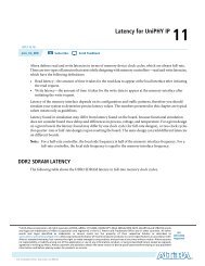
<strong>Pin</strong> NameVCCINT<strong>Pin</strong> <strong>In<strong>for</strong>mation</strong> <strong>for</strong> <strong>the</strong> <strong>Cyclone</strong> ® <strong>II</strong> <strong>EP2C15A</strong>, <strong>EP2C20</strong> <strong>and</strong> <strong>EP2C20</strong>A DevicesVersion 2.1Note (1)<strong>Pin</strong> Type (1st, 2nd, <strong>and</strong>3rd Function) <strong>Pin</strong> Description Connection GuidelinesSupply <strong>and</strong> Reference <strong>Pin</strong>sPowerThese are internal logic array voltage supply pins. VCCINT also supplies power to <strong>the</strong> input buffersused <strong>for</strong> <strong>the</strong> LVPECL, LVDS (regular I/O <strong>and</strong> CLK pins), differential HSTL, <strong>and</strong> differential SSTL I/Ost<strong>and</strong>ards.Connect all VCCINT pins to 1.2 V. Decoupling depends on <strong>the</strong> design decoupling requirementsof <strong>the</strong> specific board. (Note 2)These are I/O supply voltage pins <strong>for</strong> banks 1 through 8. Each bank can support a different voltageVCCIO[1..8]Powerlevel. VCCIO supplies power to <strong>the</strong> output buffers <strong>for</strong> all I/O st<strong>and</strong>ards. VCCIO also supplies power to<strong>the</strong> input buffers used <strong>for</strong> <strong>the</strong> LVTTL, LVCMOS, 1.5-V, 1.8-V, 2.5-V, 3.3-V PCI, <strong>and</strong> 3.3-V PCI-X,differential SSTL, differential HSTL, <strong>and</strong> LVDS (regular I/O) I/O st<strong>and</strong>ards.Verify that <strong>the</strong> VCCIO voltage level connected is consistent with <strong>the</strong> .pin report from <strong>the</strong> Quartus ®<strong>II</strong> software. Decoupling depends on <strong>the</strong> design decoupling requirements of <strong>the</strong> specific board.(Note 2)GND Ground Device ground pins. Connect all GND pins to <strong>the</strong> board GND plane.If voltage-referenced I/O st<strong>and</strong>ards are not used in <strong>the</strong> bank, <strong>the</strong> VREF pins are available as userInput reference voltage <strong>for</strong> each I/O bank. If a bank uses a voltage-referenced I/O st<strong>and</strong>ard, <strong>the</strong>n <strong>the</strong>se I/O pins. Decoupling depends on <strong>the</strong> design decoupling requirements of <strong>the</strong> specific board. (NoteVREFB[1..8]N[0..3]I/Opins are used as <strong>the</strong> voltage-referenced pins <strong>for</strong> <strong>the</strong> bank.2)VCCA_PLL[1..4](Note 4) Power Analog power <strong>for</strong> PLLs[1..4].Connect <strong>the</strong>se pins to 1.2 V, even if <strong>the</strong> PLL is not used. Use an isolated linear supply <strong>for</strong> betterjitter per<strong>for</strong>mance. You can connect all VCCA_PLL pins to a single linear supply to minimize cost.Power on <strong>the</strong> PLLs should be decoupled. Decoupling depends on <strong>the</strong> design decouplingrequirements of <strong>the</strong> specific board (Note 2) . For more in<strong>for</strong>mation on this pin, refer to <strong>the</strong> PLLs in<strong>Cyclone</strong> <strong>II</strong> Devices chapter in <strong>the</strong> <strong>Cyclone</strong> <strong>II</strong> Device H<strong>and</strong>book.VCCD_PLL[1..4](Note 4) Power Digital power <strong>for</strong> PLLs[1..4].Connect <strong>the</strong>se pins to <strong>the</strong> quietest digital supply on board (1.2 V), which is also supplied to <strong>the</strong>VCCINT, even if <strong>the</strong> PLL is not used. Power on <strong>the</strong> PLLs should be decoupled. Decouplingdepends on <strong>the</strong> design decoupling requirements of <strong>the</strong> specific board (Note 2) . For morein<strong>for</strong>mation on this pin, refer to <strong>the</strong> PLLs in <strong>Cyclone</strong> <strong>II</strong> Devices chapter in <strong>the</strong> <strong>Cyclone</strong> <strong>II</strong> DeviceH<strong>and</strong>book.GNDA_PLL[1..4](Note 4) Ground Analog ground <strong>for</strong> PLLs[1..4].Connect <strong>the</strong>se pins directly to <strong>the</strong> same ground plane as <strong>the</strong> digital ground of <strong>the</strong> device, even if<strong>the</strong> PLL is not used. For more in<strong>for</strong>mation on this pin, refer to <strong>the</strong> PLLs in <strong>Cyclone</strong> <strong>II</strong> Deviceschapter in <strong>the</strong> <strong>Cyclone</strong> <strong>II</strong> Device H<strong>and</strong>book.GND_PLL[1..4](Note 4) Ground Ground <strong>for</strong> PLLs[1..4]. Connect <strong>the</strong>se pins to <strong>the</strong> GND plane on <strong>the</strong> board.NC No Connect No Connect Do not drive signals into <strong>the</strong>se pins.Dedicated Configuration/JTAG <strong>Pin</strong>sDCLKInput (PS)Output (AS)Dedicated configuration clock pin. In PS configuration, DCLK is used to clock configuration data froman external source into <strong>the</strong> <strong>Cyclone</strong> <strong>II</strong> device. In AS mode, DCLK is an output from <strong>the</strong> <strong>Cyclone</strong> <strong>II</strong>device that provides timing <strong>for</strong> <strong>the</strong> configuration interface. The input buffer on this pin supportshysteresis using <strong>the</strong> Schmitt trigger circuitry.DCLK should not be left floating. You should drive it high or low, whichever is more convenient on<strong>the</strong> board.Dedicated configuration data input pin. In serial configuration modes, bit-wide configuration data isreceived through this pin. In AS mode, DATA0 has an internal pull-up resistor that is always active. The DATA0 should not be left floating. You should drive it high or low, whichever is more convenientDATA0Inputinput buffer on this pin supports hysteresis using <strong>the</strong> Schmitt trigger circuitry.on <strong>the</strong> board.MSEL[0..1] Input Configuration input pins that set <strong>the</strong> <strong>Cyclone</strong> <strong>II</strong> device configuration scheme.These pins must be hardwired to VCCIO of <strong>the</strong> bank <strong>the</strong>y reside in or GND. Do not leave <strong>the</strong>sepins floating. When <strong>the</strong>se pins are unused, connect <strong>the</strong>m to GND. For MSEL pin settings <strong>for</strong>different configuration schemes, refer to <strong>the</strong> Configuring <strong>Cyclone</strong> <strong>II</strong> Devices chapter in <strong>the</strong><strong>Cyclone</strong> <strong>II</strong> Device H<strong>and</strong>book.nCEnCONFIGInputInputDedicated active-low chip enable. When nCE is low, <strong>the</strong> device is enabled. When nCE is high, <strong>the</strong>device is disabled. The input buffer on this pin supports hysteresis using <strong>the</strong> Schmitt trigger circuitry.Dedicated configuration control input. Pulling this pin low during user mode causes <strong>the</strong> FPGA to loseits configuration data, enter a reset state, <strong>and</strong> tri-state all I/O pins. Returning this pin to a logic highlevel initiates reconfiguration. The input buffer on this pin supports hysteresis using <strong>the</strong> Schmitt triggercircuitry.In a multi-device configuration, nCE of <strong>the</strong> first device is tied low while its nCEO pin drives <strong>the</strong>nCE of <strong>the</strong> next device in <strong>the</strong> chain. In a single-device configuration, nCE is tied low.nCONFIG should be pulled high by an external 10-kΩ pull-up resistor to a 3.3-V supply. If <strong>the</strong>configuration scheme uses an enhanced configuration device or EPC2, nCONFIG can be tieddirectly to <strong>the</strong> nINIT_CONF pin of <strong>the</strong> configuration device. If this pin is not used, this pin can beconnected through a resistor to VCCIO.CONF_DONEBidirectional(open-drain)This is a dedicated configuration status pin. As a status output, <strong>the</strong> CONF_DONE pin drives low be<strong>for</strong>e<strong>and</strong> during configuration. Once all configuration data is received without error <strong>and</strong> <strong>the</strong> initializationcycle starts, CONF_DONE is released. As a status input, CONF_DONE goes high after all data isreceived. Then <strong>the</strong> device initializes <strong>and</strong> enters user mode. It is not available as a user I/O pin. Theinput buffer on this pin supports hysteresis using <strong>the</strong> Schmitt trigger circuitry.CONF_DONE should be pulled high by an external 10-kΩ pull-up resistor to a 3.3-V supply. Ifinternal pull-up resistors on <strong>the</strong> enhanced configuration device are used, external 10-kΩ pull-upresistors should not be used on this pin.PT-<strong>EP2C20</strong>-2.1.xlsCopyright © 2008 Altera Corp. <strong>Pin</strong> Definitions Page 19 of 23
nSTATUSTCKTMSBidirectional(open-drain)InputInputThis is a dedicated configuration status pin. The FPGA drives nSTATUS low immediately after powerup<strong>and</strong> releases it after POR time. As a status output, <strong>the</strong> nSTATUS is pulled low if an error occursduring configuration. As a status input, <strong>the</strong> device enters an error state when nSTATUS is driven lowby an external source during configuration or initialization. It is not available as a user I/O pin. Theinput buffer on this pin supports hysteresis using <strong>the</strong> Schmitt trigger circuitry.Dedicated JTAG clock input pin. This pin has weak internal pull-down resistors. The input buffer on thispin supports hysteresis using <strong>the</strong> Schmitt trigger circuitry.Dedicated JTAG input pin that provides <strong>the</strong> control signal to determine <strong>the</strong> transitions of <strong>the</strong> TAPcontroller state machine. This pin has weak internal pull-up resistors. The input buffer on this pinsupports hysteresis using <strong>the</strong> Schmitt trigger circuitry.nSTATUS should be pulled high by an external 10-kΩ pull-up resistor to a 3.3-V supply.Connect this pin to GND via a 1-kΩ resistor. If <strong>the</strong> JTAG circuitry is not used, connect TCK toGND.Connect this pin to a 1-kΩ resistor via <strong>the</strong> VCCIO of <strong>the</strong> bank it resides in. If <strong>the</strong> JTAG circuitry isnot used, connect TMS to VCCIO.Dedicated JTAG test data input pin <strong>for</strong> instructions, <strong>and</strong> test <strong>and</strong> programming data. This pin has weakTD<strong>II</strong>nputinternal pull-up resistors. The input buffer on this pin supports hysteresis using <strong>the</strong> Schmitt triggercircuitry.Connect this pin to a 1-kΩ resistor via <strong>the</strong> VCCIO of <strong>the</strong> bank it resides in. If <strong>the</strong> JTAG circuitry isnot used, connect TDI to VCCIO.TDO Output Dedicated JTAG data output pin <strong>for</strong> instructions, <strong>and</strong> test <strong>and</strong> programming data. When not in JTAG mode, this pin should be left unconnected.Clock <strong>and</strong> PLL <strong>Pin</strong>sCLK[0,2,4,6,8,10,12,14], LVDSCLK[0..7]pClock, InputDedicated global clock input pins that can also be used <strong>for</strong> <strong>the</strong> positive terminal inputs <strong>for</strong> differentialglobal clock input or user input pins.Connect unused pins to GND.CLK[1,3,5,7,9,11,13,15], LVDSCLK[0..7]nClock, InputDedicated global clock input pins that can also be used <strong>for</strong> <strong>the</strong> negative terminal inputs <strong>for</strong> differentialglobal clock input or user input pins.Connect unused pins to GND.PLL[1..4]_OUTp(Note 4)I/O, OutputOptional positive terminal <strong>for</strong> external clock outputs from PLLs[1..4]. These pins can only use <strong>the</strong>differential I/O st<strong>and</strong>ard if it is being fed by a PLL output.When not used as PLL output pins, <strong>the</strong>se pins can be used as user I/O pins. When <strong>the</strong>se pinsare not used, <strong>the</strong>y may be left floating.PLL[1..4]_OUTn(Note 4)I/O, OutputOptional negative terminal <strong>for</strong> external clock outputs from PLLs[1..4]. These pins can only use <strong>the</strong>differential I/O st<strong>and</strong>ard if it is being fed by a PLL output.Optional/Dual-Purpose Configuration <strong>Pin</strong>snCEO I/O, Output Output that drives low when device configuration is complete.nCSOASDOI/O, OutputI/O, OutputOutput control signal from <strong>the</strong> <strong>Cyclone</strong> <strong>II</strong> FPGA to <strong>the</strong> nCS pin of <strong>the</strong> serial configuration device in ASmode that enables <strong>the</strong> configuration device by driving it low. In AS mode, <strong>the</strong> nCSO has internal weakpull-up resistor, which is always active.When not used as PLL output pins, <strong>the</strong>se pins can be used as user I/O pins. When <strong>the</strong>se pinsare not used, <strong>the</strong>y may be left floating.During a multi-device configuration, this pin feeds <strong>the</strong> nCE pin of a subsequent device <strong>and</strong> mustbe pulled high to VCCIO by an external 10-kΩ pull-up resistor. During a single-deviceconfiguration <strong>and</strong> <strong>for</strong> <strong>the</strong> last device in a multi-device configuration, this pin can be leftunconnected or used as an user I/O after configuration.When not programming <strong>the</strong> device in AS mode, <strong>the</strong> nCSO pin can be used as user I/O. Whenthis pin is not used as an I/O, Altera recommends that you leave <strong>the</strong> pin unconnected.Output control signal from <strong>the</strong> <strong>Cyclone</strong> <strong>II</strong> FPGA to <strong>the</strong> serial configuration device in AS mode used toread out configuration data. In AS mode, <strong>the</strong> ASDO has internal weak pull-up resistor, which is always When not programming <strong>the</strong> device in AS mode, <strong>the</strong> ASDO pin can be used as user I/O. Whenactive.this pin is not used as an I/O, Altera recommends that you leave <strong>the</strong> pin unconnected.CRC_ERRORDEV_CLRnDEV_OEINIT_DONECLKUSRI/O, OutputI/O (when option off),Input (when option on)I/O (when option off),Input (when option on)I/O, Output(open-drain)I/O, InputActive-high signal that indicates <strong>the</strong> error-detection circuit has detected errors in <strong>the</strong> configurationSRAM bits. This pin is optional <strong>and</strong> is used when <strong>the</strong> CRC error-detection circuit is enabled.Optional chip-wide reset pin that allows you to override all clears on all device registers. When this pinis driven low, all registers are cleared; when this pin is driven high, all registers behave asprogrammed. The DEV_CLRn pin does not affect JTAG boundary-scan or programming operations.This pin is enabled by turning on <strong>the</strong> Enable device-wide reset (DEV_CLRn) option in <strong>the</strong> Quartus <strong>II</strong>software.Optional pin that allows you to override all tri-states on <strong>the</strong> device. When this pin is driven low, all I/Opins are tri-stated; when this pin is driven high, all I/O pins behave as defined in <strong>the</strong> design. This pin isenabled by turning on <strong>the</strong> Enable device-wide output enable (DEV_OE) option in <strong>the</strong> Quartus <strong>II</strong>software.This is a dual-purpose status pin <strong>and</strong> can be used as an I/O pin when not enabled as INIT_DONE.When enabled, a transition from low to high at <strong>the</strong> pin indicates when <strong>the</strong> device has entered usermode. If <strong>the</strong> INIT_DONE output is enabled, <strong>the</strong> INIT_DONE pin cannot be used as a user I/O pin afterconfiguration. This pin is enabled by turning on <strong>the</strong> Enable INIT_DONE output option in <strong>the</strong> Quartus <strong>II</strong>software.Optional user-supplied clock input. Synchronizes <strong>the</strong> initialization of one or more devices. If this pin isnot enabled <strong>for</strong> use as a user-supplied configuration clock, it can be used as a user I/O pin. This pin isenabled by turning on <strong>the</strong> Enable user-supplied start-up clock (CLKUSR) option in <strong>the</strong> Quartus <strong>II</strong>software.Dual-Purpose Differential & External Memory Interface <strong>Pin</strong>sWhen <strong>the</strong> dedicated output <strong>for</strong> CRC_ERROR is not used <strong>and</strong> this pin is not used as an I/O,Altera recommends that you leave <strong>the</strong> pin unconnected.When <strong>the</strong> dedicated output <strong>for</strong> DEV_CLRn is not used <strong>and</strong> this pin is not used as an I/O, Alterarecommends that you tie this pin to <strong>the</strong> VCCIO of <strong>the</strong> bank that it resides in or ground. (Note 6)When <strong>the</strong> dedicated output <strong>for</strong> DEV_OE is not used <strong>and</strong> this pin is not used as an I/O, Alterarecommends that you tie this pin to <strong>the</strong> VCCIO of <strong>the</strong> bank that it resides in or ground. (Note 6)When INIT_DONE is enabled, connect this pin to a 10-kΩ resistor via <strong>the</strong> VCCIO of <strong>the</strong> bank thatit resides in.If <strong>the</strong> CLKUSR pin is not used as a configuration clock input <strong>and</strong> <strong>the</strong> pin is not used as an I/O,Altera recommends that you connect this pin to ground.LVDS[0-256][p,n](Note 3)I/O, TX/RX channelDual-purpose differential transmitter/receiver channels 0 to 256. These channels can be used <strong>for</strong>transmitting or receiving LVDS-compatible signals. <strong>Pin</strong>s with a "p" suffix carry <strong>the</strong> positive signal <strong>for</strong> <strong>the</strong>differential channel. <strong>Pin</strong>s with an "n" suffix carry <strong>the</strong> negative signal <strong>for</strong> <strong>the</strong> differential channel. If not When <strong>the</strong>se pins are not used, <strong>the</strong>y can be tied to <strong>the</strong> VCCIO of <strong>the</strong> bank that <strong>the</strong>y reside in orused <strong>for</strong> differential signaling, <strong>the</strong>se pins are available as user I/O pins.GND. (Note 6)PT-<strong>EP2C20</strong>-2.1.xlsCopyright © 2008 Altera Corp. <strong>Pin</strong> Definitions Page 20 of 23
DPCLK[0..11]/DQS[[0,1]L,[3,5,4,2]B,[1,0]R,[2,4,5,3]T] (Note 5)I/O, DPCLK/DQSDual-purpose DPCLK/DQS pins can connect to <strong>the</strong> global clock network <strong>for</strong> high-fanout control signalssuch as clocks, asynchronous clears, presets, <strong>and</strong> clock enables. It can also be used as optional datastrobe signal <strong>for</strong> use in external memory interfacing. These pins drive to dedicated DQS phase-shiftcircuitry, which allows <strong>for</strong> <strong>the</strong> fine-tuning of <strong>the</strong> phase shift <strong>for</strong> input clocks or strobes to properly alignclock edges needed to capture data.When <strong>the</strong>se pins are not used, <strong>the</strong>y can be tied to <strong>the</strong> VCCIO of <strong>the</strong> bank that <strong>the</strong>y reside in orGND. (Note 6)CDPCLK[0..7]/DQS[[2,3]L,[1,0]B,[3,2]R,[0,1]T](Note 5)I/O, CDPCLK/DQSDual-purpose CDPCLK/DQS pins can connect to <strong>the</strong> global clock network <strong>for</strong> high-fanout controlsignals such as clocks, asynchronous clears, presets, <strong>and</strong> clock enables. Only one of <strong>the</strong> two CDPCLKin each corner can feed <strong>the</strong> clock control block at a time. The o<strong>the</strong>r pin can be used as a generalpurposeI/O pin. The CDPCLK signals incur more delay to <strong>the</strong> clock block control because <strong>the</strong>y aremultiplexed be<strong>for</strong>e being driven into <strong>the</strong> clock block control. It can also be used as optional data strobesignal <strong>for</strong> use in external memory interfacing. These pins drive to dedicated DQS phase-shift circuitry,which allows <strong>for</strong> <strong>the</strong> fine-tuning of <strong>the</strong> phase shift <strong>for</strong> input clocks or strobes to properly align clock When <strong>the</strong>se pins are not used, <strong>the</strong>y can be tied to <strong>the</strong> VCCIO of <strong>the</strong> bank that <strong>the</strong>y reside in oredges needed to capture data.GND. (Note 6)When <strong>the</strong>se pins are not used, <strong>the</strong>y can be tied to <strong>the</strong> VCCIO of <strong>the</strong> bank that <strong>the</strong>y reside in orGND. (Note 6)When <strong>the</strong>se pins are not used, <strong>the</strong>y can be tied to <strong>the</strong> VCCIO of <strong>the</strong> bank that <strong>the</strong>y reside in orGND. (Note 6)DQ[[[1,3][L,R]],[[3,5][B,T]]][0..17](Note 5) I/O, DQ Optional data signal <strong>for</strong> use in external memory interfacing in <strong>the</strong> x16 or x18 modes.DQ[[[0..3][L,R]],[[0..5][B,T]]][0..8](Note 5) I/O, DQ Optional data signal <strong>for</strong> use in external memory interfacing in <strong>the</strong> x8 or x9 modes.DM[[[0..3][L,R]],[[0..5][B,T]]](Note 5 )I/O, DMOptional data mask pins <strong>for</strong> x8/x9 modes are required when writing to DDR SDRAM <strong>and</strong> DDR2SDRAM devices. A low signal indicates that <strong>the</strong> write is valid. If <strong>the</strong> DM signal is high, <strong>the</strong> memorymasks <strong>the</strong> DQ signals. Each group of DQ <strong>and</strong> DQS signals requires a DM pin.When <strong>the</strong>se pins are not used, <strong>the</strong>y can be tied to <strong>the</strong> VCCIO of <strong>the</strong> bank that <strong>the</strong>y reside in orGND. (Note 6)DM[[[1,3][L,R]],[[3,5][B,T]]][0,1](Note 5 )DM[[[0..3][L,R]],[[0..5][B,T]]](Note 5)DM[[[1,3][L,R]],[[3,5][B,T]]][0,1](Note 5 )I/O, DMI/O, BWSI/O, BWSOptional data mask pins <strong>for</strong> x16/x18 modes are required when writing to DDR SDRAM <strong>and</strong> DDR2SDRAM devices. A low signal indicates that <strong>the</strong> write is valid. If <strong>the</strong> DM signal is high, <strong>the</strong> memorymasks <strong>the</strong> DQ signals. Each group of DQ <strong>and</strong> DQS signals requires a DM pin.When <strong>the</strong>se pins are not used, <strong>the</strong>y can be tied to <strong>the</strong> VCCIO of <strong>the</strong> bank that <strong>the</strong>y reside in orGND. (Note 6)Byte Write Select is an active-low pin. When asserted active, BWS selects which byte is written into<strong>the</strong> device during write operation. Bytes not written remain unchanged. Deselecting BWS causes write When <strong>the</strong>se pins are not used, <strong>the</strong>y can be tied to <strong>the</strong> VCCIO of <strong>the</strong> bank that <strong>the</strong>y reside in ordata to be ignored <strong>and</strong> not written into device.GND. (Note 6)Byte Write Select is an active-low pin. When asserted active, BWS selects which byte is written into<strong>the</strong> device during write operation. Bytes not written remain unchanged. Deselecting BWS causes write When <strong>the</strong>se pins are not used, <strong>the</strong>y can be tied to <strong>the</strong> VCCIO of <strong>the</strong> bank that <strong>the</strong>y reside in ordata to be ignored <strong>and</strong> not written into device.GND. (Note 6)Altera provides <strong>the</strong>se guidelines only as recommendations. It is <strong>the</strong> responsibility of <strong>the</strong> designer to apply simulation results to <strong>the</strong> design to verify proper device functionality.Notes:1) These pin connection guidelines are created based on <strong>the</strong> largest <strong>Cyclone</strong> <strong>II</strong> device, EP2C70F896. Refer to <strong>the</strong> pin list <strong>for</strong> <strong>the</strong> availability of pins in each density.2) Capacitance values <strong>for</strong> <strong>the</strong> power supply should be selected after considering <strong>the</strong> amount of power <strong>the</strong>y need to supply over <strong>the</strong> frequency of operation of <strong>the</strong> particular circuit being decoupled. A target impedance <strong>for</strong> <strong>the</strong> power plane should be calculated based on current draw<strong>and</strong> voltage droop requirements of <strong>the</strong> device or supply. The power plane should <strong>the</strong>n be decoupled using <strong>the</strong> appropriate number of capacitors. On-board capacitors do not decouple higher than 100 MHz due to “Equivalent Series Inductance” of <strong>the</strong> mounting of <strong>the</strong> packages.Proper board design techniques such as interplaning capacitance with low inductance should be considered <strong>for</strong> higher frequency decoupling.3) The differential transmitter/receiver channel count <strong>for</strong> each device <strong>and</strong> package is different; smaller packages may contain less than <strong>the</strong> maximum number of differential transmitter/receiver channels. For details on <strong>the</strong> differential transmitter/receiver channel count <strong>for</strong> eachdevice, refer to <strong>the</strong> corresponding pin-out from www.altera.com.4) The EP2C5, EP2C8, <strong>and</strong> EP2C8A devices have only PLL1 <strong>and</strong> PLL2.5) The DQ, DQS, DM, <strong>and</strong> BWS# bus mode count <strong>for</strong> each device <strong>and</strong> package is different. Smaller packages may contain less than <strong>the</strong> maximum number of DQ, DQS, DM, <strong>and</strong> BWS# bus modes. For details on <strong>the</strong> DQ, DQS, DM, <strong>and</strong> BWS# bus mode count <strong>for</strong> each device,refer to <strong>the</strong> corresponding pin-out from www.altera.com.6) Make sure that unused pins are set to input tristated in <strong>the</strong> Quartus <strong>II</strong> software. For instructions on how to set this, refer to <strong>the</strong> Quartus <strong>II</strong> H<strong>and</strong>book.PT-<strong>EP2C20</strong>-2.1.xlsCopyright © 2008 Altera Corp. <strong>Pin</strong> Definitions Page 21 of 23
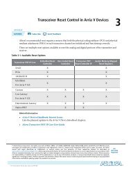
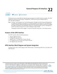
<strong>Pin</strong> <strong>In<strong>for</strong>mation</strong> <strong>for</strong> <strong>the</strong> <strong>Cyclone</strong> ® <strong>II</strong> <strong>EP2C15A</strong>, <strong>EP2C20</strong> & <strong>EP2C20</strong>A Devices, ver 2.1PLL3VREFB3N1 VREFB3N0 VREFB4N1B3B4VREFB4N0PLL2VREFB1N1 VREFB1N0 VREFB2N1 VREFB2N0B1B2B6 B5VREFB6N1 VREFB6N0 VREFB5N1 VREFB5N0B8B7PLL1VREFB8N1 VREFB8N0 VREFB7N1VREFB7N0PLL4Notes:1. This is a top view of <strong>the</strong> silicon die.2. This is only a pictorial representation to get an idea of placement on <strong>the</strong> device.Refer to <strong>the</strong> pin list <strong>and</strong> <strong>the</strong> Quartus ® <strong>II</strong> software <strong>for</strong> exact locations.PT-<strong>EP2C20</strong>-2.1.xlsCopyright © 2008 Altera Corp.Bank & PLL DiagramPage 22 of 23
<strong>Pin</strong> <strong>In<strong>for</strong>mation</strong> <strong>for</strong> <strong>the</strong> <strong>Cyclone</strong> ® <strong>II</strong> <strong>EP2C15A</strong>, <strong>EP2C20</strong> & <strong>EP2C20</strong>A DevicesVersion 2.1Version Number Date Changes Made1.0 10/6/2004 Initial revision1.1 1/10/2005 Added CRC_ERROR pin in <strong>Pin</strong> List <strong>and</strong> <strong>Pin</strong> DefinitionChanged pin name from GNDD_PLL <strong>and</strong> GNDG_PLL to GND_PLLFor F256 package:LVDS19p changed from pin E1 to E3LVDS19n changed from pin E2 to E4LVDS16p changed from pin F1 to E1LVDS16n changed from pin F2 to E2TDI changed from pin G1 to H5TCK changed from pin G2 to F2TMS changed from pin H5 to J1TDO changed from pin E4 to G2DATA0 changed from pin E3 to F11.2 2/24/2005 Modified <strong>Pin</strong> Definitions <strong>for</strong> DATA0 pin5/7/2005 Finalize1.3 5/25/2005 Added Q240 package1.4 6/2/2005 Modified <strong>Pin</strong> Type column in <strong>Pin</strong> Definitions <strong>for</strong> VREFB[1..8]N[0..1] pins1.5 2/10/2006 Added footnote <strong>for</strong> pins that do not support Optional Functions (LVDS, DDR, etc)Added footnote <strong>for</strong> DQS0T, DQS1T, DQS0B <strong>and</strong> DQS1B pinsModified pin definition <strong>for</strong> NC pinsModified <strong>Pin</strong> Description of VREFB[1..8]N[0..1] pinsModified <strong>Pin</strong> Description of VCCA_PLL[1..4] <strong>and</strong> VCCD_PLL[1..4] pinsAdded <strong>Pin</strong> Description <strong>for</strong> BWS pins1.6 3/1/2006 Added comment <strong>for</strong> PLL_OUT pins in <strong>Pin</strong> Definitions1.7 5/9/2006 Modified "DQS <strong>for</strong> x16/x18 in Q240" column from DQ0B[3:0] to DQ1B[3:0] in <strong>Pin</strong> List1.8 6/16/2006 Added <strong>EP2C15A</strong> <strong>and</strong> <strong>EP2C20</strong>A support1.9 11/13/2006 Modified <strong>Pin</strong> Description of VCCIO <strong>and</strong> VCCINT.Added "I/O" to pin type of pin nCEO, nCSO <strong>and</strong> ASDOMoved nCEO Discription from section "Dedicated Configuration/JTAG <strong>Pin</strong>s" to section"Optional/Dual-Purpose Configuration <strong>Pin</strong>s"2.0 3/7/2007 Modified <strong>Pin</strong> Description <strong>for</strong> MSEL2.1 5/2/2008 Incorporated pin connection guidelines into pin definitions worksheet.PT-<strong>EP2C20</strong>-2.1.xlsCopyright © 2008 Altera Corp.Revision HistoryPage 23 of 23