Cyclone V SoC FPGA Development Board Reference Manual - Altera
Cyclone V SoC FPGA Development Board Reference Manual - Altera
Cyclone V SoC FPGA Development Board Reference Manual - Altera

Create successful ePaper yourself
Turn your PDF publications into a flip-book with our unique Google optimized e-Paper software.
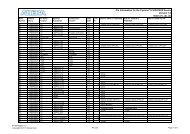
Chapter 2: <strong>Board</strong> Components 2–3<strong>Board</strong> OverviewTable 2–1. <strong>Board</strong> Components (Part 2 of 3)<strong>Board</strong> <strong>Reference</strong> Type DescriptionSW3S11MSEL DIP switchProgram select push buttonControls the configuration scheme on the board. MSEL pins 0, 1, 2 and4 connects to the DIP switch while MSEL pin 3 connects to ground.Toggles the program select LEDs, which selects the program imagethat loads from flash memory to the <strong>FPGA</strong>.S12Configure push buttonLoad image from flash memory to the <strong>FPGA</strong> based on the settings ofthe program select LEDs.D37 Configuration done LED Illuminates when the <strong>FPGA</strong> is configured.D34Load LEDIlluminates when the MAX V CPLD 5M2210 System Controller isactively configuring the <strong>FPGA</strong>.D36 Error LED Illuminates when the <strong>FPGA</strong> configuration from flash memory fails.D35 Power LED Illuminates when 5.0-V power is present.D30, D31 JTAG TX/RX LEDsIndicate the transmit or receive activity of the JTAG chain. The TX andRX LEDs would flicker if the link is in use and active. The LEDs areeither off when not in use or on when in use but idle.D39–D41 Program select LEDsIlluminates to show which flash memory image loads to the <strong>FPGA</strong>when you press the program select push button. Refer to Table 2–6 forthe LED settings.D9 HSMC port present LED Illuminates when a daughter card is plugged into the HSMC port.D14, D15 UART LEDs Illuminates when UART transmitter and receiver are in use.Clock CircuitryX1Programmable oscillatorProgrammable oscillator with a default frequency of 100 MHz. Thefrequency is programmable using the clock control GUI running on theMAX V CPLD 5M2210 System Controller.X4 50-MHz oscillator 50.000-MHz crystal oscillator for general purpose logic.X3148.5-MHz oscillatorProgrammable voltage-controlled crystal oscillator (VCXO) with adefault frequency of 148.5 MHz. The frequency is programmable usingthe clock control GUI running on the MAX V CPLD 5M2210 SystemController.J36 Clock input SMA connector Drive CMOS-compatible clock inputs into the clock multiplexer buffer.U29U35Multi-output oscillatorMulti-output oscillatorSi5338C quad-output programmable oscillator with 100M, 25M, 25M,and 156.25M outputs.Si5338C quad-output fixed oscillator with 25M, 25M, 100M, and 100Moutputs.General User Input/OutputD1–D8 User LEDs Eight user LEDs. Illuminates when driven low.SW1 User DIP switch User DIP switch. When the switch is ON, a logic 0 is selected.S10 CPU reset push button Reset the <strong>FPGA</strong> logic.S2 MAX V reset push button Reset the MAX V CPLD 5M2210 System Controller.S1–S6 General user push buttons Six user push buttons. Driven low when pressed.Memory DevicesU37, U38, U30,Two 4-Gbit DDR3 SDRAM with a 16-bit data bus for the <strong>FPGA</strong> andDDR3 memoryU22, U14three 4-Gbit DDR3 SDRAM with a 16-bit data bus for the HPS.U5 QSPI flash 1-Gb serial NOR flash with 4-bit data bus.November 2013 <strong>Altera</strong> Corporation <strong>Cyclone</strong> V <strong>SoC</strong> <strong>Development</strong> <strong>Board</strong><strong>Reference</strong> <strong>Manual</strong>