Winegard Sensar Antenna Installation/Operation ... - Dutchmen RV
Winegard Sensar Antenna Installation/Operation ... - Dutchmen RV
Winegard Sensar Antenna Installation/Operation ... - Dutchmen RV

Create successful ePaper yourself
Turn your PDF publications into a flip-book with our unique Google optimized e-Paper software.
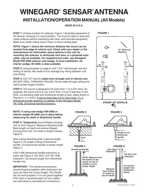
–WINEGARD®®SENSAR ANTENNAINSTALLATION/OPERATION MANUAL (All Models)MADE IN U.S.A.STEP 1: Choose location for antenna. Figure 1 illustrates placement ofthe <strong>Sensar</strong>, showing it in travel position. You must be able to raise androtate antenna without interfering with other roof-mounted equipment.Make sure inside ceiling area is clear to mount ceiling plate.FIGURE 1NOTE: Figure 1 shows the minimum distance the mount can belocated from edge of vehicle roof. Check with your dealer or themanufacturer for information about options in the roof formounting the antenna. A reinforced roof area, or a prewired coaxcable, may be available. For sloped/round roofs, use <strong>Winegard</strong>Model RW-2000 exterior roof wedge, to level installation. Aninterior wedge, IW-5000, is also available.10" MinimumDistanceSTEP 2: Using template on page 6, drill 1-3/4" hole through roof andceiling of vehicle. Be careful not to damage any wiring between roofand ceiling.STEP 3: Drill 1/2" hole for cable entry through roof of vehicle only.DO NOT DRILL THROUGH CEILING. Route cable through ceiling andwall to power supply location.STEP 4: The mount is designed to fit roofs from 1" to 4-3/4" thick. Assupplied, the mount will fit a roof 4-3/4" thick. If roof is less than 4-3/4"thick, cut elevating shaft and directional handle to size, steps shown inFigures 2, 3, 4 and 5. If roof is more than 4-3/4" thick (max. 7"), adirectional handle extension is needed. Order <strong>Winegard</strong> ModelEK-1036, Directional Handle Extension.NOTE: If using roof wedge RW-2000 orinterior wedge IW-5000, put in place beforemeasuring for shaft or directional handle.FIGURE 2∗FIGURE 3STEP 5: Temporarily mount lift/gear housingunit on roof, Figure 2. Measure elevating shaft,Mark length on shaft and remove lift/gearhousing from roof. Cut shaft to length marked,Figure 3.After cutting elevating shaft, measure length,Figure 4, for proper cutting of directionalhandle. Cut directional handle to proper length,Figure 4.If EK-1036 (directional handle extension) isused, see Figure 5. DO NOT CUT EK-1036extension. Cut excess length from directionalhandle only.IMPORTANT: The handle and extensionshould be glued together after checking to besure you have the correct length. The handlewill not work properly if it is not glued together!(PVC glue is recommended; for your safety,use according to manufacturer's directions.)11-1/2"FIGURE 4Directional HandleEK-1036ExtensionNOTE: Measure fromthe bottom of therecess on top ofhandle & cut toproper lengthMeasurefrom bottom–of recess ontop of handleLength to cutdirectionalhandleFIGURE 5•2-1/4"DO NOT CUT– extension•–Cut excesslength fromdirectionalhande<strong>Installation</strong>/<strong>Operation</strong> 2452035
OPERATION (All Models)RAISING ANTENNA TO OPERATING POSITIONTurn elevating crank (clockwise) in “UP” directionabout 13 turns or until some resistance to turning isnoted.AMPLIFIED MODELS ONLYTurn power supply ON to use either front or rearTV outlet. Neither outlet will work unless powersupply switch is ON.WARNINGDO NOT connect highcurrent devices such ashair dryers to thisreceptacle. Maximumcurrent rating of thisreceptacle is 8 amps at+12 VDC.LUBRICATIONSTEP 1: To lubricate the elevating gear, apply aliberal amount of silicone spray lubricant to theelevating gear with the lift in the down position (seeillustration). Run the lift up and down to distribute thelubricant over gears.STEP 2: Two times yearly, or in the event rotating theantenna becomes difficult, normal operation can berestored by lubricating the bearing surface betweenthe rotating gear housing and the base plate. Anysilicone lubricant spray may be used. Elevateantenna and remove set screw or plastic plug fromrotating gear housing as shown. Spray lubricant intohole and around edges of gear housing. Rotate gearhousing until lubricant coats bearing surfaces andantenna rotates freely.Lubricate HereSpray Around EdgesRemove plug,spraylubricant into holeROTATING ANTENNA FOR BEST PICTUREMake sure antenna is in“UP” position. Pull downon both hands until itdisengages ceiling plateand rotate for best picture.LOWERING ANTENNA TO TRAVEL POSITIONRotate antenna until pointer on directional handlealigns with pointer on ceiling plate. Turn elevatingcrank (counter clockwise) in “DOWN” direction about13 turns or until resistance is noted. <strong>Antenna</strong> is nowlocked in travel position.IMPORTANT: Under no conditions lower antennain any position except travel position.LUBRICATING RUBBER QUAD RINGLubricate rubber quad ring on elevatingshaft which is below worm gear withsilicone spray lubricant at least twiceyearly. This will keep quad ring frombecoming brittle which could result inleaks down elevating shaft. Refer topage 8 for removing worm gearassembly. Item #6 on parts explosion.WaveWasherFlatWasherRubberRingDO’S1. Check parking location for obstructions before raisingantenna.2. Carefully raise, lower and rotate. If this is difficult,check for cause.3. Rotate slowly when selecting station and check finetuning on TV set to make sure it is properly adjusted.4. Lower antenna before moving vehicle.DONT'S1. Don’t force elevating crank up or down.2. Don’t rotate directional handle hard against stops.3. Don’t travel with lift in up position.4. Don’t leave lift part way up or down.5. Don’t apply sealing compound or paint over top of baseplate or anywhere on lift.4
INSTALLING F-CONNECTORS ON COAXIAL CABLEStep 1. Strip outer cover back 1/2"* from end of cable. Fray braid back as far as outercover will allow.Step 2. Trim braid close to outer cover and remove 1/4"* of inner insulation beingcareful not to nick center conductor. Make sure no foil or braid can touch centerconductor.Step 3. Slide connector tip between braid and inner insulation (braid and foil, on foilshield cable) and push connector on cable as far as it will go. Crimp built-in ferrule withproper crimping tool. Hex connector requires hex crimping tool. Do Not crushcable out-of-round.* If installing in very hot weather, increase these dimensions 1/8".WHAT TO DO WHEN YOUR <strong>RV</strong>/TV ANTENNA IS NOT WORKING PROPERLYHOW YOUR SYSTEM WORKS, Figure 1WARNINGDo not install couplers, splitters, etc. between thepower supply and the antenna. <strong>Installation</strong> of anyitem on the downlead may cause a short in thesystem. The downlead supplies +12 VDC to thepreamp in the antenna.Figure 1+12 VDCAmplifiedTV Signal2ND SetHook UpNo +12 VDCat this pointSet 2Turning power supply on sends +12 VDC up cableto antenna. Voltage energizes transistors onamplifier in antenna head. TV signal comes backdown cable to outlets.TO TEST SYSTEM, Figure 21. Make sure TV set is working properly.2. Switch power supply ON and OFF to differencein picture quality while watching TV. If NO there isdifference, use following steps.CAUTION: The power supply should be turnedOFF when connecting/disconnecting cables topower supply and antenna, but should be turnedON when testing for voltage.3. Disconnect cable from antenna and check for+12 VDC at Test Point #1. If there is +12 VDC, thepower supply is OK. Replace antenna.4. If there is NO +12 VDC at Test Point #1,reconnect cable to antenna. Remove powersupply from wall and visually inspect for burned/broken parts. If there are ANY broken/burnedparts, replace power supply.5. Disconnect cable from antenna jack on powersupply. Check for +12 VDC at Test Point 2. If +12VDC is present, there is a cable problemconnecting the power supply to the antenna.Repair/replace cable6. If +12 VDC is not present at Test Point # 2, besure the green indicator light is ON. If not, checkthe polarity of the red/white wires and the +12VDC source. If there is still no +12 VDC, replacepower supply.Figure 2<strong>Antenna</strong>ConnectionTEST POINT #1+12 VDC at <strong>Antenna</strong>+12 VDCat<strong>Antenna</strong>JackTESTPOINT #2Red+12 VDCRed+12 VDCSet 2ConnectionWhiteGND.WhiteGND.2ND SetNo +12 VDCat this point5
ORDERING REPAIR PARTSRepair parts are available at many <strong>RV</strong> dealers and/or service centers throughout the country. If you don'thave a dealer/service center near you, call <strong>Winegard</strong> Company at 1-800-288-8094. All major credit cardsaccepted. Parts are available only in the packages shown here. Order by the Model No. of the packageneeded. Example: To order the elevating gear, order RP-3000. Tax, shipping and handling additional.112PACKAGE MODEL NO. PRICE<strong>RV</strong>2001A 82.13Amplified<strong>Antenna</strong> Head75 ohm2120430 39.75Non-Amplified<strong>Antenna</strong> Head75 ohmRP-2900 17.162 Elevator Tubes2 Grommets4 Pins4 Retaining RingsRubber BumperSelf Drilling Sc.PACKAGE MODEL NO. PRICE7 RP-2049 27.39Gear Housing2 PinsBearingNut *BearingO-Ring SealRetaining Ring* Remove/tighten with 15/16" 12 socket.8RP-3523 13.40Base Plate10 RP-2049 ScrewsRubber Boot9RP-6200IVORYDirectional HandleCeiling Plate4 ScrewsSpringDecal5.5212435FOR MODELS MADEBEFORE 199034RP-2000Leveling Mount4 Spacers2 Pins2 RingsRP-0154Boot6.111.509 RP-6300WHITEDirectional HandleCeiling Plate4 ScrewsSpringDecal1011RP-6822SpringRP-2658Nylon Bearing5.521.981.4067WaveWasherFlat WasherRubberQuad Ring135614RP-3000Elevating GearRP-4000Worm Gear &12.25" HexElevating ShaftAssembly w/Wave WasherFlat Washer"O" RingWorm Gear NutRW-5000Roof Wedge5.0010.954.95AFTER 1989NEW 1993FITS ALL161212****13SeeDrawingat RightRP-5895IVORYCrank, Set Screw,Hex ShaftRP-6795WHITECrank, Set Screw,Hex ShaftSA-1001 IVORYPreassembledElev. Shaft, GearHsg.,Base PlateEK-1036DirectionalHandleExtension6.286.2871.502.378791091112** Use 3/32Allen Wrenchfor set screw15 IW-1000Interior Wedge2.006Rev. 1/04
<strong>RV</strong>-3090/4090/5090 TEMPLATE(Template)1/2" DIA.NOTE: DO NOT DRILLTHOUGH CEILING INEXPOSED AREA.1-3/4" DIA.DRILL COMPLETELYTHROUGH CEILINGTOWARD FRONTOF VEHICLE1/8" DRILL BIT10 HOLES. DO NOTDRILL THROUGH CEILING.MINIMUM OF 5 FT.CLEAR SPACE7
SENSAR ANTENNA/LIFT TWO YEAR LIMITED WARRANTY<strong>Winegard</strong> Company warrants this <strong>Winegard</strong> product against any defects in materials or workmanship within two (2) years from date ofpurchase. No warranty claim will be honored unless at the time the claim is made, you present proof of purchase to an authorized <strong>Winegard</strong>dealer (if unknown, please contact <strong>Winegard</strong> Company, 3000 Kirkwood Street, Burlington, Iowa 52601-2000, telephone 319-754-0600).<strong>Winegard</strong> Company (at its option) will either repair or replace the defective product at no charge to you. This warranty covers parts, butdoes not cover any costs incurred in removal, shipping or reinstallation of the product. This limited warranty does not apply if the productis damaged, deteriorates, malfunctions or fails from: misuse, improper installation, abuse, neglect, accident, tampering, modification of theproduct as originally manufactured by <strong>Winegard</strong>, usage not in accordance with product instructions or acts of nature such as damage causedby wind, lightning, ice or corrosive environments such as salt spray and acid rain. (SENSAR ® ) This limited warranty does not apply if anyother antenna is mounted to the SENSAR lift, if any other lift is mounted to the SENSAR antenna, or if the SENSAR antenna receivingelements are modified in any manner whatsoever.The Two Year Warranty is provided on the condition that the equipment is properly delivered with all handling and freight charges prepaidto your <strong>Winegard</strong> dealer for repair or return to our factory at the above address. <strong>Winegard</strong> dealers will arrange for the replacement or repairand return to you, without charge, the product which failed due to defective material or workmanship.WINEGARD COMPANY WILL NOT ASSUME ANY LIABILITIES FOR ANY OTHER WARRANTIES, EXPRESS OR IMPLIED, MADE BYANY OTHER PERSON.ALL OTHER WARRANTIES WHETHER EXPRESS, IMPLIED OR STATUTORY INCLUDING WARRANTIES OF FITNESS FOR APARTICULAR PURPOSE AND MERCHANTABILITY ARE LIMITED TO THE TWO YEAR PERIOD OF THIS WRITTEN WARRANTY.The foregoing shall be the sole and exclusive remedy of any person whether in contract, tort or otherwise, and <strong>Winegard</strong> shall not be liablefor incidental or consequential damage or commercial loss, or from any other loss or damage except as set forth above.Some states do not allow limitations on how long an implied warranty lasts, or the exclusion of limitation of incidental or consequentialdamages, so the above limitations or exclusions may not apply to you.This warranty gives you specific legal rights and you may also have other rights which vary from state to state.ELEVATING SHAFT & WORM GEAR ASSEMBLY REPLACEMENT PROCEDURENOTE: It is not necessary to remove rotating gear housing from base plate or remove antenna fromroof to replace the shaft & worm gear assembly .Step 1: Lower antenna to travel position. Loosen set screw on elevating crank , remove crank, spring ,directional handle.Step 2: Remove top retaining ring from top pin holding top elevating tube in rotating gear housing andremove pin.Step 3: Remove plastic plug from top of rotating gear housing, disengage elevating gear, remove elevatingshaft assembly .Step 4: Lubricate worm gear assembly on new elevating shaft assembly with spray silicone lubricant,make sure wave washer, flat washer and quad ring are on lower bearing and insert assembly in housing.Step 5: Reinstall plastic plug in top of housing. Gears will mesh automatically once elevating crank isturned.Step 6: Replace directional handle, spring and elevating crank. Make sure set screw contacts flat surfaceon shaft before tightening.Printed in U.S.A. <strong>Winegard</strong> Company • 3000 Kirkwood Street • 8Burlington, Iowa 52601-2000 © <strong>Winegard</strong> Company, 2004 2452035