ElectroMelt System Design Guide - California Detection Systems
ElectroMelt System Design Guide - California Detection Systems
ElectroMelt System Design Guide - California Detection Systems
- No tags were found...

Create successful ePaper yourself
Turn your PDF publications into a flip-book with our unique Google optimized e-Paper software.
<strong>ElectroMelt</strong> <strong>System</strong><strong>Design</strong> <strong>Guide</strong><strong>ElectroMelt</strong> <strong>System</strong><strong>Design</strong>Basic <strong>ElectroMelt</strong> <strong>System</strong> <strong>Design</strong>The power produced by <strong>ElectroMelt</strong> EM2-XR heating cable installed on 12-inch centersis adequate for the majority of concrete-pavement snow-melting and anti-icing systems.For this reason, the design steps in the next section and information in other <strong>ElectroMelt</strong>literature are based on this spacing.In addition, information in this guide and in other <strong>ElectroMelt</strong> literature is based on thestandard application of the EM2-XR heating cable in concrete pavement poured on gradeonly.<strong>ElectroMelt</strong> system literature includes the following:• <strong>ElectroMelt</strong> <strong>System</strong> Brochure H53391• <strong>ElectroMelt</strong> <strong>System</strong> <strong>Design</strong> <strong>Guide</strong> H53393• <strong>ElectroMelt</strong> <strong>System</strong> Installation and Operation Manual H53392<strong>Design</strong> for Standard ApplicationsThe basic <strong>ElectroMelt</strong> system design for standard applications on grade is adequate formost snowfall and icing conditions, allowing no snow accumulation 97 percent of thetime. The design keeps the pavement surface at or above freezing when the air above thepavement is at 5°F and the wind is steady at 10 miles per hour or less.Because the design information in this guide applies only to standard concrete pavementpoured on grade, it should not be used for other applications.<strong>Design</strong> Requirements and AssumptionsThe design for standard applications is based on the following assumptions with regardto the concrete and the heating cable:Concrete:Heating cable:• 4 to 6 inches thick • 12-inch cable spacing• Placed on grade • Secured to reinforcing steel or mesh• Standard density • Located 1 1 ⁄2 to 2 inches belowfinished surfaceWARNING: Concrete cracks that extend to the depth of the cable may damage thecable and create the risk of fire. Install the cable in pavement or slabs that have beendesigned for long-term structural integrity.<strong>Design</strong> for Nonstandard ApplicationsIncreased Power and Performance RequirementsSome applications and some locations require more snow-melting power or more completeanti-icing protection than the standard 12-inch spacing provides. For these cases,refer to the Supplemental <strong>Design</strong> Information section of this guide for more detailed performanceinformation and design data for nonstandard applications.For nonstandard applications, contact your Raychem representative for assistance withyour design. Using proprietary computer modeling based on a finite difference programfor nonstandard applications, Raychem can design the appropriate system for a nonstandardapplication.The following are some nonstandard applications:• concrete thinner than 4 inches• concrete thicker than 6 inches• Iightweight concrete• concrete with pavers thicker than 1 1 ⁄2 inches• ramps and walkways with air below• nonconcrete pavements• concrete without reinforcing• retrofitting of heating cable to existing pavement8
<strong>ElectroMelt</strong> <strong>System</strong><strong>Design</strong> <strong>Guide</strong><strong>Design</strong> StepsStep 1.Determine Heating-Cable SpacingFor most standard applications, <strong>ElectroMelt</strong> EM2-XR heating cable may be installed on12-inch centers. The design steps that follow are based on 12-inch spacing.Snowfall and icing conditions vary widely with location. For this reason, heating cableinstalled on 12-inch centers may not provide adequate performance for every location.To determine correct heating-cable spacing for a particular location, consult theSupplemental <strong>Design</strong> Information section of this guide.Step 2.Lay Out Heating CableFor uniform heating, arrange the heating cable in a serpentine pattern that covers the area.Space the cable on 12-inch centers or use alternate spacing determined by consulting theSupplemental <strong>Design</strong> Information section of this guide.Maintain the heating cable spacing in the design within 1 inch.Use these symbols to indicate the heating cable and components:PESPower ConnectionEnd SealSpliceDo not route the heating cable closer than 4 inches to the edge of the pavement, drains,anchors, or other material in the concrete.The water resulting from the melted snow or ice should run into a drain or off to a safearea.Arrange the heating cable so that both ends of the cable terminate in an above-ground,UL Listed or CSA Certified weatherproof junction box. The following are guidelines forthis procedure:• Mount the heating-cable junction box above grade to prevent water entry. Use anEMK-XJB or equivalent UL Listed or CSA Certified weatherproof junction box.• Protect the heating cable from the pavement to the junction box by installing heatingcable inside individual 1-inch rigid metal conduits. Minimize the length of the protectiveconduit. Do not penetrate building walls or floors with the protective conduit orinsulate the conduit.• Extend the conduit approximately 6 inches into the concrete for support.• Provide bushings on both ends of each conduit.• Do not install more than one run of heating cable per conduit.• Minimize the length of the conduit.• Do not insulate the conduit.• Do not penetrate building floors or walls with the conduit.If possible avoid crossing expansion, crack-control, or other pavement joints. Wherecrossing a joint is unavoidable, use the EMK-XEJ expansion joint kit to protect the heatingcable.Use these symbols to indicate the location of the joints:Expansion JointCrack-control jointExpansion joint kit9
<strong>ElectroMelt</strong> <strong>System</strong><strong>Design</strong> <strong>Guide</strong><strong>Design</strong> StepsCalculate the total length of heating cable required as:Total heating Heated area (ft 2 ) x 12=+end+cable length componentHeating cable spacing (in.) allowances a allowances ba End allowance is the length of heating cable installed between the heated area and the powerconnection junction box, measured in feet.b Component allowances measured in feet (see page 7).Junction BoxEMK-XJBEP6" (S/2) 12" (S) 1" Conduit6"6" (S/2) S = Heating cable spacingStep 3.Determine Electrical ParametersThis section will help you determine the electrical parameters for an <strong>ElectroMelt</strong> system.To determine the demands an <strong>ElectroMelt</strong> system will place on your electrical equipment,refer to “Electrical Performance Requirements” in the Supplemental <strong>Design</strong> Informationsection of this guide.Electrical ProtectionThe installation and design of the <strong>ElectroMelt</strong> <strong>System</strong> is governed by Article 426 of theNational Electrical Code. Your installation must also comply with all applicable localcodes and standards. To comply with the National Electrical Code, use a 30-mA groundfaultprotection device (GFEPD).WARNING: To minimize the danger of fire from sustained electrical arcing if the heatingcable is damaged or improperly installed, use a ground-fault protection devicewith a 30-mA trip level. Electrical fault currents may be too small to trip conventionalcircuit breakers.VoltageStandard design information is provided for operation at 208 Vac. The allowable range ofvoltage for EM2-XR is 200 to 277 Vac. Using a voltage higher than 208 volts results inslightly higher surface temperatures and allows longer maximum circuit lengths as indicatedin Tables 1 and 2.10
<strong>ElectroMelt</strong> <strong>System</strong><strong>Design</strong> <strong>Guide</strong><strong>Design</strong> StepsCircuit Breaker RatingUse thermal-magnetic circuit breakers rated no greater than 50 amperes for overcurrentprotection. Use the lowest-rated circuit breaker compatible with the circuit lengths to beused. Use Tables 1 or 2 below to determine maximum circuit length.Table 1. Maximum Heating Cable Circuit Length for Startup at 0°F (in feet)CircuitHeating cable operating voltagebreaker 208 V 220 V 240 V 277 V50 amp 245 250 265 30040 amp 200 200 210 24030 amp 145 150 160 18020 amp 100 100 110 12015 amp 75 75 80 90Table 2. Maximum Heating Cable Circuit Length for Startup at 20°F (in feet)CircuitHeating cable operating voltagebreaker 208 V 220 V 240 V 277 V50 amp 265 270 285 32540 amp 210 215 230 26030 amp 160 165 170 19520 amp 105 110 115 13015 amp 80 80 85 100Ground-Fault Protection Devices (GFEPDs)Raychem and the National Electric Code Sections 426 and 427 require ground-fault protectionequipment on each heating cable branch circuit. To reduce the risk of fire causedby damage or improper installation, circuit breakers such as Square D QO-EPD andQOB-EPD or equivalent, with a 30-mA trip level, should be used. Alternative designs providingcomparable levels of ground-fault protection may also be acceptable. For technicalassistance, call Raychem or you Raychem representative.11
<strong>ElectroMelt</strong> <strong>System</strong><strong>Design</strong> <strong>Guide</strong><strong>Design</strong> StepsControlsThree control methods are commonly used with snow-melting and anti-icing systems.All three methods require a contactor as shown in the diagram on the next page. Thecontactor must be sized to carry the load. Each method offers a tradeoff of initial costagainst energy efficiency. Choose the one that best meets the project performancerequirements.Automatic snow controllerAn automatic snow controller offers the highest system reliability and the lowest operatingcost. Raychem’s automatic snow controller detects both precipitation and low temperatureand automatically energizes the <strong>ElectroMelt</strong> snow-melting system. When precipitationstops or the temperature rises above freezing, the controller de-energizes thesnow-melting system. However, the pole-mounted sensor cannot detect runoff fromadjacent areas, snow which is tracked into the heated area, or freezing dew.Ambient thermostatAn ambient thermostat can be used to energize the system whenever the ambient temperatureis below freezing. Raychem’s AMC-1A ambient thermostat should be usedwhenever the design objective is to prevent surface icing under all conditions (antiicing).Since the number of hours of freezing temperatures is two to ten times the numberof snowfall hours, the energy usage of a system under control of an ambient thermostatis two to ten times that of a system controlled by an automatic snow controller.Manual controlUnder manual control the system is operated by a manual switch controlling the systempower contactor. In some small installations, the system may be controlled directly byoperating the circuit breakers.12
<strong>ElectroMelt</strong> <strong>System</strong><strong>Design</strong> <strong>Guide</strong><strong>Design</strong> StepsTypical Control DiagramSupplied Power 480 V/277 3fl, 4 wirefl1 fl2 fl3fl Control Power 120 VacN*MCBSnowSensor50 A15 AUp to2000 Ft.GFPDTraceGuard 277Off Delay Timer100 A 100 A 100 AContactor **C0.5 — 5.0 HrE104100 A/Pole,120-V Coil20 A 20 APPPPower ConnectionKit EMK-XPAutomatic SnowController<strong>ElectroMelt</strong> Cablewith BraidEEEEnd Seal Kit(part of EMK-XP)* Neutral wire must pass through TraceGuard 277 (See Installation Instructions).** In 208-volt and 240-volt systems, means should be provided to disconnect both phases.Installation and TestingAfter the design is completed, the system should be installed and tested. Follow alldesign, installation, assembly, and test instructions to ensure proper operation and toprevent shock or fire. Use only Raychem <strong>ElectroMelt</strong> connection components and followthe installation instructions included with them.Install the <strong>ElectroMelt</strong> system in accordance with Raychem’s <strong>ElectroMelt</strong> <strong>System</strong>Installation and Operation Manual (H53392) and the installation instructions suppliedwith the heating cable and components.Test the insulation resistance of the <strong>ElectroMelt</strong> heating cable with a 2500-Vdc megohmmeter.Test after installation, during the concrete pour, and annually thereafter. Refer tothe <strong>ElectroMelt</strong> Installation and Operation Manual (H53392) for the proper testing procedure.13
<strong>ElectroMelt</strong> <strong>System</strong><strong>Design</strong> <strong>Guide</strong>Supplemental <strong>Design</strong>InformationFactors AffectingSnow-Melting <strong>System</strong> <strong>Design</strong>Snow-melting systems are installed for convenience and safety. They are often thoughtof only in terms of snowfall, but an important–and often the principal– function may beanti-icing.Anti-icing is the ability of the system to prevent the formation of ice on the pavementsurface; it is the ability to maintain all points on the surface above 32°F for given temperatureand wind conditions. The anti-icing behavior of a system must be consideredwhen the primary objective of the system is to reduce slipping hazards or when trackingor runoff of water from adjacent unheated pavement areas is a potential problem.All surface points above 32°F.32°FSnowfallSnowfall patterns vary widely with location. A system design that works well in one citymay be inadequate in another. The energy required to melt snow varies with air temperature,wind speed, relative humidity, snow density, and the depth of the snow on thepavement.The effective power of a snow-melting system (that is, the power delivered to the topsurface of the pavement) is used to warm the fallen snow to melting temperature, tosupply the heat to melt the snow, to make up for evaporation losses from the surface,and to make up for both convection- and radiation-heat losses from the pavement surface.The power required in a given situation is strongly influenced by whether the surface iskept clear as snow falls. If snow is melted immediately as it falls, the system must makeup for convection-, radiation-, and evaporation-heat losses as well as melt the fallensnow. However, if a light film of snow is allowed to cover the surface, the insulatingblanket of snow reduces or eliminates the losses due to convection, radiation, and evaporation,and more of the effective system power is available for melting snow.Heat loss varies with snow cover.14
<strong>ElectroMelt</strong> <strong>System</strong><strong>Design</strong> <strong>Guide</strong>Supplemental <strong>Design</strong>InformationlcingVirtually any level of power will melt snow if there is a sufficiently deep snow cover toinsulate the surface from convection-heat loss. However, icing problems may arise oncethe insulating blanket has been melted and the pavement is subject to increased heatloss due to wind action on the exposed surface.Icing problems also arise when water from adjacent unheated areas runs onto the heatedarea or when snow and slush are tracked onto the heated area by pedestrians or vehicles.In many situations the expected anti-icing behavior of a system imposes moresevere constraints than the ability to melt snow does.Snow-melting and anti-icing systems require only enough power to meet the systemperformance requirements. Providing excess power increases system cost and leads tohigher energy costs.Performance RequirementsIn designing an <strong>ElectroMelt</strong> system it is therefore critical to specify system performancerequirements accurately. This means determining both anti-icing and snow-meltingrequirements, as shown below.Sample Performance SpecificationAnti-icing requirementsMinimum ambient temperature 5°FAverage wind speed10 MPHSnow-melting requirements:Surface clearSnow accumulation50% of snowfall hours3% or less of snowfall hoursAs shown in the specification example above, a typical performance specification specifiesthe minimum ambient temperature and the average wind speed at which all surfacepoints must be above freezing. These are the anti-icing requirements. It specifies thesnow-melting requirements as well, in terms of the percentage of all snowfall hours forwhich the operating system must keep the surface essentially clear, and the allowablepercentage of all snowfall hours for which some snow accumulation is tolerable.The sections that follow should help you determine and specify an application’s antiicingand snow-melting requirements.Anti-Icing Performance RequirementsDetermining Ambient TemperatureOnce you have determined the heating-cable spacing of an <strong>ElectroMelt</strong> <strong>System</strong> you candetermine the ambient temperature by referring to Table 3 on page 16. Simply locate therow corresponding to the design’s heating-cable spacing. Move across that row to thecolumn corresponding to the average wind speed during freezing periods and read theminimum ambient temperature at which all points on the pavement surface will be at orabove 32°F.Note: This procedure is derived from finite model studies of 4-inch slabs and is applicableto standard concrete pavement from 4 inches to 6 inches thick placed directly ongrade. If your application involves other materials or constructions, contact yourRaychem representative.15
<strong>ElectroMelt</strong> <strong>System</strong><strong>Design</strong> <strong>Guide</strong>Supplemental <strong>Design</strong>InformationTable 3. Ambient Temperatures (°F) for Ice-Free SurfacesHeating-cableAverage wind speed during freezing periodsspacing (in inches) 5 mph 10 mph 15 mph 20 mph6 -40 -25 -10 08 -40 -10 0 1010 -25 0 10 1512 -15 5 15 20Snow-Melting PerformanceRequirementsObtaining Snowfall DataSnowfall data is not available for all cities. However, you may still specify snow-meltingperformance if you can obtain snowfall data for a city with comparable snowfall conditionsfor which published data are available.Alternatively, you can use Table 4 below and Figures 1–6 on page 18 to determine thesnow-melting performance to specify. Each figure contains a snow-melting performancecurve from which you can determine cumulative snowfall hours for your application.Using Table 4Which of the snow-melting curves you should use depends on the snowfall conditions forthe city in which your application is located. Table 4 below lists typical U.S. and Canadiancities and shows the figure number for the curve applicable to snowfall conditions foreach city. Using Table 4, locate the city with a snowfall pattern similar to the location forwhich you are designing the <strong>ElectroMelt</strong> system. Turn to the snow-melting curve in thefigure listed for that city.Table 4. Figure Selection for Snow-Melting Performance CurvesUSACity Fig. City Fig. City Fig.Albuquerque, N. Mex. 1 Detroit, Mich. 1 Oklahoma City, Okla. 5Boston, Mass. 6 Duluth, Minn. 4 Philadelphia, Pa. 2Buffalo-Niagara Falls, N. Y. 1 Falmouth, Mass. 6 Pittsburgh, Pa. 1Burlington, Vt. 1 Great Falls, Montana 4 Rapid City, S. D. 4Caribou-Limestone, Maine 3 Hartford, Conn. 6 Salina, Kansas 3Cheyenne, Wyo. 5 Lincoln, Nebr. 4 Sault Ste. Marie, Mich. 3Chicago, Ill. 1 Memphis, Tenn. 6 Spokane, Wash. 1Colorado Springs, Colo. 3 Minneapolis-St. Paul, Minn. 3 St. Louis, Mo. 6Columbus, Ohio 1 New York, N. Y. 2 Washington, D. C. 2CanadaCity Fig. City Fig. City Fig.Calgary, Alberta 4 Ottawa, Ont. 3 Sudbury, Ont. 4Halifax, N. S. 6 Quebec City, P. Q. 3 Toronto, Ont. 1Kamloops, B. C. 1 Regina, Sask. 4 Vancouver, B. C. 1Montreal, P. Q. 3 Saint John, N. B. 1 Winnipeg, Man. 416
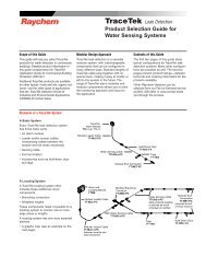
<strong>ElectroMelt</strong> <strong>System</strong><strong>Design</strong> <strong>Guide</strong>Supplemental <strong>Design</strong>InformationUsing Figures 1–6 on page 18Once you have determined the correct curve to use for your application, turn to the correctfigure for that curve and take the following steps:1. Draw a horizontal line across the figure at the heating-cable spacing you plan to usein the design.2. Draw vertical lines from the points where the segmented snow melting performancecurves intersect your horizontal heating-cable-spacing line.3. From the intersection of the left vertical line with the percentage axis read the percentageof all snowfall conditions for which the pavement will be completely clear.The distance between the left and right vertical lines is the additional percentage of allsnowfall conditions for which the pavement may have a light snow cover. The distance, ifany, from the right line to the end of the percentage axis is the percentage of snowfallconditions for which snow may actually accumulate while the system is in operation. Ifincreased snow-melting performance is required, reduce the heating cable spacing.ExampleTo determine the snow-melting performance you should specify for <strong>ElectroMelt</strong> heatingcable installed on 10-inch centers in Chicago, Illinois, find the figure number for Chicagoin Table 4. The table refers you to Figure 1.Using Figure 1, you see that the intersection of the 10-inch-spacing line with the“Surface Completely Clear” curve occurs at approximately 88%, and the intersectionwith the “Some Accumulation Possible” curve occurs at 0%.These percentages indicate that the system with 10-inch spacing will keep the surfacecompletely clear for 88% of all snowfall conditions occurring in Chicago, and will allowno accumulation.For the remaining 12% of conditions, the surface may have a light covering of snow, butthe system will be able to melt snow at the same rate at which it falls (no accumulation).17
<strong>ElectroMelt</strong> <strong>System</strong><strong>Design</strong> <strong>Guide</strong>Supplemental <strong>Design</strong>InformationSnow-Melting Performance CurvesFigure 1.Figure 2.66Heating Cable Spacing (inches)81012Surface Completely ClearLightCoverPossible81012Surface Completely ClearLightCoverPossibleSnow AccumulatesSnow Accumulates0 25 50 75 100Cumulative Snowfall Hours (%)0 25 50 75 10Cumulative Snowfall Hours (%)Figure 3.Figure 4.66Heating Cable Spacing (inches)81012Surface Completely ClearLightCoverPossible81012Surface Completely ClearLightCoverPossibleSnow AccumulatesSnow Accumulates0 25 50 75 100Cumulative Snowfall Hours (%)0 25 50 75 10Cumulative Snowfall Hours (%)Figure 5.Figure 6.66Heating Cable Spacing (inches)81012Surface Completely ClearLightCoverPossible81012Surface Completely ClearLightCoverPossibleSnow AccumulatesSnow Accumulates0 25 50 75 100Cumulative Snowfall Hours (%)0 25 50 75 10Cumulative Snowfall Hours (%)18
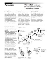
<strong>ElectroMelt</strong> <strong>System</strong><strong>Design</strong> <strong>Guide</strong>Supplemental <strong>Design</strong>InformationElectrical Performance RequirementsElectrical <strong>Design</strong>The <strong>ElectroMelt</strong> EM2-XR self-regulating heating cable varies its power output at everypoint along its length in response to the surface temperature or sheath temperature ofthe heating cable. When the concrete in contact with the surface of the heater is cool,the cable is cool and the resistance of the specially blended polymer core is low, resultingin high power output. As the pavement warms, the heating cable core warms and thecore resistance rises, resulting in lower power output. A graph of the relationshipbetween sheath temperature and power output of the EM2-XR heating cable appearsbelow.Maximum Startup PowerPower (watts/foot)Steady-State Operation0°Heating Cable Sheath Temperature (°F)275°During normal operation, the heating-cable output varies between the points marked“Maximum Startup Power” and “Steady-State Operation.” The heating-cable operatingtemperature varies with the concrete temperature and weather conditions, but is usuallyabout 60°F warmer than the concrete surface. On a hot summer day, the concrete in contactwith the heating cable could reach 150°F.Startup TemperatureThe maximum length of heating cable allowed on a given size circuit breaker is determinedprimarily by the current drawn by the heating cable during low-temperature (highpower)startup conditions. The maximum circuit length data given in Table 1 on page 11is based on starting the heating cable when the concrete pavement is at 0°F. A maximumlength circuit started at 0°F will result in branch circuit loading of less than 80 percent ofthe circuit breaker rating within 10 minutes.Transformer SizingTransformers should be sized to handle the startup load of the heating cable indefinitely.To determine the current load of each circuit, refer to the circuit breaker rating tables onpage 11. The actual current per foot of heating cable and the transformer size are calculatedas follows:Currentper foot= 0.8 xCircuit breaker ratingMaximum allowed length of heating cable at design voltageTransformer= Current x Total heating xHeating cablesize per foot cable length operating voltageVoltage DropCalculate the branch circuit voltage drop based on the current as computed above. Notethat the maximum size branch circuit conductor that can be terminated in the EMK-XPpower connection kit is 4 AWG.19
<strong>ElectroMelt</strong> <strong>System</strong><strong>Design</strong> <strong>Guide</strong>Supplemental <strong>Design</strong>InformationExampleAn application at a parking garage requires four heating cable circuits 275 feet long. Theheating cable is to be powered at 277 Vac.Circuit Breaker SizingFrom Table 1 on page 11, up to 300 feet of heating cable may be connected to a single50-amp branch circuit breaker.Transformer SizingThe branch circuit current after startup at 0°F is calculated as follows:CurrentTransformer size= 80% x 50 amp/300 ft= 0.13 amp/ft= 0.13 amp/ft x 275 ft/circuit x 4 circuits x 277 Vac= 39,600 watts= 39.6 kilowattsTo have a copy of the <strong>ElectroMelt</strong> Product Data Sheets automatically faxed to you,use Raychem’s Fax On Demand Service.Dial (800) 329-4494 and plug in Document ID Number 20110.20
<strong>ElectroMelt</strong> <strong>System</strong><strong>Design</strong> <strong>Guide</strong>Project Submittal DataSubmittal Data FormProject DataProject or area nameSubmitted byReferenceDate<strong>Design</strong> DataSite locationMinimum ambient temperatureAverage wind speedHeating cable spacingDescription of performance requirementsPavement DataPavement materialPavement thicknessHeating cable depthType of reinforcementDescription of area to be heatedIs pavement placed on grade?(if not, please describe)Product DataHeating cable modelHeating cable manufacturerProduct approvalsPower connection kit modelSplice kit modelExpansion joint kit modelElectrical DataHeating cable operating voltageBranch circuit overcurrent protection device and ratingHeating cable junction box descriptionControl system descriptionTotal electrical load (kW)21
22<strong>ElectroMelt</strong> <strong>System</strong><strong>Design</strong> <strong>Guide</strong>
<strong>ElectroMelt</strong> <strong>System</strong><strong>Design</strong> <strong>Guide</strong>CondensedSpecification <strong>Guide</strong>This is the product portion of a specification for the <strong>ElectroMelt</strong> <strong>System</strong>. For a completespecification that includes installation and testing recommendations, contact yourRaychem representative.PART 1 – GENERALFurnish and install a UL Listed and CSA Certified snow-melting system complete withheating cable, termination components, junction boxes, contactors, and controls.PART 2 – PRODUCTS2.1 The heating cable and termination components shall be UL Listed as De-icing andSnow-melting Equipment and CSA Certified as <strong>Design</strong>ation 1B, 2B.2.2 The heating cable shall consist of two 14-gauge nickel-coated-copper bus wiresembedded in parallel in a self-regulating polymer core. Power output shall vary inresponse to temperature all along its length, allowing the heating cable to becrossed over itself without overheating, to be cut to length in the field, and to haveno heater-to-cold-lead connections buried in the pavement. The heating cable shallbe covered by a crosslinked dielectric jacket and protected by a tinned-copper braidand a 70-mil-thick modified polyolefin outer jacket.2.3 The heating cable shall be of parallel circuit construction to allow the cable to bespliced if it is inadvertently cut during or after construction, and to be powered fromboth ends if it becomes advantageous to divide a circuit in two.2.4 The heating cable shall operate on (select: 208, 220, 240, or 277) volts without theuse of transformers.2.5 The heating cable shall be <strong>ElectroMelt</strong> EM2-XR as manufactured by RaychemCorporation.2.6 The system shall be controlled by (select: a switch, an ambient sensing thermostat, oran automatic snow controller) through an appropriate contactor.2.7 The heating cable power connection and end seal terminations shall be made in an<strong>ElectroMelt</strong> EMK-XJB junction box.2.8 Each circuit shall be protected by a 30-mA ground-fault protection device.PART 3 – INSTALLATION3.1 The heating cable shall be installed according to the manufacturer’s recommendations,the instructions supplied with the heating cable and components, and theinstructions in the <strong>ElectroMelt</strong> Installation and Operation Manual (H53392).3.2 The heating cable shall be installed only in concrete pavement designed for longtermstructural integrity. The pavement shall be reinforced with rebar or wire meshand the reinforcing supported such that the location of the reinforcing and theattached heating cable is not disturbed during the concrete placement. The rebarshall be placed at the heating-cable depth whenever possible.3.3 The heating cable shall be protected from where it leaves the pavement to the junctionbox by installing the cable in 1-inch rigid metal conduit. Use one conduit foreach heating cable.3.4 The power connection and end seal junction box shall be mounted above grade. Thejunction box shall be installed so that water can not enter it.3.5 Heating-cable repairs and splices shall be made using a splice kit provided by themanufacturer and specifically approved for the purpose. They shall pass the Meggertest after installation.PART 4 – TESTINGThe heating cable shall be tested for insulation resistance with a 2500-Vdc Meggerafter installation, during the concrete pour, and annually thereafter according to themanufacturer’s recommendations and following the instructions provided in the<strong>ElectroMelt</strong> Installation and Operation Manual (H53392).23
24<strong>ElectroMelt</strong> <strong>System</strong><strong>Design</strong> <strong>Guide</strong>
<strong>ElectroMelt</strong> <strong>System</strong><strong>Design</strong> <strong>Guide</strong>Appendix AWarranty; Suitability(a) Raychem warrants products delivered hereunder against faulty workmanship and useof defective materials for a period of eighteen (18) months from the date of installationor twenty-four (24) months from the date of shipment, whichever is sooner. When thecontract calls for systems design, drawings, technical advice, services, or instructions(collectively “Services”) by Raychem, in connection with the products, Raychem furtherwarrants for the above stated warranty period solely that such Services will be undertakenin accordance with Raychem’s reasonable technical judgment based on Raychem’sunderstanding of the pertinent technical data as of the date of performance of suchServices. The foregoing warranty with respect to products shall not be enlarged oraffected by, and (except as expressly provided herein) no obligation or liability shall ariseor grow out of, Raychem’s rendering Services in connection with the products. Suchwarranty is the only warranty made by Raychem and it can be amended only by a writteninstrument signed by a duly authorized officer of Raychem. If the products furnished byRaychem hereunder are determined to contain a deficiency, Buyer’s exclusive remedyshall be to have Raychem repair such products or supply replacement products or creditBuyer’s account for such products and accept their return, whichever Raychem mayelect in its sole discretion. Notwithstanding the foregoing sentence, in no circumstancesshall Raychem have any liability or obligation with respect to expenses, liabilities, orlosses associated with the installation or removal of any products or the installation ofreplacement products or for any inspection, testing, or redesign occasioned by any deficiencyor by the repair or replacement of products. Raychem’s obligations are subject tothe further condition that Raychem shall have no liability whatsoever for any deficiencyunless (i) Raychem is notified in writing promptly (and in no event later than 30 days)after discovery by Buyer of the alleged deficiency, which notice shall include a detailedexplanation of the alleged deficiency, (ii) the products containing the alleged deficiencyare promptly returned to Raychem, F.O.B. Raychem’s plant, and (iii) Raychem’s examinationof such products discloses to Raychem’s satisfaction that such alleged deficiencyactually exists and occurred in the course of proper and normal use and was not causedby accident, misuse, neglect, alteration or improper installation, repair, or testing. If anyproducts so prove to contain a deficiency and Raychem elects to repair or replace them,Raychem shall have a reasonable time to make such repair or replacement.THE FOREGOING WARRANTY IS IN LIEU OF ALL OTHER WARRANTIES, EXPRESS ORIMPLIED, INCLUDING WITHOUT LIMITATION ANY IMPLIED WARRANTY OF MER-CHANTABILITY, FITNESS FOR A PARTICULAR PURPOSE, OR NONINFRINGEMENT, ANDOF ANY OTHER OBLIGATION ON THE PART OF RAYCHEM.(b) It shall be the responsibility of the Buyer to determine, on the basis of the most currentwritten technical data, the suitability of the products and of any systems design ordrawings for the intended use and their compliance with applicable laws, regulations,codes, and standards and the Buyer assumes all risks pertaining thereto.25
RLISTED877ZDe-Icing and Snow-Melting Equipment®DESIG. 1B, 2B<strong>ElectroMelt</strong>,TraceGuard, and ShrinkWrap are trademarks of Raychem Corporation.Important: All information, including illustrations, is believed to be reliable. Users, however,should independently evaluate the suitability of each product for their application. Raychemmakes no warranties as to the accuracy or completeness of the information, and disclaimsany liability regarding its use. Raychem’s only obligations are those in the RaychemStandard Terms and Conditions of Sale for this product, and in no case will Raychem or itsdistributors be liable for any incidental, indirect, or consequential damages arising from thesale, resale, use, or misuse of the product. Specifications are subject to change withoutnotice. In addition, Raychem reserves the right to make changes—without notification toBuyer—to processing or materials that do not affect compliance with any applicable specification.Raychem Corporation North America South America300 Constitution Drive Raychem Canada Limited Raychem S.A.I.C.Menlo Park, CA 94025-1164 Toronto, Ontario Carlos Pellegrini 1163, Piso 7USA Canada 1009 Capital Federal, Buenos AiresTel (800) 545-6258 Tel (800) 545-6258 ArgentinaFax (650) 474-7515 Fax (650) 361-5579 Tel (54)11/4394-5150Fax-on-Demand (800) 329-4494 Fax (54)11/4326-9985info@raychemhts.comwww.raychemhts.comISO 9001© 1989,1994, 1996, 1998, 2000 Raychem Corporation Printed in USA (10M) (P3938) H53393 5/00