mercury sp - Ferroli
mercury sp - Ferroli
mercury sp - Ferroli
- No tags were found...

Create successful ePaper yourself
Turn your PDF publications into a flip-book with our unique Google optimized e-Paper software.
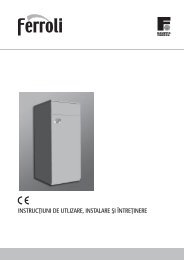
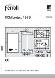
Technical characteristicsPurging of air from the water batteryIn filling the installation with water, <strong>sp</strong>ecial attention must be given to the purging of air from the batteries. For this purpose, there is an accessto the air drain on the upper part of the side of the unit. The purging is manual.Main BateryHot water BateryMod. 05 - 07 - 11 Mod. 13 - 17 - 21 - 23BLEEDERBLEEDERBLEEDER70
FeaturesCooling featuresMODEL0507111317192123Inlet / outletAir temperature at the inlet (B.D.) with Hr = 50%temperature22ºC 24ºC 26ºC 27ºC 28ºCof water ºCkWf kWs kWf kWs kWf kWs kWf kWs kWf kWs5/10 4.02 3.12 5.03 3.61 5.84 4.09 6.18 4.54 6.79 4.607/12 3.33 2.64 3.84 3.17 4.81 3.65 5.04 4.06 5.80 4.119/14 2.89 2.34 3.38 2.81 4.10 3.36 4.36 3.81 5.42 3.955/10 6.36 4.54 7.87 5.24 9.11 5.90 9.64 6.56 10.54 6.657/12 5.19 3.85 6.08 4.60 7.55 5.28 7.91 5.84 9.02 5.949/14 4.53 3.44 5.27 4.11 6.50 5.00 6.92 5.31 8.48 5.715/10 7.60 5.23 9.09 5.99 10.27 6.70 10.87 7.44 11.69 7.497/12 5.80 4.49 7.27 5.29 8.69 6.03 9.11 6.72 10.15 6.739/14 5.12 4.05 5.89 4.79 7.75 5.16 8.26 5.48 9.75 6.485/10 8.23 5.40 10.29 6.24 11.95 7.04 12.64 7.83 13.88 7.947/12 6.83 4.59 7.88 5.47 9.85 6.31 10.33 7.61 11.84 7.109/14 5.97 4.07 6.94 4.87 8.39 5.71 8.94 6.39 11.07 6.815/10 10.76 7.62 13.32 8.78 15.37 9.89 16.26 10.99 17.79 11.137/12 8.79 6.47 10.27 7.71 11.98 8.86 13.33 9.78 15.22 9.959/14 7.69 5.78 8.92 6.89 10.94 8.07 11.65 9.21 14.30 9.575/10 12.85 9.55 13.58 11.06 19.15 12.52 20.27 13.92 22.41 14.147/12 11.03 8.03 12.28 9.70 15.63 11.20 16.38 12.30 19.00 12.639/14 9.61 7.15 11.24 8.59 13.09 9.73 13.94 10.57 17.59 12.105/10 17.05 12.90 20.91 14.84 23.96 16.69 25.36 18.54 27.58 18.737/12 13.61 10.98 16.32 13.06 19.98 14.97 20.94 15.72 23.73 16.789/14 12.37 10.19 13.83 11.71 17.41 13.29 18.53 14.96 22.48 16.145/10 19.14 13.25 23.12 15.21 26.22 17.05 27.75 18.94 29.97 19.107/12 14.88 11.37 18.30 13.42 22.06 15.34 23.12 17.16 25.94 17.139/14 13.06 10.22 15.04 12.11 19.51 14.27 20.78 15.61 24.78 16.51kWf: Total cooling capacity total in kWkWs: Sensitive cooling capacity sensible en kWValues in reference to nominal air flow rate, maximum <strong>sp</strong>eed72
FeaturesHeating featuresMODEL0507111317192123Inlet / outletAir Temperature at the inlet (B.D.) with Hr = 50%temperature10ºC 16ºC 19ºC 20ºC 21ºCof water ºCkWt kWt kWt kWt kWt80 / 70 15.79 15.15 14.38 14.11 13.8670 / 60 14.38 12.48 11.72 11.45 11.2055 / 45 9.99 8.42 7.63 7.38 7.1145 / 40 8.18 6.63 5.85 5.60 5.3380 / 70 24.23 22.00 20.88 20.51 20.1370 / 60 20.40 18.16 17.04 16.65 16.2855 / 45 14.54 12.29 11.16 10.78 10.3945 / 40 11.88 9.64 8.53 8.16 7.7880 / 70 27.56 25.04 23.79 23.38 22.9670 / 60 23.28 20.77 19.52 19.10 18.6855 / 45 16.77 14.24 12.96 12.53 12.1145 / 40 13.57 11.06 9.81 9.38 8.9780 / 70 31.58 28.67 27.20 26.71 26.2370 / 60 26.52 23.64 22.17 21.68 21.2055 / 45 18.81 15.96 14.47 13.97 13.4845 / 40 15.48 12.55 11.09 10.60 10.1180 / 70 40.28 36.57 34.71 34.10 33.4770 / 60 33.92 30.18 28.33 27.70 27.0855 / 45 24.22 20.47 18.57 17.94 17.3145 / 40 19.77 16.05 14.20 13.57 12.9480 / 70 51.47 46.69 44.30 43.51 42.7070 / 60 43.24 38.45 36.05 35.24 34.4455 / 45 30.70 25.85 23.43 22.62 21.8245 / 40 25.19 20.41 18.02 17.22 16.4380 / 70 65.16 59.19 56.19 55.21 54.2070 / 60 54.92 48.93 45.93 44.93 43.9455 / 45 39.32 33.27 30.22 29.21 28.1945 / 40 32.00 27.09 23.03 22.04 21.0280 / 70 70.53 64.10 60.88 59.80 58.7470 / 60 59.54 53.09 49.85 48.74 47.6955 / 45 42.78 36.25 32.97 31.87 30.7845 / 40 34.69 28.26 25.33 23.95 22.90kWt: Thermal capacityValues in reference to nominal air flow rate, maximum <strong>sp</strong>eed73
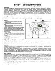
FeaturesHead loss water side main batteryTo calculate the loss of charge of the standard battery supplied with the Mercury-SP unit, the water flow volume must first be calculated; inorder to do this we shall use the following curves, which, depending on the capacity of the unit and the desired thermal difference, we obtainthe water flow volume.43.5T= 5°C3T= 10°CWater flow rate (m 3 /h)2.521.5T= 15°CT= 20°C10.500 10 2030 40 50Power (kW)Entering this flow volume into the following diagrams, we obtain the loss of charge of the main battery, working with a mean water temperatureof 10ºC.40111330Head loss (kPa)201005001.000 1.500 2.000Water flow rate (l/h)74
Features4017 19212330Head loss (kPa)201001.5002.000 2.500 3.000Water flow rate (l/h)3.500 4.000For a water temperature other than 10ºC, the loss of charge can be calculated with the following formula:ΔPC= ΔP cnomx KWhere:DPcnom: is the head loss calculated in the diagramΔPc: is the head loss under conditions different from the previous onesK: is the value obtained on the following tables.K CORRECTION FACTORMean water temperature 5 10 15 20 50 60 70K correction factor 1.05 1.00 0.97 0.95 0.8 0.75 0.7175
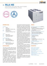
Ventilation curvesVentilation curve Mod. 05120Available static pressure (Pa)10080604020V.mín.V.med.V.máx.600 800 1000 1200Air flow rate (m 3 /h)Ventilation curve Mod. 07120Available static pressure (Pa)10080604020V.mín.V.med.V.máx.700 1000Aire flow rate (m 3 /h)1500Ventilation curve Mod. 11120Available static pressure (Pa)10080604020V.mín.V.med.V.máx.600 1000 1500 2000Air flow rate (m 3 /h)76
Ventilation curvesVentilation curve Mod. 13120Available static pressure (Pa)10080604020V.mín.V.med.V.máx.600 1000 1500 2000Air flow rate (m 3 /h)Ventilation curve Mod. 17120Available static pressure (Pa)10080604020V.mín.V.med.V.máx.1000 2000Aire flow rate (m 3 /h)Ventilation curve Mod. 19140120Available static pressure (Pa)10080604020V.mín.V.med.V.máx.1000 1500 20002500Air flow rate (m 3 /h)77
Ventilation curvesVentilation curve Mod. 21140120Available static pressure (Pa)10080604020V.mín.V.med.V.máx.Ventilation curve Mod. 231402500 3000 35004000Air flow rate (m 3 /h)120Available static pressure (Pa)10080604020V.mín.V.med.V.máx.2500 3000 35004000Air flow rate (m 3 /h)78
AccessoriesThe accessories available in this product range are:-------Cross valve for the main batteryCross valve for the hot water batteryCondensate collection tray for the cross valveHot water batteryFan relays kitMinimun temperature thermostatWall switch------Wall base controlComplete controlIntake plenumIntake grilleDelivery plenumDelivery grilleTable of accesoriesDescription Model 05 07 11 13 17 19 21 23SRW F1•SRW F2 • •Hot water batterySRW F3 • •SRW F4 • •SRW F5•Cross valve for the main battery V3V • • • • • • • •Cross valve for the hot water battery V3VP • • • • • • • •Condensate collection tray for the cross valve BV • • • • • • • •Fan relays kit KR • • • • • • • •Delivery round plenumIntake plenumDelivery grilleIntake grillePB F1•PB F2 • •PB F3 • •PB F4 • •PB F5PA F1•PA F2 • •PA F3 • •PA F4 • •PA F5GM F1•GM F2 • •GM F3 • •GM F4 • •GM F5GA F1•GA F1 • •GA F1 • •GA F1 • •GA F1••••79
AccessoriesHot waterbatteryDeliveryplenumDeliverygrilleIntakeplenumFan relayskitCross valve forthe hot waterbatteryIntake grilleCondensate collectiontray for thecross valveCross valve forthe main batteryCross valve kit for the main batteryIts purpose is to supply the main battery of the MERCURY-SP unit with cold or hot water, or make a by-pass.It is composed of the body of the valve, the actuator, and a set of nuts with sealing gaskets and flexible copper sleeves. To collect thecondensation produced on its surface using cold water, the condensate tray must be used.80
AccessoriesCross valve kit for the hot water batteryIts purpose is to supply the hot water battery of the MERCURY-SP unit with water from a boiler or make a by-pass.It is composed of the body of the valve, the actuator, and a set of nuts with sealing gaskets and copper sleeves.The size of the valve is 3/4” for the entire range.Condensate collection trayBuilt of galvanized sheet metal, with outer treatment of powder-coated polyester paint, its purpose is to collect the condensed water from thehydraulic connections of the MERCURY-SP and of the cross valve of the main battery, when the unit is in cooling mode.During the installation process, the drop of the drain pipe must be controlled.Kit fan relaysIt lets to use the standarized <strong>Ferroli</strong> fancoil controllers (see electrical diagrams in this manual).The relays are supplied assembled on a metal plate with a cover made of metallic galvanized sheet, including the corre<strong>sp</strong>onding wires andelectrical connections, easy to replace by the standard electrical box originally supplied with the unit.See the electrical diagram included in this manual, in order to connect it.81
AccessoriesMinimun temperature thermostatThis accessory can be used with the fan switchboard controller to inhibit fan operation in heating mode if the inlet water temperature fails toreach a minimum value.See the electrical diagram included in this manual, in order to connect it.Faston 6.3 x 0.8Intake plenumMade of galvanized metal sheet, it’s used to take directly the air, when it’s not used any intake duct. It can be used with the intake grille.Model A B C D Uds.05 588 301 250 240 mm07/11/13/17 993 301 250 240 mm19/21/23 1280 301 250 300 mmABDCIntake grilleMade of anodized aluminium, includes an air filter that can be easily removed.Model A B Uds.05 450 200 mm07/11/13/17 850 200 mm19/21/23 1135 200 mmABB + 50A + 5082
AccessoriesCircular delivery plenumMade of galvanized plate, it’s used to direct air to the room by means of tube ducts.It has round plastic flanges, and can be easily cut in order to be used with one or another connection diameter.BModel A B Uds.05 450 200 mm07/11/13/17 850 200 mm19/21/23 1135 200 mmCADelivery grilleMade of anodized aluminium, it lets to direct manually the air direction both horizontally or vertically by means of the position of thelouvers.Modelo A B Uds.05 564 253 mm07/11 931 245 mm13/17 1017 275 mm19/21/23 1215 315 mmBA + 50B + 50AHot water batteryIts purpose is to heat, using water from a boiler (four-pipe unit).The standard battery will be used to cool (two pipes), and the supplementary battery of the water battery (the other two pipes) to heat thebuilding.The water battery is supplied in a plenum, which is screwed directly on the discharge nozzle of the unit.The battery is made with expanded copper tubes and aluminium fins.The batter is equipped with an air drainHydraulic connections hot water batteryModels 05 - 07 - 11Models 13 - 17 - 19 - 21 - 235045251083
AccessoriesDimensions6301822705027Mod. 59901822705026Mod. 7 - 1111353032934711Mod. 13 - 171330342331469Mod. 19 - 21 - 23Technical <strong>sp</strong>ecifications hot water batteryMODEL Uds. 05 07 11 13 17 19 21 23Thermal capacity (1) Vel. med. W 5465 7854 9163 11950 12807 21200 23711 24470Vel. máx. W 5752 8374 9800 13451 14738 22599 24425 25373Vel. mín W 5168 6519 7175 10163 10506 19500 21986 22443Head loss air side (2) Pa 25 22 26 20 21 22 31 34Water flow rate (1) l/h 490 713 828 1141 1253 1840 2081 2156Head loss water side (1) kPa 15 11 13 10 11 6 8 9Nº of rows in battery nº 2 2 2 2 2 2 2 2Conditions:(1) Heating: Ambient temperature 20ºC; Water intake temperature 70ºC, thermal difference 10ºC. Fan at maximum <strong>sp</strong>eed.(2) With the fan at maximum <strong>sp</strong>eed84
AccessoriesWith the first diagram the flow volume is calculated according to the cooling capacity and the thermal difference.43.53T= 5°C2.5Water flow rate (m 3 /h)21.510.5T= 10°CT= 15°CT= 20°C02 3 4 5 6 7 8 9 10 11 12 13 14 15 16 17 18 19 20 21 22Power (kW)With the second diagram entering with the water flow volume, and depending on the model, the loss of charge water side is calculated.4005 07-11 13-17 19-21-2330Head loss (kPa)20100 500 1.000 1.500 2.000 2.500Water flow rate (l/h)85
AccessoriesRemote controlsThree types of wall controls are offered:- Switch CMR-F- Thermostat TAR-F- Complete thermostat TER-FFunctionsFor a more rapid selection of the control model between the three types, the various functions available are listed as follows. Said functionsare described in the following pages.FUNCTIONS SWITCH THERMOSTAT COMPLETE THERMOSTATGeneral control of unitGeneral ON-OFF • • •Temperature controlThermostatic temperature control • •Modification set point with Economy key•Ventilation controlManual fan <strong>sp</strong>eed selection • • •Automatic fan <strong>sp</strong>eed selection•Season operation control VER / INVManual operation selection VER / INV on the control • •Automatic operation selection VER/INV on the control • •Remote operation selection VER/INV•Management valve accessoriesCross valve main battery • •Cross valve auxiliary battery•Configurable functions in installation phaseThermostatic management fan ON / OFF / Continuous • •Correction reading probe • •Unit - installation configuration with 2 pipes•Unit - installation configuration with 4 pipes (*)•Resistance management • • •Definition dead zone•Integration with possible accessoriesBimetal minimum temperature probe•(*) Standar unit + hot water battery86
AccessoriesSwitch description (CMR-F)12Switch (CMR-F)1.2.Selector 1 in position 0 indicates control off; switching to the sun symbol, heating is activated,while switching to the snow symbol, cooling is activated.Selector 2 selects the minimum, medium or maximum fan <strong>sp</strong>eed.In case of using CMR-F switch with units for hot water, it is recommended to use the minimum temperaturethermostat TC-F (optional).Base Thermostat description (TAR-F)12354Base Thermostat (TAR-F)1.2.3.4.5.ON / OFF cursorSeason selector; Switching to the sun symbol, heating is activated while the snow symbol activatescooling. If auto is selected, the control selects the mode of operation automatically depending onthe ambient temperature.With selector 3, the minimum, medium, or maximum fan <strong>sp</strong>eed is selected.With knob 4, the desired temperatures are defined. The temperature corre<strong>sp</strong>onding to position 0is 20ºC in heating and25ºC in cooling.The red LED lights up when the control is working with the thermostat.Complete Thermostat description (TER-F)12367Main dimensions of control panel54Complete Thermostat (TER-F)1.2.3.4.5.6.ON / OFF cursorSeason selector; Switching to the sun symbol, heating is activated while the snow symbol activatescooling. If auto is selected, the control selects the mode of operation automatically depending onthe ambient temperature.With selector 3, the minimum, medium, or maximum fan <strong>sp</strong>eed is selected. In automatic, thecontrol automatically selects the suitable <strong>sp</strong>eed.With knob 4, the desired temperatures are defined. The temperature corre<strong>sp</strong>onding to position 0is 20ºC in heating and25ºC in cooling.The red LED lights up when the control is working with the thermostat.The Economy key allows the winter and summer set points to be varied. Pressing the key, thegreen LED lights up (7) and the ventilation changes to the minimum <strong>sp</strong>eed.temperature of position 0 is modified to 17ºC in heating and 28ºC in cooling.14530.75 83.530.75Simultaneously, the3342783687
AccessoriesInformation and technical <strong>sp</strong>ecifications of controlELECTRICAL CHARACTERISTICSPower supply voltage 230V ± 10%Power supply frequency50 HzMaximum capacity absorbed -Degree of protection Lower than IP 40Ambient operating temperature 0 ÷ 50ºCNon-condensing ambient humidity 10 ÷ 90%Storage temperature -20 ÷ 85ºCNon-condensing storage humidity 10 ÷ 90%Maximum current cross valve outlet terminals 0.5AMaximum current fan outlet terminals1APROBESAir probe NTC 10k -25ºC - precision err < 1ºC between +5ºC and 50ºCMounted on air intake - Length 600mmAir probe NTC 10k -25ºC - precision err < 1ºC between +5ºC and 50ºCMounted in contact with the water battery - Length 1800mmInstallation optionsIn the installation the base and complete controls can be configured according to the option:Configuration of type of machine: This operation, with some dip switches, allows the selection of the control application type.TYPE OF APPLICATION BASE THERMOSTAT COMPLET THERMOSTAT4 Pipe machine •2 Pipe machine • •Thermostat regulation on the valve • •Thermostat regulation on the fan • •Dead zone 1 (2ºC) • •Dead zone 2 (5ºC) • •Remote activation summer/winter function•Thermostatic regulation of the fanIn this case, the cross valve is not used (the hot or cold water passes freely in the battery), and the regulation of the thermostat is carried outby turning the fan on or off. This regulation is associated with both the heating and the cooling mode. To prevent errors in the readings of theambient probe, the PERIODIC VENTILATION function was provided, activated both in cool and in heat.Evolution of temperatureONFanOFFHeat mode operationONFanOFFCool mode operation88
AccessoriesThermostatic regulation of the cross valveIn this case, the management of the fans differs depending on operation in heating or cooling, as explained below:- Cooling: Thermostatic regulation opens / closes the valve according to demand, while the fan is always active, even when thethermostatic regulation has reached the temperature(min, med, or max position ) or starts and stops according to demand (autoposition) and periodic ventilation.- Heating: The thermostatic regulation opens/closes the valve while the fan is controlling the HOT START and PERIODIC VENTILATIONfunctions with the corre<strong>sp</strong>onding delay times.Evolution of temperatureONValveOFFHeat mode OperationONFanOFFONValveOFFCool mode OperationFan ONcontinuoOFFFanautoONOFFHeating/ cooling with thermostatic regulation in the cross valveThe management of the cross valve carries out an ON / OFF control with indicator of valve closure on reaching the set point, depending on thehysteresis cycles of the heating / cooling diagrams. The valves to be used are of the normally closed type, with electrothermic actuators withopening/closing times of approximately three minutes.The fan is controlled by timer as explained in the paragraph VENTILATION CONTROL, to constantly capture the ambient temperature.Position of the water probeWaterTemp.Water probe position89
AccessoriesHysteresis of thermostat regulation modesFor the unit controls, the hysteresis is 1ºC, while for wall controls, it is 0.6ºC.Heat modeWork hysteresisCool modeWork hysteresistemperaturetemperatureVentilation controlIn the base and complete thermostat, the management of the ventilation depends on the mode of operation selected (cool, heat):- Fan <strong>sp</strong>eedIf the fan is activated, its <strong>sp</strong>eed can be:» Defined manually by the user» Defined automatically, if the fan switch is in auto position (only advanced thermostat).- Thermostatic regulation of the ventilationEIn this case the fan will activate and de-activate as described on page 20- Thermostatic regulation in the valveEIn the case that thermostatic regulation is configured in the valve, the fan is automatically programmed with modes of continuousoperation in cooling (fans always turned on), while in heating (as the probe at the entrance of the valve cannot control the intake ofcold air) timing of the fan is provided:» Fan ON after 180 seconds gives the order to close the valve.» Fan OFF after 180 seconds gives the order to close the valve.The hot start function is always active (in heating) for water temperatures lower than 39ºC.- Automatic ventilationFan <strong>sp</strong>eed is regulated on the basis of the variation of the ambient temperature and the temperature programmed by the set point.Said variation depends on the hysteresis programmed in the regulator which is:» 0.6ºC for the wall controls» 1ºC for the unit controlsIn the following figure, the variation values of the controller on the machine are explained. . To fit the diagrams to the wall model, the variationvalues must be substituted in the following manner:- Cooling mode: the values +1, +2, +3 change to +0.6, +1.2, +1.8- Heating mode: the values -1, -2, -3 change to -0.6, -1.2, -1.8Fan SpeedFan Speedset pointEnviroment Temp.Cool ModeHeat Modeset pointEnviroment Temp.Note: The set point stated on the axis of abscissas of the diagrams refers to the value programmed in the potentiometer by the user.90
AccessoriesPeriodic ventilationIn the case in which the control is imbedded in the machine, when the fan is turned off due to having reaching thermostatic regulation, ON /OFF cycles of the fan shall be carried out, to allow the air probe to capture the actual ambient temperature. Said function is activated both inthe heating and cooling mode.HOT START functionThis consists of the pre-heating of the battery prior to starting the fan. This function is only active in heating mode and can be done in twoways:- Ventilation time delay: for controls with thermostatic regulation in the cross valve there is a fixed delay timing of 180 seconds betweenthe activation of the heat regulator and the activation of the ventilation, to allow the valve to open completely. After 180 seconds the fanwill start up when the water probe reaches a temperature greater than or equal to 39.5ºC. This function does not exist in the controlswith thermostatic regulation in the fan.- Ventilation start-up: The fan starts up when the water temperature is greater than 39.5ºC; this function exists in both the controls asthermostatic regulation in the valve and in the fan.Valve / Fan ON38.5°C39°C39.5°CWater temperature ºCHysteresis diagram of the thermostatic regulation (valve or fan, depending on the type of controller).Post-ventilationAfter disconnection by thermostat of the electric elements, ventilation continues in operation for 90 seconds, in order to cool the elements.91
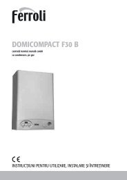
Electrical diagramsCV7 8SBR31413121110LN853535353SWITCH CMR-FMERCURY - SPVM1V3V2V1CTTROAZNEV3V2V1CNLMINMEDMAXCOM7 87 8R2R1OPTIONALTC76541 2 3AutoMERCURY SPRelays kitSWITCH CMR-FLTC = Minumun temperature thermostatIG = Circuit braker (to be put in by installer)NIGSB5353Observation: relays kit is neccessaryBASE THERMOSTAT TAR-FMERCURY - SPCVVM1V3V2V1CTTROAZNEV3V2V1CNLMINMEDMAXCOM7 87 87 8R3R2R1OPTIONALVF1413121110LN14131210761 2 3-4-6-200IAuto246MERCURY SPRelays kitBASE THERMOSTAT TAR-FSB = Inlet water battery probeVF = Cold water battery valveIG = Circuit braker (to be put in by installer)LNObservation: relays kit is neccessaryIG92
Electrical diagrams7 8141312L1413121075SBCV3ROAZ5353COMPLETE THERMOSTAT TER-FMERCURY - SPVM1V3V2V1CTTNEV3V2V1CNLMINMEDMAXCOM7 87 8R3R2R1OPTIONALVFVC1110N1161 2 3-4-6-200IAutoAuto246MERCURY SPRelays KitCOMPLETE THERMOSTAT TER-FSB = Inlet water battery probeVF = Cold water battery valveVC = Hot water battery valveIG = Circuit braker (to be put in by installer)Observation: relays kit is neccessaryLNIG93
Férroli E<strong>sp</strong>sña S.L.U. - 09001 Burgos (Burgos) E<strong>sp</strong>aña - C/. Alcalde Martín Cobos s/nTlf: 947 483250 - Fax: 947 474195 - www.ferroli.esCod: A73018551 15/05/2009