Create successful ePaper yourself
Turn your PDF publications into a flip-book with our unique Google optimized e-Paper software.
<strong>POP</strong>-<strong>BOT</strong> : The Arduino Compatible Mobile Robot kit • 1Activity manualversion 1.0 Standard(c) Innovative Experiment Co. ,Ltd.www.inexglobal.com
2 l <strong>POP</strong>-<strong>BOT</strong> : The Arduino Compatible Mobile Robot kitCerdits<strong>POP</strong>-168 Module, RBX-168 Robot controller board are trademarks of Innovative ExperimentCo., Ltd.<strong>POP</strong>-<strong>BOT</strong>, <strong>POP</strong>-<strong>BOT</strong> logo , INEX, and INEX logo are trademarks of Innovative Experiment Co.,Ltd.AVR, Atmel, Atmel logo, AVR Studio are registered trademarks of Atmel Corporation.WinAVR is trademark of SourceForge, Inc.AVR-GCC is copyright of Free Software Foundation, Inc.Arduino is an open source project supported by many. The Team is composed of MassimoBanzi, David Cuartielles, Tom Igoe, Gianluca Martino, and David Mellis. Nicholas Zambettihas contributed since the beginning. Yaniv Steiner and Giorgio Olivero have beensupporting the project and are working at using it with the Instant Soup platform. TheArduino platform used to include the avr-gcc tool chain, uisp, and the Procyon AVR-LIB byPascal Stang. The Arduino language syntax is based on Wiring by Hernando Barragan.The Arduino environment is based on Processing by Ben Fry and Casey Reas. Thanks to allthe people who are supporting arduino.FTDI is a trademark of Future Technology Devices Intl Ltd.I2C is a registered trademark of Philips Semiconductors.Microsoft, Windows are registered trademarks of the Microsoft Corporation.Windows 2K, Windows XP, and Windows Vista are registered trademarks of the MicrosoftCorporation.All product and service names mentioned herein are the trademarks of their respectiveowners.
<strong>POP</strong>-<strong>BOT</strong> : The Arduino Compatible Mobile Robot kit l 3Contents1 : <strong>POP</strong>-<strong>BOT</strong> part list.......................................................................................................................52 : Building <strong>POP</strong>-<strong>BOT</strong> mobile robot..............................................................................................193 : Introduction to Arduino IDE........................................................................................................254 : <strong>POP</strong>-<strong>BOT</strong> program development by Arduino.......................................................................315 : <strong>POP</strong>-<strong>BOT</strong> movement activity .................................................................................................416 : <strong>POP</strong>-<strong>BOT</strong> with Serial LCD........................................................................................................537 : <strong>POP</strong>-<strong>BOT</strong> line tracking.............................................................................................................638 : <strong>POP</strong>-<strong>BOT</strong> edge detection........................................................................................................939 : <strong>POP</strong>-<strong>BOT</strong> touchless object avoiding............................................................................................9910 : <strong>POP</strong>-<strong>BOT</strong> with Servo motor activity....................................................................................10911 : <strong>POP</strong>-<strong>BOT</strong> object seeking ability........................................................................................119
<strong>POP</strong>-<strong>BOT</strong> : The Arduino Compatible Mobile Robot kit l 51 : <strong>POP</strong>-<strong>BOT</strong> part list1.1 Part list of <strong>POP</strong>-<strong>BOT</strong> mobile robot kit1. <strong>POP</strong>-168 The Arduino-mini compatible microcontroller module2. RBX-168 Robot controller board with 4-AA battery holder3. Switch module with JST cable (2 sets)4. Infrared Reflector board with JST cable (2 sets)5. GP2D120 Infrared distance sensor with JST cable6. Serial LCD 16 characters by 2 lines module with LED backlight and cable7. 48:1 ratio 4.5V DC motor gearbox with IDC cable (2 sets)8. Standard servo motor (Operating voltage is 4.8 to 7.2Vdc)9. Circle wheel and Threaded rubber wheel set with 2mm. tapped-screw. (2 sets)10. 80x60 cm. and 80x80 cm. Plastic Grid plate set (2 sets)11. Circle base with idle ball wheels12. Plastic joiner and Strip joiner set (60 pieces of 3-type mix colored plastic joiner, 4pieces of each 3/5/12 holes of Strip joiner)shaft)13. Right-angled metal shaft set (4 pieces of each 1x2, 2x2, 2x5 Right-angled metal14. Nuts and Screws set15. Line tracking demo paper sheet16. UCON-4 USB to serial converter cable for downloading and communication17. CD-ROM contains software tools, source code and documentation
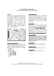
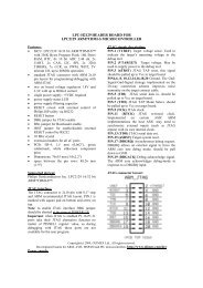
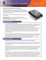
6 l <strong>POP</strong>-<strong>BOT</strong> : The Arduino Compatible Mobile Robot kit1.2 Microcontroller components information1.2.1 <strong>POP</strong>-168 microcontroller moduleThe Arduino <strong>POP</strong>-168 is a flexible board with no hidden components which allowsfull development of its features with AVR Standard tools like the like IAR C/C++ ,MikroElektronika Mikro BASIC/ MikroPascal for AVR, and also the open-source tool WINAVR:AVRGCC for Windows ... etc.Arduino <strong>POP</strong>-168 use the ATmega168 of AVR microcontroller from Atmel(www.atmel.com). Arduino <strong>POP</strong>-168ís oin assignment is similar BASIC Stamp module(www.parallax.com). It includes RS-232 serial port communication circuit for downloadingand data communication with computer. Arduino <strong>POP</strong>-168 moduleís hardware iscompatibled with Arduino-mini in Arduino project (www.arduino.cc/en)The complete schematic diagram of Arduino <strong>POP</strong>-168 module is shown in figure 1-1.The summarize features of <strong>POP</strong>-168 module is as follows :l ATmega168 on board with 10-bit ADC converter, 16KB flash programmemory, 512-byte EEPROM, 1KB RAM, 16MHz clockl Built-in RS-232 interface for Communicationl Immediate code upload with the built-in Bootloaderl Reset Button for reset capabilityl Small Form Factor for compact size developmentl ISP port for programming with the PX-400/PX-4000 devicel SMD Leds for indicationsl Fully compatible with the Ardruino Projectl 16 I/O pin assignement compatible i-Stamp/i-Stamp2P24 modulel Supply voltage range +3.3 to +5V 50mA1.2.2 RBX-168 Robot controller board for Arduino <strong>POP</strong>-168The RBX-168Robot controller board is a complete, low-cost development platformdesigned for those interested in learning and using Arduino <strong>POP</strong>-168 module in roboticapplications. Its compact size, convenient features, and low price make it an ideal toolfor the student and educator. Figure 1-2 shows the layout of RBX-168 board and completeschematic diagram of its is shown in the figure 1-3. The summarized technical feature ofthe RBX-168 board is as follows :
<strong>POP</strong>-<strong>BOT</strong> : The Arduino Compatible Mobile Robot kit l 7+5V+5VR14k7+5V +5VLED1BlueR2 R310k 4k7LED2GreenR44k7GNDRST+5VPB1PB0PD7PD6PD5PD4PD3PD2PIN13+5VGNDGNDGNDGNDVccK1AVRIn-SystemProgrammingConnectorMISOSCKRSTPB2MOSISW1BLBootloaderMode switch+5VC10.1FR5R6R7R8C20.1FPIN24R5-R8150 x4PB5AVCCAN6AREFAGNDAN7AN0AN1+5VPB4AN2PB3PB2AN3AN4PB1PB0AN5RSTPD7PD6PD0PD1PD5IC1ATMega168-20AU(TQFP32)PD2PB7PB6VCCGNDVCCGNDPD4PD3CR116MHz+5VC30.1FR968C60.1F+5VC40.1F45109R1015021516IC2MAX323213786C70.1FC50.1FPIN1PIN12TXRXGNDAN0AN1AN2AN3AN4AN5AN6AN7+5VdcRESETGNDBlue LED operation indicatorProgram mode : Turn-onRun mode : Indicates the Di 13 port logic statusGNDGNDGNDGND+VDDISP connectorpin assignmentBL switch for programming mode selectionDB-9 female connectorconnect to computer'sserial or COM portDi 12 (PB4:MISO)Di 13 (PB5:SCK) Blue LEDRESETDi 10 (PB2:SS) PWMDi 11 (PB3:MOSI) PWM235NCGNDRESETVDD (+5Vdc)Di 9/PWM (PB1)Di 8 (PB0)Di 7 (PD7)Di 6/PWM (PD6)Di 5/PWM (PD5)Di 4 (PD4)Di 3/PWM (PD3)ATMEGA1681 12TxDRxDNCGNDAn0 (PC0)An 1 (PC1)An2 (PC2)An 3 (PC3)An4/SDA (PC4)An5/SCL (PC5)An 6 (AN6)An 7 (AN7) Di 2 (PD2)13<strong>POP</strong>-168Green LED(power)Figure 1-1 Schematic diagram, Pin assignment and simple connection of <strong>POP</strong>-168 microcontroller module
8 l <strong>POP</strong>-<strong>BOT</strong> : The Arduino Compatible Mobile Robot kitl Screw terminal block for battery connections. It supports +4.8 to +12Vdcand has an on-board power switch.l +5Vdc switching regulator power supply circuit. Its regulates the supplyvoltage for <strong>POP</strong>-168 module and all sensor ports.l 2-push button switch are connected with the digital port 2 (Di2) and 4(Di4). Also connnedt with LED for indicator the operation.l 5-Universal port support Analog input function and Digital input/outputfunction; An1 (Di15) to An5 (Di19)l 2-Analog input port ; An6 and An7. Both port pin are analog input only.l I 2 C bus port; An4 (SDA) and An5 (SCL)l RS-232 serial port interfacing.l 2-ch. DC motor driver with indicators. Support motor voltage 2.5 to 13.5Vdc.l 2-Servo motor output; connect with the digital port 7 (Di7) and 8 (Di8).l Piezo speaker connections (do not show in the figure 1-2; it is fixed at bottomcircuit board of RBX-1689 board. It is connected with <strong>POP</strong>-168 An0/Di14 pin.RS-232 port(support the USB to serial converter cable)Supply voltage terminalMotor indicatorPOWER switch4-12VdcON+ ONRS-23214: Speaker3 : MotorA15 : MotorA29 : MotorB16 : MotorB2MOTORABDC motor outputPOWER indicatorLow batteryindicatorArduino <strong>POP</strong>-168univeral portPOWERA614/A018/SDA/A4 19/SCL/A515/A116/A2BATRESETPort functionNumber : DigitalAx : Analog pin xA7112ATMEGA168<strong>POP</strong>-16813SERVO PORT- +Vm8-+Vm7Di2 Di4Program mode button(on the Arduino <strong>POP</strong>-168 module)Servo motor outputLED and Buttonfor demonstrationI/O interfacingAnalog inputRESET switchArduino <strong>POP</strong>-168 moduleFigure 1-2 The layout of RBX-168 controller board
<strong>POP</strong>-<strong>BOT</strong> : The Arduino Compatible Mobile Robot kit l 9J1DOWNLOADRJ-11 6P4CRxDTxDDTRGND1234K8An7 +5VK7An6+5VK619/A5/SCL+5VK518/A4/SDA +5VK417/A3+5VK316/A2 +5VK215/A1+5VLED3P2R5510S1Di2LED4P4R7510S2Di4+5V+5VR6220R8220+5V12RxDTxD21SW1OND11N5819+Vm12SK1<strong>POP</strong>-168socketAn7RESET22K1BATT.4.8-12V+5VR44.7kC1100F16VIC1KIA703111An6SW2RESET108An59 An4An3An0/Di145C510F16V7An2SP1PIEZO6An114Di3/PWM16Di5/PWMDi9/PWM13 Di2Di6/PWM2017423+Vm15Di418Di7 Di7-SERVO1Di819K9SERVO1K10SERVO2+VmGNDDi8-SERVO2+VmGND1+VRESETGND2SSSGR11k3LED1LOW-BAT+5V1920211223171615FDS6680DDDDIC2KIA78R05G O IL110uHC2100F10VR247kQ1FDS6680A+Vm13 14 24STBYVccAIN1AIN2PWMABIN1BIN2PWMBIC4TB6612FNGAO1AO1 2AO25AO2BO1BO1BO2BO2161112783 4 9 10 18NCP1450EXT GNDKIA7031CE OUT NC+-OD2MBR340IC3NCP1450-5.05CE4GNDOUTC60.1/63VR91kLED5MOTOR A-DIR.LED6MOTOR B-DIR.R101kC70.1/63VC31000F6.3VC40.01F50VK11MOTOR-AK12MOTOR-B+5VR31kLED2ONFigure 1-3 The completely schematic diagram of RBX-168 controller board
10 l <strong>POP</strong>-<strong>BOT</strong> : The Arduino Compatible Mobile Robot kit1.3 Output device features1.3.1 DC motor gearboxThis robot kit provides 48:1 ratio DC motor gearbox; model BO-2 with IDC connectorcable. This is features :l Operating voltage is +3 to +9Vdcl Current consumption 130mA @ +6Vdc and no load)l Average speed 170 to 250 round per minute (RPM) @ +6V and no loadl Weight is 30 gramsl Minimum torque is 0.5 kg.cm.l Attached with the plastic mounting with 5 of insert nutsl 42 x 45 x 22.7 mm. (WxLxH) dimension1.3.2 Standard RC servo motorThe standard servo is ideal for robotics and basic movement projects. These servoswill allow a movement range of 0 to 180 degrees. The servo output gear shaft is a standardFutaba configuration. Technical Specifications are :l Operating voltage is 6Vdc max.l Speed 0 deg to 180 deg in 1.5 seconds on average.l Weight 45.0 grams/1.59ozl Torque 3.40 kg-cm/47oz-inl Size mm (L x W x H) 40.5x20.0x38.0
<strong>POP</strong>-<strong>BOT</strong> : The Arduino Compatible Mobile Robot kit l 111.3.3 SLCD16x2 : 16 characters 2 lines Serial LCD moduleThe 16x2 Serial LCD module provides a simple way to display data from microcontroller.The module requires only one I/O pin, +5 V and ground to function. Simpleserial data out commands can be used in the Arduino <strong>POP</strong>-168 module to communicatewith the module at 2400 and 9600 baud.Features of the 16x2 Serial LCD Module:l Serial Input with Invert/Non-invert TTL logic level.l 1/8 or 1/16 Duty can be selected by jumper.l Scott Edwardsís LCD Serial Backpack TM command compatible additionwith Extended Command that make LCD control easier.l Operation with +5 Vdc supplyl SLCD16x2 provides a brightness adjustment with variable resistor atBRIGHTNESS position.l Interfacing connector has 3 pins : +5V Supply voltage (+), Serial data input(S) and Ground (G).
12 l <strong>POP</strong>-<strong>BOT</strong> : The Arduino Compatible Mobile Robot kit1.4 Sensor module features1.4.1 Switch module/Touch sensorLED1R1510IndicatorR210kR3220+VDATASignal outputS1SwitchGNDThe switch input is used to detect collision at logic ì0î. Two sets along with theconnecting cable are provided.1.4.2 ZX-03 : Infrared reflector sensorThe heart of this sensor is TCRT5000 reflective object sensor. It is designed for closeproximity infrared (IR) detection. Thereís an infrared diode behind its transparent bluewindow and an infrared transistor behind its black window. When the infrared emitted bythe diode reflects off a surface and returns to the black window, it strikes the infraredtransistorís base, causing it to conduct current. The more infrared incident on the transistorísbase, the more current it conducts. When used as an analog sensor, the ZX-03 can detectshades of gray on paper and distances over a short range if the light in the room remainsconstant.The suitable distance from sensor to line or floor is during 3 to 8 mm. The outputSignal connector+VOUTTCRT5000Infrared ReflectorGND10k510voltage is during 0.1 to 4.8V and digital value from10-bit A/D converter is 20 to 1,000. Thus,ZX-03 will suitable to apply to line tracking sensor.
<strong>POP</strong>-<strong>BOT</strong> : The Arduino Compatible Mobile Robot kit l 131.4.3 GP2D120 Infrared distance sensorOne of the special sensors in robotics is the GP2D120. It is an Infrared Distancesensor. Some people call it the IR Ranger. With the GP2D120 module, it adds the distancemeasuring and Obstacle detection using infrared light feature to your robot. YourMicroCamp robot can avoid obstacles without having to make any physical contact.Infrared LED transmitterInfrared ReceiverGP2D120VoutGNDVccFeatures of the GP2D120 modulel Uses Infrared light reflection to measure rangel Can measure a range from 4 to 30 cm.l 4. 5 to 5 V power supply and 33mA electric currentl The output voltage range is 0.4 to 2.4V when supplied by +5VGP2D120 Infrared Ranger module has 3 terminals: Power input (Vcc), Ground (GND)and Voltage output (Vout). To read the voltage values from the GP2D120, you must waittill after the acknowledgement period which is around 32 to 52.9 ms.The output voltage of GP2D120 at a range of 30 cm and +5V power supply isbetween 0.25 to 0.55V, with the mean being 0.4V. At the range of 4 cm., the outputvoltage will change at 2.25V± 0.3V.
14 l <strong>POP</strong>-<strong>BOT</strong> : The Arduino Compatible Mobile Robot kit1.5 <strong>POP</strong>-<strong>BOT</strong> cable informationThe <strong>POP</strong>-<strong>BOT</strong> mobile robot kit includes some signal cables for the interfacingbetween the controller board, sensor module and the computer. They includes the JST3AA-8 cables for interconnection to the sensor module, UCON-4 the USB to RS-232 convertercable for interfacing with the computer.1.5.1 JST3AA-8 cableThis is an INEX standard cable, 3-wires combined with 2mm. The JST connector is ateach end. 8 inches (20cm.) in length. Used for connecting between microcontroller boardand all the sensor modules in the <strong>POP</strong>-<strong>BOT</strong> robot kit. The wire assignment is shown in thediagram below.2mm. pitchGNDS+5VGNDS/Data+5V2mm. pitch1.5.2 UCON-4 USB to Serial port converter cableThis is used to connect between the computerís USB port and the RBX-168 controllerboard. The cableís end uses a Modular plug RJ-11 6P4C (6-pins form and 4-contacts) ItsLength is 1.5 meters approximation. The cable assignment is shown in the diagram below.MCU_TxDMCU_RxDMCU_DTRGNDThis cable requires +5V from USB port and support USB 1.0/2.0. User can set thebaudrate up to 115,200 bit per second. Requires the driver installation before using.
<strong>POP</strong>-<strong>BOT</strong> : The Arduino Compatible Mobile Robot kit l 151.6 Mechnical prt features1.6.1 Circle wheel and Tire setIncludes 2 pairs of the suittable circle wheel for BO-2 DC motor gearbox and treadrubber tire. Fix the wheel with gearbox shaft by 2mm. self-tapping screws1.6.2 Plastic grid plate setIncludes each of the universal plastic grid palte 2 sizes; 80x60mm. and 80x80mm.Each plate provides 3mm. diameter holes with 5mm. pitch.1.6.3 Circle baseThis base is injected from high quality ABS plastic. Diameter is ...........mm. It has 2free ball wheels at both side. This base has many 3mm. holes for fixing the controller board,sensors and more mechanical parts.
16 l <strong>POP</strong>-<strong>BOT</strong> : The Arduino Compatible Mobile Robot kit1.6.4 Plastic joiners60 pieces of varied color joiners made from PVC plastic. They can be connectedtogether or by using screws and 3 mm nuts in installation. There are 4 types; Right angle,Obtuse, Straight joiner and Hole straight joiner.1.6.5 Strip joinersThey are made from plastic. Each joiner has 3mm. hole 5mm. pitch. Each joinercan connect for lenght expansion. They are 4 pieces of 3 sizes; 3, 5 and 12 holes type.Total 12 pieces.1.6.6 Box holderIt is injected plastic box for supporting the RBX-168 controller board. It has some of3mm. hole for fixing with any platform.
<strong>POP</strong>-<strong>BOT</strong> : The Arduino Compatible Mobile Robot kit l 171.6.7 Right-angle metal shaftIt is 7.5mm. width right-angle metal shaft. Each shaft has 3mm. hole for inserting thescrew to fix with another structures. The set includes 4 pieces of 1x2, 2x2 and 2x5 holesmetal shaft.1.6.8 Screw and Nut setIncludes 2 of 2mm. self-tapping screws, 4 of 3x8mm. M3 screws, 30 of 3x10mm. M3screws, 4 of 3x15 mm. M3 screws, 4 of 3x40mm. M3 screws, 10 of 3x8mm. flat-head screwsand 30 of 3mm. M3 nuts.1.6.9 Metal spacerThey are metal parts for supporting the plate and sensor board. They are madefrom nikle plating metal. Includes 6 of 33mm. metal hexagonal spacers. Each standoff has3mm. thread through-hole.1.6.10 Plastic spacerThey are some mechanical parts for supporting the plate and sensor board. This kitincludes 4 pieces set of plastic spacer (3mm., 10mm., 15mm. and 25mm.) 4 sets
18 l <strong>POP</strong>-<strong>BOT</strong> : The Arduino Compatible Mobile Robot kit
<strong>POP</strong>-<strong>BOT</strong> : The Arduino Compatible Mobile Robot kit l 192 : Building <strong>POP</strong>-<strong>BOT</strong> mobile robot2.1 <strong>POP</strong>-<strong>BOT</strong> featuresl Move with DC motor gearboxes and wheels.l Controlled by Arduino <strong>POP</strong>-168 microcontroller module. Based on ATmega168microcontroller.l Programmable via serial port and support the USB to serial port converter.l Support variety of sensors such as Infrared refelctor for line tacking, Touch sensor forobject avoiding, Infrared ranger or Distance sensor for touchless object avoiding.l Support the wired remote control included PlayStation controller.l Support the wireless serial data communication module suhc as Xbee, XBee-Pro andBluetooth.l Includes 16x2 Serial LCD module for monitoring and display operting status.l 2 servo motor driver port. Support small RC servo motor 4.8 to 6V.l Requires 4 of AA batteries. The Alcaline, Evolta and Rechargeable Ni-MH arerecommendded.
20 l <strong>POP</strong>-<strong>BOT</strong> : The Arduino Compatible Mobile Robot kit2.2 Part listCircle base x 1 RBX-168 board with <strong>POP</strong>-168 x1 Box holder x 1Circle wheel and tire x 2 DC motor gearbox x 2 33mm. metal spacer x 4Serial LCDmodule x 1Infared reflector x 2GP2D120 distance sensor x 12mm. self-tapping screw x 2Plastic joinersRight angled metalshaft 2x2 x 2Plastic spacer setScrew and Nut set
<strong>POP</strong>-<strong>BOT</strong> : The Arduino Compatible Mobile Robot kit l 212.3 Buiding procedure(1) Attache both DC motor gearboxes with the Box holder by 3x8mm. flat screws.3x8mm. flat screws3x8mm. flat screws(2) Attache 2 of 33mm. metal spacers with the Box holder by by 3x8mm. flat screws at theposition following the pictures below.3x8mm. flat screws3x8mm. flat screws(3) Insert the wheel with tire to DC motor gearboxís shaft and fix with 2mm. self-tappingscrews.
22 l <strong>POP</strong>-<strong>BOT</strong> : The Arduino Compatible Mobile Robot kit(4) Attach the gearbox structure as shown in step (3) with the circle base by using 3x6mm.screws at the position following the pictures below. See the weheelís position is the centerof base.(5) Insert the 3x10mm. screw via the Infrared reflectorís hole and 3mm. plastic spacer.Make 2 sets.Infrared reflector sensor3mm. plasticspacer3x10mm. screw(6) Fix both Infrared reflector structures from step (5) at the in-front-of robot base both sideby using 3mm. nut.Infrared reflectorsensors3mm. nutBaseInfrared reflector
<strong>POP</strong>-<strong>BOT</strong> : The Arduino Compatible Mobile Robot kit l 23(7) Now the <strong>POP</strong>-<strong>BOT</strong> chasis with Infrared reflector sensors is ready.(8) Attach the Right angle joiner with Switch module by using 3x10mm. screw and 3mm.nut following connect the obtuse joiner at the end of the right angle joiner. Make 2 sets.Switch moduleObtuse joiner3mm. nut3x10mm. screw(9) Fix 2 pieces of Straight joiner at the front of robot chasis by using 3x6mm. screws and3mm. nuts. Next, connect the Switch structures from step (9) at the end of Straight joiners.
24 l <strong>POP</strong>-<strong>BOT</strong> : The Arduino Compatible Mobile Robot kit(10) Attach 2 of 33mm. metal spacers with SLCD16x2 module by using 3x6mm. screws.Next, fix the straight joiner at the end of spacer by using 3x10mm. screw.(11) Fix the SLCD16x2 structure from step (10) at the back of robot chasis following thepicture below by using 3x10mm. screws and 3mm. nuts(12) Put the RBX-168 board into the Box holder. Connect all cables. Start with Left motorcable to MOTOR A output, Right motor cable to MOTOR B output. Connect the left Infraredreflector cable to A7 pin, the right Infrared reflector cable to A6 pin. Next, connect thethe leftt switch module cable to 15/A1 pin, the right switch cable to 17/A3 and connectSLCD16x2 to 16/A2 pin.The <strong>POP</strong>-<strong>BOT</strong> is just ready for programming now.MOTOR AMOTOR B
<strong>POP</strong>-<strong>BOT</strong> : The Arduino Compatible Mobile Robot kit l 253 : Introduction to Arduino IDEArduino is an open-source electronics prototyping platform based on flexible, easyto-usehardware and software. Itís intended for artists, designers, hobbyists, and anyoneinterested in creating interactive objects or environments.*This chapter describe about introduction to Arduino. Begin with Installation, explainabout Arduino IDE components and Menu bar details.3.1 Installation software(1) Insert the <strong>POP</strong>-<strong>BOT</strong> CD-ROM to CD drive of your computer.(2) Enter the Software à Arduino folder. Find the ArduinoSetup.exe and doubleclick.The installation will start .<strong>POP</strong>-<strong>BOT</strong> CD-ROM contains the Arduino software V15 , all example codes for <strong>POP</strong>-<strong>BOT</strong> activities and nescessary library files. You can get the latest version of Arduino atwww.arduino.cc. However you need to ensure the correct path of <strong>POP</strong>-<strong>BOT</strong> library afteryou upgrade the new version of Arduino IDE.* Introduction paragraph is from Arduino website (www.arduino.cc)
26 l <strong>POP</strong>-<strong>BOT</strong> : The Arduino Compatible Mobile Robot kit3.2 Arduino environmentAfter starting Arduino IDE, the main window will appear as shwon in the figure 3-1.The Arduino includes the environments as follows.l Menu : Select the operation commandl Toolbar : Includes all most command buttonl Tabs : Allows you to manage sketches with more than one file (each ofwhich appears in its own tab).l Text editor : Text editor area for creating the sketch.l Message area : Shows the program operation status such as compiling result.l Text area : The space demonstrates compiling information and Serial dataTerminal window if enable.TabMenuTools barText EditorMessage areaText areaFigure 3-1 Arduino environment
<strong>POP</strong>-<strong>BOT</strong> : The Arduino Compatible Mobile Robot kit l 273.3 Menu bar3.3.1 FileThe Arduino calls the code as Sketch. This menu contains many commands likeopen, save and close the sketch as follows :YYMMDDa".l New : Creates a new sketch, named is the current date format "sketch_l Sketchbook- Open : Open the exist sketch.- Example : Open the example sketch.l Save : Save the current sketchl Save as : Save the current sketch as another name.l Upload to I/O board : Uploads your code to the Arduino I/O board (<strong>POP</strong>-168 module). Make sure to save or verify your sketch before uploading it.l Preference : Set some preference of Arduino environmentl Quit : Exit the Arduino IDE3.3.2 EditThe Edit menu provides a series of commands for editing the Arduino files.l Undo : Reverses the last command or the last entry typed.l Redo : Reverses the action of the last Undo command. This option is onlyavailable, if there has already been an Undo action.l Cut : Removes and copies selected text to the clipboard.l Copy : Copies selected text to the clipboard.l Paste : Inserts the contents of the clipboard at the location of the cursor,and replaces any selected text.editor.l Select All : Selects all of the text in the file which is currently open in the textl Find : Finds an occurance of a text string within the file open in the texteditor and gives the option to replace it with a different text.l Find Next : Finds the next occurance of a text string within the file open inthe text editor.
28 l <strong>POP</strong>-<strong>BOT</strong> : The Arduino Compatible Mobile Robot kit3.3.3 SketchThis menu provides a series of commands for compile the code and manage library.l Verify/Compile : Verify and compiles the codel Stop : Stops current activity.l Add file : Opens a file navigator. Select a code files to add it to the sketches"data" directory.l Import Library : Import the addition library.l Show Sketch folder : Opens the directory for the current sketch.3.3.4 ToolsThis menu provides commands about tools for developing the Arduino sketch andsetting up the Arduino hardware.l Auto Format : Attempts to format the code into a more human-readablelayout. Auto Format was previously called Beautify.l Archive Sketch : Compress the current sketch to the zip file.l Export Folder : Open the folder that contain the curretn sketch.Arduino Minil Board : Choose the Arduino hardware. For <strong>POP</strong>-<strong>BOT</strong>, choose <strong>POP</strong>-168 orl Serial Port :Allows to select which serial port to use as default for uploadingcode to the Arduino I/O Board or monitor data coming from it. The data coming from theArduino I/O Board is printed in character format in the text area region of the console.3.3.5 HelpThis menu contains many information in HTML format for supporting the Arduino user.l Getting Start : Opens the How to start Arduino.l Troubleshooting : Suggest the solution when meet the problem in Arduino.l Environment : Describe about Arduino environmentsl Reference : Opens the reference in the default Web browser. Includesreference for the language, programming environment, libraries, and a language comparison.Arduino.homepage.l Frequently Asked Question : See the popular question and answer aboutl Visit www.arduino.cc : Opens default Web browser to the Arduinol About Arduino : Opens a concise information panel about the software.
<strong>POP</strong>-<strong>BOT</strong> : The Arduino Compatible Mobile Robot kit l 293.4 Tools barVerify/Compile : Checks your code for errors.Stop : Stops the serial monitor, or unhighlight other buttons.New : Creates a new sketch.Open : Presents a menu of all the sketches in your sketchbook.Save : Saves your sketch.Upload to I/O Board : Uploads your code to the Arduino I/O board (<strong>POP</strong>-168module). Make sure to save or verify your sketch before uploading it.Serial Monitor : Displays serial data being sent from the Arduino board (USB orserial board). To send data to the board, enter text and click on the "send" button or pressenter. Choose the baud rate from the drop-down that matches the rate passed toSerial.begin in your sketch. Note that on Mac or Linux, the Arduino board will reset (rerunyour sketch from the beginning) when you connect with the serial monitor.3.5 Arduino programming reference noticeThis activity book will not describe about Arduino programming. You can read andmake the understanding about Arduino syntax and programming reference from Helpmenu or learn from Arduino website at www.arduino.cc.Addition, you can learn from 40-pages of Arduino Programming Notebook. Alsodownload rom Arduino website in Playground page.
30 l <strong>POP</strong>-<strong>BOT</strong> : The Arduino Compatible Mobile Robot kit
<strong>POP</strong>-<strong>BOT</strong> : The Arduino Compatible Mobile Robot kit l 314 : <strong>POP</strong>-<strong>BOT</strong> program development by ArduinoThe <strong>POP</strong>-<strong>BOT</strong> program development can summarize as the diagram following thefigure 4-1.Installtion software tools- Arduino IDE :C/C++ programming development tools.Includes Text editor, Compiler and Upload thecode to microcontroller- USB to RS-232 serial port converter driverCreate the sketch fileMake the C/C++ code on Arduino IDECompileUpload the codeUSB portUpload the code via USB port1. Connect UCON-4 cable to USB portand <strong>POP</strong>-<strong>BOT</strong>.2. Check the USB Serial port address.3. Choose <strong>POP</strong>-<strong>BOT</strong> to Program mode(upload mode).4. Upload the code.Run the codeAfter uplaod the code successfully, pressRESET switch on the <strong>POP</strong>-168 module of<strong>POP</strong>-<strong>BOT</strong>.The <strong>POP</strong>-<strong>BOT</strong> run following the uploadedcode.Figure 4-1 Programming development diagram of <strong>POP</strong>-<strong>BOT</strong> by using ArduinoIDE
32 l <strong>POP</strong>-<strong>BOT</strong> : The Arduino Compatible Mobile Robot kit4.1 Preparing the UCON-4; USB to RS-232 serial portconverter cableThe <strong>POP</strong>-<strong>BOT</strong> requires computer interface and Arduino for uploading the code.Normally use RS-232 serial port or COM port. For modern computer provide the maininterface port as USB. Therefore the USB to RS-232serial port converter is required. In ther<strong>POP</strong>-<strong>BOT</strong> kit preaprares the UCON-4 cable for this purpose.Before using the UCON-4 cable, you must install the suitable driver and check someconfiguration.4.1.1 Driver installationDouble click at USBDriverInstallerV2.0.0.exe file from <strong>POP</strong>-<strong>BOT</strong> bundled CD-ROM tostart the driver instalation. The installation dialogue-box will appear below.4.1.2 Check the USB serial port address(1) Plug the USB cable to USB port and <strong>POP</strong>-<strong>BOT</strong> controller board. Wait a moment.(2) Check the Virtual COM port or USB Serial port address by clicking Start à ControlPanel à System à Hardware à Device Manager
<strong>POP</strong>-<strong>BOT</strong> : The Arduino Compatible Mobile Robot kit l 33(3) See the list of USB serial port and remember the COM port address to work withUCON-4 cable. Normally it will create COM3 or above. In this example is COM44.1.3 UCON-4 cable with Arduino operation noticeNormally Arduino software can interface with COM port not higher than COM9.Thus, user must make sure the USB serial port address not higher than COM9. If higher,please do following procedure.(1) Connect the UCON-4 cable to Computer USB port.(2) Check the COM port address by clicking at Start à Control Panel àSystem(3) Select the Hardware tab and click on the Device Manager button.(4) Check the hardware listing. At the Port listing, you will found USB Serial port(COM x).If COM port is higher than COM9 (this example is COM10), please click on theright-button mouse and select to Properties
34 l <strong>POP</strong>-<strong>BOT</strong> : The Arduino Compatible Mobile Robot kit(5) The USB Serial Port (COM10) Properties window will appear. Select the Port Settingtab and set all value following the figure below and click on the Advance button(6) The Advanced Setting for COM10 will appear. Click on the COM Port Numberbox to change to COM4 or another port in range COM1 to COM9.
<strong>POP</strong>-<strong>BOT</strong> : The Arduino Compatible Mobile Robot kit l 35(7) Set the value following the figure below. Especially at the Latency Timer (msec)suggested to set to 1 and check the box at Serial Enumerator. Click OK button.(8) Go back to the USB Serial Port Properties. Now the COM port number at the titlebar will change to COM4. Click on the OK button.(9) Remove the UCON-4 cable from USB port and re-plug again. Check the USBSerial port address. The new address must be COM4. Now the UCON-4 cable ready forusing with Arduino IDE software.
36 l <strong>POP</strong>-<strong>BOT</strong> : The Arduino Compatible Mobile Robot kit4.2 Getting start <strong>POP</strong>-<strong>BOT</strong> with ArduinoRun Arduino IDE by clickng the Start à All Programs à <strong>POP</strong>-168 Software Packageà ArduinoThe first launch of Arduino show the screen below.4.2.1 ARduino <strong>POP</strong>-168 hardware configuration4.2.1.1 Select microcontroller chipSelect the menu Tools à Board à <strong>POP</strong>-168 or Arduino Mini (can use both versions)
<strong>POP</strong>-<strong>BOT</strong> : The Arduino Compatible Mobile Robot kit l 374.2.1.2 Select the COM portUploading the sketch from Arduino IDE to <strong>POP</strong>-168 module requires serial portcommunication. It can work with virtual COM port that created from USB to Serial port converter.Select menu Tools à Serial Port . You can select the target COM port.Normally on-board serial port will be COM1 or COM2. For USB Serial port address willbe COM3 or higher. But Arduinoi can support COM port not higher COM9.4.2.2 Open the example sketch fileSelect menu File à Sletchbook à Examples à Digital à BlinkThe example code; Blink.pde will appear on the text editor area.
1AB38 l <strong>POP</strong>-<strong>BOT</strong> : The Arduino Compatible Mobile Robot kit4.2.3 Compile the sketchAfter open the sketch file and edit ready, you can compile theis sketch by selectingthe menu Sketch à Verify/Compile or click on the buttonThe status bar at the bottom of main screen will display the compilation status. Ifcompile no error, it reports Done compiling and the Text area will display message ofbinary sketch size.4.2.4 Uploading the sketch to <strong>POP</strong>-168 module<strong>Download</strong>ing the machine code from compiling to Arduino hardware is calledUploading. You must prepare the Aruino hardware ready for uploading by setting the<strong>POP</strong>-168 to Bootloader mode. The procedure is :(1) Connect the <strong>POP</strong>-<strong>BOT</strong> with your computer COM port by CX-4 cable or via USB toSerial port converter.Connect direct to COM port(if available)CX-4 cableConnect to USB portUCON-232SUSB to Serial port converterComputer4-12VdcON+ONRS-23214: Speaker3 : MotorA15 : MotorA29 : MotorB16 : MotorB2MOTORPOWERBATA615/A114/A018/SDA/A4 19/SCL/A516/A2Port functionNumber : DigitalAx : Analog pin xA7RESET12ATMEGA168<strong>POP</strong>-16813SERVO PORT- +Vm8- +Vm7Di2 Di4<strong>POP</strong>-<strong>BOT</strong>
11BABA<strong>POP</strong>-<strong>BOT</strong> : The Arduino Compatible Mobile Robot kit • 39(2) Set <strong>POP</strong>-168 module to program mode. It has 2 options.(2.1) Use RESET switch on RBX-168 board and BL switch on <strong>POP</strong>-168 module(2.1.1) Turn on <strong>POP</strong>-<strong>BOT</strong>(2.1.2) Press and hold RESET switch on the RBX-168 controller board.(2.1.3) Press and hold BL switch on the <strong>POP</strong>-168 module.4-12VdcON+ONRS-232POWER BATA615/A114/A018/SDA/A4 19/SCL/A516/A2Port functionNumber : DigitalAx : Analog pin xA7RESET1214: Speaker3 : MotorA15 : MotorA29 : MotorB16 : MotorB213ATMEGA168<strong>POP</strong>-168MOTORSERVO PORT- +Vm8- +Vm7Di2 Di41 Press and hold RESET (black) switch2 Press and hold BL (white) switch<strong>POP</strong>-<strong>BOT</strong>(2.1.4) Release the RESET switch.(2.1.5) Release the BL switch following.If Blue LED on <strong>POP</strong>-168 is turned on and not blink, then <strong>POP</strong>-168 hadentered Bootloader mode and ready to uploaded.3Release RESET (black) switch4-12VdcON+ONRS-232POWER BATA615/A114/A018/SDA/A4 19/SCL/A516/A2Port functionNumber : DigitalAx : Analog pin xA7RESET1214: Speaker3 : MotorA15 : MotorA29 : MotorB16 : MotorB213ATMEG A168<strong>POP</strong>-168MOTORSERVO PORT- +Vm8- +Vm7Di2 Di44Release BL (white) switch5 Blue LED on the <strong>POP</strong>-168 moduleis turned on. Indicates <strong>POP</strong>-168 isentered to Program mode<strong>POP</strong>-<strong>BOT</strong>
140 • <strong>POP</strong>-<strong>BOT</strong> : The Arduino Compatible Mobile Robot kit(2.2) Use POWER T swtich on RBX-168 board and BL switch on <strong>POP</strong>-168 module(2.2.1) Turn off the <strong>POP</strong>-<strong>BOT</strong>.(2.2.2) Press and hold BL switch.1Turn-off POWER switch4-12VdcON+ONRS-23214: Speaker3 : MotorA15 : MotorA29 : MotorB16 : MotorB2MOTORB APOWERBATA615/A114/A018/SDA/A4 19/SCL/A516/A2Port functionNumber : DigitalAx : Analog pin xA7RESET12ATMEG A168<strong>POP</strong>-16813SERVO PORT- +Vm8- +Vm7Di2 Di42Press and hold BL (white) switch<strong>POP</strong>-<strong>BOT</strong>(2.2.3) Turn-on the POWER switch(2.2.4) Release the BL switchIf Blue LED on <strong>POP</strong>-168 is turned on and not blink, then <strong>POP</strong>-168 hadentered Bootloader mode and ready to uploaded.(3) At Arduino IDE, select menu File à Upload to I/O Board. Wait for uploading.(4) When uploading complete, the status bar at the bottom of main screen willdisplay message Done Uploading .the <strong>POP</strong>-<strong>BOT</strong>.(5) After the uploading is finished, press RESET switch again. The sketch will run onThe LED at Di13 (Blue LED) on the <strong>POP</strong>-168 module blinks 1 second rate.
<strong>POP</strong>-<strong>BOT</strong> : The Arduino Compatible Mobile Robot kit l 415 : <strong>POP</strong>-<strong>BOT</strong> movement activitiesThe <strong>POP</strong>-<strong>BOT</strong> has 2 channels of DC motor drivers. You can control the speed anddirection of DC motor rotation with software. Because DC motor is driven by PWM (Pulsewidth modulation) signal. In this section describe how to drive DC motor with PWM andhow to generate PWM signal of Arduino <strong>POP</strong>-168 microcontroller in C programming.5.1 Basic operation of driving DC motor with PWMBy changing (modulating) the width of the pulse applied to the DC motor we canincrease or decrease the amount of power provided to the motor, thereby increasing ordecreasing the motor speed. Notice that, although the voltage has a fixed amplitude, ithas a variable duty cycle. That means the wider the pulse, the higher the speed.Refer Figure 5-1, the Vs supplies PWM signal to DC motor. The speed is dependent onTon time (ON time of motor). At this time, DC motor will receive the full voltage; Vm. If Toníswidth is more, DC motor is received more voltage. It rotate in high speed. The ratio of Tontime in percentage with period (T) is called Duty cycle. You can calculate this as follows :% duty cycle =Ton100 .................................................................(5.1)Ton ToffPWM frequency =1Ton Toff1T...............................................................(5.2)Average DC motor voltage drop = Supply voltage x duty cycle (%) .......(5.3)RsVmVsMVmTontTToffFigure 5-1 : The PWM signal for driving DC motor
42 l <strong>POP</strong>-<strong>BOT</strong> : The Arduino Compatible Mobile Robot kitVm (V)(A)(B)4.54 8 12 16 20 24 28 32Vm (V)10ms4.54 8 12 16 20 24 28 32Vm (V)t (ms)t (ms)Duty cycle = 4 x100% 20= 20%Average voltage = 4.5 x 20% = 0.9VDuty cycle = 10 x100% 20= 50%Average voltage = 4.5 x 50% = 2.25V(C4.518ms4 8 12 16 20 24 28 32Duty cycle = 18 x100% 20= 90%t (ms) Average voltage = 4.5 x 90% = 4.05VVm (V)(D)4.520msDuty cycle = 20 x100% 20= 100%4 8 12 16 20 24 28 32Average voltage = 4.5 x 100% = 4.5Vt (ms)Figure 5-2 : Shows the relation between the different duty cycle and voltageaccross the DC motor.Although the duty cycle is determine the motor speed. But DC motor can operateat limit frequency. If the PWM frequrency is over the limit, DC motor will stop because itsoperation reach to saturation point. The example PWM signal in figure 5-2 has 20 millisecondsperiod and 50Hz frequency.In Figure 5-2 (A) the PWM duty cycle is 20%. Motor will rotate with lowest speedbecause the voltage drop is only 0.9V.When increase the duty cycle in Figure 5-2 (B) and(C), voltage is applied to DC motor increase. Its speed is increase too.In Figure 5-2 (D) the voltage is applied to DC motor full level because duty cycle is100%. Thus, controlling the PWM duty cycle is a method of motor speed control.
<strong>POP</strong>-<strong>BOT</strong> : The Arduino Compatible Mobile Robot kit l 435.2 Arduino with PWMArduino has a special function to generate PWM signal and outs to any digital pins.It is analogWrite(). User can adjust PWM duty cycle from 0 to 100% with value between 0to 255.At value = 0, no PWM signal is occured. Voltage output as 0V.At value = 51, The PWM signal has positive pulse width 20% of period. Theduty cycle is equal to 20%.At value = 127, The PWM signal has positive pulse width half of period. Theduty cycle is equal to 50%.At value = 191, The PWM signal has positive pulse width 75% of period. Theduty cycle is equal to 75%.At value = 255, The PWM signal has full positive pulse width. The duty cycle isequal to 100%.The figure 5-2 shows the PWM signal at any duty cycle.0%20%50%75%100%Figure 5-2 shows the PWM signal at any duty cycle.
44 l <strong>POP</strong>-<strong>BOT</strong> : The Arduino Compatible Mobile Robot kitOutput voltage of PWM signal is average value relate the duty cycle. You cancalcualte from this relation below :Outout_voltage = (on_time / off_time) * max_voltageWe can use the PWM signal from analogWrite() function to adjust the LED brightnessor amplify to drive the DC motor. The Arduinoís pin that assigned to PWM output will outthe PWM continue until do the analogWrite() function in new period or excecutedigitalRead and digitalWrite funtion at same pin.Arduino <strong>POP</strong>-168 module has 4 analog output pins; it includes pin 3, 5, 6 and 9 (Di3,Di5, Di6 and Di9).The analogWrite function fornat isanalogWrite(pin,value);Thus; pin as The Arduino’s port pin 3, 5, 6 and 9value as Duty cycle value 0 to 255.
BA4-12VdcPOWERA6ONBATDi2 Di4113A7RESET<strong>POP</strong>-16812<strong>POP</strong>-<strong>BOT</strong> : The Arduino Compatible Mobile Robot kit l 45Activity 1 : <strong>POP</strong>-<strong>BOT</strong> basic movementActivity 1-1 Forward and Backward movementA1.1 Open the Arduino IDE and create the sketch code from Listing A1-1.A1.2 Set the <strong>POP</strong>-<strong>BOT</strong> into Program mode. Upload the sketch to the robot.A1.3 Turn-off power and Remove the download cable.A1.4 Make sure the robot is on a flat surface. Turn-on the power and observe the operation.The <strong>POP</strong>-<strong>BOT</strong> moves forward. See both LED motor indicators light in green color.After 1 second, both indicators change color to red and the robot moves backward.If this is incorrect you will need to re-connect the motor cable to its opposite port /polarity. Do this until your robot moves correctly. Once its done, Use this motor portconfiguration for all your programming activities from now on. The robot will move forwardand backward continually until you turn off its power./******************************************************************************** <strong>POP</strong>-<strong>BOT</strong> V1.0* Running Forward/Backward Full Speed********************************************************************************/void setup(){pinMode(3,OUTPUT);// Motor A1pinMode(5,OUTPUT);// Motor A2pinMode(6,OUTPUT);// Motor B2pinMode(9,OUTPUT);// Motor B1}void Forward(){// Robo-Spinner Go Forward RountinedigitalWrite(3,HIGH);digitalWrite(5,LOW);digitalWrite(6,HIGH);digitalWrite(9,LOW);}void Backward(){digitalWrite(3,LOW);digitalWrite(5,HIGH);digitalWrite(6,LOW);digitalWrite(9,HIGH);// Robo-Spinner Go Backward Rountine}void loop(){Forward();delay(1000);Backward();- oRobo - SpinnerR -Arduino<strong>POP</strong>Rrobotdelay(1000);}/******************************************************************************/Listing A1-1 : Forward_Backward.pde file; the Arduino sketch file for driving<strong>POP</strong>-<strong>BOT</strong> to forward and backward direction.- +Vm8- +Vm7SERVO PORTMOTORATMEGA16814: Speaker3 : MotorA15 : MotorA29 : MotorB16 : MotorB2Port functionNumber : DigitalAx : Analog pin xRS-23216/A215/A1+18/SDA/A4 19/SCL/A514/A0ON
BA4-12VdcPOWERA6+ONA7BATDi2 Di4113RESET<strong>POP</strong>-1681246 l <strong>POP</strong>-<strong>BOT</strong> : The Arduino Compatible Mobile Robot kitActivity 1-2 Circle-shape movement controlWith setting the different speed for each motor, it cause the robot move in circleshape.You can try with this procedure as follows :A1.5 Create a new sketch file and write the following C Codes shown in Listing A1-2.A1.6 Set the <strong>POP</strong>-<strong>BOT</strong> into Program mode. Upload the sketch to the robot.A1.7 Turn-off power and Remove the download cable.A1.8 Make sure the robot is on a flat surface. Turn-on the power and observe the robot.The robot moves with circle-shape continually until you press the button switch atDi4 pin of <strong>POP</strong>-<strong>BOT</strong> controller board to stop the robot movement./******************************************************************************** <strong>POP</strong>-<strong>BOT</strong> V1.0* Filename : MotorSpeedControl.pde* Left Motor Lowspeed and Right Motor Highspeed Robo-Spinner Run in Circle********************************************************************************/void setup(){pinMode(3,OUTPUT);// Motor A1pinMode(5,OUTPUT);// Motor A2pinMode(6,OUTPUT);// Motor B2pinMode(9,OUTPUT);// Motor B1pinMode(2,INPUT);// Switch LeftpinMode(4,INPUT);// Switch Right}void Forward(int Lspeed,int Rspeed){analogWrite(3,Lspeed);digitalWrite(5,LOW);analogWrite(6,Rspeed);digitalWrite(9,LOW);}void Motor_Stop(){digitalWrite(5,LOW);digitalWrite(3,LOW);digitalWrite(6,LOW);digitalWrite(9,LOW);}void loop(){Forward(80,255);// Circle runningif(digitalRead(4)==0){ // if Switch PressMotor_Stop();// Stopwhile(1);}}/******************************************************************************/Listing A1-2 : MotorSpeedControl.pde file; the Arduino sketch file for circlemovement of <strong>POP</strong>-<strong>BOT</strong>- +Vm8- +Vm7SERVO PORTMOTORATMEGA16814: Speaker3 : MotorA15 : MotorA29 : MotorB16 : MotorB2Port functionNumber : DigitalAx : Analog pin xRS-23216/A215/A119/SCL/A518/SDA/A414/A0ON- oRobo - SpinnerR -Arduino<strong>POP</strong>Rrobot
Di2 Di4BA13<strong>POP</strong>-168121RESETBATA7ONA6POWER4-12Vdc<strong>POP</strong>-<strong>BOT</strong> : The Arduino Compatible Mobile Robot kit l 47Activity 1-3 Square-shape movement controlA1.9 Create a new sketch file and write the following C Codes shown in Listing A1-3.A 1.10 Upload the sketch to the robot. Turn-off power and Remove the download cable.A1.11 Turn-on the power and observe the robot.The robot will be activated if SW1 or SW2 is being pressed. If you Press SW1, therobot will move forward and turn left continually, making a square. If you press SW2, theoperation is vice versa./******************************************************************************** Robo-Spinner V1.0* Filename : Rectangle_Running.pde* Running 90 Degree Turnleft And Turnright********************************************************************************/void setup(){pinMode(3,OUTPUT);// Motor A1pinMode(5,OUTPUT);// Motor A2pinMode(6,OUTPUT);// Motor B2pinMode(9,OUTPUT);// Motor B1pinMode(2,INPUT);// LeftSwitchpinMode(4,INPUT);}void Forward(int speed){analogWrite(3,speed);digitalWrite(5,LOW);analogWrite(6,speed);digitalWrite(9,LOW);}void Spin_Left(int speed){analogWrite(5,speed);digitalWrite(3,LOW);analogWrite(6,speed);digitalWrite(9,LOW);}void Spin_Right(int speed){analogWrite(3,speed);digitalWrite(5,LOW);analogWrite(9,speed);digitalWrite(6,LOW);}void loop(){if (digitalRead(2)==0){}while(1){Forward(125);delay(900);Spin_Left(125);// RightSwitch// Switch Di2 Press// Turnleft 90 degreedelay(400);}}if (digitalRead(4)==0){ // Switch Di4 Press}while(1){Forward(125);delay(900);Spin_Right(125);delay(400);}// Turnright 90 degreeListing A1-3 : Rectangle_Running.pde file; the Arduino sketch file forsquare-shape movement- +Vm8- +Vm7SERVO PORTMOTORATMEGA16814: Speaker3 : MotorA15 : MotorA29 : MotorB16 : MotorB2Port functionNumber : DigitalAx : Analog pin x- oRobo - SpinnerR -Arduino<strong>POP</strong>RrobotRS-23216/A215/A1+19/SCL/A518/SDA/A414/A0ON
BONABAA6+ON+ONA7BATBATDi2 Di4113ONA6A7<strong>POP</strong>-1681211312BAA6+A7+Vm - 8+Vm - 7BA11312+11312A6A7B A4-12VdcPOWERA6+ONBATRESETPort functionA7Number : DigitalAx : Analog pin xMOTOR+Vm - 8Di2 Di4113<strong>POP</strong>-16812ONBA4-12VdcPOWERA6+ONA7BATRESETPort functionNumber : DigitalAx : Analog pin x+Vm - 8+Vm - 7Di2 Di4113<strong>POP</strong>-1681248 l <strong>POP</strong>-<strong>BOT</strong> : The Arduino Compatible Mobile Robot kitActivity 2 : <strong>POP</strong>-<strong>BOT</strong> BumperActivity 2-1 Simple collision detectionThis activity is program the robot to detect the collision of both switches at the frontof the <strong>POP</strong>-<strong>BOT</strong> robot. After a collision is encountered, the robot will move backward andchange the its direction of movement.A2.1 Open the Arduino IDE and create the sketch code from Listing A2-1.A2.2 Set the <strong>POP</strong>-<strong>BOT</strong> into Program mode. Upload the sketch to the robot.A2.3 Turn-off power and Remove the download cable.A2.4 Prepare the demonstration area by placing and securing boxes or objects on thesurface.A2.5 Place the robot on the demonstration area. Turn-on the power and observe therobot.The <strong>POP</strong>-<strong>BOT</strong> will read both switch status from 15/A1 and 17/A3 port. If any switch ispressed or touches some object, the result is logic ì0î.In a normal operation, the robot will move forward continually.If the Left Switch module touches any object, the robot will move backward andchange its moving direction to its right to avoid the object.If the Right Switch module touches any object, the robot will move backward andchange its moving direction to its left to avoid the object.1+Vm - 8Di2 Di4+Vm - 7SERVO PORTATMEGA168<strong>POP</strong>-168RESETNumber : DigitalAx : Analog pin xPort function15/A116/A214/A019/SCL/A518/SDA/A4<strong>POP</strong>-168Port functionNumber : DigitalAx : Analog pin x19/SCL/A5RESET16/A218/SDA/A415/A114/A0POWER+Vm - 7SERVO PORTATMEGA16816/A215/A119/SCL/A518/SDA/A414/A01Di2 Di4MOTOR14: Speaker3 : MotorA15 : MotorA29 : MotorB16 : MotorB2RS-232- oRobo - SpinnerR -Arduino<strong>POP</strong>Rrobot4-12VdcPOWER23MOTOR14: Speaker3 : MotorA15 : MotorA29 : MotorB16 : MotorB2- oRobo - SpinnerR -Arduino<strong>POP</strong>RrobotSERVO PORT+Vm - 8+Vm - 7RS-232BATON4-12VdcONATMEGA16815/A1POWER<strong>POP</strong>-168RESETPort functionNumber : DigitalAx : Analog pin x16/A214/A018/SDA/A4 19/SCL/A5Di2 Di4SERVO PORTATMEGA16814: Speaker3 : MotorA15 : MotorA29 : MotorB16 : MotorB2MOTORBATONRS-232ON4-12Vdc- oRobo - SpinnerR -Arduino<strong>POP</strong>Rrobot3214: Speaker3 : MotorA15 : MotorA29 : MotorB16 : MotorB2- oRobo-SpinnerR-Arduino<strong>POP</strong>RrobotRS-23219/SCL/A518/SDA/A416/A2ATMEGA16814/A0SERVO PORT15/A1+Vm - 8+Vm - 7SERVO PORTATMEGA168RESETPort functionNumber : DigitalAx : Analog pin x16/A218/SDA/A419/SCL/A514: Speaker3 : MotorA15 : MotorA29 : MotorB16 : MotorB2RS-232ONMOTOR14: Speaker3 : MotorA15 : MotorA29 : MotorB16 : MotorB2RS-23215/A114/A04-12VdcPOWERMOTOR- oRobo-SpinnerR-Arduino<strong>POP</strong>Rrobot- oRobo - SpinnerR -Arduino<strong>POP</strong>RrobotRobot attacks the object in the left.Robot attacks the object in the right.
<strong>POP</strong>-<strong>BOT</strong> : The Arduino Compatible Mobile Robot kit l 49/******************************************************************************** <strong>POP</strong>-<strong>BOT</strong> V1.0* Filename : BumperRobot.pde* <strong>POP</strong>-<strong>BOT</strong> with bumper sensor********************************************************************************/void setup(){pinMode(3,OUTPUT);// Motor A1pinMode(5,OUTPUT);// Motor A2pinMode(6,OUTPUT);// Motor B2pinMode(9,OUTPUT);// Motor B1}pinMode(15,INPUT);pinMode(17,INPUT);// Left Switch// Right Switchvoid loop(){Forward(150);if (digitalRead(15)==0){// Test Bumper Switch From LeftBackward(150);delay(500);Spin_Right(200);delay(400);}if (digitalRead(17)==0){// Test Bumper Switch From RightBackward(150);delay(400);Spin_Left(200);delay(400);}}/******************************************************************************/void Forward(int speed){analogWrite(3,speed);digitalWrite(5,LOW);analogWrite(6,speed);digitalWrite(9,LOW);}void Backward(int speed){analogWrite(5,speed);digitalWrite(3,LOW);analogWrite(9,speed);digitalWrite(6,LOW);}void Spin_Left(int speed){analogWrite(5,speed);digitalWrite(3,LOW);analogWrite(6,speed);digitalWrite(9,LOW);}void Spin_Right(int speed){analogWrite(3,speed);digitalWrite(5,LOW);analogWrite(9,speed);digitalWrite(6,LOW);}/******************************************************************************/Listing A2-1 : BumperRobot.pde file; the Arduino sketch file for <strong>POP</strong>-<strong>BOT</strong>Bumper activity.
B A11312A6A7BA4-12VdcONRS-232POWER+ON113124-12Vdc11312ATMEGA168BA50 l <strong>POP</strong>-<strong>BOT</strong> : The Arduino Compatible Mobile Robot kitActivity 2-2 Trapped in a corner situationWhen the <strong>POP</strong>-<strong>BOT</strong> is in a corner, it is caught in between whereby to the left or rightis a wall. This causes continuous hitting of the walls and thus trapping the robot in thiscorner. The solution is to modify your exiting C Code from Listing A2-1 to that which isshown in Listing A2-2.A2.6 Open the Arduino IDE and create the sketch code from Listing A2-2.A2.7 Set the <strong>POP</strong>-<strong>BOT</strong> into Program mode. Upload the sketch to the robot.A2.8 Turn-off power and Remove the download cable.A2.9 Prepare the demonstration area by placing and securing boxes or objects on thesurface same in Activity 2-1.A2.10 Place the robot on the demonstration area. Turn-on the power and observe therobot.The robot will move forward and check for collision. If this happens over 5 timesconsecutively, the robot will spin 180 degrees to change its direction.Di2 Di4<strong>POP</strong>-168POWERON+ONRS-232+Vm - 8+Vm - 7SERVO PORTATMEGA168RESETPort functionNumber : DigitalAx : Analog pin x16/A218/SDA/A419/SCL/A5- +Vm8- +Vm7Di2 Di4SERVO PORT<strong>POP</strong>-16815/A114/A0ATMEGA168MOTOR14: Speaker3 : MotorA15 : MotorA29 : MotorB16 : MotorB2RS-232BATON+ON4-12VdcPOWERMOTOR14: Speaker3 : MotorA15 : MotorA29 : MotorB16 : MotorB2BAT15/A114/A0RESET16/A2A7A619/SCL/A5BAT14: Speaker3 : MotorA15 : MotorA29 : MotorB16 : MotorB2MOTOR- oRobo - SpinnerR -Arduino<strong>POP</strong>Rrobot18/SDA/A4 19/SCL/A5A6Port functionNumber : DigitalAx : Analog pin xA718/SDA/A4Port function14/A016/A2RESET15/A1- oRobo - SpinnerR -Arduino<strong>POP</strong>RrobotNumber : DigitalAx : Analog pin x<strong>POP</strong>-168+Vm - 8- +Vm7Di2 Di4SERVO PORT- oRobo - SpinnerR -Arduino<strong>POP</strong>Rrobot/******************************************************************************** <strong>POP</strong>-<strong>BOT</strong> V1.0* Filename : CornerEscape.pde* Robot escapes from corner********************************************************************************/int Count=0;int Flag_=0;void setup(){pinMode(3,OUTPUT);pinMode(5,OUTPUT);pinMode(6,OUTPUT);pinMode(9,OUTPUT);pinMode(15,INPUT);pinMode(17,INPUT);}void loop(){Forward(150);// Motor A1// Motor A2// Motor B2// Motor B1// Left Switch// Right Switch
<strong>POP</strong>-<strong>BOT</strong> : The Arduino Compatible Mobile Robot kit l 51if (Count>5){ // Trapped in a croner more than 5 times ?Count=0;Backward(150);// Escape from cornerdelay(2000);Spin_Right(200);delay(800);}if (digitalRead(15)==0){if(Flag_==1){Count++;}else{Count=0;}Flag_=0;// Test left switch// Check previous state}Backward(150);delay(500);Spin_Right(200);delay(400);// Normal operateif (digitalRead(17)==0){if(Flag_==0){Count++;}else{Count=0;}Flag_=1;// Test right switch// Check previous stateBackward(150);delay(400);Spin_Left(200);delay(400);// Normal operate}}/******************************************************************************/void Forward(int speed){analogWrite(3,speed);digitalWrite(5,LOW);analogWrite(6,speed);digitalWrite(9,LOW);}void Backward(int speed){analogWrite(5,speed);digitalWrite(3,LOW);analogWrite(9,speed);digitalWrite(6,LOW);}void Spin_Left(int speed){analogWrite(5,speed);digitalWrite(3,LOW);analogWrite(6,speed);digitalWrite(9,LOW);}void Spin_Right(int speed){analogWrite(3,speed);digitalWrite(5,LOW);analogWrite(9,speed);digitalWrite(6,LOW);}/******************************************************************************/Listing A2-2 : CornerEscape.pde file; the Arduino sketch filefor trapped in a corner solution of <strong>POP</strong>-<strong>BOT</strong>
52 l <strong>POP</strong>-<strong>BOT</strong> : The Arduino Compatible Mobile Robot kit
<strong>POP</strong>-<strong>BOT</strong> : The Arduino Compatible Mobile Robot kit l 536 : <strong>POP</strong>-<strong>BOT</strong> with Serial LCDThe Serial LCD or SLCD16x2 is the 16 characters 2 lines LCD module that communicatesby serial interface. It receives data serially and displays on the LCD. Accept serialdata at 2400 or 9600 baud rate. Normally LCD interfacing requires at least 6 wires butSLCD16x2 need only one signal wire. This display module is suitable for <strong>POP</strong>-<strong>BOT</strong> robot.6.1 SLCD16x2 information8.1.1 Featuresl Serial Input or Invert/Non-invert TTL/CMOS logic level.l 1/8 or 1/16 Duty can be selected by jumper.l Scott Edwardsís LCD Serial Backpack TM command compatible addition withExtended Command that make LCD control easier.l Easy to interface with the microcontrollerl Operation with +5 Vdc supplyScreen brightnessadjustmentGroundData Signal input+5V supplyCommand mode Line displayBaudrate Interface signalExtended (EX)8-digit per line (8)9600 bps (96)Invert logic or RS-232(IN)Standard (ST)16-digit per line(16)2400 bps (24)Direct logic (DI)Figure 6-1 Details of SLCD16x2’s jumper selections
54 l <strong>POP</strong>-<strong>BOT</strong> : The Arduino Compatible Mobile Robot kit6.1.2 Setting upIn the figure 6-1, it shows the detail of SLCD16x2 backside. THe user will see 4 jumpersconfigurated as follows :(1) Mode command jumper : Selects the command modes. SLCD16x2 has2 modes. One is Standard command (ST). This mode compatible with Scott EdwardsísLCD Serial Backpack TM . Another mode is Extended mode command (EX). For <strong>POP</strong>-<strong>BOT</strong>activities select Standard command mode (ST).(2) Lines jumper : Selects the line displays ; 1/8 and 1/16 Duty. 1/8 Duty meansdisplaying 8 digit per line. 1/16 Duty means displaying 16 digit per line or more. Normallyset to 1/16.(3) Baudrate select jumper : 2 selections as 2400 and 9600 bps (bit per second)with 8N1 data format (8-bit data, no parity bit and 1 stop bit). For <strong>POP</strong>-<strong>BOT</strong> set to 9600(4) Interface signal jumper : 2 selections as Invert logic TTL/CMOS level (IN)and Direct logic TTL/CMOS level (DI). For <strong>POP</strong>-<strong>BOT</strong> set to DISLCD16x2 provides a brightness adjustment with variable resistor at BRIGHTNESSposition.Interfacing connector has 3 pins : +5V Supply voltage (+), Serial data input (S) andGround (G).6.1.3 Interfacing SLCD16x2 with <strong>POP</strong>-<strong>BOT</strong>The JST3AA-8 cable is required for connecting between SLCD with <strong>POP</strong>-<strong>BOT</strong> controllerboard. This cable wire assignment can show below.2.54mm. pin space2.00mm. pin spaceGNDS+5VThe JST3AA-8 cable has the both ends as 2.00mm. housing. It will be connect to JSTconnector of any port of <strong>POP</strong>-<strong>BOT</strong> controller board and the input connector of SLCD16x2After connecting, set all jumpers as follows :ï Select command mode to Standard (ST).ï Select the lines display to 16-digit per line (16).ï Select baudrate to 9600 bps (96).ï Select the interface signal to Direct (DI).
<strong>POP</strong>-<strong>BOT</strong> : The Arduino Compatible Mobile Robot kit l 556.1.4 Data and Command sendingOnce the SLCD16x2 is properly connected and configured, data and commandcan be sent serially. For data sending, you can send any message such as ìHelloî viaserial I/O directly, ìHelloî message will be shown on your LCD.For command sending, you can send standard instruction set to LCD (see Figure 8-2) and precede it with the instruction prefix character, ASCII 254 (0FE hex or 11111110binary). SLCD16x2 treats the byte immediately after prefix as an instruction, thenautomatically returns to data mode.An example: To clear screen on LCD, clear instruction is 00000001 binary (or ASCII1), send [254] and [1] to SLCD16x2 (where parentheses in [ ] symbols mean single bytes setto these values)COMMAND\DATA BIT D7 D6 D5 D4 D3 D2 D1 D01. Initial LCD 0 0 0 0 0 0 0 02. Clear LCD 0 0 0 0 0 0 0 13. Returm Home 0 0 0 0 0 0 1 *4. Entry Mode Setting 0 0 0 0 0 1 I / D S5. Display Setting 0 0 0 0 1 D C B6. Shift Display 0 0 0 1 S / C R / L * *7. Function Setting 0 0 1 DL * N F * *8. Set CGRAMAddress9. Set DDRAMAddress0 1 A5 A4 A3 A2 A1 A01 A6 A5 A4 A3 A2 A1 A0Standard instrction command set summary(except Initial LCD is addition command.Initialize make I/D=1, S=0, D=1, C=0, B=0, N=1, F=0, DDRAM Address=00* Don't care bitS 0=Automatic cursor shift after byte1=Cursor not movedI/D 0=After byte, decrease cursor position1=After byte, increase cursor position(when S=1, cursor won't be shifted .)DCBS/CR/LNF0=Display OFF, 1=Display ON0=Cursor OFF, 1=Cursor ON0=Cursor not blink, 1=Cursor blink0=Cursor shift, 1=Display Shift0=Left shift, 1=Right shift0=1/8 Duty, 1=1/16 Duty(not recommend to set this bit,use jumper setting instead)0=5x7 dot size, 1=5x10 dot sizeA0 to A7 are CGRAM or DDRAM AddressSerial input timing diagramSERIALINPUTStart D0 D1 D2 D3 D4 D5 D6 D7 StopT P(Processing time)T P MIN= 5 ms.Start D0 D1 D2...Figure 6-2 SLCD16x2 command summary and timing diagram
56 l <strong>POP</strong>-<strong>BOT</strong> : The Arduino Compatible Mobile Robot kit6.1.5 LCD CharactersMost of the LCD characters (Figure E) cannot be changed because they are storedIn the ROM. However, the first eight symbols, corresponding to ASCII 0 through 7, arestored in the RAM. By Writing new values to the character-generator RAM (CGRAM), youcan alter these characters as you want in 5x8 dots size.*See noteLCD character set. (Built-in character on HD44780A or SED1278F0A)Create your symbols by pointing to the CGRAM location, then write the first linewhose bits form the desired pattern, and point to next CGRAM address to write bits later.Repeat this procedure until 8 times (one character), your character is ready to use now.CGRAM 0 is located on CGRAM Address 0x00 to 0x07, CGRAM 1 on 0x08 to 0x0F, CGRAM2 on 0x10 to 0x17, ...until CGRAM 7 on 0x38 to 0x3F. See figure belowDefining custom symbols.Example: Load arrow symbol on CGRAM 3, a programwould send the following bytes to the SLCD controller.[254] , [01011000 b] , [0] ,[254] , [01011001 b] , [4] ,[254] , [01011010 b] , [2] ,[254] , [01011011 b] , [31] ,[254] , [01011100 b] , [2] ,[254] , [01011101 b] , [4] ,[254] , [01011110 b] , [0] ,[254] , [01011111 b] , [0]
<strong>POP</strong>-<strong>BOT</strong> : The Arduino Compatible Mobile Robot kit l 57Standard LCD Instruction setOnly the instruction register (IR) and the data register (DR) of the LCD can becontrolled by the MCU. Before starting the internal operation of the LCD, control informationis temporarily stored into these registers to allow interfacing with various MCUs, whichoperate at different speeds, or various peripheral control devices. The internal operationof the LCD is determined by signals sent from the MCU. These signals, which include registerselection signal (RS), read/write signal (R/W), and the data bus (DB0 to DB7), make up theLCD instructions (Table 3). There are four categories of instructions that:l Designate LCD functions, such as display format, data length, etc.l Set internal RAM addressesl Perform data transfer with internal RAMl Perform miscellaneous functionsAlthough looking at the table you can make your own commands and test them.Below is a brief list of useful commands which are used frequently while working on the LCD.Instruction Hex DecimalFunction Set: 8-bit, 1 Line, 5x7 Dots 0x30 48Function Set: 8-bit, 2 Line, 5x7 Dots 0x38 56Function Set: 4-bit, 1 Line, 5x7 Dots 0x20 32Function Set: 4-bit, 2 Line, 5x7 Dots 0x28 40Entry Mode 0x06 6Display off Cursor off (clearing display without clearing DDRAM content) 0x08 8Display on Cursor on 0x0E 14Display on Cursor off 0x0C 12Display on Cursor blinking 0x0F 15Shift entire display left 0x18 24Shift entire display right 0x1C 30Move cursor left by one character 0x10 16Move cursor right by one character 0x14 20Clear Display (also clear DDRAM content) 0x01 1Set DDRAM address or coursor position on display 0x80+add* 128+add*Set CGRAM address or set pointer to CGRAM location 0x40+add** 64+add*** DDRAM address given in LCD basics section** CGRAM address from 0x00 to 0x3F, 0x00 to 0x07 for char1 and so on..
58 l <strong>POP</strong>-<strong>BOT</strong> : The Arduino Compatible Mobile Robot kit6.2 Things to know about interface Arduino withSLCD16x2The procedure of Arduino <strong>POP</strong>-168 with Serial LCD interfacing is :(1) Include the SoftwareSerial.h library with #include command(2) Define the <strong>POP</strong>-168 port pin with #define command as follows.#define rxPin 3#define txPin 2// Set Di 3 as serial receiver pin or rxPin// Set Di 2 as serial transmitter pin or txPinSoftwareSerial mySerial = SoftwareSerial(rxPin, txPin);(3) At setup() , you need to set the transmit pin to High logic, delay and set baudrateto 9600 with mySerial. begin(9600); command. The sample setup code is shown below.digitalWrite(txPin, HIGH);delay(1000);// set txPin high (as recommended)// define pin modes for tx, rx pins:pinMode(rxPin, INPUT);pinMode(txPin, OUTPUT);mySerial.begin(9600); // set baudrateIt is recommendded setup code for Arduino when interface with Serial LCDor SLCD16x2 module.The important commands for interfacing with SLCD16x2 module of <strong>POP</strong>-<strong>BOT</strong> are :(1) Initialized command :mySerial.print(0xFE,BYTE);mySerial.print(Command,BYTE);(2) Clear LCD screen :mySerial.print(0x01,BYTE);(3) Move cursor to top left position or HOME position :mySerial.print(0x80,BYTE);(4) Move cursor to left position of bottom line :mySerial.print(0xC0,BYTE);(5) For writing the message, user must put message and covered by “ ”.mySerial.print(“Hello”); // Show “HELLO”
<strong>POP</strong>-<strong>BOT</strong> : The Arduino Compatible Mobile Robot kit l 59Activity 3 : SLCD16x2 simple programmingA3.1 Open the Arduino IDE and create the sketch code from Listing A3-1.A3.2 Set the <strong>POP</strong>-<strong>BOT</strong> into Program mode. Upload the sketch to the robot.A3.3 Reset the <strong>POP</strong>-<strong>BOT</strong> and observe the SLCD16x2 operation.The SLCD16x2 shows message below :<strong>POP</strong>-<strong>BOT</strong>Hello World !/******************************************************************************** <strong>POP</strong>-<strong>BOT</strong> V1.0* Filename : SimpleLCD.pde* Show message on SLCD********************************************************************************/#include #define rxPin 16#define txPin 16SoftwareSerial MySerial = SoftwareSerial(rxPin,txPin);void setup(){digitalWrite(txPin,HIGH);delay(1000);pinMode(txPin,OUTPUT);MySerial.begin(9600);delay(1000);}void loop(){MySerial.print(0xFE,BYTE);MySerial.print(0x80,BYTE);MySerial.print("<strong>POP</strong>-<strong>BOT</strong>");MySerial.print(0xFE,BYTE);MySerial.print(0xC0,BYTE);MySerial.print("Hello World !");while(1);}Listing A3-1 : SimpleLCD.pde file; the Arduino sketch file for demonstrationthe simple operation of Serial LCD with <strong>POP</strong>-<strong>BOT</strong>
60 l <strong>POP</strong>-<strong>BOT</strong> : The Arduino Compatible Mobile Robot kitActivity 4 : Control the SLCD16x2 with commandYou can control many display operations of SLCD16x2 such as set the line display,clear screen, select the display format etc. by sending the control commands to SLCD16x2.For the Standard command mode, start byte must start with 0xFE and following thecommand. User can see the LCD command in SLCD information topic in this chapter.A4. 1 Open the Arduino IDE and create the sketch code from Listing A4-1.A4.2 Set the <strong>POP</strong>-<strong>BOT</strong> into Program mode. Upload the sketch to the robot.A4.3 Reset the <strong>POP</strong>-<strong>BOT</strong> and observe the SLCD16x2 operation.The SLCD16x2 show many message displaying following the specific by program./******************************************************************************** <strong>POP</strong>-<strong>BOT</strong> V1.0* Filename : SLCDrunningText.pde* Show running text and number on Serial LCD********************************************************************************/#include #define rxPin 16#define txPin 16SoftwareSerial MySerial = SoftwareSerial(rxPin,txPin);void setup(){digitalWrite(txPin,HIGH);delay(1000);pinMode(txPin,OUTPUT);MySerial.begin(9600);delay(1000);}void LCD_CMD(int Command){MySerial.print(0xFE,BYTE);MySerial.print(Command,BYTE);}void loop(){int i;LCD_CMD(0x80);MySerial.print("<strong>POP</strong>-<strong>BOT</strong>");LCD_CMD(0xC0);MySerial.print("Hello World !");delay(2000);// Command// First Line// Second LineLCD_CMD(0x01);// Clear Screen CommandLCD_CMD(0x85); // ROW 1,COL 5MySerial.print("From");delay(500);LCD_CMD(0x07);for(i=0;i
<strong>POP</strong>-<strong>BOT</strong> : The Arduino Compatible Mobile Robot kit l 61LCD_CMD(0x05);for(i=0;i
62 l <strong>POP</strong>-<strong>BOT</strong> : The Arduino Compatible Mobile Robot kit
<strong>POP</strong>-<strong>BOT</strong> : The Arduino Compatible Mobile Robot kit l 637 : <strong>POP</strong>-<strong>BOT</strong> line trackingLine following or Line tracking is a popular and common activity in robotics learning.The purpose of this activity is to learn about how to interface analog sensors. In the <strong>POP</strong>-<strong>BOT</strong> robot kit, it has a pair of Infrared reflector sensor for this activity. Two IR Reflectorsensors will be installed at the bottom of the <strong>POP</strong>-<strong>BOT</strong> so that it can detect both white andblack lines.7.1 ZX-03 : Infrared reflector sensorThe heart of this sensor is TCRT5000 reflective object sensor. It is designed for closeproximity infrared (IR) detection. Thereís an infrared diode behind its transparent bluewindow and an infrared transistor behind its black window. When the infrared emitted bythe diode reflects off a surface and returns to the black window, it strikes the infraredtransistorís base, causing it to conduct current. The more infrared incident on the transistorísbase, the more current it conducts. The figure 7-1 shows the operation of ZX-03 sensor.When used as an analog sensor, the ZX-03 can detect shades of gray on paper anddistances over a short range if the light in the room remains constant.The suitable distance from sensor to line or floor is during 3 to 8 mm. The outputvoltage is during 0.1 to 4.8V and digital value from10-bit A/D converter is 20 to 1,000. Thus,ZX-03 will suitable to apply to line tracking sensor.+V+VTCRT500051010kcurrent flowOUTHigh output voltageTCRT500051010kcurrent flowOUTLow output voltageGNDGNDInfrared LEDInfrared LEDPhoto-transistorPhoto-transistorWhite surfaceBlack surfaceFigure 7-1 The operation of ZX-03 Infrared reflector sensor board with whiteand black surface
64 l <strong>POP</strong>-<strong>BOT</strong> : The Arduino Compatible Mobile Robot kit7.2 Line tracking activity preparation7.2.1 Demonstration field component preparationAll activities are described in this chapter use the ìmake your own demonstrationfieldî . They includes whte surface with black line and black surface with white line field.You must make your own field using the items below (not provided in this kit) :1. Polypropylene board or PP board white and Black sheet. Size is 90 x 60cm. However the sizing can change depending on your applications and resoucres.2. Black and white electrical tape 1 inches width 2 rolls per color. 3M brandis recommended.3. Scissors or a Cutter7.2.2 Set the reference value for line tracking activity with analogRead()function<strong>POP</strong>-<strong>BOT</strong> can detect the difference between lines and surface by reading theinfrared reflector sensors value via analog input ports. <strong>POP</strong>-<strong>BOT</strong> programming useanalogRead() function of Arduino for reading analog sensor port.<strong>POP</strong>-<strong>BOT</strong> reads the black line and surface data with low value (less than 400 andminimum is 0) and reads the white line and surface data with high value (higher than 500and maximum is 1023). The reference value for making the decision about line or surfaceis average value from summing of black and white surface as follows :Reference value = (White surface value + black surface value) / 2The activity 5 shows the detail of the reference value for this line tracking activity.
<strong>POP</strong>-<strong>BOT</strong> : The Arduino Compatible Mobile Robot kit l 65Activity 5 : Testing black and white areaThe <strong>POP</strong>-<strong>BOT</strong> robot is attached with 2 of Infrared reflector modules at bottom of therobot base. Thus, this activity will only dwell on the programming.Before developing the robot to track the line, developers must program the robotto detect the difference between black and white surface.A5.1 Open the Arduino IDE and create the sketch code from Listing A5-1.A5.2 Set the <strong>POP</strong>-<strong>BOT</strong> into Program mode. Upload the sketch to the robot.A5.3 Disconnect the download cable./******************************************************************************** <strong>POP</strong>-<strong>BOT</strong> V1.0* Filename : AnalogRead.pde* Read analog signal from Infrared reflector sensor to show on SLCD********************************************************************************/#include #define rxPin 16#define txPin 16SoftwareSerial MySerial = SoftwareSerial(rxPin,txPin);int LeftSensor;int RightSensor;void setup(){digitalWrite(txPin,HIGH);pinMode(txPin,OUTPUT);MySerial.begin(9600);delay(1000);}void LCD_CMD(int Command){MySerial.print(0xFE,BYTE);MySerial.print(Command,BYTE);// Command}void loop(){LeftSensor = analogRead(7);// Read value from left sensorRightSensor = analogRead(6); // Read value from right sensorLCD_CMD(0x80);// Set display to first LineMySerial.print("L Sensor= "); // Show left sensor value on 1st lineLCD_CMD(0x8A);MySerial.print(LeftSensor,DEC);}LCD_CMD(0xC0);// Set display to second LineMySerial.print("R Sensor= "); // Show right sensor value on 2nd lineLCD_CMD(0xCA);MySerial.print(RightSensor,DEC);delay(200);Listing A5-1 : AnalogRead.pde file; the Arduino sketch file for reading theInfrared reflector sensor to display on Serial LCD of <strong>POP</strong>-<strong>BOT</strong> robot
Di2 Di4BAMOTOR13<strong>POP</strong>-168121RESETBATA7+ONPOWERONA64-12VdcDi2 Di4BAMOTOR13<strong>POP</strong>-168121RESETBATA7+ONPOWERONA64-12Vdc66 l <strong>POP</strong>-<strong>BOT</strong> : The Arduino Compatible Mobile Robot kitA5.4 Make the black & white testing sheet similar to the illustration as shown below. Thewhite surface area is 30 x 30 cm. and black surface is 30 x 30cm. (recommended).A5.5 Place the <strong>POP</strong>-<strong>BOT</strong> that is programmed already from step A5.3 above the whitesurface of the testing chart. Turn on the robot. See the reading value at SLCD screen andrecord it. After that, read value of black surface and record the value also.+Vm -8+Vm -7SERVO PORTATMEGA168Port functionNumber : DigitalAx : Analog pin x16/A215/A119/SCL/A518/SDA/A414/A0L Sensor= 350R Sensor= 350RS-23214: Speaker3 : MotorA15 : MotorA29 : MotorB16 : MotorB2-oRobo-SpinnerR-Arduino<strong>POP</strong>Rrobot+Vm -8-+Vm7SERVO PORTATMEGA168Port functionNumber : DigitalAx : Analog pin x16/A215/A119/SCL/A518/SDA/A414/A0L Sensor= 650R Sensor= 650RS-23214: Speaker3 : MotorA15 : MotorA29 : MotorB16 : MotorB2-oRobo-SpinnerR-Arduino<strong>POP</strong>RrobotThe result is :The white surface value is between 500 and 950The black surface value is between 100 and 400The example reference value for detecting the line is (650+350) /2 = 500.
<strong>POP</strong>-<strong>BOT</strong> : The Arduino Compatible Mobile Robot kit l 67Activity 6 : <strong>POP</strong>-<strong>BOT</strong> border movementAfter knowing the values of the black and white surfaces, the next activity toucheson how to move <strong>POP</strong>-<strong>BOT</strong> within the black border.A6.1 Open the Arduino IDE and create the sketch code from Listing A6-1A6.2 Set the <strong>POP</strong>-<strong>BOT</strong> into Program mode. Upload the sketch to the robot.A6.3 Disconnect the download cable.A6.4 Make the border field following the illustration below. The white surface area is 90 x60 cm. and black line width is 1 inches (2.5 cm.)50 cm.70 cm.
68 l <strong>POP</strong>-<strong>BOT</strong> : The Arduino Compatible Mobile Robot kit/******************************************************************************** <strong>POP</strong>-<strong>BOT</strong> V1.0* Filename : BlackBorderMove.pde* <strong>POP</strong>-<strong>BOT</strong> moves in the black border line********************************************************************************/int Ref=500;int Left,Right;void setup(){pinMode(3,OUTPUT);// Motor A1pinMode(5,OUTPUT);// Motor A2pinMode(6,OUTPUT);// Motor B2pinMode(9,OUTPUT);// Motor B1}void loop(){Left = analogRead(7);// Read value from the left ZX-03 sensorRight = analogRead(6);// Read value from the right ZX-03 sensorif (Left>Ref && Right>Ref){ // Both sensors detect the white surfaceForward(150);}else if (Left
<strong>POP</strong>-<strong>BOT</strong> : The Arduino Compatible Mobile Robot kit l 69A6.5 Place the <strong>POP</strong>-<strong>BOT</strong> within the black border field. Turn on the robot. Observe therobot movement.<strong>POP</strong>-<strong>BOT</strong> moves forward on the white surface until any sensor detects the blackborder. This is robot behavior :If both sensor detect the black line : <strong>POP</strong>-<strong>BOT</strong> move backward for a shortwhile and then forward again.If the left sensor detects the black line : <strong>POP</strong>-<strong>BOT</strong> move backward for ashort while, spin right and then forward again.If the right sensor detects the black line : <strong>POP</strong>-<strong>BOT</strong> move backward for ashort while, spin left and then forward again.Finally, <strong>POP</strong>-<strong>BOT</strong> moves within the black border continually.
70 l <strong>POP</strong>-<strong>BOT</strong> : The Arduino Compatible Mobile Robot kitActivity 7 : <strong>POP</strong>-<strong>BOT</strong> with ping-pong movementIn thisactivity, it shows how <strong>POP</strong>-<strong>BOT</strong> move in a ZIG-ZAG format. The black line is theturning point. The <strong>POP</strong>-<strong>BOT</strong> moves forward until found the black line to change the direction.Loop this operation always. Thus, robot will move within space between both black lines.A7.1 Open the Arduino IDE and create the sketch code from Listing A6-1A7.2 Set the <strong>POP</strong>-<strong>BOT</strong> into Program mode. Upload the sketch to the robot.A7.3 Disconnect the download cable.A7.4 Make the Ping-pong field following the illustration below. The white surface area is 90x 60 cm. and black line width is 1 inches (2.5 cm.)50 cm.
<strong>POP</strong>-<strong>BOT</strong> : The Arduino Compatible Mobile Robot kit l 71/******************************************************************************** <strong>POP</strong>-<strong>BOT</strong>V1.0* Filename : PingPong.pde* <strong>POP</strong>-<strong>BOT</strong> moves zigzag with 2 parallel lines********************************************************************************/int Ref=500;int Left,Right;void setup(){pinMode(3,OUTPUT);// Motor A1pinMode(5,OUTPUT);// Motor A2pinMode(6,OUTPUT);// Motor B2pinMode(9,OUTPUT);// Motor B1}void loop(){Left = analogRead(7);// Read value from the left ZX-03 sensorRight = analogRead(6);// Read value from the right ZX-03 sensorif (Left>Ref && Right>Ref){ // Both sensors detect the white surfaceForward(150);}else if (Left
B ADi2 Di4RS-232131BAT+ON<strong>POP</strong>-168ON4-12Vdc12POWERA7A672 l <strong>POP</strong>-<strong>BOT</strong> : The Arduino Compatible Mobile Robot kitProgramming conceptThe steps of programming in this activity are :(1) Find the value between thwe white surface and black line.(2) Read the sensor values and store to compare(3) Check the condition as follows :Case #1 : Both sensors detect the white surfaceAction : Robot moves forward.Case #2 : Only the left sensor detectes the black line.Action : Robot spins right to change direction for moving tothe black lines opposite side.Case #3 : Only the right sensor detectects the black line.Action : Robot spins left to change direction for moving tothe black lines opposite side.Case #4 : Out of 3 conditions aboveAction : Up to programmer purpose.(4) Back to step (2).A7.5 Place the <strong>POP</strong>-<strong>BOT</strong> on the Ping-pong field. Turn on the robot. Observe the robotmovement.In this program, determine the turning time to 150 millisecond approximation. Itcause the turning angle (see the illustration below). Programmer can adjust the timevalue to make the suitable angle for control the movement path correctly.MOTOR+Vm -8-+Vm7SERVO PORT14: Speaker3 : MotorA15 : MotorA29 : MotorB16 : MotorB2ATMEGA168RESET15/A1Port functionNumber : DigitalAx : Analog pin x14/A016/A218/SDA/A4 19/SCL/A5-oRobo-SpinnerR-Arduino<strong>POP</strong>RrobotIf the time value is more, the angle is narrow. It cause the robot moves back tosame path. In the other hand, the time value is less, the robot should move out of the lineor possible to moves parallel the lines with do not detect the lines
BA<strong>POP</strong>-<strong>BOT</strong> : The Arduino Compatible Mobile Robot kit • 73Activity 8 : Robot moves along the black lineThe robot moving along the line can be in 3 different scenarios.(1) Both sensors read values that are white : The robot will move forward.Thus, this program is written so that the robot moves forward normally.(2) The left sensor detects the black line : This occurs when the robot is slightlyturned to the right. Thus, the program is written for the robot to move back left to resumeits normal path.(3) The right sensor detects the black line : This occurs when the robot isslightly turned to the left. Thus, the program is written for the robot to move back to theright to resume its normal path.ONRS-23214: Speaker3 : MotorA15 : MotorA29 : MotorB16 : MotorB2POWER4-12Vdc+ONBATMOTOR-+Vm8-+Vm7Di2 Di4SERVO PORTATMEGA168A6RESETPort functionNumber : DigitalAx : Analog pin xA715/A116/A214/A018/SDA/A419/SCL/A511312BAPOWER4-12V dc+O NBA TMOTOR-+V m8-+V m7<strong>POP</strong>-168SER VO PORTPort functionNumber : Dig italAx : Analog p in xA7Di2 Di415/A 116/A 214/A 01 8/S DA/ A419 /S CL /A511312BAATMEGA 168A6RESET<strong>POP</strong>-168ONRS-23214: Speaker3 : MotorA15 : MotorA29 : MotorB16 : MotorB2ONRS-23214: Speaker3 : MotorA15 : MotorA29 : MotorB16 : MotorB2POWER4-12V dc+ONBATMOTOR-+V m8-+V m7SER VO PORTPo rt func tionNumber : DigitalAx : An alog pin xA7Di2 Di415/A116/A 214/A018 /S DA/ A419 /S CL/A511312A6RESE T<strong>POP</strong>-168A TMEGA 168-oRobo-SpinnerR-Arduino<strong>POP</strong>Rrobot-oRobo-SpinnerR-Arduino<strong>POP</strong>Rrobot-oRobo-SpinnerR-Arduino<strong>POP</strong>RrobotScenario #1Both sensors detectthe white surfaceScenario #2Left sensor detectsthe black lineScenario #3Right sensor detectsthe black lineFrom all scenarios,, you can make the C program as follows in the listing A8-1A8.1 Open the Arduino IDE and create the sketch code from Listing A8-1A8.2 Set the <strong>POP</strong>-<strong>BOT</strong> into Program mode. Upload the sketch to the robot.A8.3 Disconnect the download cable.
74 l <strong>POP</strong>-<strong>BOT</strong> : The Arduino Compatible Mobile Robot kit/******************************************************************************** <strong>POP</strong>-<strong>BOT</strong> V1.0* Filename : SimpleLineTracking.pde* <strong>POP</strong>-<strong>BOT</strong> tracks the black line********************************************************************************/int Ref=500;int Left,Right;void setup(){pinMode(3,OUTPUT);// Motor A1pinMode(5,OUTPUT);// Motor A2pinMode(6,OUTPUT);// Motor B2pinMode(9,OUTPUT);// Motor B1}void loop(){Left = analogRead(7);// Read value from left sensorRight = analogRead(6);// Read value from right sensorif (Left>Ref && Right>Ref){ // Both sensors detect white surfaceForward(150);}else if (Left
<strong>POP</strong>-<strong>BOT</strong> : The Arduino Compatible Mobile Robot kit l 75A8.4 Make the simple black line field following the illustration below. The white surfacearea is 90 x 60 cm. and black line width is 1 inches (2.5 cm.)40 cm.70 cm.A8.5 Place the <strong>POP</strong>-<strong>BOT</strong> on the Black line field. Turn on the robot. Observe the robotmovement.The <strong>POP</strong>-<strong>BOT</strong> will move along the black line. It is possible that the robot moves out ofthe line. You can improve the precision by editing the program with adjusting the sensorreference value and adjust to the position of both infrared reflector sensors.
BA76 l <strong>POP</strong>-<strong>BOT</strong> : The Arduino Compatible Mobile Robot kitActivity 9 : Line crossing detectionFrom the activity 8, you can improve the <strong>POP</strong>-<strong>BOT</strong> robot so that it moves along theblack line and detects the junction or line with the same 2 sensors. All you have to do is toedit your program code.When the robot moves to the black line T junction , both sensors will detect theblack line. You must add the program for supporting this scenario. The improved C programis shown in the Listing A9-1.4-12Vdc+ONMOTORPOWERBAT+Vm -8+Vm -7Port functionNumber : DigitalAx : Analog pin xDi2 Di4A6A719/SCL/A5SERVO PORTATMEGA168RESET15/A116/A214/A018/SDA/A411312<strong>POP</strong>-168ONRS-23214: Speaker3 : MotorA15 : MotorA29 : MotorB16 : MotorB2-oRobo-SpinnerR-Arduino<strong>POP</strong>Rrobot/******************************************************************************** <strong>POP</strong>-<strong>BOT</strong> V1.0* Filename : CrossingLineDetect.pde* <strong>POP</strong>-<strong>BOT</strong> tracks the black line and beep when detect the crossing line********************************************************************************/int Ref=700;int Left,Right;int Cnt=0,j;void setup(){pinMode(3,OUTPUT);// Motor A1pinMode(5,OUTPUT);// Motor A2pinMode(6,OUTPUT);// Motor B2pinMode(9,OUTPUT);// Motor B1pinMode(14,OUTPUT);// PIEZO Speaker}void loop(){Left = analogRead(7);// Read value from left sensorRight = analogRead(6);// Read Value from right sensorif (Left>Ref && Right>Ref){ // Both sensors detect the white surfaceForward(150);}else if (Left
<strong>POP</strong>-<strong>BOT</strong> : The Arduino Compatible Mobile Robot kit l 77Beep();delay(100);}Forward(150);delay(100);}else if (Left
78 l <strong>POP</strong>-<strong>BOT</strong> : The Arduino Compatible Mobile Robot kitA9.1 Improve the simple black line field from Activity 8. Add some cross lines. Add as manyjunctions as you like. However, make sure that they are at least 2 robots width apart.70 cm.40 cm.A9.2 Open the Arduino IDE and create the sketch code from Listing A9-1.A9.2 Set the <strong>POP</strong>-<strong>BOT</strong> into Program mode. Upload the sketch to the robot.A9.3 Disconnect the download cable.
+++<strong>POP</strong>-<strong>BOT</strong> : The Arduino Compatible Mobile Robot kit l 79A9.3 Place the robot on the field. Turn on power. Observe the robot movement.The Robot will move along the black line. When the robot detects the junction, itwill brake and beep once. When it finds the second junction, the robot will drive beeptwice and this will increase for the subsequent junctions.BEEP++BEEPBEEPNote : In the motor brake operation, the robot will stop and lock the motorís shaftimmediately. But sometimes, this is not enough. You must program the robot to movebackwards for a short time. This will cause the robot to stop at its position.
80 l <strong>POP</strong>-<strong>BOT</strong> : The Arduino Compatible Mobile Robot kitActivity 10 : <strong>POP</strong>-<strong>BOT</strong> with 90 degreeturning line trackingThis activity features about 90 degree turning when robot detects the junction orcrossing point. This technique is very important in Robotic challenges. Many line trackingchallenges prepare many crossing lines or juntions. Robot must detect and moves preciselyenough to maintain its movement stability.A10.1 Open the Arduino IDE and create the sketch code from Listing A10-1A10.2 Set the <strong>POP</strong>-<strong>BOT</strong> into Program mode. Upload the sketch to the robot.A10.3 Disconnect the download cable.A10.4 Make the border field following the illustration below. The white surface area is 90 x60 cm. and black line width is 1 inches (2.5 cm.).40 cm.70 cm .
<strong>POP</strong>-<strong>BOT</strong> : The Arduino Compatible Mobile Robot kit l 81/******************************************************************************** <strong>POP</strong>-<strong>BOT</strong> V1.0* Filename : RightTurnLineTracking.pde* <strong>POP</strong>-<strong>BOT</strong> move following the line and turns right 90 o when detect the crossing line***************************************************************************************/int Ref=700;int Left,Right;void setup(){pinMode(3,OUTPUT);// Motor A1pinMode(5,OUTPUT);// Motor A2pinMode(6,OUTPUT);// Motor B2pinMode(9,OUTPUT);// Motor B1pinMode(14,OUTPUT);// PIEZO Speaker}void loop(){Left = analogRead(7);// Read value from the left ZX-03 sensorRight = analogRead(6);// Read value from the right ZX-03 sensorif ((LeftRef)){ // Over the lineForward(150);}else if (Left
+82 l <strong>POP</strong>-<strong>BOT</strong> : The Arduino Compatible Mobile Robot kitA10.5 Place the <strong>POP</strong>-<strong>BOT</strong> over the line. Turn on and observe the robot movement.<strong>POP</strong>-<strong>BOT</strong> moves along the line. Every time robot detects the crossinhg line, it turnright with 90 degrees angle and continues to follow the line.++The most important factor of this actiivty is Right90 function. It is C/C++ function forArduino. We can describe the function operation as follows :1. After robotís sensor detect the junction, <strong>POP</strong>-<strong>BOT</strong> must move forward 0.05second for setting the robotís position at the centre of crossing line.2. Spin right and delay 0.1 second3. Loop to read the right sensor value and return until detect the black line.4. Delay 0.05 second before back to main loop.The source code of this function is shown below./*Turn right 90 degree function */void Right90(){Forward(150);delay(50);Spin_Right(200);delay(100);while(analogRead(6)>Ref);delay(50);}
<strong>POP</strong>-<strong>BOT</strong> : The Arduino Compatible Mobile Robot kit l 83Activity 11 : Multi-crossing line missionThis activity is taken from many popular line tracking mission in many robotic games.Many crossing line are included the field. The robot must move following the line anddetect every crossing point or junction and make the decision to turn left or right or forwardor backward.With the example code in Activity 8 to 10, you can combine all to make thecomplete code for solving the multi-crossing line mission. The example field and movementpath are shown below.40 cm.620 cm.7520 cm.84920 cm.32101START11A11.1 Open the Arduino IDE and create the sketch code from Listing A11-1A11.2 Set the <strong>POP</strong>-<strong>BOT</strong> into Program mode. Upload the sketch to the robot.A11.3 Disconnect the download cable.
84 l <strong>POP</strong>-<strong>BOT</strong> : The Arduino Compatible Mobile Robot kit/******************************************************************************** <strong>POP</strong>-<strong>BOT</strong> V1.0* Filename : MultiCrossingLineDetect.pde* <strong>POP</strong>-<strong>BOT</strong> move following the line and check the crossing line to do complex movement*************************************************************************************/int Ref=700;int Left,Right;int Cnt=0;void setup(){pinMode(3,OUTPUT);// Motor A1pinMode(5,OUTPUT);// Motor A2pinMode(6,OUTPUT);// Motor B2pinMode(9,OUTPUT);// Motor B1pinMode(14,OUTPUT);// PIEZO Speaker}void loop(){while(Cnt
<strong>POP</strong>-<strong>BOT</strong> : The Arduino Compatible Mobile Robot kit l 85/*Turn 90 degree function */void Right90(){Forward(150);delay(50);Spin_Right(200);delay(100);while(analogRead(6)>Ref);delay(50);}/*Turn left 90 degree function */void Left90(){Forward(150);delay(50);Spin_Left(200);delay(100);while(analogRead(7)>Ref);delay(50);}void Beep(){int i;for (i=0;i
86 l <strong>POP</strong>-<strong>BOT</strong> : The Arduino Compatible Mobile Robot kitA11.4 Place the <strong>POP</strong>-<strong>BOT</strong> at the START point (see the field illustration). Turn on and observethe robot movement.<strong>POP</strong>-<strong>BOT</strong> moves along the line following the movement path that show in the fieldillustration. <strong>POP</strong>-<strong>BOT</strong> will do 3 scenarioes when a junction is detected :Scenario 1 : Move forward after detect the junctionScenario 2 : Turn left after detect the junctionScenario 3 : Turn right after detect the junctionFrom the movement path; it has Scenario 1 only one position at 8th junction, Scenario2 has 3 positions at 3rd-4th-10th junction. <strong>POP</strong>-<strong>BOT</strong> will do Scenario 3 for the rest junction.After <strong>POP</strong>-<strong>BOT</strong> moves pass the last junction (11th), <strong>POP</strong>-<strong>BOT</strong> will turn around 2 secondsand stop.
<strong>POP</strong>-<strong>BOT</strong> : The Arduino Compatible Mobile Robot kit l 87Activity 12 : White line challangesThis activity is taken from the mission in robotic games. The difference from Activity11 are line color and movement path. This activity change the line color as white on thrblack surface. See the illustration of field below. The mission is track the line from START to3 ending lines or destinations. You can place a balloon at each end of line. Robot mustpierce the ballon. Competitor who can pierce all ballons fastest is the winner.45 cm.35 cm.START35 cm.A12.1 Open the Arduino IDE and create the sketch code from Listing A12-1A12.2 Set the <strong>POP</strong>-<strong>BOT</strong> into Program mode. Upload the sketch to the robot.A12.3 Disconnect the download cable.
88 l <strong>POP</strong>-<strong>BOT</strong> : The Arduino Compatible Mobile Robot kit/******************************************************************************** <strong>POP</strong>-<strong>BOT</strong> V1.0* Filename : WhiteLineDetect.pde* <strong>POP</strong>-<strong>BOT</strong> move following the line and check the junction to do complex movement* for piering the ballon at the 3 destinations*****************************************************************************************/int Ref=400;int Left,Right;int Cnt=0;void setup(){pinMode(3,OUTPUT);pinMode(5,OUTPUT);pinMode(6,OUTPUT);pinMode(9,OUTPUT);pinMode(14,OUTPUT);}// Motor A1// Motor A2// Motor B2// Motor B1// PIEZO Speakervoid loop(){while(Cnt
<strong>POP</strong>-<strong>BOT</strong> : The Arduino Compatible Mobile Robot kit l 89/*Turn right 90 degree function */void Right90(){Forward(150);delay(50);Spin_Right(200);delay(100);while(analogRead(6)
90 l <strong>POP</strong>-<strong>BOT</strong> : The Arduino Compatible Mobile Robot kitA12.4 Place the <strong>POP</strong>-<strong>BOT</strong> at the START point (see the field illustration). Turn on and observethe robot movement.Step 1 : <strong>POP</strong>-<strong>BOT</strong> moves along the line from START pointStep 2 : <strong>POP</strong>-<strong>BOT</strong> detects the first junction and turn left to moves to the first destinationat the left side of field.START++++Turnaround+12Step 3 : <strong>POP</strong>-<strong>BOT</strong> moves back from the first destination pass the junction again.Step 4 : <strong>POP</strong>-<strong>BOT</strong> detects the junction second time and turn left to moves to thesecond destination at the middle of field.3+START4Turnaround
++++<strong>POP</strong>-<strong>BOT</strong> : The Arduino Compatible Mobile Robot kit l 91Step 5 : <strong>POP</strong>-<strong>BOT</strong> moves back from the second destination pass the junction again.Step 6 : <strong>POP</strong>-<strong>BOT</strong> detects the junction third time and turn left to moves to the lastdestination at the right side of field.START5+6TurnaroundStep 7 : <strong>POP</strong>-<strong>BOT</strong> moves back from the last destination pass the junction again.Step 8 : <strong>POP</strong>-<strong>BOT</strong> detects the junction last time and moves forward to go back theSTART point for finishing the mission.START8+7
92 l <strong>POP</strong>-<strong>BOT</strong> : The Arduino Compatible Mobile Robot kit
<strong>POP</strong>-<strong>BOT</strong> : The Arduino Compatible Mobile Robot kit l 938 : <strong>POP</strong>-<strong>BOT</strong> Edging detectionIn Chapter 7, we used the infrared reflector sensors to detect the lines. Do youknow these sensor able to do more ? This chapter will show an activity about using infraredreflector sensors for surface detection to control the robot move on the table and not falloff the edge of the table !With a simple change of the position of the sensors and a simple program, you canadapt the <strong>POP</strong>-<strong>BOT</strong> to edge detection. Start assembling the mechanical parts place thesensors in the right position and create the Arduino sketch for the table surface testing.8.1 Additional part list3x10mm. screw x 43mm. plastic spacer x 212-hole Straight Joiner x 23mm. nut x 48.2 Modify procedure(1) Remove all Touch sensors and Line tracking sensors from the <strong>POP</strong>-<strong>BOT</strong> chasis. Now wehave the simplest form of the <strong>POP</strong>-<strong>BOT</strong> mobile robot.
94 l <strong>POP</strong>-<strong>BOT</strong> : The Arduino Compatible Mobile Robot kit(2) Attach the ZX-03 Infrared reflector sensor with 12-hole Straight joiner at the first hole byusing 3x10mm. screw, 3mm. plastic spcaer and 3mm. nut. following the photo is shownbelow. Do 2 sets of these.3mm. nut3mm. spacerfirst hole12-hole Straight joinerZX-03 Infrared reflector sensor(3) Fix both sensor structures from step (2) at the left and right hand side of front of <strong>POP</strong>-<strong>BOT</strong>chasis by using 3x10mm. screws and 3mm. nuts following the photo below. Next, connectthe left sensor cable to A7 port and right sensor to A6 port. You can adjust the sensor armposition to suite your conditions.Photo shows the sensorconnections on <strong>POP</strong>-<strong>BOT</strong>controller boardSensor arm
+<strong>POP</strong>-<strong>BOT</strong> : The Arduino Compatible Mobile Robot kit l 95Activity 13 : <strong>POP</strong>-<strong>BOT</strong> Edge detectionThis activity demonstrates this interesting behaviory; <strong>POP</strong>-<strong>BOT</strong> moves on the tableand never drop off from the table. By using 2 of infrared reflectors that are fixed at thefront of robot, you can detect the outer area of the table. Itís similar to line tracking code.If sensors detect the surface, they will give a higher data Once the sensors are out of thetable, there is no infrared ray reflected from the surface to sensor and thus the returnvalue from sensor will be low or near zero.You can use this behavior to make the code to control the <strong>POP</strong>-<strong>BOT</strong> to move on thetable and detect the tableís edge.A13.1 Open the Arduino IDE and create the sketch code from Listing A13-1.A13.2 Set the <strong>POP</strong>-<strong>BOT</strong> into Program mode. Upload the sketch to the robot.A13.3 Disconnect the download cable.A13.4 Place the <strong>POP</strong>-<strong>BOT</strong> on the table. You must remove all objects from the table. Turn on<strong>POP</strong>-<strong>BOT</strong> and observe the robotís movement.<strong>POP</strong>-<strong>BOT</strong> moves forward until the sensor out from the table’s edge. <strong>POP</strong>-<strong>BOT</strong> willchange the movement direction following these scenarios :1. Both sensors are out from table’s edge : <strong>POP</strong>-<strong>BOT</strong> moves backward andspin right then moves forward again.Detect !++13++24
96 l <strong>POP</strong>-<strong>BOT</strong> : The Arduino Compatible Mobile Robot kit/******************************************************************************** <strong>POP</strong>-<strong>BOT</strong> V1.0* Filename : EdgeDetect.pde********************************************************************************/int Ref=300;int Left,Right;void setup(){pinMode(3,OUTPUT);// Motor A1pinMode(5,OUTPUT);// Motor A2pinMode(6,OUTPUT);// Motor B2pinMode(9,OUTPUT);}void loop(){Left = analogRead(7);Right = analogRead(6);if (Left>Ref && Right>Ref){Forward(150);}else if (Left
++++<strong>POP</strong>-<strong>BOT</strong> : The Arduino Compatible Mobile Robot kit l 972. The left sensor is out from talbe’s edge : <strong>POP</strong>-<strong>BOT</strong> moves backward andspin right then moves forward again.Detect !++123++43. The right sensor is out from talbe’s edge : <strong>POP</strong>-<strong>BOT</strong> moves backward andspin left then moves forward again.Detect !123+4+
98 l <strong>POP</strong>-<strong>BOT</strong> : The Arduino Compatible Mobile Robot kit
<strong>POP</strong>-<strong>BOT</strong> : The Arduino Compatible Mobile Robot kit l 999 : <strong>POP</strong>-<strong>BOT</strong> touchless object avoiding9.1 GP2D120 : 4 to 30cm. Infrared distance sensorFrom chapter 7, we have many examples about interfacing the Infrared reflectorsensors. They are one kind of analog sensor. In this chapter, we will concentrate in interfacingwith another analog sensors. It is Infrared distance sensor or Infrared ranger; GP2D120.We have some of example about using this sensor and applications.One of the special sensors in robotics is the Infrared Distance sensor. Some peoplecall it the IR Ranger. With the GP2D120 module, it gives <strong>POP</strong>-<strong>BOT</strong> the ability for distancemeasurement and obstacle detection using an infrared light. Your <strong>POP</strong>-<strong>BOT</strong> can avoidobstacles without having to make any physical contact.9.1.1 GP2D120 featuresl Uses Infrared light reflection to measure rangel Can measure a range from 4 to 30 cm.l 4. 5 to 5 V power supply and 33mA electric currentl The output voltage range is 0.4 to 2.4V when supplied by +5VOutput voltage (V)Infrared LED transmitterGP2D120Infrared Receiver2.82.42.01.61.20.8VoutGNDVcc0.4Supply004 8 12 16 20 24 28 32Distance (cm)MeasurementVout38.3±9.6 ms1st measure 2nd measure n measureNot stable 1st output 2nd output n output5 ms* Use Kodak R-27 gray-whitepaper. The white side has a90% reflection rate, madefrom a material that reflectslight for range measurement.Figure 9-1 : GP2D120 pin assignment, operation and characteristic curve
100 l <strong>POP</strong>-<strong>BOT</strong> : The Arduino Compatible Mobile Robot kitGP2D120 Infrared Ranger module has 3 terminals : Supply input (Vcc), Ground (GND)and Voltage output (Vout). To read the voltage values from the GP2D120, you must waituntil after the acknowledgement period which is around 32 to 52.9 ms.The output voltage of GP2D120 at a range of 30 cm. and +5V power supply isbetween 0.25 to 0.55V, with the mean being 0.4V. At the range of 4 cm., the outputvoltage will change at 2.25V± 0.3V.9.1.2 How the IR Ranger Module worksMeasuring range can be done in many ways. The easiest to understand is throughultra sonic where sound waves are sent to the object and the time it takes to reflect backis measured. This is because sounds waves do not travel fast, and can be measured bypresent day equipment. However, in the case of infrared light, the time it takes to hit anobstacle and reflect back can not be measured because infrared light travels fast. Nomeasurement equipment is available yet. Therefore, the following theory must be used.The infrared light is sent out from a transmitter to the object in front, by passingthrough a condense lens so that the light intensity is focused on a certain point. Refractionoccurs once the light hits the surface of the object. Part of the refracted light will besent back to the receiver end, in which another lens will combine these lights and determinethe point of impact. The light will then be passed on to an array of photo-transistors.The position in which the light falls can be used to calculate the distance (L) from thetransmitter to the obstacle using the following formula:ObjectLAFTransmit LEDPhoto arrayGP2D120X
<strong>POP</strong>-<strong>BOT</strong> : The Arduino Compatible Mobile Robot kit • 101L=AFXTherefore, L equalsL =F×XAThus, the distance value from the phototransistors will be sent to the Signal EvaluationModule before it is changed to voltage, resulting in a change of voltage accordingto the measured distance.9.1.3 Reading GP2D120 with A/D converterThe GP2D120’s output voltage will change according to the detection distance.For example, Vout 0.5V is equal 26cm. distance and Vout 2V is equal 6cm. distance. Thetable 9-1 shows the summary of GP2D120’s Vout and Distance relation.For interfacing with A/D converter module within microcontroller, the result is raw datafrom the A/D conversion. The user will need to use the software to convert the raw data to theexact distance. You can calculate the approximate distance from the formula below.2914R = −1V + 5Thus,R as Distance in Centimetre unitV as Digital data from A/D conversiondistance.For example, see the Table 9-1. The raw data from conversion is 307. It is equal 8cm.Warning for the signal cable of the GP2D120The GP2D120 module has a different pin arrangement then that of the <strong>POP</strong>-<strong>BOT</strong> controllerboard, even though it looks similar. Therefore, a special signal cable has already beenconnected to the GP2D120 module. The user just needs to connect the other end of thecable to the connection points of the <strong>POP</strong>-<strong>BOT</strong> controller board. DO NOT remove the cablefrom the module, and do not replace it with signal cables from other sensor modules.
102 l <strong>POP</strong>-<strong>BOT</strong> : The Arduino Compatible Mobile Robot kitGP2D120output voltage (V)10-bitA/D converter resultDistance(cm.)0.4 82 320.5 102 260.6 123 220.7 143 190.8 164 160.9 184 141.0 205 131.1 225 121.2 246 111.3 266 101.4 287 91.5 307 81.6 328 81.7 348 71.8 369 71.9 389 62.0 410 62.1 430 62.2 451 52.3 471 52.4 492 52.5 512 52.6 532 4Table 9-1 : The relation of GP2D120 output voltage, A/D converter result andMeasured distance.
<strong>POP</strong>-<strong>BOT</strong> : The Arduino Compatible Mobile Robot kit l 1039.2 <strong>POP</strong>-<strong>BOT</strong> modification for GP2D1209.2.1 Additional part listStraight joiner x 4Obtuse joiner x2Right-angle joiner x23x10mm. screw x 43mm. nut x 4GP2D120 with cable9.2.2 Modify procedure(1) Remove all sensors from <strong>POP</strong>-<strong>BOT</strong> chasis. Now we have the simplest form of the <strong>POP</strong>-<strong>BOT</strong> mobile robot.(2) Attach 2 pieces of Straight joiner with the hole of GP2D120 module by using 3x10mm.screws and 3mm. nuts. Next, connect the Obtuse joiners at the end of each Straight joinerfollowing Straight joiners and Right-angle joiners.
104 l <strong>POP</strong>-<strong>BOT</strong> : The Arduino Compatible Mobile Robot kit(3) Fix the GP2D120 sturcture from step (2) at the front of <strong>POP</strong>-<strong>BOT</strong> chasis by using 3x10mm.screw and 3mm. nut at the position following the photo below. Connect the GP2D120cable to 19/SCL/A5 of <strong>POP</strong>-<strong>BOT</strong> controller board. Now the <strong>POP</strong>-<strong>BOT</strong> with IR ranger is readyfor progreamming.9.3 How to read data from GP2D120 of <strong>POP</strong>-<strong>BOT</strong><strong>POP</strong>-<strong>BOT</strong> has <strong>POP</strong>-168 microcontroller module. It works with Arduino software. Arduinohas a special function to read the value from analog port. It is analogRead() function. Thevalue in braces is analog input number (0 to 7). For <strong>POP</strong>-<strong>BOT</strong> provides only 3 to 7. TheanalogRead() function is return the integer data from 0 to 1023. It is 10-bit A/D converterresult.You can calculate the raw data in Volt unit (V) following this formulavolt = Raw data x 5 /1023
ATMEGA168<strong>POP</strong>-<strong>BOT</strong> : The Arduino Compatible Mobile Robot kit l 105Activity 14 : Reading GP2D120 dataA14.1 Open the Arduino IDE and create the sketch code from Listing A14-1.A14.2 Set the <strong>POP</strong>-<strong>BOT</strong> into Program mode. Upload the sketch to the robot.A14.3 Disconnect the download cable.A14.4 Place the <strong>POP</strong>-<strong>BOT</strong> on the table. Put an object in front of the GP2D120. Turn on the<strong>POP</strong>-<strong>BOT</strong>. Try to move an object in and out from GP2D120 sensor. Observe the result atSLCD screen.RAWoData=i307rR -Distance=P8robCMMOTOR4-12VdcARS-232ON+ONB14: Speaker3 : MotorA15 : MotorA29 : MotorB16 : MotorB2BATPOWER- +Vm8RESET- +Vm7Port functionNumber : DigitalDi2 Di4Ax : Analog pin xSERVO PORT115/A116/A214/A0 18/SDA/A4 19/SCL/A5A7A61312<strong>POP</strong>-168Adjust the distance ofobject between 4 to 30cm.
106 l <strong>POP</strong>-<strong>BOT</strong> : The Arduino Compatible Mobile Robot kit/******************************************************************************** <strong>POP</strong>-<strong>BOT</strong> V1.0* Filename : GP2D120withSLCD.pde* Show GP2D120 data on SLCD16x2 module********************************************************************************/#include #define rxPin 16// SLCD pin#define txPin 16// Same pinSoftwareSerial MySerial = SoftwareSerial(rxPin,txPin);int gp2;float distance;void setup(){pinMode(txPin,OUTPUT);MySerial.begin(9600);delay(1000);}void LCD_CMD(int Command){MySerial.print(0xFE,BYTE);// CommandMySerial.print(Command,BYTE);}void loop(){gp2=analogRead(5);distance=(2914/(gp2+5))-1;// Convert to Centimetre unitLCD_CMD(0x80);// Select LCD first LineMySerial.print("RAW Data= "); // Show raw dataLCD_CMD(0x8A);MySerial.print(gp2,DEC);}LCD_CMD(0xC0);// Select LCD second LineMySerial.print("Distance= "); // Show distance in Centimetre unitLCD_CMD(0xCA);MySerial.print(distance,DEC);LCD_CMD(0xCE);MySerial.print("CM");delay(200);Program desciption(1) Initial the serial data communication. Set 16/A2 pin to serial port.(2) Loop to read the analog signal at An5 port of <strong>POP</strong>-<strong>BOT</strong> controller board and displayat SLCD screen.(3) Convert raw data to distance data in centimetre unit by using this formular cm =(2914/(gp2+5)) - 1(4) Convert the result to ASCII format and send to SLCD16x2 module for displaying(5) Loop to get data from GP2D120 every 0.2 second.Listing A14-1 : GP2D120_LCD.pde file; the Arduino sketch file for GP2D120reading of <strong>POP</strong>-<strong>BOT</strong>
BA4-12VdcPOWERONBATDi2 Di4113A6A7RESET<strong>POP</strong>-16812BA4-12VdcPOWERONBATDi2 Di4113A6A7RESET<strong>POP</strong>-1681211312<strong>POP</strong>-<strong>BOT</strong> : The Arduino Compatible Mobile Robot kit l 107Activity 15 : touchless object avoiding robotWith the GP2D120 module, it adds the distance measuring and Obstacle detectionusing infrared light feature to your robot. Your <strong>POP</strong>-<strong>BOT</strong> can avoid obstacles without havingto make any physical contact.A15.1 Open the Arduino IDE and create the sketch code from Listing A15-1.A15.2 Set the <strong>POP</strong>-<strong>BOT</strong> into Program mode. Upload the sketch to the robot.A15.3 Disconnect the download cable.A14.4 Place the <strong>POP</strong>-<strong>BOT</strong> on thefloor. Try to place any object at the front of the robot andsee its operation.The robot will check the distance of the object in 8cm. range. If not any obstacle,robot will move forward continue. If found the object, it will move backward, turn left andmove forward again.< 8cm. Detect !MovebackwardMove forward- +Vm8- +Vm7SERVO PORTMOTORATMEGA16814: Speaker3 : MotorA15 : MotorA29 : MotorB16 : MotorB2Port functionNumber : DigitalAx : Analog pin xRS-23216/A215/A1+19/SCL/A518/SDA/A414/A0ONRAWoData=i307rR -Distance=P8robCM- +Vm8- +Vm7SERVO PORTMOTORATMEGA16814: Speaker3 : MotorA15 : MotorA29 : MotorB16 : MotorB2Port functionNumber : DigitalAx : Analog pin xRS-23216/A215/A1+19/SCL/A518/SDA/A414/A0ONRAWoData=i307rR -Distance=P8robCMDi2 Di4<strong>POP</strong>-168+Vm - 7RESETPort functionA7+Vm - 8Number : DigitalAx : Analog pin xATMEGA168SERVO PORTA619/SCL/A518/SDA/A416/A2B15/A114: Speaker3 : MotorA15 : MotorA29 : MotorB16 : MotorB2AMOTOR14/A0BATPOWERONON+RS-2324-12VdcRAWoData=i307rR -Distance=P8robCMSpin left
108 l <strong>POP</strong>-<strong>BOT</strong> : The Arduino Compatible Mobile Robot kit/******************************************************************************** <strong>POP</strong>-<strong>BOT</strong> V1.0* Filename : TouchlessObjectRobot.pde********************************************************************************/int gp2;void setup(){pinMode(3,OUTPUT);pinMode(5,OUTPUT);pinMode(6,OUTPUT);pinMode(9,OUTPUT);}void Forward(int speed){analogWrite(3,speed);digitalWrite(5,LOW);analogWrite(6,speed);digitalWrite(9,LOW);}void Backward(int speed){analogWrite(5,speed);digitalWrite(3,LOW);analogWrite(9,speed);digitalWrite(6,LOW);}void Spin_Left(int speed){analogWrite(3,speed);digitalWrite(5,LOW);analogWrite(9,speed);digitalWrite(6,LOW);}void loop(){int i;for (i=0;i290){Backward(200);delay(300);Spin_Left(200); delay(350);}else{}Forward(200);Program description// sets the digital pin as output// Loop 5 times for noise filter// Found object// Move backward to change direction// Change direction// Moving forward(1) Starting, <strong>POP</strong>-<strong>BOT</strong> beep at once. You can use this signal to check the RESET state of robot whenits battery is low. If the robot beep during movement, it means robot’s battery is low.(2) Read value from GP2D120 to store into gp2 variable 5 times. Calcultes to get the averagevalue for protecting the error reading from movement.(3) Check the gp2 value more than 290 or not ?. If yes, it means now robot far from object lessthan 8cm. (approximation). Program will control the robot to move backward 0.25 second and spinleft 0.5 second to change the direction for avoiding the object.(4) If gp2 value is less than 290, robot still moves forward.Listing A15-1 : Robot_Survey.pde file; the Arduino sketch filefor <strong>POP</strong>-<strong>BOT</strong> touchless object avoiding demonstration
<strong>POP</strong>-<strong>BOT</strong> : The Arduino Compatible Mobile Robot kit l 10910 : <strong>POP</strong>-<strong>BOT</strong> with Servo motor activity<strong>POP</strong>-<strong>BOT</strong> features more of the RC servo motor output. <strong>POP</strong>-<strong>BOT</strong> can drive 2 of smallRC servo motors simultaneously. <strong>POP</strong>-<strong>BOT</strong> controller supplies the servo motor supply voltageto Servo output headers already. User does not require additional batteries for servo motor.It is important features of <strong>POP</strong>-<strong>BOT</strong> robot. <strong>POP</strong>-<strong>BOT</strong> can drive 4 motors; 2 of DC motors and2 of servo motors.10.1 Servo motor introductionFigure 10-1 shows a drawing of a Standard Servo. The plug is used to connect theservo motor to a power source (Vdd and Vss) and a signal source (a microcontroller I/Opin). The cable conducts Vdd, Vss and the signal line from the plug into the servo motor.The horn is the part of the servo that looks like a four-pointed star. When the servo is running,the horn is the moving part that the microcontroller controls. The case contains the servoíscontrol circuits, a DC motor, and gears. These parts work together to take high/low signalsfrom the microcontroller and convert them into positions held by the servo horn.Figure 10-2 shows the servo motor cable assignment. It has 3 wires with differencecolor; Black for GND or Vss or Negative pole, Red for Vdd or Servo motor supply voltageand White (sometime is yellow or brown) wire for signal.HornPlugCableCaseSTANDARDSERVO MOTORFigure 10-1 Standard servo motor physical
110 l <strong>POP</strong>-<strong>BOT</strong> : The Arduino Compatible Mobile Robot kit(a) S-type plug(b) J-type plugFigure 10-2 Standard Servo motor cableassignmentFigure 10-3 Standard Servo motor plugtypeThe servo motor plug standard has 2 types; S-type and J-type are shown in thefigure 10-3.Controlling of the servo motors is used using pulse controlling. The control pulse ispositive going pulse with length of 1 to 2 ms which is repeated about 50 to 60 times asecond. You can check the details in the figure 10-4. Start with generate pulse with period20 millisecond and adjust the positive pulse width 1 millsecond. The servo motor movehorn to last left position. The pulse width 1.5 millisecond move the servo horn to center andpulse width 2 millsecond cause servo horn to last right position.*The important specification of servo motor are 2 points as Speed or Servo turn rateor transit time and Torque. The servo turn rate, or transit time, is used for determining servorotational velocity. This is the amount of time it takes for the servo to move a set amount,usually 60 degrees. For example, suppose you have a servo with a transit time of 0.17sec/60 degrees at no load. This means it would take nearly half a second to rotate an entire180 degrees. More if the servo were under a load. This information is very important if highservo response speed is a requirement of your robot application. It is also useful fordetermining the maximum forward velocity of your robot if your servo is modified for fullrotation. Remember, the worst case turning time is when the servo is at the minimumrotation angle and is then commanded to go to maximum rotation angle, all while underload. This can take several seconds on a very high torque servo.Torque is the tendency of a force to rotate an object about an axis. The torqueunit is ounce-inches (oz-in) or kilogram-centimetre (kg-cm). It tell you know about this servomotor can drive a load weight in 1 oz. to move 1 inche or 1kg. weight to moved 1centimeter (1oz. = 0.028kg. or 1kg. = 25.274oz.). Normally the RC servo motor has 3.40 kgcm/47oz-intorque.* http://www.societyofrobots.com/actuators_servos.shtm
<strong>POP</strong>-<strong>BOT</strong> : The Arduino Compatible Mobile Robot kit l 1111 to 2 millsecond pulse20ms period(a) Servo motor control pulse1 millisecond pulse(b) 1 millisecond pulse causesservo horn moves anti-clockwisedirection to last left positionSTANDARDSERVO MOTOR1.5 millisecond pulse(c) 1.5 millisecond pulse causesservo horn moves to center positionSTANDARDSERVO MOTOR2 millisecond pulse(d) 2 millisecond pulse causesservo horn moves clockwisedirection to last right positionSTANDARDSERVO MOTORFigure 10-4 Timing diagram of pulse control servo motor
112 l <strong>POP</strong>-<strong>BOT</strong> : The Arduino Compatible Mobile Robot kit10.2 Arduino with Controlling servo motor *The heart of controlling the servo motor of Arduino <strong>POP</strong>-168 is SoftwareServo library.Because <strong>POP</strong>-<strong>BOT</strong> hardware does not use the PWM pin to make the servo motor output.We use general purpose port to servo output; Di7 and Di8.The SoftwareServo library can drive servos on all of your pins simultaneously. TheAPI is patterned after the wiring.org servo library but the code is different. You are notlimited to 8 servos, but you must call the SoftwareServo :: refresh() method at least onceevery 50ms or so to keep your servos updating.10.2.1 Standard Methodsattach(int)Turn a pin into a servo driver. Calls pinMode. Returns 0 on failure.detach()Release a pin from servo driving.write(int)Set the angle of the servo in degrees, 0 to 180.read()return that value set with the last write().attached()return 1 if the servo is currently attached.10.2.2 Extra Methodsrefresh()You must call this at least once every 50ms to keep the servos updated. Youcan call it as often as you like, it won't fire more than once every 20ms. When it does fire,it will take from .5 to 2.5 milliseconds to complete, but won't disable interrupts.setMinimumPulse(uint16_t)set the duration of the 0 degree pulse in microseconds. (default minimumvalue is 544 microseconds)setMaximumPulse(uint16_t)set the duration of the 180 degree pulse in microseconds. (default maximumpluse value is 2400 microsconds)* http://www.arduino.cc/playground/ComponentLib/Servo
<strong>POP</strong>-<strong>BOT</strong> : The Arduino Compatible Mobile Robot kit l 11310.2.3 Safety QuirkEven though you attach a servo, it won't receive any control signals until you sendits first position with the write() method to keep it from jumping to some odd arbitraryvalue.10.2.4 SizeThe library takes about 850 bytes of flash and 6+(8 x servos) bytes of SRAM.10.2.5 LimitationsThis library does not stop your interrupts, so millis() will still work and you won't loseincoming serial data, but a pulse end can be extended by the maximum length of yourinterrupt handles which can cause a small glitch in the servo position. If you have a largenumber of servos there will be a slight (1 to 3 degrees) position distortion in the ones withthe lowest angular values.10.2.6 An ExampleThe following code lets you control Servo on pin7 by potentiometer on analog 2#include SoftwareServo myservo; // create servo object to control a servoint potpin = 2;// analog pin used to connect the potentiometerint val;// variable to read the value from the analog pinvoid setup() {myservo.attach(7);// attaches the servo on pin 7 to the servo object}void loop() {val = analogRead(potpin);// reads the value of the potentiometer (value between 0 and 1023)val = map(val, 0, 1023, 0, 179);// scale it to use it with the servo (value between 0 and 180)myservo.write(val);// sets the servo position according to the scaled valuedelay(15);// waits for the servo to get there}SoftwareServo::refresh();
1114 l <strong>POP</strong>-<strong>BOT</strong> : The Arduino Compatible Mobile Robot kitActivity 16 : <strong>POP</strong>-<strong>BOT</strong> controls servo motorThis activity demonstrates the simple example about control the standard RC servomotor with <strong>POP</strong>-<strong>BOT</strong> controller board.Activity 16-1 Simple servo controllingA16.1 Open the Arduino IDE and create the sketch code from Listing A16-1.A16.2 Set the <strong>POP</strong>-<strong>BOT</strong> into Program mode. Upload the sketch to the robot.A16.3 Disconnect the download cable.A16.4 Connect the standard RC servo motor to SERVO PORT 7 or 8 of <strong>POP</strong>-<strong>BOT</strong> controllerboard.RAWoData=i307rR -Distance=P8robCM4-12VdcON+ONRS-23214: Speaker3 : MotorA15 : MotorA29 : MotorB16 : MotorB2MOTORABPOWERBATA614/A0 18/SDA/A4 19/SCL/A515/A1 16/A2Port functionNumber : DigitalAx : Analog pin xA7RESET12ATMEGA168<strong>POP</strong>-16813SERVO PORTDi2- +Vm8- +Vm7Di4STANDARDSERVO MOTORA16.5 Turn on the <strong>POP</strong>-<strong>BOT</strong>. See its operation.After power-on, Servo motor is driven by <strong>POP</strong>-<strong>BOT</strong>. The horn motion is moving fromlast left to last right position and back to last left position continally.
<strong>POP</strong>-<strong>BOT</strong> : The Arduino Compatible Mobile Robot kit l 115/******************************************************************************** <strong>POP</strong>-<strong>BOT</strong> V1.0* Filename : SimpleServo.pde* Simple servo motor controlling********************************************************************************/int i;void setup(){//---- Servo Motor ----//pinMode(8,OUTPUT);pinMode(7,OUTPUT);}void loop(){for (i=0;i
1116 • <strong>POP</strong>-<strong>BOT</strong> : The Arduino Compatible Mobile Robot kitActivity 16-2 : <strong>POP</strong>-<strong>BOT</strong> button control servo motorThis activity add more codes to improve the controlling servo motor by buttons on<strong>POP</strong>-<strong>BOT</strong> controller board .A16.6 Open the Arduino IDE and create the sketch code from Listing A16-2.A16.7 Set the <strong>POP</strong>-<strong>BOT</strong> into Program mode. Upload the sketch to the robot.A16.8 Disconnect the download cable.A16.9 Connect the standard RC servo motor to SERVO PORT 7 or 8 of <strong>POP</strong>-<strong>BOT</strong> controllerboard.R A W o D a t a = i 3 0 7 r R -D i s t a n c e = P 8 r o b C M4-12VdcON+ONRS-23214: Speaker3 : MotorA15 : MotorA29 : MotorB16 : MotorB2MOTORB APOWERBAT14/A0 18/SDA/A4 19/SCL/A515/A1 16/A2RESETPort functionNumber : DigitalAx : Analog pin xATMEGA168SERVO PORTDi2- +Vm8- +Vm7Di4STANDARDSERVO MOTORA6A712<strong>POP</strong>-16813Control servo motor with both buttonsA16.10 Turn on the <strong>POP</strong>-<strong>BOT</strong>. Press the button at Di2 and Di4 and see the servo motoroperation.Di2 button is used to control Servo motor moving to last right position.Di4 button is used to control Servo motor moving to last left position.When the servo horn moves to the last ending, <strong>POP</strong>-<strong>BOT</strong> will beep a sound to informuser know about the final position.You can press and hold or press and release to control servo position.
<strong>POP</strong>-<strong>BOT</strong> : The Arduino Compatible Mobile Robot kit l 117/******************************************************************************** <strong>POP</strong>-<strong>BOT</strong> V1.0* Filename : SwitchControlServo.pde* Control a servo motor with 2 button switches at Di2 and Di4. Show on SLCD********************************************************************************/#include #define rxPin 16#define txPin 16SoftwareSerial MySerial = SoftwareSerial(rxPin,txPin);int Old_i,i=1500,j=0,k;void setup(){pinMode(8,OUTPUT);pinMode(7,OUTPUT);pinMode(14,OUTPUT);pinMode(2,INPUT);pinMode(4,INPUT);pinMode(txPin,OUTPUT);MySerial.begin(9600);delay(1000);i=1500;}void loop(){if(digitalRead(2)==0){if(i400){i-=20;}else {Beep();}// Servo Motor// Servo Motor// PIEZO Speaker// Left Switch// Right Switch// SLCD pin// Communicate With SLCD}if (i!=Old_i){MySerial.print(0xFE,BYTE); // Clear ScreenMySerial.print(0x01,BYTE);MySerial.print(i,DEC);Old_i =i ;}digitalWrite(7, HIGH);digitalWrite(8, HIGH);delayMicroseconds(i);digitalWrite(7,LOW);digitalWrite(8,LOW);delay(20);}void Beep(){int i;for (i=0;i
118 l <strong>POP</strong>-<strong>BOT</strong> : The Arduino Compatible Mobile Robot kitProgramming operationPurpose of this activity is demonstrates the controlling servo motor position by Pushingthe buttons. We need to add 2 buttons to change the servo motor position and send theposition value to display in Serial LCD of <strong>POP</strong>-<strong>BOT</strong>. You can use this value for a reference forservo motor controlling.The code will check the button pressing both Di2 and Di4 port. If the button at Di2is pressed, i variable will increase value each 20. If the button at Di4 is pressed, i variablewill decrease value each 20. The variable value is used to define the pulse width of servomotor controlling.When the value is changed to last ending position (both maximum and minimum),beep function will be executed to drive a beep signal to inform developer to know theoperation.
<strong>POP</strong>-<strong>BOT</strong> : The Arduino Compatible Mobile Robot kit l 11911 : <strong>POP</strong>-<strong>BOT</strong> object seeking abilityFrom chapter 10, we learn about how to control servo motor with our <strong>POP</strong>-<strong>BOT</strong>. Theimportant factor is SoftwareServo library. In this chapter will concentrate about servo motorcontrol and sensor reading application. The sensor that is used in this chapter is GP2D120.We will modify <strong>POP</strong>-<strong>BOT</strong> to Object seeking mobile robot.11.1 <strong>POP</strong>-<strong>BOT</strong> modification to Object seeking mobilerobot.11.1.1 Additional part listStraight joiner x 43x15mm. screw x23x10mm. screw x 4GP2D120 with cableRight-angle joiner x22mm. self-tappingscrew x 23mm. nut x 410mm. plastic spacer x 233mm. metal spacer x 2Standard servo motor
120 l <strong>POP</strong>-<strong>BOT</strong> : The Arduino Compatible Mobile Robot kit11.1.2 Modify procedure(1) Remove all sensors from <strong>POP</strong>-<strong>BOT</strong> chasis. Now we have the simplest form of the <strong>POP</strong>-<strong>BOT</strong>mobile robot.(2) Remove the servo horn. Attach 2 of 33mm. metal spacers and 10mm. plastic spacerswith both mounting holes of servo motor by using 3x15mm. screws following the photothat is shown below.Servo mounting hole33mm. metal spacer3x15mm. screw10mm. plastic spacers(3) Mount the servo motor that is attached spacers from step (2) with the robot chasis atthe front by using 3x10mm.screws. Tighten the screws from bottom.
<strong>POP</strong>-<strong>BOT</strong> : The Arduino Compatible Mobile Robot kit l 121(4) Attach 2 pieces of Straight joiner with the hole of GP2D120 module by using 3x10mm.screws and 3mm. nuts.(5) Attach 2 pieces of Right -angle joiner with the servo horn at the inside hole position byusing 2mm. self-tapping screws.(6) Connect the GP2D120 structure from step (4) at the end of Right-angle joiners.(7) Attach the GP2D120 and servo horn structure from step (6) with servo shaft. Tighten itwith a servo screw.
122 l <strong>POP</strong>-<strong>BOT</strong> : The Arduino Compatible Mobile Robot kit(8) Connect the servo motor plug to Servo out port 7. Be sure the servo motor plug correctly.Lastly, connect GP2D120 to 19/SCL/A5 port of <strong>POP</strong>-<strong>BOT</strong>.(9) Now the <strong>POP</strong>-<strong>BOT</strong> is modified and ready for programming.
<strong>POP</strong>-<strong>BOT</strong> : The Arduino Compatible Mobile Robot kit l 123Activity 17 : <strong>POP</strong>-<strong>BOT</strong> Object seekingThis activity demonstrates how to seek an object by moving the servo motor. The<strong>POP</strong>-<strong>BOT</strong> that is attached the GP2D120 with servo motor horn will move the servo andcheck the distance from sensor to the target object. There is 9 steps in moving and checkingfollowing the illustration below.Position 0Position 1Position 2Position 3Position 4+++++RAWoData=i307rR-Distance=P8robCMRAWoData=i307rR-Distance=P8robCMRAWoData=i307rR-Distance=P8robCMRAWoData=i307rR-Distance=P8robCMRAWoData=i307rR-Distance=P8robCMPosition 5Position 6Position 8Position 7++++RAWoData=i307rR-Distance=P8robCMRAWoData=i307rR-Distance=P8robCMRAWoData=i307rR-Distance=P8robCMRAWoData=i307rR-Distance=P8robCM<strong>POP</strong>-<strong>BOT</strong> will read the sensor detection value in each step and show on the SLCD16x2screen. After checking all 9 positions, the controller will select the highest value as result.Because sensor gives the highest value at target position. Thus, the result of this activity is<strong>POP</strong>-<strong>BOT</strong> can detect the right direction of target object.A17.1 Open the Arduino IDE and create the sketch code from Listing A17-1.A17.2 Set the <strong>POP</strong>-<strong>BOT</strong> into Program mode. Upload the sketch to the robot.A17.3 Disconnect the download cable.A17.4 Set the target object position. For example 67.5 degree angle and 15 cm. far from<strong>POP</strong>-<strong>BOT</strong>.
124 l <strong>POP</strong>-<strong>BOT</strong> : The Arduino Compatible Mobile Robot kit/******************************************************************************** <strong>POP</strong>-<strong>BOT</strong> V1.0* Filename : SeekingObject.pde* Moves servo and seek object position to show the result on SCLD********************************************************************************/#include #define rxPin 16#define txPin 16SoftwareSerial MySerial = SoftwareSerial(rxPin,txPin);int PosValue[] = {460,610,760,1050,1340,1500,1660,1940,2220};// Servo position valueint GP2[9];int j,Maximum,MAX_Point;void setup(){//---- Servo Motor ----//pinMode(7,OUTPUT);pinMode(14,OUTPUT);pinMode(txPin,OUTPUT);MySerial.begin(9600);delay(1000);LCD_Clear();}void loop(){}for(j=0;j
<strong>POP</strong>-<strong>BOT</strong> : The Arduino Compatible Mobile Robot kit l 125/** Servo position control **/void Servo_Move(int val){int i;for(i=0;i
126 l <strong>POP</strong>-<strong>BOT</strong> : The Arduino Compatible Mobile Robot kitA17.5 Turn on the <strong>POP</strong>-<strong>BOT</strong>. See its operation.After turning on the power,<strong>POP</strong>-<strong>BOT</strong> will drive servo to move the GP2D120 to lastright position; Position 0. It’s 0 degree angle. <strong>POP</strong>-<strong>BOT</strong> controller reads data from GP2D120and show on the SLCD16x2 screen as follows :Position 0 := 0 (value can change in any robot)Next, <strong>POP</strong>-<strong>BOT</strong> drives the GP2D120 structure to Position 1 (22.5 degree angle) andreads sensor value and shows on the SLCD screen. The robot will do same until Position8.Position 0Position 1Position 2Position 3Position 4+++++RAWoData=i307rR-Distance=P8robCMRAWoData=i307rR-Distance=P8robCMRAWoData=i307rR-Distance=P8robCMRAWoData=i307rR-Distance=P8robCMRAWoData=i307rR-Distance=P8robCMPosition 0:= 0== Position 1:= 7== Position 2:= 67= Position 3:= 215 Position 4:= 75== Target objectPosition 5Position 6Position 8Position 7++++RAWoData=i307rR-Distance=P8robCMRAWoData=i307rR-Distance=P8robCMRAWoData=i307rR-Distance=P8robCMRAWoData=i307rR-Distance=P8robCMPosition 8:= 0==Position 7:= 0==Position 6:= 0==Position 5:= 10=After that, controller will select the highest value position to shows on SLCD Screenas follows :Selected : 3Value = 215It means <strong>POP</strong>-<strong>BOT</strong> detects the object at position 3. The angle is about 67.5 degree.
<strong>POP</strong>-<strong>BOT</strong> : The Arduino Compatible Mobile Robot kit l 127Activity 18 : <strong>POP</strong>-<strong>BOT</strong> Ball seekerThis activity is modified from Activity 17. We apply the code to real world application.The <strong>POP</strong>-<strong>BOT</strong> moves and seeks the target object; the ball. The mission will be completewhen <strong>POP</strong>-<strong>BOT</strong> moves to the ball position, stop and beep.A18.1 Open the Arduino IDE and create the sketch code from Listing A18-1.A18.2 Set the <strong>POP</strong>-<strong>BOT</strong> into Program mode. Upload the sketch to the robot.A18.3 Disconnect the download cable.A18.4 Set the target object position freely on the field. Place the <strong>POP</strong>-<strong>BOT</strong> on the field. Turnon and observe operation.<strong>POP</strong>-<strong>BOT</strong> starts with driving the servo motor to seek the ball. The seeking is similar theActivity 17 operation but faster and do not display the value to SLCD. <strong>POP</strong>-<strong>BOT</strong> will moveto direction that gives the sensor value maximum.If the sensor value is lower than 20, it’s mean no any object on this direction. <strong>POP</strong>-<strong>BOT</strong> will turn around to change the opposite direction.Addition <strong>POP</strong>-<strong>BOT</strong> will compare the sensor value as more than 280, it’s mean <strong>POP</strong>-<strong>BOT</strong> hold the ball ready. Because value over 280 is very near distance from <strong>POP</strong>-<strong>BOT</strong> andball. If the sensor value doest not reach to 280, the <strong>POP</strong>-<strong>BOT</strong> still seek the ball with sameoperation.sensor value > 280, stop and beep.<strong>POP</strong>-<strong>BOT</strong> detects the ballsuccessfully !!+moves 9 postions13move to ball2spin to ball direction+RAWoData=i307rR-Distance=P8robCM
128 l <strong>POP</strong>-<strong>BOT</strong> : The Arduino Compatible Mobile Robot kit/******************************************************************************** <strong>POP</strong>-<strong>BOT</strong> V1.0* Filename : BallSeekerRobot.pde* Seek ball and move to it.********************************************************************************/int PosValue[] = {460,610,760,1050,1340,1500,1660,1940,2220}; // Servo position valueint GP2[9];int j,Maximum,Position;void setup(){pinMode(3,OUTPUT);pinMode(5,OUTPUT);pinMode(6,OUTPUT);pinMode(9,OUTPUT);pinMode(7,OUTPUT);pinMode(14,OUTPUT);Beep();delay(2000);}// Motor A1// Motor A2// Motor B2// Motor B1// Servo Motor// PIEZO Speakervoid loop(){Motor_Stop();Servo_Home();for(j=0;j
<strong>POP</strong>-<strong>BOT</strong> : The Arduino Compatible Mobile Robot kit l 129}}}case 4:case 5:case 6:case 7:case 8:Forward(200);delay(400-Maximum);break;Spin_Left(200);delay(80);Forward(200);delay(400-Maximum);break;Spin_Left(200);delay(160);Forward(200);delay(400-Maximum);break;Spin_Left(200);delay(240);Forward(200);delay(400-Maximum);break;Spin_Left(200);delay(320);Forward(200);delay(400-Maximum);/** Calculate the selected position **/int MAX_Point(){int i,Old=0,max_;for(i=0;iOld){Old=GP2[i];max_=i;}}Maximum=Old;return(max_);}/** Servo position control **/void Servo_Home(){Servo_Move(460);Servo_Move(460);Servo_Move(460);Servo_Move(460);}void Servo_Move(int val){int i;for(i=0;i
130 l <strong>POP</strong>-<strong>BOT</strong> : The Arduino Compatible Mobile Robot kitvoid Forward(int speed){analogWrite(3,speed);digitalWrite(5,LOW);analogWrite(6,speed);digitalWrite(9,LOW);}void Motor_Stop(){digitalWrite(3,LOW);digitalWrite(5,LOW);digitalWrite(6,LOW);digitalWrite(9,LOW);}void Spin_Left(int speed){analogWrite(5,speed);digitalWrite(3,LOW);analogWrite(6,speed);digitalWrite(9,LOW);}void Spin_Right(int speed){analogWrite(3,speed);digitalWrite(5,LOW);analogWrite(9,speed);digitalWrite(6,LOW);}/** Beep function **/void Beep(){int i;for (i=0;i