Britony Combi Servicing
Britony Combi Servicing
Britony Combi Servicing

Create successful ePaper yourself
Turn your PDF publications into a flip-book with our unique Google optimized e-Paper software.
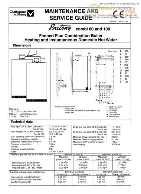
-=G vAA MAINTENANCE ANDSERVICE GUIDECCEdition et COMLEC 4/95Dimensionscombi 80 and 100Fanned Flue <strong>Combi</strong>nation BoilerHeating and Instantaneous Domestic Hot WaterJKLMNIBoiler outer case dimensions : I Safety valve outlet‘lue types: Height : 850 J Heating flow- Boiler width : 440 (minimum space required 450) K D.H.W. flow: 12 C 22 or C42: horizontal- Depth : 380L Gas supply:32xx: vertical concentricM Cold water inletN Heating returnTechnical dataHeat input C/H & DHW <strong>Combi</strong> 80 : 11.73 to 28.70 kW DHW flow rate at @ 30°C <strong>Combi</strong> 80 : 11.1 I/min<strong>Combi</strong> 100 : 15.43 to 34.57 kW <strong>Combi</strong> 100 : 13.4 I/minHeat output C/H & DHW <strong>Combi</strong> 80 : 9.5 to 23.25 kW DHW flow rate at @ 35°C <strong>Combi</strong> 80 : 9.54 I/min<strong>Combi</strong> 100 : 12.5 to 28 kW <strong>Combi</strong> 100 : 11.5 I/minMax. operating pressure C/H circuit : 2.5 bar Minimum DHW operating flow rate : 2 I/minExpansion vessel net capacity : 5.4 I Minimum DHW working pressure : 0.1 barExpansion vessel initial pressure : 0.7 bar Maximum DHW working pressure : 10 barElectrical consumption : 15ow Gas category : II 2E+ 3+Voltage230 vElectrical protection indexIP24Fuses : 2Aand 1.25ANominal gas flow rate at 15°C and 1013 mbar BRITONY <strong>Combi</strong> 80 BRITONY <strong>Combi</strong> 100Maximum Minimum Maximum Minimumpower 23.25 kW power 9.5 kW power 28.2 kW power 12.5 kW-Natural gas ( G 20) at 20 mbar 2.74 m3/h 1.22 m3/h 3.34 m3/h 1.57 m3/h-Butane gas ( G 30 ) at 28 mbar 2.04 kg/h 0.91 kg/h 2.45 kg/h 1.17 kg/h-Propane gas (G 31 ) at 37 mbar 2.00 kg/h 0.89 kg/h 2.42 kg/h 1.15 kg/hInjectors and gas valves seat diameter BRITONY <strong>Combi</strong> 80 BRITONY <strong>Combi</strong> 100Natural qas Butane or Propane Natural qas 1 Butane or Propane-Blue solenoid restrictor diameter 2.40 mm 1.74 mm 2.80 mm 1.90 mm-Black solenoid restrictor diameter 4.25 mm 5.00 mm 5.20 mm 3.80 mm-Manifold injectors (16) 1.23 mm 0.72 mm 1.26 mm 0.76 mm
Pump and expanssionvessel characteristicsHauteurmanomemquembar135 I,71321 1 ,I0 DPbd100 200 300 400 5OD 600 700 800 utl 0313I,31 = by-pass closed0,720 50 100 150 200 250 c (I)2 = by-pass openHead available / flowNote : The system initial pressure should be over the following value :System static height (in metre) + 0.7 = Initial pressure (in bar)10Componentslocation1. CH Flow isolating valve2. DHW outlet3. Gas service tap4. Water service tap5. CH Return isolating valve7. Pressure relief valve8. Chassis9. Connecting tails (x 5)83 4 95 710. Steel chassis complete with expansionJesse111. Sealed chamber12. Expansion vessel (not visible)13. Overheat thermostat14. Electrical box15.Three position selector switch16. User’s guide17. Heating flow temperature adjustment18. CH pressure gauge20. Green indicator - Power ON21. Orange indicator - Burner ON?2. Red indicator - Lock out/flame failure?3. Reset button24. Multigas burner comprising: 39. Combustion chamber made of-25. 16 burner head aluminium coated steel with 4 cera--26. Manifold mic fibre panels to insure heat insu--27. 2 Ignition electrode lation-28. lonization electrode 40. Copper main exchanger29. Gas section comprising: 41. Stainless steel secondary plate-30. Security valve (grey) exchanger-31. l/3 gas stage (blue) 42. Three way valve-32. 2/3 gas stage (black) 43. connecting bracket33. Right hydraulic assy 44. DHW flowstat34. Left hydraulic assy 45. Heating flowstat35. Single speed pump 46. Flue hood36. Air separator 47. Adjustable by-pass37. Heating thermistor 49. Air Pressure switch38. DHW thermistor 50. 45” elbow comprising venturi51. Fan2
WNCTIONINGthe gas service tap is opened at the gasmeter and50 pressure in central heating system is above 0.7bar and below 2.5 bar with the pressure gauge0 (8).3) Open the gas tap (3) by turning from right to left. 04) The boiler is now ready to use.1) Turn selector switch (15) to position flf . The green “poweron” indicator 0 (20) will light.‘9 0 ‘3 0 x3 Heating and Hot Water2) Turn on a hot water tap, the orange “burner on” indicator @(21) will light and the water will become hot.‘3 ‘3 0 ,3 ‘3 1) Turn selector switch (15) to position 2 ‘1111. The green“power on” indicator 0 will light (20).3) If the room thermostat (if fitted), the boiler temperature control‘1111 and the clock (if fitted) are all calling for heat, the orangeBRITONY COMBI FUNCTIONALDIAGRAM12____A35Hot water mode3
“burner on” indicator 4 (21) will light andwater temperature is controlled by the hot shuts off the gas. The red lockout indicatethe heating will be on. water control thermistor 38 and the central bulb 0 22 will light.When there is a need for hot water while heating control thermistor (37). This SYS- The central heating flow temperature i:the heating is on, it is only necessary to turn tern anticipates the changes of temperatu- controlled by the central heating contraon a hot tap. The heating will be interrupted re in the secondary heat exchanger and thermistor (37). The boiler has been desimomentarily while the hot water is being ensures accurate temperature regulation. gned to minimise cycling and will not attempdelivered. The boiler will switch back autotorelight for at least 3 minutes after the boimatically to heating when the tap is turnedWhen the tap is closed the burner is extin- ler thermostat has been satisfied. When theOff.guished and the pump stops. The boiler room thermostat is satisfied the burner wilNote: If the boiler has been turned off for will now stay in the hot water mode for switch off and the pump will remain runningsome time the first attempt to light it may three minutes to maintain temperature to for a further 3 minutes before it too stops.ensure a fast response in the event of aresult in a lockout @ (22) . If this happenspress the reset button (23) and the boiler subsequent hot water demand. NBwill light.It is possible to override the 3 minute dela!Priority will be given to a demand for hot by pressing the RESET button (23).Domestic Hot Water Mode water. This will interrupt the central hea-To be able to supply hot water, the selector ting for the duration of hot water delivery. Lock out procedureswitch 15 must be in either on ,:’ orFlame disappearance :‘11112 position. This will be confirmed byCentral Heating Mode When the ionisation electrode (28) does nothe green indicator light 0 (20)To be able to supply heating, the selector detect flame presence. The orange indicateswitch (15) must be on ‘Ill1 c? position. lamp (21) extinguishes. A lighting cyckWhen a tap or shower is turned on, the flow This will be confirmed by the green indicastarts.If a flame is not detected before fseconds, the grey security solenoid (30) arkof mains water, above 2 litres per min., will tor light 0 (20).the blue i/3 solenoid (31) will close. Theactivate the DHW flow switch (44) andlock out red indicator (22) lights, the pumpallow the 3 way valve (42) to move to the When there is a demand for heating(35) runs and the 3 way valve (42) stays irDHW position. The pump can now circulate (either from the room thermostat or theIts position.primary water heated by the main heat clock) the pump starts. If the boiler tempe-After a few seconds, it will become possibkexchanger through the secondary heat rature control is calling for heat and primatoreset the boiler by pressing the reset butexchanger. ry flow rate over 4 Itr/min, the central ton (23).heating flow switch operates ailowing theThe first stage solenoid (31) (blue) and . Ignition sequence to begin. The first stage Overheat detection :security solenoid (30) (grey) open togethersolenoid (31) (blue) and security solenoid If an overheat is detected by the sensoto allow gas to the burner. The ignition(30) (grey) open together to allow gas to (13), the grey security solenoid (30) and thesequence begins and a continuous highspeed spark ignites the gas. As soon as a the burner. The ignition sequence begins blue i/3 (31) closes, the orange indicateflame is detected the orange indicator bulb and a continuous high speed spark ignites lamp (21) extinguishes. The ignitor is energih (21) will light and the second stage sole- the gas. As soon as a flame is detectedsed for 8 seconds and the red lockout indicator (22) ligths. If the burner cannot relighnoid (32) (black) opens to allow the full gas the orange indicator bulb b (21) will light.the boiler will go to lockout.rate. If a flame is not detected, after 8 After 45 seconds the second stage soleseconds,the security solenoid closes and noid (32) (black) opens to allow the fullshuts Off the gas. The red lockout indicator gas rate, lf a flame is not detected, after 8bulb @ (22) will light. The domestic hot seconds, the security solenoid closes andWIRINGrEiimiqPlug for main power and Roomthermostat connection1 2 3 4 5I4El1. Neutral2. Phase3. Room thermostat live4. Accelerator resistor5. Common for Accelerator and roomthermostat.
ELECTRICALI U”13.14.I4a.14b.I4c.l4d.I4e.I4f.149.18.27.28.30.31.32.35.37.38.$2.$4.$5.51.WIRING continuationDesignation Wiring colours-Overheat sensorBrown-Electrical box-Regulation PCB-IgniterRed, Black-Fuse 1.25 A-Fuse 2A-Power PCB-Room thermostat-Mains 230V 50 Hz-Pressure switch2: Black P: Orange1: White-Spark electrodesWhite-Ionisation probeWhite-Security solenoid (grey) Grey-2/3 gas stage solenoid (black) Black-l/3 gas stage solenoid (blue) Blue-Pump-C/H thermistorViolet-DHW thermistorGreen-3 way valve White, Yellow, Orange-DHW flow switchBrown-C/H flow switchRed-FanBrown. BlueREGULATIONTemperature regulation for both C/H andDHW circuits are controlled by 2 thermistors.The C/H knob allows the adjustmentDf temperature between 35 and 85°C. TheDHW temperature is limited to 60°C. DHWand C/H thermistors are identical andinterchangeable.Resistance value are-5000 Q at 25 “C-2631 Q at 40°C-620 52 at 80°C-255 Q at 11o”cFLOW SWITCHESIADJUSTMENTSON CONTROLThe following adjustments are available on the regulation PCB. Togain access to them, pivot down electrical box, remove the rearcover and the rear panel of electrical box, unplug connectors fromregulation PCB and pull it toward you.Heating output limitation :- Functioning without limitation plug C on “P MAX”- Functioning at l/3 gas rate only plug C on “P l/3”Burner functioning:- Regulation available 3/3, l/3, 0- Functioning at full gas rate onlyTo ensure continued efficient operation ofthe appliance, it is recommended that it ischecked and serviced as necessary atregular intervals. The frequency of servicingwill depend upon the particular installationcondition and usage, but ingeneral, once a year should be adequate.It is the law that any service work must becarried out by a competent person suchas your local Chaffoteaux Service Centre,British Gas or other CORGI registeredpersonnel in accordance with the currentGas Safety (Installation and Use)Regulations.ROUTINE SERVICINGplug D on “NOR”plug D on “TUR”- Check that the fan blades are clean.- Check, clean and replace components asnecessary.- Carry out combustion test utilising the tespoints in the flue turret.SUGGESTED SEQUENCE for SERVI-CINGBefore disconnecting or removing anyparts, isolate the gas and electricity supplies.Ensure that the appliance is cool.(for detail please see section on PartsRemoval and Replacement)1Flow in both D.H.W. and Heating circuitsare detected by 2 flow switches. A pistonwith a magnet at the top operates a REEDswitch. The piston is lifted by flow rateslisted below :Flow rate threshold :D.H.W. 120 I/h ?20 I/hC/H 250 I/h *20 I/hAIR PRESSURESWITCHThe air flow rate is detected by a pressuredifferential created by a venturi located inthe flue duct.ON thresholdOFF thresholdAP > 130 PaAP < 100 PaThe service schedule should includethe following operations:- Check the pressure in the system.- Check the correct operation of theappliance.- Check the correct operation of the gascontrols.- Check the functions of the safetycontrols.- Check combustion chamber insulationpanels for damage.- Clean the burner.- Clean the heat exchanger.- Check the burner manifold injectors.- Clean gas and water filters.- Check expansion vessel charge pressure.- Clean and check operation of safetyvalve.Additional Procedures that may benecessary:- Check burner pressure and gas flowrates.PreliminaryChecks- Remove outer case- Check the system pressure is at least0.7 bar cold- Check operation of l/3 and 2/3 solenoids- Check that the burner is extinguished full:when both solenoids are closed in bothDHW and C/H modes.- Test ionisation functions and check thatlockout occurs by turning off gas tap.-Whilst boiler is operating, check operatiorof primary flow switch by closing heatingflow valve and by pass screw (turn clockwise) noting the number of turns so that itmay be reset correctly.5
REMOVAL AND REPLACEMENT OF PARTS1efore removing appliance case, isolate 5. Ignition Electrodese gas and electrical supplies. Isolate boi- Carry out steps 1 and 2 as above. Hinger from the system and drain before remo- down electrical box by pressing retainingng any component in the waterways. tabs P on either side.nsure that the appliance is cool. Remove wiring cover C. Disconnect leadsfront panel as in steps 1 and 2. Disconnecthree pressure switch cables noting the1positions.1 = white cable connected to NC2 = black cable connected to NOOuter Caseandt free. When replacing, carefully locate ongs (B) on top edge of chassis.from spark generator. Loosen screws securingthe closure plate and remove. Removegrommet from base of sealed chamber.Remove screw securing electrode bracketand lift clear easing spade connectorsthrough the grommet. Reassemble in reverseorder, twisted together electrodes cableat least IO times to avoid electrical interference.6. Burner AssemblyCarry out steps 1,2, disconnect electrodesas mentionned in section 4 and 5. Removetwo screws securing burner assembly to theback panel of the boiler. Lift right hand backcorner first. Reassemble in reverse order.7. Gas SolenoidsDisconnect colour coded leads. Remove sixscrews. The solenoids are attached to theirbase plate. Lift clear taking care not to losethe three plungers and springs.Reassemble in reverse order replacing thecork gasket.CP = orange cable connected to CRemove screw securing the switch bracksto the chassis. Disconnect the samplin!tubes again noting their positioning (+ an-). Remove switch. Reassemble in reversorder.11. Pressure Switch VenturiCarry out steps 1, 2 and 8, as aboveDisconnect the sampling tubes and remave the screw securing the venturi to thlflue outlet. Remove venturi by the bottonof the 45” elbow. Reassemble in revelsorder.12. Drain down5 drain points are located on the boilerCombustion Chamber8. Fan Assemblyiscrew four self tapping screws securing Remove outer case and sealed chambers sealed chamber front panel and lift front panel (See Steps 1 and 2). Disconnecter top corner locating lugs. Unscrew four spade connectors noting positions. RemoveIf tapping screws to release combustion two screws securing the front of the faniamber front plate and lift clear. assembly and loosen screw on flue outlet.?assemble in reverse order.Twist fan assembly anticlockwise to disengagefrom flue outlet and lift clear.Burner ManifoldRe-assemble in the reverse order ensuringlrry out steps 1 and 2 as above. Remove that the wiring is re-connected correctly ando screws securing the closure plate and the screw on the flue outlet tightened.? remaining four screws to release themifold. Lift clear. Replace the manifold 9. Flue Hoodsket. Reassemble in reverse order. Carry out steps 1 and 2 as above. Removefan assembly as in step 8. Remove thethree screws securing the angled top of thehood to the chassis. Lift and remove takingcare not to snag the pressure switch cables.Ionisation Electrodestrry out steps 1 and 2 as above. Loosenrews securing the closure plate andnove. Disconnect the lead from the mainring loom. Remove screw securing elec-Ide to burner. Thread wire through grom-9 and lift clear. Reassemble in reverseder.Re-assemble in the reverse order ensuringthat the hood is located behind the combustionchamber rear panel.10. Pressure SwitchRemove outer case and sealed chamber(air sebarator)1 = DHW circuit drain point2 = Heating circuit drain point13. Water filters ( DHW and Heating)The DHW filter ensures a seal between theconnecting bracket and the pipe to theDHW flow switch. Drain the boiler as irstep 12. Unscrew the pipe nut and removethe clip on the hydraulic assy. Pull the pipetoward you and remove the water filterfrom its location.The C/H filter is located in the right hydraulit assembly. Remove the return pipe a:described previously and withdraw the fitter. Reassemble in reverse order.
toward you to remove. Reassemble in rever-14. Flow switchesse order.Drain boiler as in step 12. Disconnect theHelectrical plug, turn the top cover anti- 18. Pumpclockwise, remove the O-ring and the Drain boiler as in step 12. Pivot the electicalbrass piston. Reassemble in reverse order. box downwards. Open the electrical boxcover removing the 2 screws. Remove the15.3-Way valvepump plug from the power board and earthDrain boiler as in step 12. Remove the 3 plug from earth socket. Unscrew the nut (F)clips on the 3 way valve. Remove the clip of the return pipe from the volute. Removeon the exchanger flow pipe. Pull the pipedown then pull it out of the 3 way valve.Disconnect the plug from the motor.Unscrew the nut on the pipe between theconnecting bracket and the 3 way valveand pull it toward you. Rotate the 3 wayvalve body anti-clockwise to unclip it fromthe left hydraulic assembly.22. Spark generatorCarry out steps 1,2, and open the electrical16. Secondary heat exchangerbox cover as mentionned in step 5. UndoDrain both circuits of the boiler as in stepthe 4 screws of the electrical rear panel and12. Unscrew the 2 fixing screws (D) andremove it. Unplug electrodes wires, removeremove the DHW exchanger from the front.the ignitor connector from the PCB, removeearth plug from earth socket. Hang out theignitor. Reassemble in reverse order.23. Power boardCarry out steps 1, 2, and open the electricalbox cover as mentionned in step 5. Undothe 4 screws of the electrical rear panel andthe clip (G) on the pump volute and pullremove it. Unplug all cables from the PCB,pump toward you. Reassemble in reverseremove earth plug from earth socket. Hangorder.out the power board. Reassemble in reverseorder.19. Pressure relief valveThe pressure relief valve can be servicedfrom the front of the appliance. Drain the boilerfirst, undo the retaining screw and pullout the valve.Reassemble in reverse order.24. Control boardPull out plastic knob from the front paneland proceed as step 23. Reassemble inreverse order.Prior to reassembly, check that the 4 gas- 20. Thermistorskets are correctly positioned. The heat Drain the boiler as step 12. Disconnect theexchanger is so designed that it cannot be plug, remove the retaining clip pull the therremountedincorrectly.mistor out. Reassemble in reverse order.38 = DHW thermistor17. Main heat exchanger37 = Heating thermistorCarry out steps 1 and 2 as above. Drainboiler as in step 12. Remove the 2 clips (E)located on return and flow pipes and pull3825. Expansion vesselRemove the casing as step 1 and drain theboiler as step 12 above. Unscrew theconnecting tails nuts and lift out the boilerfrom the wall. Place it on a side on the floor.Remove the expansion vessel bracketretaining screws, disconnect the pipe fromthe vessel and pull ti toward you.Reassemble in reverse order.37them downwards.Pull the main exchanger21. Safety thermostatRemove the casing as step 1 and hingedown the electrical box as step 5.Disconnect the 2 cables, pull out the sensorwith the clip (13). Reassemble in reverseorder.7
FAULT FINDING CHART Part 1.-Check mains electrical connection-Check internal fuses-Check connection between the 2PCBSNoOkYes- OkPress the reset buttonDoes the red LEDIhght ?1 NoI1 PLEASE CHECK THE FOLLOWING POINTS CAREFULLY BEFORE GOINGTHROUGH THE FAULT FINDING CHART-Gas pressure-Electric mains-Minimum water pressure in the heating circuit (over 0.8 bar)-All isolating valves have been opened-Boiler air vented-Minimum domestic hot water flow of 2 I/min-Check that the heating filter is clear.Check or replace the DWH flowswitchDoes the pump run 11Replace DHW flowswitchDraw off Domestic Hot water.I , ,Check DHW flow switch Does the pump run ? Does the fan run ?operationIy&3& “--IRelease pump rotorCheck or replace main or secondaryheat exchangers They could be Lot_..“-. ~ ..“.. ,,. .,,- -.iler11fully scaled.-Id 1Replace heating thermistorCheck heatingthermistorOk-Replace pressure swtch\ Jswitch continuitybetween P and 2Replace spark generator or ignitionelectrods assembly a go~~~o~~~~o 1 1I& NoReplace Driver or control PCB IReplace pressure switchCheck air pressureswitch continuitybetween P and 1Replace driver or control PCBNoReplace fan assemblyI
FAULT FINDING CHART Part 2Replace control PCB because orangeLED is deffectiveDoes the orange LEDlight ?Does the DHWtemperature rise ?NoF IWait until the temperaturebecomes stable.JDoes DHW temperaturerise over 7o”C?NoStop water draw offNoReplace control or driver PCBDoes the red LEDlight 1Check if an overheat occur or replaceoverheat sensorYesDoes overheat contactclose ?Replace DHW thermistorPress the reset buttonDoes the heating outletpipe temperature we ?Replace control PCBDoes the orange LEDlight ?Replace driver PCBDo the gas solendidsenergise 1Yes+YReplace the DHW heat exchangerReplace the 3 way valvecvi+YesReplace gas solenoidsIs there a gas pressureat manifold ?Replace electrode assemblyYesCheck the ionizationelectrodehot then rotate the heating controlknob anticlockwise to minimumOkIReplace driver PC6IReplace control PCBDoes the orange LEDlight ?I1 NoThe boiler is OKco
SHORT LIST104---B411572505 811 39805607938532615560(ey no Description BRITONY COMBI 80 BRITONY COMBI 100GC N” Manf. Pt. N” G.C. N” Manf. Pt. N”104 OVERHEAT THERMOSTAT 100°C 2;7$831010572 277783 1010572110 IGNITION ELECTRODE ASSY 277788 1002801 277788 1002801111 IONIZATION ELECTRODE 277789 1002802 277789 1002802113 HEAT EXCHANGER 277790 1010017 1011136206 FAN ASSY 277804 1010212 1003011216 PRESSURE SWITCH KIT 277808 81725 277808 81725411 SOLENOID VALVE KIT 277812 81432 277812 81432505 THREE-WAY VALVE 277833 1010000 277833 1010000514 WATER/WATER HEAT EXCHANGER 277836 1002540 1011164532 WATER THROTTLE HEAD ASSY 277846 81471 277846 81471553 WATER FILTER 277854 1007727 277854 1007727560 AIR SEPARATOR HEAD ASSY 277857 1002653 277857 1002653572 PUMP 1 SPEED 240V 277862 1010774 277862 1010774605 CONNECTOR 277872 1010349 277872 1010349607 IGNITER 379075 1002105.20 379075 1002105.20615 PRINTED CIRCUIT BOARD OF POWER 277880 1010592 277880 1010592616 PRINTED CIRCUIT BOARD OF REGULATION 277881 1010047 277881 1010047627 FUSE 250V 2A - TEMPORIZED 277883 1003456 277883 1003456629 FUSE 250V 1.25A - TEMPORIZED 277884 1003635 277884 1003635805 PRESSURE GAUGE 1012561 1012561811 BLACK KNOB 1011699 1011699922 TAP HEAD ASSY 366937 67704 366937 67704938 PRESSURE RELIEF VALVE 277770 76584 277770 76584Chaffoteaux et Maury are continuously improving their products and therefore reserve the right to change specifications withoutprior notice and accepts no liability for any errors or omission in the information contained in this document.627d62940 Chaffoteaux et Maury 19968a:6WizChaffoteaux et Maury Ltd 2QTrench LockTrenchaTelford -7EiShropshireTFI 4SZ : r:Tel: 01952 222727Fax: 01952 243493
ESP035