LED Digital Indicator and Bargraph Controller 264-DT Series
LED Digital Indicator and Bargraph Controller 264-DT Series
LED Digital Indicator and Bargraph Controller 264-DT Series

Create successful ePaper yourself
Turn your PDF publications into a flip-book with our unique Google optimized e-Paper software.
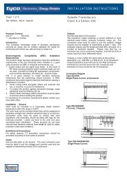
INSTALLATION INSTRUCTIONSPage 1 of 3Ref: IW<strong>264</strong><strong>DT</strong> – Rev 4 – Sept 02IntroductionThe <strong>264</strong>-<strong>DT</strong> range offers a 101/<strong>LED</strong>-<strong>Bargraph</strong> displaywith the added benefit of 4 or 3½ digit display. Thiscombination allows for both accurate instantaneousmeasurement <strong>and</strong> trend indication.InstallationThe units should be mounted in a reasonably stableambient temperature within the range 0 to 60°C. Theunit should not be mounted where it will be subjected toexcessive sunlight; vibration should be kept to aminimum. Connection wires should be sized to complywith local regulations <strong>and</strong> should preferably be fitted withtags for the terminals provided. Labels are fixed to theunit <strong>and</strong> carry connection information, <strong>and</strong> data includinginput voltage, input current, supply <strong>and</strong> applications asappropriate. These products do not have internal fusestherefore external fuses must be used for safetyprotection under fault conditions.Typical ApplicationsThe ease of on site programming allows for the use of<strong>264</strong>-<strong>DT</strong> series in a wide variety of applications such asProcess Control, Water Treatments, Power Generation,Control Panels <strong>and</strong> Switchgear Monitoring Systems.Assembly of Partswindows for heat radiation top <strong>and</strong> bottom(Clearance of 15cm maintained above <strong>and</strong> below)Acrylic cover Scale plateData LabelNote:<strong>264</strong>-<strong>DT</strong>V does not have set points <strong>and</strong> therefore doesnot have HH, LL, H <strong>and</strong> L <strong>LED</strong>’s.<strong>264</strong>-<strong>DT</strong>T only has low <strong>and</strong> high setpoints, therefore,does not have HH <strong>and</strong> LL <strong>LED</strong>’s.Functions1. SCALINGSpan <strong>and</strong> zero on the digital display can be adjustede.g. offset zero. Span <strong>and</strong> zero on the <strong>Bargraph</strong>display cannot be adjusted.2. OVER SCALE DISPLAYThe over-range annunciator “Hi” will display <strong>and</strong>blink on the digital display when the input signalexceeds the span value. The under-range<strong>Digital</strong> <strong>Indicator</strong>s<strong>LED</strong> <strong>Digital</strong> <strong>Indicator</strong> &<strong>Bargraph</strong> <strong>Controller</strong> <strong>264</strong> <strong>DT</strong> <strong>Series</strong>annunciator “Lo” will display <strong>and</strong> blink on the digitaldisplay when the input is below the zero value.3. SETPOINT PROGRAMMINGThe setpoints programming can be changed to suitthe desired positions (Hi/Lo or HiHi/LoLo) any valuebetween zero <strong>and</strong> span can be selected. If aninvalid value is entered, the processor will select thesetpoint position “OFF”. The setpoints must beprogrammed as HiHi > Hi <strong>and</strong> Hi > Lo <strong>and</strong> Lo>LoLo.4. ALARM OUTPUT DELAY FOR EACHSETPOINTThe alarm delay time can be programmed between0 <strong>and</strong> 10 seconds at 1 second intervals.5. RELAY HYSTERESISThe Hysteresis is to 1% of total scale, <strong>and</strong> notprogrammable.For programming instructions see overleaf.Fusing <strong>and</strong> connections1. This unit must be fitted with external fuses involtage <strong>and</strong> auxiliary supply lines.2. Voltage input lines must be fused with a quick blowfuse 1A maximum.3. Auxiliary supply lines must be fused with a slowblow fuse rated 1A maximum.4. Choose fuses of a type <strong>and</strong> with a breakingcapacity appropriate to the supply <strong>and</strong> inaccordance with local regulations.5. Where fitted, CT secondaries must be grounded inaccordance with local regulations.Warning• During normal operation, voltages hazardous to lifemay be present at some of the terminals of this unit.Installation <strong>and</strong> servicing should be performed onlyby qualified, properly trained personnel' abiding bylocal regulations. Ensure all supplies are deenergisedbefore attempting connection or otherprocedures.• Terminals should not be user accessible afterinstallation <strong>and</strong> external installation provisions mustbe sufficient to prevent hazards under faultconditions.• Never open circuit the secondary winding of anenergised current transformer.Screw torqueMain terminal screws should be tightened to 1.35Nm or1.0 ft/lbf only. Detachable terminal connector screwsshould be tightened to 0.9Nm or 0.7 ft/lbf only. Wherefitted, terminal covers are held in place by miniature selftapping screws into plastic. These screws should betightened by h<strong>and</strong> only, sufficiently to secure the terminalcover <strong>and</strong> prevent it vibrating.Electromagnetic CompatibilityThis unit has been designed to provide protection againstEM (electro-magnetic) interference in line withrequirements of EU <strong>and</strong> other regulations. Precautionsnecessary to provide proper operation of this <strong>and</strong>adjacent equipment will be installation dependent <strong>and</strong> sothe following can only be general guidance:-
Page 2 of 3Ref: IW<strong>264</strong><strong>DT</strong> – Rev 4 – Sept 02INSTALLATION INSTRUCTIONS<strong>Digital</strong> <strong>Indicator</strong>s<strong>LED</strong> <strong>Digital</strong> <strong>Indicator</strong> &<strong>Bargraph</strong> <strong>Controller</strong> – <strong>264</strong> <strong>DT</strong> <strong>Series</strong>• Avoid routing wiring to this unit alongside cables <strong>and</strong>products that are, or could be, a source ofinterference.• The auxiliary supply to the unit should not be subjectto excessive interference. In some cases, a supplyline filter may be required.• To protect the product against incorrect operation orpermanent damage, surge transients must becontrolled. It is good EMC practice to suppressdifferential surges to 2kV or less at the source. Theunit has been designed to automatically recoverfrom typical transients, however in extremecircumstances it may be necessary to temporarilydisconnect the auxiliary supply for a period ofgreater than 5 seconds to restore correct operation.• Screened communication <strong>and</strong> small signal leads arerecommended <strong>and</strong> may be required. These <strong>and</strong>other connecting leads may require the fitting of RFsuppression components, such as ferrite absorbers,line filters etc., if RF fields cause problems.It is good practice to install sensitive electronicinstruments that are performing critical functions in EMCenclosures that protect against electrical interferencecausing a disturbance in function.Programming InstructionsAll types of <strong>264</strong>-<strong>DT</strong> have the same operating controlbuttons:-M = Mode S = Store▲ = Up ▼ = DownThe annunciator <strong>LED</strong>’s on the right h<strong>and</strong> display are asfollows <strong>and</strong> flash when that particular parameter is beingprogrammed.Z = Zero <strong>LED</strong>P = Decimal point <strong>LED</strong>S = Span <strong>LED</strong>L = Low relay <strong>LED</strong> ) <strong>264</strong>-<strong>DT</strong>T )H = High relay <strong>LED</strong> ) )HH = High High relay <strong>LED</strong> ) <strong>264</strong>-<strong>DT</strong>FLL = Low Low relay <strong>LED</strong> )Programming <strong>264</strong>-<strong>DT</strong>1. To zero 4 digit displayPress M ➔ Z <strong>LED</strong> flashes ▲ or ▼ to give 0000.Press S to store. Note, offset zero readings arepossible ▲ ▼ until reading required is displayed.Press S to store.2. Decimal PointPress M ➔ P <strong>LED</strong> flashes ▲ or ▼ to achievedesired reading 0000, or 0.000, 00.00 or 000.Press S to store.3. Span for <strong>Digital</strong> DisplayInject full-scale input signal. Press M ➔ until S<strong>LED</strong> flashes. Then ▲ or ▼ until desired valueis shown on digital display, i.e., 4 digit 999931/2 1999 or any value between 0 <strong>and</strong> 9999 canbe programmed to correspond with the full scaleinput signal. Desired reading is stored bypressing S to store.4. <strong>Digital</strong> Filtering (average sensing)Periods of 1, 2, 4, 8 or 16 can be selected asfollows. Press M ➔ until P <strong>LED</strong> flashes ▲ ▼press simultaneously. The display will show A16, by pressing ▲ or ▼ 16, 8, 4 etc will show.Once the desired value is reached, press S tostore.5. Relay Programming <strong>264</strong>-<strong>DT</strong>T <strong>and</strong> <strong>DT</strong>F onlyLow setpoint M ➔ until L <strong>LED</strong> flashes ▲ or ▼until desired trip point value is reached. Press Sto store. High setpoint M ➔ H <strong>LED</strong> flashes thenrepeat as above. On <strong>264</strong>-<strong>DT</strong>F 4 setpoints LL isprogrammed before L <strong>and</strong> HH before H.Programming as above.6. Time delay setting for relays <strong>264</strong><strong>DT</strong>T <strong>and</strong> <strong>DT</strong>FonlyLow setpoint M ➔ until L <strong>LED</strong> flashes ▲ ▼pressed simultaneously. Display will show d Oby ▲ or ▼ a value between 1 <strong>and</strong> 10 secondscan be programmed. Once desired value isshown press S to store. LL, H <strong>and</strong> HH relaysare programmed as above.When a mode button is pressed an annunciator <strong>LED</strong>flashes indicating that function can be altered bypressing the up or down buttons. Once the desiredparameter is reached press the store button to store theparameter.The Information contained in these installation instructions is for use only by installers trained to make electrical power installations <strong>and</strong> is intended to describe thecorrect method of installation for this product. However, Tyco Electronics has no control over the field conditions, which influence product installation.It is the user's responsibility to determine the suitability of the installation method in the user's field conditions. Tyco Electronics' only obligations are those in TycoElectronics' st<strong>and</strong>ard Conditions of Sale for this product <strong>and</strong> in no case will Tyco Electronics be liable for any other incidental, indirect or consequential damagesarising from the use or misuse of the products. Crompton is a trade mark.Tyco Electronics UK LimitedCrompton InstrumentsFreebournes Road, Witham, Essex, CM8 3AH, UKPhone: +44 1376 509 509 Fax: +44 1376 509 511http://energy.tycoelectronics.com
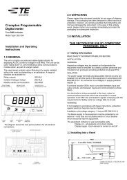
Page 3 of 3Ref: IW<strong>264</strong><strong>DT</strong> – Rev 4 – Sept 02INSTALLATION INSTRUCTIONS<strong>Digital</strong> <strong>Indicator</strong>s<strong>LED</strong> <strong>Digital</strong> <strong>Indicator</strong> &<strong>Bargraph</strong> <strong>Controller</strong> – <strong>264</strong> <strong>DT</strong> <strong>Series</strong>Programming GuidePanel Cutout DimensionFor single mounting for stacked mounting (horizontal)Mode <strong>LED</strong>Choosing Flashing Value Setting <strong>LED</strong> offHH Setting M HH ▲ ▼ SET HH SettingFinishedH Setting M H ▲ ▼ SET HSettingFinishedL Setting M L ▲ ▼ SET L SettingFinishedLL Setting M LL ▲ ▼ SET LL SettingFinishedZeroAdjustment M Z ▲ ▼ SET ZAdjustmentFinishedSpanAdjustment M S ▲ ▼ SET SAdjustmentFinishedDecimalPoint M P ▲ ▼ SET PAdjustmentFinished<strong>Digital</strong>Filtering M P ▲ ▼ SET PAdjustmentFinished simultaneouslyRelay TimeDelay M L,LL ▲ ▼ SET L,LLAdjustmentH,HHH,HHFinished simultaneously2 mounting plates are supplies in the packing box. Install asshown.Remove top <strong>and</strong> bottom lens clip by gently pulling forward.Turn the top <strong>and</strong> bottom mounting screws clockwise, this willlock the metal fitting against the back of the panel. Turningthe mounting screws anticlockwise will release the meter.MetalFittingClearances of 15cm must be maintained above <strong>and</strong> belowany meter. Failure to ensure correct clearance can causeoverheating <strong>and</strong> damage to the meter. With top <strong>and</strong> bottomlens clip removed, the clear cover <strong>and</strong> scale plate may beremoved.The Information contained in these installation instructions is for use only by installers trained to make electrical power installations <strong>and</strong> is intended to describe thecorrect method of installation for this product. However, Tyco Electronics has no control over the field conditions, which influence product installation.It is the user's responsibility to determine the suitability of the installation method in the user's field conditions. Tyco Electronics' only obligations are those in TycoElectronics' st<strong>and</strong>ard Conditions of Sale for this product <strong>and</strong> in no case will Tyco Electronics be liable for any other incidental, indirect or consequential damagesarising from the use or misuse of the products. Crompton is a trade mark.Tyco Electronics UK LimitedCrompton InstrumentsFreebournes Road, Witham, Essex, CM8 3AH, UKPhone: +44 1376 509 509 Fax: +44 1376 509 511http://energy.tycoelectronics.com