279161-34452-8230 LWZ 170-270-plus_GB.indd - Stiebel Eltron
279161-34452-8230 LWZ 170-270-plus_GB.indd - Stiebel Eltron
279161-34452-8230 LWZ 170-270-plus_GB.indd - Stiebel Eltron

Create successful ePaper yourself
Turn your PDF publications into a flip-book with our unique Google optimized e-Paper software.
Operating and installation instructionsCentral ventilation unit» <strong>LWZ</strong> <strong>170</strong>» <strong>LWZ</strong> <strong>170</strong> <strong>plus</strong>» <strong>LWZ</strong> <strong>270</strong>» <strong>LWZ</strong> <strong>270</strong> <strong>plus</strong><strong>279161</strong>
Content1. Operating instructions forusers and contractors 31.1 Equipment description 31.2 Particular features of the <strong>LWZ</strong>...<strong>plus</strong> 41.3 User interface 51.4 Operation 51.5 Maintenance and cleaning 6Symbols used in these instructionsObserve the following safety instructions:iPlease note: Warning about possibledangersNote: Important information2. Installation instructions forcontractors 72.1 Specification 72.2 Installation 82.3 Installation on the air side 92.4 Electrical connection 102.5 Frost protection 102.6 Settings 13Commissioning report 162.7 Fault analysis 162.8 Maintenance and cleaning 173. Environment and recycling 184. Customer service and warranty 19
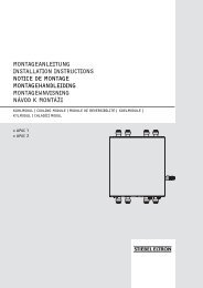
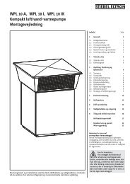
1. Operating instructions for users and contractors1.1 Equipment description1.1.1 GeneralThe <strong>LWZ</strong> <strong>170</strong>/<strong>270</strong>..<strong>plus</strong> can recover up to90 % of the latent energy in extract air. Thisis made possible by the use of new types ofcountercurrent heat exchangers. The air flowrate is regulated independently by two energysavingDC fans. This makes the <strong>LWZ</strong> <strong>170</strong>/<strong>270</strong>..<strong>plus</strong> a particularly powerful and highly efficientcentral unit for ventilating several rooms.The <strong>plus</strong> version is equipped with an integralbypass damper that channels cool ventilationair into rooms on hot summer nights.1.1.2 Description of functionsA central control unit safeguards the reliableequipment operation and minimum energyconsumption whilst maintaining maximumcomfort. It ensures that the selected set airflow rates remain constant.The <strong>LWZ</strong> <strong>170</strong>/<strong>270</strong>..<strong>plus</strong> is equipped with auser interface with display. That enables aninfinitely variable adjustment of the air flowrate as well as the scanning of operating detailson the display, without requiring the device tobe opened.Settings in the program of the centralcontroller can be called up and modified atthe user interface.1.1.4 Shutting the equipment downEven during longer periods away from home,it is recommended that the equipment shouldbe allowed, via the remote control, to runat switch position 1. Should the equipment,nevertheless, be switched off for longerperiods, pull its power supply plug from thesocket. Prior to this disconnection, switch OFFthe device via the user interface.1.1.5 Incorrect operationNever– use extract air loaded with grease, explosivegases, dust or adhesive aerosols– install the unit outdoors– connect cooker hoods and dryer exhauststo the ventilation system.Only qualified contractors are permitted towork on the equipment. Never adjust theventilation and extract air valves inside therooms. These have been adjusted duringcommissioning. Never make any modificationsto the internal equipment electrics or controls.Trouble-free operation can only be ensuredwith a closed filter door.Function diagram1.1.6 Regulations and standardsDIN 18017 - Ventilation of bathrooms andflush toiletsDIN 1946 T6 E - Ventilation and airconditioning, domestic ventilationDIN 2088 - Domestic ventilation equipmentVDI 2087 - Air ducts [or local regulations]Relevant Building RegulationsImportant informationPlease note: The ventilation devicemust only be installed andmaintained by qualified contractors.Operating and installationinstructionsNote: Keep these operating andiinstallation instructions safely andpass them on to any new user, should theequipment change hands, and let yourcontractor check their content inconjunction with any maintenance andrepair work.At a glance• Switching the device ON and OFF• Displaying the fan stage and theair flow rate• Infinitely variable flow rate selection• Scanning temperatures and status• Fault display• Optionally with integral bypass(<strong>plus</strong> version)1.1.3 FunctionThe <strong>LWZ</strong> <strong>170</strong>/<strong>270</strong> central ventilation unituses two fans and separate ducts to draw,respectively via individual filter mats, outsideair into the building and extract air fromrooms that are subject to odour or humidityloads (kitchen, bathroom, toilet, conservatory).Both air streams are routed via acountercurrent heat exchanger where theoutside air absorbs energy that is transferredfrom the extract air. The airways are separatedfrom each other, thereby preventing odoursfrom being transferred between outsideair and extract air, subject to the correctoperation of the equipment.The heated fresh air is blown into theaccommodation via suitable air ducts andadjustable vents (available as accessories),whilst the cooled extract air is expelledthrough the roof or through a wall.14567891011112111098ConnectorRoom air temperature sensorCountercurrent heat exchangerExtract air filterOutside air filterOutside air temperature sensorCondensate drain connectionExtractor fanUser interfaceControl PCBOutside air fanCable entries7123456Outside air / ventilation airExtract air / expelled airC26_04_01_0190
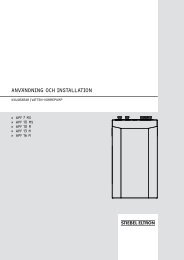
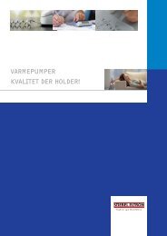
1.2 Particular features ofthe <strong>LWZ</strong>...<strong>plus</strong>The <strong>LWZ</strong>...<strong>plus</strong> contains an integral bypassmodule with one N/O and one N/C bypassdamper. This module reduces the heat transferat specific temperatures in summer.When the bypass damper is closed, outsideair flows through the <strong>LWZ</strong> heat exchanger.With opening the bypass damper, the heatexchanger is closed on its ventilation airside. This channels the outside air throughthe bypass, in other words past the heatexchanger; hence it acts as ventilation air forthe dwelling.Consequently, no heat is transferred to theventilation air. Essentially, this function is utilisedin summer. During the day, the heat exchangerensures that the house is not overheated.At night, when the outside temperature islower than the room temperature, the bypassdamper opens, and the cool outside air isdirectly channelled into the living space.3121Bypass damperBypass damper controlClosing facilityC26_04_01_0220General function (schematic diagram)Outside air / ventilation airExtract air / expelled airBypass damper closedBypass damper openABCDHeat exchangerBypass damperBypass module<strong>LWZ</strong> <strong>170</strong>/<strong>270</strong>C26_04_01_0225
1.3 User interface1.4 OperationThe <strong>LWZ</strong> <strong>170</strong>/<strong>270</strong>..<strong>plus</strong> units are equippedwith a user interface with LED.Settings in the program of the centralcontroller can be called up and modified atthis user interface.The user interface is equipped with four keysand one display.The left area of the display shows the fanoperation or the parameter type. The rightarea displays the current value, e.g. air volume.Example:The display now indicates that the deviceis operating at stage 1 at an air volume of100 m 3 /h.12145DisplayKey “OK” (operate, finished,reset filter display)Increase parameter value keyFunction keyReduce parameter value key345C26_04_01_0194The remote control enables the operationof the <strong>LWZ</strong> between stage 1 and 3. Forthis, observe the operating and installationinstructions of the respective remote control.Stage 2 should be treated as the standardventilation, stage 3 as the demand ventilation,e.g. party stage (quick ventilation) and stage1 as the minimum setting (for example, whenyou are away).The user control at the device is limited toswitching the device ON and OFF.Your contractor has set the <strong>LWZ</strong> specificallyto suit the conditions of your home and toyour personal requirements. Never changeany system-specific settings via the userinterface.StartingPlug the power supply cableinto the socket and startthe device by simultaneouslypressing programming keys“OK” and “+”.(Only possible if the devicewas switched off with theprogram keys).On the display, the first figurerepresents the position of thethree-stage switch.3 secondsThe parameters listed in the table can becalled up with keys “+” and “–”. The displayreverts to the standard operating modedisplay if no key is pressed for 5 minutes. Key“+” enables you to scroll through the menu.Key “–” only enables the return to parameter1. Set values cannot be adjusted in this menu.C26_04_01_0196StoppingStop the device bysimultaneouslypressing the program keys“OK” and “–”. The displayshows OFF.Pull the power supply plugfrom the socket; the device isnow disconnected from thepower supply.3 secondsParameterDisplay(example)Description1 1.100 Current setting/extract air volume [m 3 /h]2 C 0 Message code operating mode C0 = No messageC3 = The ventilation air fan runs in the operating mode ‘constant pressure’C6 = The extract air fan runs in the operating mode ‘constant pressure’C7 = Correction maximum air volume3 bP.1 Bypass status(only for integral bypass)Note0 = Bypass damper closed / 1 = Bypass damper automatic /2 = Minimum ventilation air4 tP.9 Outside air temperature [°C] For temperatures below minus (< 0 °C) display tP.9.5 tS.21 Extract air temperature [°C]6 In.0 No function
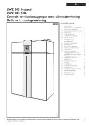
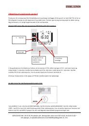
1.5 Maintenance andcleaningMaintenance by the user is limited to theregular cleaning and replacing of the filter.The filter will only need cleaning when therespective letter combination “FIL” is shownon the display, but should be cleaned atleast annually. Never operate the equipmentwithout the filter.A contractor should check or clean the heatexchanger, the condensate drain and the fansat least once a year.Cleaning and replacing the filter1 Switch OFF the device via the userinterface. For this, press and holddown simultaneously “OK” and “–” for3 seconds.2 Open the filter door. This enables you topull out both filters and check them forcontamination.Replace the filters if they are heavilysoiled (solid layer of dust on the top ofthe filter mat). Clean the filters with avacuum cleaner, if they are only lightlysoiled. These filters cannot be washed.Washing would mat the fabric, leaving toolittle air to flow through the filter.3 After inserting the filters, close the filterdoor and restart the device via the userinterface (simultaneously press both“OK” and “+” for 3 seconds).Please note: When re-inserting thefilters ensure that the solid, finepored side is turned towards the l.h. side,i.e. towards the heat exchanger.4 Reset the filter status display by pressing“OK” (1 second).The display flashes briefly as confirmationthat the filter status has been reset. Thenthe operating mode display “operation”will be shown again.Please note: All other work on theequipment must only be carried outby qualified contractors. Never adjust theventilation and extract air valves inside therooms. These have been adjusted duringcommissioning. Never make anymodifications to the internal equipmentelectrics or controls. Trouble-freeoperation can only be ensured with aclosed filter door.Filter change1324C26_04_01_0222
2. Installation instructions for contractors2.1 Specification(The details on the equipment type plate apply)Type <strong>LWZ</strong> <strong>170</strong> (<strong>170</strong> <strong>plus</strong>) <strong>LWZ</strong> <strong>270</strong> (<strong>270</strong> <strong>plus</strong>)Part no: 22 12 34 (22 12 35) 22 12 36 (22 12 37)Voltage/Frequency V, Hz 1/N/PE ~ 230 V 50 Hz 1/N/PE ~ 230 V 50 HzMax. power consumption A 1.1 (1.17) 2.01 (2.08)Power consumption W 16 - 130 12 - 230Air volume flow m³/h 50 - 250 50 - 350Protection level to VDE IP 31 IP 31Externally available max. static pressure differential Pa 160 at 250 m 3 /h 160 at 350 m 3 /hMax. ambient temperature °C 60 60Filter class G 3 G 3Air duct connection DN 160 160PE condensate drain connection mm 13 13Height mm 602 602Width mm 675 675Depth mm 445 (525) 455 (535)Weight excl. packaging kg 31 (35) 31 (35)Sound pressure level tested 1 m from theunit in accordance with EN 255 T7dB(A) 28.5 at 100 m³/h, 40 Pa)38 at 150 m³/h, 80 Pa)46.5 at 225 m³/h, 160 Pa)33 at 100 m³/h, 40 Pa)43.5 at 200 m³/h, 80 Pa)51.5 at 300 m³/h, 160 Pa)AccessoriesPart no:Filter mat set; content: 10 pce. 16 09 50Remote control unit FEZ 18 53 58Remote control FEQ 18 98 00Three-stage switch 16 25 51All ventilation pipes, valves and similar equipment are also available from <strong>Stiebel</strong> <strong>Eltron</strong>.
2.2 InstallationTransportDetail XTo protect the equipment against damage, itmust be transported to the installation roominside its original packaging.GCPositioning the equipmentInstall the equipment in a suitable locationwhich is free from frost (as centrally aspossible to achieve the shortest possible airducts). For this, unscrew the top two Philipsscrews at the back of the device, and secureone of the two rails (G) to the device usingthe screws. Fit the other rail as a retainer tothe wall.Before securing the rail to the wall, ensurethat the wall is sound and strong enough tobear the weight of the device. Subject to wallstructure, use suitable rawl plugs and screwsto mount the rail to the wall. To preventsound transmission, use washers (D) and thechannel section (C) in accordance with detailX. Before mounting the device by hanging itinto the rail, fit the spacers (E) supplied to theback of the device.Fit the equipment so that it is level to ensurethat the condensate drains off properly.Ensure sufficient space for maintenance in frontof the equipment. Maintain a distance from theceiling of at least 250 mm. Maintain a minimumclearance towards the wall of 50 mm.DFI Ventilation airII Expelled airIII Extract airIV Outside airA Power supplyB Interface forremote controlC Condensate drainD Channel section (rubber)E Washer (rubber)F SpacerG RailsABEDimensions in mm( ) - Dim. = <strong>LWZ</strong> <strong>270</strong>...<strong>plus</strong>min. 10% slopeC26_04_01_0230Condensate drain connectionThe equipment is supplied with an angledcondensate connector and a condensate drainhose with an internal diameter of 13 mm anda length of 1500 mm. Insert the condensatedrain connector into the bottom of thedevice.For this, use PTFE tape on the connectorthread.You can adjust the condensate drainconnector, whilst tightening it, into its requiredposition.Note: Never kink the hose, to ensureithe condensate drains perfectly. Theslope must be at least 10%, and the devicemust be level.Condensate drainmin. 10% slopeAfter completing the installation, checkthe function, draining capability and watertightness of the condensate drain. For this,pour approx. 1 l of water into the condensatepan. The entire water volume must drain offswiftly.26_04_01_0192
2.3 Installation on the airsideThe installation is completed withcommercially available slip tubing and profiles.This installation material may be obtainedfrom <strong>Stiebel</strong> <strong>Eltron</strong>.During the installation, ensure that no metalswarf enters the pipe system. However, shouldthis occur, remove this debris, otherwise thefans may be damaged.Use thermally insulated pipes to construct theoutside air and expelled air ducts.Thermally insulate these pipelines, if they areconstructed from non-insulated pipes andprofiles.Where the ventilation air and extract air ductsare routed through unheated rooms, thermallyinsulate those too.Please note: Never connect cookerhoods and dryers to the ventilationsystem.SilencersGenerally, fit one silencer each in theventilation air and the extract air ductAdditional silencers are recommendedupstream of bedrooms and living rooms (or inrooms where noise should be kept down andwhere noise transmission should be avoided).If a room with a high noise level must beventilated, install additional silencers in theapproach to and the exit from such roomsto reduce sound transmission into adjacentrooms.Clean-out aperturesAir ducts must be checked and possiblycleaned at regular intervals. Releasing the airduct from the device or at the extract air andventilation air valves enables the inspectionand cleaning.External wall outletSupply fresh air from a location wherecontamination (dust, soot, odours, flue gas,expelled air) is as low as possible.When creating the external wall outlet ensure,that a “short circuit” between the fresh airinlet and air outlets is avoided. It would bepractical to use our external wall inlet andoutlet grille (part no: 07 18 32).Ventilation and extract air valvesVentilation and extract air valves for the livingspace are available for wall or ceiling mounting.During installation, ensure a thoroughventilation of the room.Overflow aperturesThe living rooms and bedrooms onlyreceive air, and the rooms loaded withodour and humidity only have air extracted.Consequently, fit interconnecting ventilationgrilles into adjoining doors or walls or increasethe air gap below a door to ≥ 8 mm, toensure an unrestricted air flow betweenrooms.Static Statischer pressure Druck [Pa] [Pa]Static Statischer pressure Druck [Pa] [Pa]Fan curve <strong>LWZ</strong> <strong>170</strong> (<strong>plus</strong>)Fan curve <strong>LWZ</strong> <strong>170</strong> (<strong>plus</strong>)Air Volumenstrom volume [m³/h] [m³/h]Air Volumenstrom volume [m³/h] [m³/h]Safety instructionsIf the dwelling contains combustion equipment(tiled stoves, fire places, wall mounted gasheaters, etc.), ensure that such combustionequipment is supplied with combustionair separate from the ventilation system(check with your local flue gas inspector,as requirements vary across regions andcountries).When operating a dryer or a cooker hoodthat extracts air, ensure also, that a sufficientlylarge air volume flow is supplied to thatequipment, independent of the ventilationequipment.max. characteristic curve for max. volume flowmax. characteristic curve for max. volume flowC26_04_01_0223C26_04_01_0224
2.4 Electrical connectionThe device is supplied fully wired, and shouldbe plugged into an easily accessible mainssocket.A 1 m long LV cable for the connection of aremote control is supplied with the device.Observe VDE 0100 [or local regulations] andthe regulations of your local power supplyutility.2.4.1 Remote control unit FEZThe FEZ remote control enables the selectionof one of the three preset air flow rate stages.The operating mode selector offers thefunctions: party, day/night, automatic andstandby (OFF). The programmable analogtime switch controls the changeover betweenday and night mode. An indicator signals therequirement for changing the air filter.2.4.1 Remote control FEQ (part no: 189800)The FEQ remote control enables the selectionof the three preset air flow rate stages.The operating mode selector offers thefunctions: party, standard/setback mode,automatic and standby (OFF).2.5 Frost protectionOn account of the high heat availability factor,low outside temperatures result in the outsideair being cooled down so severely that anycondensate that is created in the process mayfreeze.The frost monitoring ensures that the extractside of the heat exchanger cannot freezeup. This is achieved by the ventilation airflow and the extract air flow being broughtout of balance, subject to the outside airtemperature and the pressure drop in theheat exchanger. This effectively prevents theunit freezing up.The ventilation air fan may also, for shortperiods, be switched OFF at very low outsidetemperatures.The imbalance and the shutting down of theventilation air fan can be prevented by preheatingthe outside air through an electricpre-heater bank or by means of a ground heatexchanger.2.4.2 Three-stage switch (part no: 162551)The three-stage switch enables the selectionof the three preset air flow rate stages.The operating mode selector offers thefunctions: party, day and night mode.2.4.3 Installation of remote control unitsConnect the respective remote control,subject to the equipment-specific operatingand installation instructions or in line with theconnection diagram on pages 11 and 12, tothe equipment using the interface and theconnecting cable supplied.Please note: Route the LV cable ofthe remote control units and thepower supply cable of the ventilationdevice separately.10
Wiring diagram <strong>LWZ</strong> <strong>170</strong>, <strong>LWZ</strong> <strong>270</strong>DayOutOutDayDayABCDEFGHJThree-stage switchRemote control FEZRemote control FEQRoom temperature sensorControl PCBVentilation air fanExtractor fanOutside temperature sensorUser interfaceA1 brownA2 blueA3 green/yellowA4 blackA5 whiteA6 No. 1A7 No. 2A10 yellowC26_04_01_021511
Wiring diagram <strong>LWZ</strong> <strong>170</strong> <strong>plus</strong>, <strong>LWZ</strong> <strong>270</strong> <strong>plus</strong>DayOutOutDayDayABCDEFGHJKLMThree-stage switchRemote control FEZRemote control FEQRoom temperature sensorControl PCBVentilation air fanExtractor fanOutside temperature sensorUser interfaceDamper control, slide grilleDamper controlBypass damperBypass PCBA1 brownA2 blueA3 green/yellowA4 blackA5 whiteA6 No. 1A7 No. 2A10 yellowC26_04_01_021012
2.6 SettingsThe four keys on the user interface have thefollowing functions:• F Function key / parameter menuswitching ON and OFF• + Next parameter / increase value• – Last parameter / reduce value• OK Switching the settings menu ONand OFF / manually resetting faults /resetting the filter displayOther commands are issued by pressing thefollowing key combinations.• F & + (set), Confirm parameter value• F & – (reset), Resetting the parameterto the factory default..• OK & + (ON), Switch ON the device• OK & – (OFF), Switch OFF the deviceIn these operating and installation instructions,every operation using the function keys isshown as the respective key in invertedcommas and emboldened.Example: - press OK”2.6.1 Displaying selected valuesThis display shows as standard the current fanstage and the respectively selected extractair volume (operating mode). The fan stage(stage 1, 2 or 3) is shown on the l.h. side of thescreen and the extract air volume is shown tothe right of the full stop.In case of faults, the fault number is shown onthe display (see section 2.6 Fault analysis).abRemote control stageExtract air volume2.6.2 Calling-up selected valuesPressing “F” and “OK” simultaneously for3 seconds enables all available data to becalled up. However, values cannot be adjustedor modified in this menu.This menu always opens in parameter 7 (seethe following table). Key “+” enables the datato be called up, pressing “–” returns you toparameter 1.This menu is automatically cancelled if theNO key is activated for 5 minutes, when thedisplay shows the standard operating modeagain.Parameterno.Display(example)Description1 2.100 Current setting/extract air volume [m 3 /h]2 C 0 Message code operating mode C0 = No messageC3 = The ventilation air fan runs in the operating mode ‘constant pressure’C6 = The extract air fan runs in the operating mode ‘constant pressure’C7 = Correction maximum air volume3 bP.1 Bypass status (only for integral bypass) 0 = Bypass damper closed / 1 = Bypass damper automatic /2 = Minimum ventilation air4 tP.9 Outside air temperature [°C] For temperatures below minus (< 0 °C) display tP.9.5 tS.21 Extract air temperature [°C]6 In.0 No function7 u.156 Current ventilation air volume [m 3 /h]8u .156 Current extract air volume [m3 /h]9 t.180 Current pressure, ventilation air duct [Pa]10 A.180 Current pressure, extract air duct [Pa]11 u0.0 Frost protection status 0 = None, 1 t/m 4 = Pressure imbalance, 5 = Ventilation air fan OFFNote12 St.9 Expelled air temperature(sensor not provided as standard)13 Pt.18 Ventilation air temperature(sensor not provided as standard)[°C][°C]If not provided, St.75If not provided, Pt.7513
2.6.3 Adjusting the air volumeThe air volume of the <strong>LWZ</strong> <strong>170</strong>/<strong>270</strong>..<strong>plus</strong> forthe stages 1 to 3 are factory-set to 50, 100 and150 m³/h.Important:Stage 1: must always be lower than stage 2;Stage 2: must always be lower than stage 3;Stage 3: adjustable between 50 and 180 m³/h;The air volume of the higher stage isautomatically selected if one of the aboveconditions is not met.The air volume can be modified as follows(as example, the air volume for stage 3 isincreased from 150 to 180 m³/h):1. Press “F” for 3 secondsto activate the settingsmenu.2. Select the requiredparameter with “+”:U1 = stage 1U2 = stage 2U3 = stage 33. Press “OK” for 1 secondto display the value ofthe selected parameter.4. Keys “+” or “–” enablethe air flow rate to bechanged.5. The modified value can now:A be saved;B not be saved;C return to the factory default.A Simultaneously press“F” and “+” (first “F,”then “+”) to savethe modified value;the modified valuebegins to flash 3 x asconfirmation.Press “OK” to returnto the settings menu;if required, furthervalues can now bechanged (see steps2 to 5).B Press “OK” to returnto the settings menuwithout saving themodified value; thepreviously activevalue is maintained.If required, furthervalues can bemodified (seesteps 2 to 5).C Simultaneously press“F” and “–” to returnto the factory-set airflow rate. The factorysetting flashes 3 x asconfirmation.Press “OK” to returnto the settings menu;if required, furthervalues can nowbe changed (seesteps 2 to 5).2.6.4 Changing parameter settingsThese parameters must only be changed bya contractor, as changing these parametersettings can impair the correct function ofthe device.For factory settings, see the commissioning liston page 13.I 1 Pressure imbalanceThis enables the creation of a fixedpositive (+) or negative (-) pressure inthe house.Positive pressure imbalance (+):The extract air fan ventilates by a fixedvalue [m³/h] less than the ventilation air fan.Negative pressure imbalance (-):The ventilation air fan ventilates by afixed value [m³/h] less than the extractair fan.I 2 Remote control, open switching contact(night)This parameter determines which fanstage is activated by an open switchingcontact.I 4 Control cable 0 OFFThis parameter determines which fanstage will be activated with the controlcable OFF.I 5 Control cable 2 (day)This parameter determines which fanstage will be activated with the controlcable 2.I 6 Control cable 3 (party)This parameter determines which fanstage will be activated with the controlcable 3.I 7 Is a pressure imbalance permissible?This determines whether, for example,the frost protection can interfere withthe pressure balance.I 8 Bypass modeThis mode enables a selection from threeoptions:6. Press “F” for 1 secondto exit the settingsmenu.Mode 0Mode 1(standard)Mode 2Bypass damper notactivatedBypass damper, ifinstalled, is openedat the correspondingtemperature conditionsVentilation air fan runsat top speed, if thetemperature conditionsare met14
I 9 Bypass hysteresisThis enables the indication by how manydegrees the room temperature can belowered before the bypass closes or theventilation air fan ramps up to nominalspeed.I 10 Constant pressure OFFThis enables the determination whetherthe fans should run at a constant flowrate at all times or whether, if a certainpressure drop has been exceeded, thefan changes to constant pressure.I 13 Filter messageDetermines whether the filter message isshown on the display.I 3 / I 11 / I 12 and I 14For the <strong>LWZ</strong> <strong>170</strong>/<strong>270</strong>..<strong>plus</strong>, theseparameters are without function.Changing the selected values from theoperating mode “Operation” requires thefollowing steps: Parameter I7 is used as anexample (change from 1 to 0).1. Press “F” for 3 secondsto activate the settingsmenu.5 Keys “+” and “–” enablethe value to bechanged.6. The modified value can now:A be savedB not be saved; orC return to the factory settings.A Simultaneouslypress “F” and “+”(first “F”, then “+”),to save the modifiedvalue; the modifiedvalue flashes 3 xon the display toconfirm it has beensaved; the displayedmodified value isthen maintained.Press “OK” to returnto the settings menu;if required, furthervalues can nowbe changed (seesteps 2 to 5).7 Press “F” for 1 secondto exit the settingsmenu.2. Simultaneously press“F” and “OK” for3 seconds to activatethe extensive installerparameter set.B Press “OK” to returnto the settings menuwithout saving themodified value; thepreviously activesetting is maintained.3. Using both “+” and “–”enables you tolocate the requiredparameters.4. The set value for therequired parameter isdisplayed by pressing“OK”.C Simultaneouslypress “F” and “–”(first “F” then “–”), toreturn to the factorydefault. The factorysetting flashes 3 xon the display asconfirmation. Thefactor default ismaintained, themodified value isdismissed. Press“OK” to return tothe settings menu.15
Commissioning reportParameter Description Setting range Factory default System valueU 1 Volume stage 1 50 - 300 <strong>LWZ</strong> <strong>170</strong>50 - 400 <strong>LWZ</strong> <strong>270</strong>U 2 Volume stage 2 50 - 300 <strong>LWZ</strong> <strong>170</strong>50 - 400 <strong>LWZ</strong> <strong>270</strong>U 3 Volume stage 3 50 - 300 <strong>LWZ</strong> <strong>170</strong>50 - 400 <strong>LWZ</strong> <strong>270</strong>100 <strong>LWZ</strong> <strong>170</strong>100 <strong>LWZ</strong> <strong>270</strong>150 <strong>LWZ</strong> <strong>170</strong>200 <strong>LWZ</strong> <strong>270</strong>225 <strong>LWZ</strong> <strong>170</strong>300 <strong>LWZ</strong> <strong>270</strong>U 4 Minimum outside temperature for bypass 5 - 20 10U 5 Minimum room temperature for bypass 18 - 30 22U 8 Humidity sensor 0,1 0 (OFF)I 1 Fixed pressure imbalance – 100.. + 100 0I 2 Remote control, open switching contact 0, 1, 2, 3 1I 3 No function 2.3 2I 4 Control cable OFF 0, 1, 2, 3 0I 5 Control cable 2 0, 1, 2, 3 2I 6 Control cable 3 0, 1, 2, 3 3I 7 Pressure imbalance permissible 0, 1 1 (yes)I 8 Bypass mode 0, 1, 2 1I 9 Bypass hysteresis 0 - 5 2I10 Constant pressure switched OFF 0, 1 0 (no)I11 Heating mode 0, 1, 2, 3 0I12 Offset temp. pre-heater -30 - +30 0.5I13 Filter message ON/OFF 1, 0 1 (ON)I14 Auxiliary PCB 1, 0 02.7 Fault analysisWhen the control unit recognises a fault, thedisplay will indicate an alpha-numerical code.Here, fault F9 is shown as an example, thatmeans there is a fault in the outside air duct.The device remains in this fault condition untilthe respective problem has been resolved.Afterwards, the device will automatically reset(auto reset), and the display returns to theoperating mode “Operation”.The table provides a summary of the typesof faults, their possible causes as well as thecorresponding measures to remove them.26_04_01_0211Fault code Cause Installer actionF2 The ventilation air fan has stopped. Replace the ventilation air fan.F5 The extract air fan has stopped. Replace the extract air fan.F9F10Outside air temperature sensorfaulty.Extract air temperature sensorfaulty.Check the leads from the sensor to the centralcontrol PCB.Check the lead connection at the sensor.Replace the sensor.Check the leads from the sensor to the centralcontrol PCB.Check the lead connection at the sensor.Replace the sensor.16
2.8 Maintenance and cleaningMaintenance by contractors includes thecleaning of the heat exchanger and the fans.Subject to operating mode, these maintenancesteps are required every three years.1 2 31 Switch OFF the device. For this,simultaneously press “OK” and “–” for3 seconds.Pull the mains plug and remove the filterdoors.2 Pull out the filter.3 Remove the front panel.Note: Remove the bypass moduleion the <strong>plus</strong> version, see 2.8.1 onpage 18.4 Carefully pull the heat exchanger out ofthe device using the handle.5 Clean the heat exchanger with a solutionof warm water and conventional washingupliquid (never use solvents). Then rinsethe heat exchanger with warm water.Finally, let the heat exchanger dry.Please note: On the <strong>plus</strong> version, firstremove the lock (slider) prior tocleaning.6 Remove the user interface.7 Pull all plugs from the central controlPCB that are connected with the panelthrough which the leads/cables run. Undothe earth cable from the device body.8 Carefully pull the fan housing forwardsand out of the unit; then remove the EPSenclosure.9 Clean fans with compressed air or apaint brush. During cleaning, ensurethat the vanes are not bent, otherwisethe resulting imbalance would createadditional noise. Never move thebalancing weights on the vanes.10 Clean the EPS enclosure with a solutionof warm water and conventionalwashing-up liquid (never use solvents)and flush with clear hot water. Then letthe EPS enclosure dry.The device is reassembled in reverse order:– Refit the EPS enclosure to the fan casing.– Refit the fan casing.–Reconnect the earth cable and reconnectthe plugs pulled from the control PCB.– Install the user interface.– Reinstall the heat exchanger.–Install the bypass module (only <strong>plus</strong>version). During this work ensure, that thecables attached to the servomotors arecorrectly attached.– Fit the front panel.–Always insert the filter with the clean sidetowards the heat exchanger.– Close the filter door.– Plug the power cable into a mains socket.–Switch ON the device via the user interface(simultaneously press “OK” and “+” for3 seconds).After completing the maintenance andcleaning work, check the device function.4 5 678 910C26_04_01_022817
2.8.1 Removing the bypass modulePull the servomotor cables from the bypassdamper and the heat exchanger.Undo 2 Allen screws respectively from thetop and bottom of the bypass module usingthe key supplied, but do not remove thescrews.The bypass module can now be removed.26_04_01_022918
3. Environment andRecyclingRecycling of obselete appliancesAppliances with this label must not bedisposed off with the general waste.They must be collected separately and disposedoff according to local regulations.4. GuaranteeFor guarantees please refer to the respectiveterms and conditions of supplyfor your country.The installation, electrical connectionand first operation ofthis appliance should be carried outby a qualified installer.The company does not accept liabilityfor failure of any goodssupplied which are not installed inaccordance with the manufacturer‘sinstructions.19
DeutschlandSTIEBEL ELTRON GmbH & Co. KGDr.-<strong>Stiebel</strong>-Straße | D-37603 HolzmindenTel. 0 55 31 702 0 | Fax 0 55 31 702 480Email info@stiebel-eltron.dewww.stiebel-eltron.deVerkauf Tel. 0180 3 700705 | Fax 0180 3 702015 | info-center@stiebel-eltron.comKundendienst Tel. 0180 3 702020 | Fax 0180 3 702025 | kundendienst@stiebel-eltron.comErsatzteilverkauf Tel. 0180 3 702030 | Fax 0180 3 702035 | ersatzteile@stiebel-eltron.comVertriebszentren Tel. 0180 3 702010 | Fax 0180 3 702004BelgiumSTIEBEL ELTRON Sprl/PvbaRue Mitoyenne 897 | B-4840 WelkenraedtTel. 0 87-88 14 65 | Fax 0 87-88 15 97Email info@stiebel-eltron.bewww.stiebel-eltron.beCzech RepublikaSTIEBEL ELTRON spol. s r.o.K Háju o m 946 | CZ-15500 Praha 5-StodulkyTel. 2-511 16111 | Fax 2-355 12122Email info@stiebel-eltron.czwww.stiebel-eltron.czDenmarkExclusive Distributor.PETTINAROLI A/SMadal Allé 21 | DK-5500 DiddelfartTel. 63 41 66 66 | Fax 63 41 66 60Email info@pettinaroli.dkwww.pettinaroli.dkFranceSTIEBEL ELTRON S.A.S.7-9, rue des SelliersB.P. 85107 | F-57073 Metz-Cédex 3Tel. 03 87 74 38 88 | Fax 03 87 74 68 26Email info@stiebel-eltron.frwww.stiebel-eltron.frHungarySTIEBEL ELTRON Kft.Pacsirtamezó´ u. 41 | H-1036 BudapestTel. 012 50-6055 | Fax 013 68-8097Email info@stiebel-eltron.huwww.stiebel-eltron.huNetherlandsSTIEBEL ELTRON Nederland B.V.Daviottenweg 36Postbus 2020NL-5202 CA‘s-HertogenboschTel. 073-6 23 00 00 | Fax 073-6 23 11 41Email stiebel@stiebel-eltron.nlwww.stiebel-eltron.nlAustriaSTIEBEL ELTRON Ges.m.b.H.Eferdinger Str. 73 | A-4600 WelsTel. 072 42-47367-0 | Fax 07242-47367-42Email info@stiebel-eltron.atwww.stiebel-eltron.atPolandSTIEBEL ELTRON sp.z. o.oul. Instalatorów 9 | PL-02-237 WarszawaTel. 022-8 46 48 20 | Fax 022-8 46 67 03Email stiebel@stiebel-eltron.com.plwww.stiebel-eltron.com.plSwedenSTIEBEL ELTRON ABFriggagatan 5 | SE-641 37 KatrineholmTel. 0150-48 7900 | Fax 0150-48 7901Email info@stiebel-eltron.sewww.stiebel-eltron.seSwitzerlandSTIEBEL ELTRON AGNetzibodenstr. 23 c | CH-4133 PrattelnTel. 061-8 16 93 33 | Fax 061-8 16 93 44Email info@stiebel-eltron.chwww.stiebel-eltron.comThailandSTIEBEL ELTRON Asia Ltd.469 Moo 2, Tambol Klong-JikAmpur Bangpa-In | Ayutthaya 13160Tel. 035-22 00 88 | Fax 035-22 11 88Email stiebel@loxinfo.co.thwww.stiebeleltronasia.comUnited States of AmericaSTIEBEL ELTRON Inc.17 West Street | West Hatfield MA 01088Tel. 4 13-247-3380 | Fax 413-247-3369Email info@stiebel-eltron-usa.comwww.stiebel-eltron-usa.comGreat BritainExclusive Distributor.Applied Energy Products Ltd.Morley Way | <strong>GB</strong>-Peterborough PE2 9JJTel. 087 09-00 04 20 | Fax 017 33-31 96 10Email sales@applied-energy.comwww.applied-energy.comIrrtum und technische Änderungen vorbehalten | Subject to errors and technical changes! | Sous réserve d‘erreurs et de modificationstechniques! · Onder voorbehoud van vergissingen en technische wijzigingen! | Salvo error o modificación técnica! | Rätttill misstag och tekniska ändringar förbehålls! | Excepto erro ou alteração técnica | Zastrze¿one zmiany techniczne i ewentualne b³êdy | Omyly a technické změny jsou vyhrazeny! | A muszaki változtatások és tévedések jogát fenntartjuk! | Âîçìîæíîñòüíåòî÷íîñòåé è òåõíè÷åñêèõ èçìåíåíèé íå èñêëþ÷àåòñÿCAP <strong>279161</strong>/<strong>34452</strong>/2/<strong>8230</strong> · HD822920