LHS Series Rack & Panel Blind Mating Modular Connectors - Hypertac
LHS Series Rack & Panel Blind Mating Modular Connectors - Hypertac
LHS Series Rack & Panel Blind Mating Modular Connectors - Hypertac
- No tags were found...

Create successful ePaper yourself
Turn your PDF publications into a flip-book with our unique Google optimized e-Paper software.
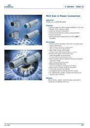
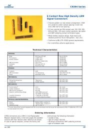
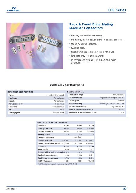
<strong>LHS</strong> <strong>Series</strong><strong>Rack</strong> & <strong>Panel</strong> <strong>Blind</strong> <strong>Mating</strong><strong>Modular</strong> <strong>Connectors</strong>• Railway flat floating connector• <strong>Modular</strong>ity mixed power, signal & coaxial contacts.• Up to 70 signal contacts.• Guiding pins.• <strong>Rack</strong>/<strong>Panel</strong> applications (norm XPF61-005)• One size only: 14 units (5.5mm)• In compliance with NF F 61-032, SNCF normapproved.Technical CharacteristicsMATERIALS AND PLATINGSFrameSide flangeInsulatorPin & socket bodySocket wiresPinFloating eyeletsSoft Steel (Zinc coated)PolycarbonatePolycarbonateBrass, Au/NiCopper alloy, Au/NiAu/NiBrass (Ni plated)ENVIRONMENTALTemperature range - 40 °C to 100 °CFire classification Exigence 2 following NF F 16-102Salt spray test96 hoursAcid withstanding Following NF F 61-032 par. 11.4.6Vibration Withstanding5 g /25 to 250 HzInsulator mechanical resistance1000 NMax torque for auto threading screws75 NcmELECTRICAL CHARACTERISTICSContact Ø Ø 1.50 Ø 2.50 Ø 3.50Creepage distance 1.85 mm 2.25 mm 4.05 mmClearance distance 1.25 mm 3.40 mm 5.40 mmWorking current 8 A 16 A 25 AInsulation resistance∃ 5.10 3 MContact resistance # 2.50 m # 1.00 m # 0.80 mDielectric withstanding voltage 1500 Vrms 2000 Vrms 3000 VrmsContact Ø Ø 1.50 Ø 2.50 Ø 3.50Voltage rating 110 V 220 V 220 VContact holding back in the module 40 N 50 N 70 NMaxi male contact mass 1.10 g 2.90 g 4.90 gMaxi female contact mass 0.70 g 1.60 g 2.70 gIF/SF* (Max value) 1.60N 9.00N 10.00N*IF/SF: Insertion and separation force according to NF F 61-032APRIL 2005263
<strong>LHS</strong> <strong>Series</strong>Ordering InformationLH S------- 14SERIESMODELSMARKED FRAME*LAYOUT(consult the facyory)Always receptacle P/N to useEx. : 102Layouts included L/RHNormalizedOther102 104 108 120 130 147101 to 1--Layouts included L/ZHNormalizedOther302 320301 to 3--PART - POLARITY01 Plug delivered without contact11** Male plug delivered with contacts02 Receptacle delivered without contact20** Female receptacle delivered with contactsTERMINATION STYLES00 Wthout contact20 Crimp termination30 Straight termination51 Wire wrap 0.656 Wire wrap 162 Post termination14PITCH NUMBER* Only normalized layouts are marked with NF N 61-032** Only for non normalized layouts264 APRIL 2005
<strong>LHS</strong> <strong>Series</strong>Plug & receptacle dimensions125 Maxi98ABCDEFGHJ2 holes ø 4.20363215Floating ± 1.2514 x 5.50 pitches = 77105Mounting side125 Maxi982 holes ø 4.20ABCDEFGHJ363215MatedA3010 10A Maxi : 20.30mini : 19.30Mounting side14 x 5.50 pitches = 77Floating ± 1.25105Dimensions are in mmAPRIL 2005265
BCDEFGHJA<strong>LHS</strong> <strong>Series</strong>Mounting example with L/RHA, L/SH, L/UH, L/VM and L/VF modulesReceptacle cabling side view5422233335432222321111111121Inviolability sealing (drop of painting)Plug cabling side viewABCDEFGHJ1211111111232222345222333345Code dateLayout identification*01 43 HYPERTAC 04 NF F 61-032ManufacturerStandard*Dimensions are in mm266 APRIL 2005
<strong>LHS</strong> <strong>Series</strong>MalesContacts - Crimp terminationsCONTACTS Ø 1.50 AWG 24-22-20-18-16-14FemalesØ 1.50Ø 3.00Ø 3.40Ø 1.80Ø 2.75Ø 3.00Ø 1.50Ø 3.00Ø 3.40Ø 1.80Ø 2.757.90 7.1525.959.10 7.1518.15Ref: 0150 761-20-OGRef: 0150 682-20-G1CONTACTS Ø 2.50*15.50 127.50 1288Ø 2.50Ø 3.50Ø 6.60Ø AØ BØ 2.50Ø AØ BRef: 0250 181-22-OGRef: 0250 201-23-OGRef: 0250 172-22-G1Ref: 0250 202-23-G1CONTACTS Ø 3.50*9Ø 7.008Ø AØ BØ 3.50Ø 6.60Ø 7.008Ø AØ B15.509.505.909.5027.5019.50Ref: 0350 111-24-OGRef: 0350 121-25-OGRef: 0350 131-26-OGRef: 0350 251-23-OGRef: 0350 112-24-G1Ref: 0350 122-25-G1Ref: 0350 132-26-G1Ref: 0350 302-23-G1Reference Ø A Ø B Ø C *AWGØ 2.500250 181-22-OG0250 172-22-G1- - 1.95 16-140250 201-23-OG0250 202-23-G1- - 1.50 22-20-18-16Ø 3.500350 111-24-OG0350 112-24-G10350 121-25-OG0350 122-25-G10350 131-26-OG0350 132-26-G10350 251-23-OG0350 302-23-G12.10 4.10 - 14-131.95 3.10 16-141.50 3.10 22-174.55 5.65 8Dimensions are in mmAPRIL 2005267
<strong>LHS</strong> <strong>Series</strong>Contacts Ø 1.50 - Wire wrap terminationMalesFemales17.50 18.809.70 18.80Ø1.50150.60Ø 1.50150.60Ref: 0151 131-51-OGRef: 0151 132-51-G14032.2Ø1.501.517.507.9 8.620 (useful)11.53.39.78.320 (useful)11.5 18.61Ref: 0151 151-56-OGRef: 0151 152-56-G1Contacts Ø 1.50 - Post termination4032.20Ø 1.5017.509.6021.5020 (useful)1.60 x 0.79Ø 1.503.309.7021.5020 (useful)1.60 x 0.798.60Ø 2.008.30Ø 2.00Ref: 0150 861-62-OG8.60Ref: 0150 862-62-G1Coaxial contacts2428.80Ø 3.6513.80Ø 1.70Ø 2.40Ø 5.23 MaxØ 3.655.90Ø 1.70Ø 2.4065.90 6.20 x 5.50 7.906.20 x 5.50Ref: 0370 031-XB-U1Ref: 0370 032-XB-U1TECHNICAL CHARACTERISTICSImpedance cable KX22A (RG316) : 50 cable RG179B/U : 75Curent rating3 AContact resistance Internal 10 milli External 0.8 milliInsulation resistance >5.10 3 M (500VDC)Temperature range -40 °C + 100 °CContact life cycle > 5000Standing wave ratio up to 1.2 (500 MHz)Dimensions are in mm268 APRIL 2005
<strong>LHS</strong> <strong>Series</strong>Modules5 x Ø 1.50L/RHL/ZH2522225.5026.59221213.54295.50429Ref: L-- 515 00 00 RHA BentRef: L -- 515 00 00 ZHACoudée 903 x Ø 2.50 2 x Ø 3.50L/SHL/UH2222136.58.25321111213.51213.5297.6 7.65.6 5.6 5.6299.5Ref: L-- 325 00 00 SH9Ref: L-- 235 00 00 UHCoudée 90Dimensions are in mmAPRIL 2005269
<strong>LHS</strong> <strong>Series</strong>ModulesModules equipped with contacts for KX15 coax cableL/VML/VFØ 3.65293.50 22Ø 108.8011113212Ø 108.8011119271222292229Ref: L-- 1CX 11 40 VM BentRef: L -- 1CX 20 40 VFCoudée 90TECHNICAL CHARACTERISTICSSocket wiresCopper alloy, Au/NiImpedence 50Dielectric withstanding voltage internal 1000 Vrms external 4800 VrmsCurent rating2 ATemperature range -40 °C + 100 °CContact resistance Internal 10 milli External 1 milliModule pitches number 4 as 22 mmInsulation resistance > 5.10 4 M (500 VDC)Recommended cableKX15Dimensions are in mm270 APRIL 2005
A<strong>LHS</strong> <strong>Series</strong><strong>Panel</strong> cut outReceptacle panel cut out1050.1B930.1B350.1A0.1A152 holes Ø 4.20 Guiding pin passB980.1BPlug panel cut out0.1A1050.1B930.1B350.1A15A2 holes Ø 4.20BDimensions are in mmAPRIL 2005271
<strong>LHS</strong> <strong>Series</strong>Crimping toolsContact part number Crimp tool Gauje AWG Wire cross section Positioner Tool turret Selector position24 0.22 222 0.34 3ASTRO TOOLASTRO TOOL 20 0.604TGV 101 18 0.93 5TGV 202 red16 1.34614 1.91 724 0.22 222 0.343DANIELS0150 682-20-G1 DANIELS 20 0.60 40150 761-20-OG FT8 18 0.93 5SH 463 red16 1.34614 1.91 722 0.3420 0.60ASTRO TOOLSS.015000000218 0.93MS 3191/1HYPERTACWithout16 1.3414 1.9116 1.34 615 1.50 ASTRO TOOL 6ASTRO TOOL15 1.82 7TGV 10114 1.91 TGV 202 blue 70250 181-22-OG14 2.00 70250 172-22-G116 1.34 615 1.5 DANIELS 6DANIELS15 1.82 7FT814 1.91 SH 463 blue 714 2.00 70250 201-23-OG0250 202-23-G10350 111-24-OG0350 112-24-G10350 121-25-OG0350 122-25-G10350 131-26-OG0350 132-26-G10350 251-23-OG0350 302-23-G1ASTRO TOOLTGV 101DANIELSFT8DANIELSM317ASTRO TOOLTGV 51522 0.34 520 0.60 ASTRO TOOL 618 0.93 618 1.00 TGV 202 blue 616 1.34 622 0.34 520 0.60 DANIELS 618 0.93 618 1.00 SH 463 blue 616 1.34 614 1.91 3DANIELS14 2.003TP 80513 2.50414 1.913ASTRO TOOL14 2.003Without TGV 50313 2.50 416 1.34 2DANIELS 15 1.50 DANIELS 2M317 14 1.91 TP 805 314 2.00 316 1.34 2ASTRO TOOL 15 1.50 ASTRO TOOL 2TGV 515 14 1.91 Without TGV 503 314 2.00 322 0.38 1DANIELS 20 0.60 DANIELS 1M317 18 0.93 TP 805 218 1.00 222 0.38 1ASTRO TOOL 20 0.60 ASTRO TOOL 1TGV 515 18 0.93 Without TGV 503 218 1.00 2ASTRO TOOLTGV 515DANIELSM300 BT8 8.98 M22520/1,05 48 8.98 M22520/1,05 4272 APRIL 2005
<strong>LHS</strong> <strong>Series</strong>Insertion and extraction toolsMALESFEMALESContact Ø Part number Part number Insertion tool Extracting toolS_059 (1)1.50 0150 761-20-OG 0150 682-20-G1SM-0150000002 (2) S__ 072SM-0150000003 (3)2.503.500250 181-22-OG 0250 172-22-G10250 201-23-OG 0250 202-23-G10350 111-24-OG 0350 112-24-G10350 121-25-OG 0350 122-25-G10350 131-26-OG 0350 132-26-G10350 251-23-OG 0350 302-23-G1SM-0150000000 (4)SE-0250000001 S__ 078SE-0350000001 S__ 083 (5)(1) straight tool(2) unwedge tool(3) bent tool(4) 3 tool kit(5) tool for Ø 1.50, 2.50 et 3.50 contactsAPRIL 2005273