Download - R+L HYDRAULICS
Download - R+L HYDRAULICS
Download - R+L HYDRAULICS
- No tags were found...

Create successful ePaper yourself
Turn your PDF publications into a flip-book with our unique Google optimized e-Paper software.
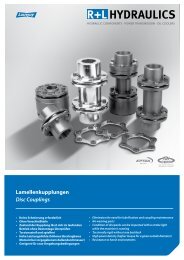
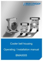
Bell housingOperating / Installation manualBMA0003
Raja-Lovejoy GmbH Bell housing Number: BMA0003Friedrichstr. 6 operating / Page: 1 of 11D-58791 Werdohl installation manual Version: 1ENGTable of contents:1.0 General information: ........................................................................ 31.1 Safety and information symbols: ................................................................ 31.2 General hazard warnings:............................................................................ 32.0 Intended use: .................................................................................... 43.0 Dimensions: ...................................................................................... 4Figure 1: Diagram of fixed version & integrated damped version ................. 4Figure 2: Diagram of fixed version & multi‐part damped version .................. 4Table 1: Motor flange dimensions ø160 ‐ ø200 ‐ part 1 ................................. 5Table 2: Motor flange dimensions ø400 ‐ ø800 ‐ part 2 ................................. 5Figure 3: Diagrams of bell housing for gear pumps ....................................... 6Table 3: Motor flange dimensions ø160mm .................................................. 6Table 4: Motor flange dimensions ø200mm .................................................. 7Table 5: Motor flange dimensions ø250mm .................................................. 7Table 6: Motor flange dimensions ø300mm .................................................. 8Table 7: Motor flange dimensions ø350mm .................................................. 8Table 8: Motor flange dimensions ø400mm .................................................. 84.0 Assembly .......................................................................................... 9Figure 4: Grille ................................................................................................ 9Figure 5: Plug .................................................................................................. 9Copyright reserved Signed: 27.09.2010 MBOZ Replacement for:as per ISO 16016 Checked: 01.04.2011 JZIS Replaced by:
Raja-Lovejoy GmbH Bell housing Number: BMA0003Friedrichstr. 6 operating / Page: 2 of 11D-58791 Werdohl installation manual Version: 1ENG4.1 Fitting the bell housing to the electric motor ............................................10Figure 4: Exploded diagram: Motor / Bell housing / Pump ..........................10Table 9: Tightening torques .........................................................................105.0 Additional information: .................................................................. 11Copyright reserved Signed: 27.09.2010 MBOZ Replacement for:as per ISO 16016 Checked: 01.04.2011 JZIS Replaced by:
Raja-Lovejoy GmbH Bell housing Number: BMA0003Friedrichstr. 6 operating / Page: 3 of 11D-58791 Werdohl installation manual Version: 1ENGThe bell housing connects the electric motor and the hydraulic pump. Bell housings areproduced in aluminium, cast iron, and steel.1.0 General information:Carefully read through this installation manual before installing the bell housing. Payparticular attention to the safety instructions!The installation manual is part of your product. Store it carefully and in the vicinity of the bellhousing.The copyright for this installation manual shall remain with Raja-Lovejoy GmbH.1.1 Safety and information symbols:DangerRisk of injury to personnelCautionDamage could occur to the machineNote Note regarding important information1.2 General hazard warnings:During installation and removal of the bell housing, make sure that the entiredrive train is secured to prevent accidental activation, and that the system isdepressurised. Rotating parts can cause serious injury. For this reason, thefollowing safety instructions should be read and followed without exception.• All work on the bell housing should be performed from the perspective of->“Safety First”• Secure the drive unit to prevent unintentional activation, e.g. by attaching informationsigns to the switch-on points or removing the fuse at the power supply.• Do not reach into the working area of the machine while it is still in operation.• Protect the rotating parts to prevent accidental touching. Attach the relevant protectivedevices and covers.Copyright reserved Signed: 27.09.2010 MBOZ Replacement for:as per ISO 16016 Checked: 01.04.2011 JZIS Replaced by:
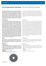
Raja-Lovejoy GmbH Bell housing Number: BMA0003Friedrichstr. 6 operating / Page: 4 of 11D-58791 Werdohl installation manual Version: 1ENG2.0 Intended use:You may only install and maintain the bell housing if you:• have carefully read and understood the installation manual• are authorised and trained to do soThe bell housing may only be used in accordance with the technical specifications.Unauthorised structural changes to the bell housing are prohibited. We will not accept anyliability for damage occurring as a result of this. In the interest further development, wereserve the right to make technical changes. The bell housings described here correspondwith the latest technical standards at the time of publication of this installation manual. Thebell housing is usually delivered ready for installation.3.0 Dimensions:Figure 1: Diagram of fixed version & integrated damped versionFigure 2: Diagram of fixed version & multi-part damped versionCopyright reserved Signed: 27.09.2010 MBOZ Replacement for:as per ISO 16016 Checked: 01.04.2011 JZIS Replaced by:
Raja-Lovejoy GmbH Bell housing Number: BMA0003Friedrichstr. 6 operating / Page: 5 of 11D-58791 Werdohl installation manual Version: 1ENGTable 1: Motor flange dimensions ø160 - ø200 - part 1Table 2: Motor flange dimensions ø400 - ø800 - part 2Copyright reserved Signed: 27.09.2010 MBOZ Replacement for:as per ISO 16016 Checked: 01.04.2011 JZIS Replaced by:
Raja-Lovejoy GmbH Bell housing Number: BMA0003Friedrichstr. 6 operating / Page: 6 of 11D-58791 Werdohl installation manual Version: 1ENGFigure 3: Diagrams of bell housing for gear pumpsTable 3: Motor flange dimensions ø160mmCopyright reserved Signed: 27.09.2010 MBOZ Replacement for:as per ISO 16016 Checked: 01.04.2011 JZIS Replaced by:
Raja-Lovejoy GmbH Bell housing Number: BMA0003Friedrichstr. 6 operating / Page: 7 of 11D-58791 Werdohl installation manual Version: 1ENGTable 4: Motor flange dimensions ø200mmTable 5: Motor flange dimensions ø250mmCopyright reserved Signed: 27.09.2010 MBOZ Replacement for:as per ISO 16016 Checked: 01.04.2011 JZIS Replaced by:
Raja-Lovejoy GmbH Bell housing Number: BMA0003Friedrichstr. 6 operating / Page: 8 of 11D-58791 Werdohl installation manual Version: 1ENGTable 6: Motor flange dimensions ø300mmTable 7: Motor flange dimensions ø350mmTable 8: Motor flange dimensions ø400mmCopyright reserved Signed: 27.09.2010 MBOZ Replacement for:as per ISO 16016 Checked: 01.04.2011 JZIS Replaced by:
Raja-Lovejoy GmbH Bell housing Number: BMA0003Friedrichstr. 6 operating / Page: 9 of 11D-58791 Werdohl installation manual Version: 1ENG4.0 AssemblyThe screws should normally be secured with Loctite, Omnifit 230M or acomparable thread adhesive.To achieve the full loading capacity of the bell housings, all fasteningholes must be screwed to the electric motor.Figure 4: GrilleIf the bell housing in question has leakage or installation holes they should besealed, according to instructions, to make it impossible to touch the rotatingcoupling. We offer grilles and plugs for this purpose.Figure 5: PlugCopyright reserved Signed: 27.09.2010 MBOZ Replacement for:as per ISO 16016 Checked: 01.04.2011 JZIS Replaced by:
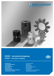
Raja-Lovejoy GmbH Bell housing Number: BMA00031Friedrichstr. 6 operating / Page: 0 of 11D-58791 Werdohl installation manual Version: 1ENG4.1 Fitting the bell housing to the electric motor• The bell housing is slid onto the centring device of the electric motor and the hydraulicpump, and screwed into place. Only use the existing threaded holes in the bell housing toscrew it together with the electric motor.• Insert the cheese head screws (per DIN 912) into the through-holes of the electric motorflange and screw them into the threaded holes in the bell housing. Preferably, a screwlength should be selected which enables the entire thread depth of the threaded holes to beused in the bell housing.• Please see Table 9 for the screw tightening torques for the electric motor.• The screw tightening torques for the hydraulic pump can be found in the technicaldocumentation of the hydraulic pump manufacturer.Figure 4: Exploded diagram: Motor / Bell housing / PumpTable 9: Tightening torquesCopyright reserved Signed: 27.09.2010 MBOZ Replacement for:as per ISO 16016 Checked: 01.04.2011 JZIS Replaced by:
Raja-Lovejoy GmbH Bell housing Number: BMA00031Friedrichstr. 6 operating / Page: 1 of 11D-58791 Werdohl installation manual Version: 1ENG5.0 Additional information:• The bell housings can be used either horizontally or vertically.The customer is responsible for ensuring that there is a proper seal betweenthe bell housing and the hydraulic pump.Seals for this purpose can be ordered from us.Copyright reserved Signed: 27.09.2010 MBOZ Replacement for:as per ISO 16016 Checked: 01.04.2011 JZIS Replaced by: