Conversion to 16-inch tyres and 71/2 J _16 H 2 ET 40 ... - w-124.info
Conversion to 16-inch tyres and 71/2 J _16 H 2 ET 40 ... - w-124.info
Conversion to 16-inch tyres and 71/2 J _16 H 2 ET 40 ... - w-124.info
- No tags were found...

You also want an ePaper? Increase the reach of your titles
YUMPU automatically turns print PDFs into web optimized ePapers that Google loves.
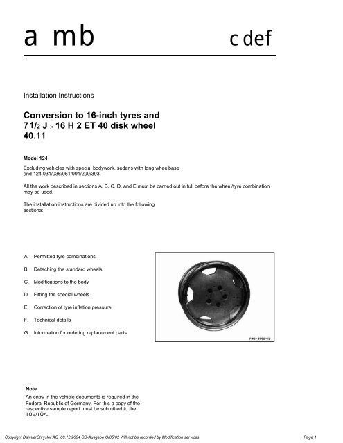
ambcdefInstallation Instructions<strong>Conversion</strong> <strong>to</strong> <strong>16</strong>-<strong>inch</strong> <strong>tyres</strong> <strong>and</strong>7 1/2 J _ <strong>16</strong> H 2 <strong>ET</strong> <strong>40</strong> disk wheel<strong>40</strong>.11Model 124Excluding vehicles with special bodywork, sedans with long wheelbase<strong>and</strong> 124.031/036/051/091/290/393.All the work described in sections A, B, C, D, <strong>and</strong> E must be carried out in full before the wheel/tyre combinationmay be used.The installation instructions are divided up in<strong>to</strong> the followingsections:A. Permitted tyre combinationsB. Detaching the st<strong>and</strong>ard wheelsC. Modifications <strong>to</strong> the bodyD. Fitting the special wheelsE. Correction of tyre inflation pressureF. Technical detailsG. Information for ordering replacement partsNoteAn entry in the vehicle documents is required in theFederal Republic of Germany. For this a copy of therespective sample report must be submitted <strong>to</strong> theTÜV/TÜA.Copyright DaimlerChrysler AG 08.12.2004 CD-Ausgabe G/05/02 Will not be recorded by Modification services Page 1
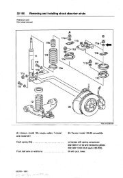
A. Permitted tyre combinationsModel Front axle Rear axle Comments124.02/030/04/050124.12/13124.226/230124.330/333124.08/090124.18/19205/55 R <strong>16</strong> 205/55 R <strong>16</strong> All Sedans, Coupés, (including4MATIC, excluding 24 V)205/55 R <strong>16</strong> 225/50 R <strong>16</strong> All T-Sedans (excluding 4MATIC<strong>and</strong> 24 V)B. Detaching the st<strong>and</strong>ard wheels1 Remove wheel covers on steel disk wheels.2 Slacken wheel bolts.3 Raise vehicle.4 Unscrew wheel bolts.NoteWhen unscrewing the final wheel bolt be sure thatthe wheel does not suddenly tilt off the hub.5 Remove wheel.MFive of the st<strong>and</strong>ard wheel bolts removed must beretained for the spare wheel.C. Modifications <strong>to</strong> the body1 Adjusting the front fenderCopyright DaimlerChrysler AG 08.12.2004 CD-Ausgabe G/05/02 Will not be recorded by Modification services Page 2
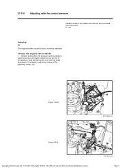
1.1 Detach side panel on the front fender from thefixing elements, pull <strong>to</strong> the rear <strong>and</strong> remove.1.2 Unscrew bolts (A <strong>and</strong> B) on fender.1.3 Slacken bolt (A) on side of bumper.Copyright DaimlerChrysler AG 08.12.2004 CD-Ausgabe G/05/02 Will not be recorded by Modification services Page 3
1.4 Press the side part of the bumper downwards<strong>and</strong> unscrew the bolts for fender fixing (A <strong>and</strong> B).Clamp a spacer between fender <strong>and</strong> body on theleft <strong>and</strong> the right. The bore holes must align <strong>to</strong>permit troublefree fixing.1.5 Place one spacer on the left <strong>and</strong> right betweenthe fender <strong>and</strong> body in the side area of the bumper.1.6 Tighten all bolts slightly in accordance withlayout. Tighten bolts after a visual inspection.2 Reworking the body at the front fendersCopyright DaimlerChrysler AG 08.12.2004 CD-Ausgabe G/05/02 Will not be recorded by Modification services Page 4
2.1 Flattening down front fender flange:When converting <strong>to</strong> wider wheels <strong>and</strong> <strong>tyres</strong> the insideedges of the front fender must be flattened down <strong>to</strong> anangle of 110° over the complete wheel cu<strong>to</strong>ut.2.2 If excessive PVC underbody protection hasbeen applied, grind off excess before folding back thefender flange.2.3 Using a hot air gun carefully heat up outer edgesof fender <strong>to</strong> a maximum of 70° - 80°C.NoteDo not overheat paint whilst applying heat(max. 80°C).2.4 In the marked area (A), the fender flange isflattened down up <strong>to</strong> the inside of the fender in severalstages. A plastic hammer must be used <strong>to</strong> avoiddamaging the paint.2.5 Allow front fender flare <strong>to</strong> curve smoothly back<strong>to</strong>wards original, unflared line within the marked area(B).NoteRectify any damage <strong>to</strong> paint or underbody protection.2.6 Grind off side panel <strong>to</strong> match the reworkedfender con<strong>to</strong>ur <strong>and</strong> assemble.3 Folding back the edge of rear fenderCopyright DaimlerChrysler AG 08.12.2004 CD-Ausgabe G/05/02 Will not be recorded by Modification services Page 5
3.1 If excessive PVC underbody protection hasbeen applied, grind off excess before folding backthe edge of the fender.3.2 Using a hot air gun carefully heat up outeredges of fender <strong>to</strong> a maximum of 70° - 80°C.NoteDo not overheat paint whilst applying heat(max. 80°C).3.3 In the marked area (A), the edge of the fenderis flattened down as far as the inside of the fender inseveral stages.A plastic hammer must be used <strong>to</strong> avoid damagingthe paint.NoteRectify any damage <strong>to</strong> paint or underbody protection.3.4 Treat wheel arch again with underbodyprotection. Spray the folded back fender edges withbody cavity preserver.D. Fitting the special wheelsCopyright DaimlerChrysler AG 08.12.2004 CD-Ausgabe G/05/02 Will not be recorded by Modification services Page 6
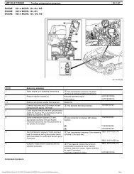
1 Screw in centering bolts (<strong>to</strong>ol kit) in uppertapped hole of the wheel hub.2 Put on AMG light alloy wheel <strong>and</strong> press on<strong>to</strong>wheel hub.3 Screw in wheel bolts <strong>and</strong> tighten positively. Thewheel bolts must be dry <strong>and</strong> free from grease.Ensure that the wheels are not tensioned bytightening the wheel bolts on one side. (Tightenwheel bolts diagonally in several stages).MOnly M12 x 1.5 x <strong>40</strong> mm spherical collar boltssupplied with the rims are <strong>to</strong> be used for the wheelfixing.4 Unscrew centering bolt <strong>and</strong> replace by a wheelbolt.5 Lower vehicle.6 Evenly tighten wheel bolts diagonally <strong>to</strong> atightening <strong>to</strong>rque of 110 Nm.MAMG light alloy wheel bolts must be retightened after100-500 km. (Tightening <strong>to</strong>rque 110 Nm).NoteFitting snow chains is not permitted.E. Correction of tyre inflation pressureaaThe minimum tyre inflation pressures requiredcan be obtained from the tyre inflation pressuretable (appendix).The front axle or rear axle tyre inflationpressures determined are <strong>to</strong> be noted on theAMG sticker using a waterproof felt tip pen.Attach sticker <strong>to</strong> a suitable point on the loadingedge of luggage compartment.Copyright DaimlerChrysler AG 08.12.2004 CD-Ausgabe G/05/02 Will not be recorded by Modification services Page 7
F. Technical detailsManufacturer:AMG/RUOTE OZModel: C 7 <strong>40</strong> 0119Wheel size: 7 1/2 J _ <strong>16</strong> H 2Offset:Pitch circle:Permitted wheel load:Centering:Type:<strong>40</strong> mmd=112 mm, 5 hole615 kg at rdyn=307 mmCentral centering d=66.5+0.1One-piece light alloy wheel with double humpMarking: Outer side of wheel: AMG GermanyC 7 <strong>40</strong> 01197 1/2 J _ <strong>16</strong> H 2 <strong>ET</strong> <strong>40</strong>Inner side of wheel:RUOTE OZ (foundry symbol)<strong>and</strong> date of manufactureValves: Metal screw-on valves in accordance with DIN 7779with long nutFixing:Tightening <strong>to</strong>rque:Balance weights:Only with M12 x 1.5 x <strong>40</strong> mm spherical collar bolts supplied by the wheelmanufacturer110 NmOnly adhesive weights are permittedG. Information for ordering replacement partsReplacement partsDesignationPart no.Copyright DaimlerChrysler AG 08.12.2004 CD-Ausgabe G/05/02 Will not be recorded by Modification services Page 8
Light alloy disk wheel 7 1/2 J _ <strong>16</strong> H 2 <strong>ET</strong> <strong>40</strong> B6 602 00 57Wheel trim B6 602 00 96Spherical collar bolt L=<strong>40</strong> mm H WA201 <strong>40</strong>1 02 70Valve H WA201 <strong>40</strong>0 01 13Tyre pressure sticker H WA201 584 00 39Fender extension kit B6 602 00 72NoteA set of wheel locking bolts(Part no. B6 602 02 01) can be supplied uponrequest.<strong>Conversion</strong> <strong>to</strong> AMG 7 1/2 J _ <strong>16</strong> H 2 <strong>ET</strong> <strong>40</strong> disk wheelRefer <strong>to</strong> page 2 for tyre dimensions.Passenger carModel 124 sedan/coupé/T-modelThe appendix is divided up in<strong>to</strong> the following sections:A. Assignment of tyre make/modelB. Specified minimum tyre inflation pressuresA. Permitted makes of tyreVehicle model 124MakeDescriptionSedan Coupé T-modelBridges<strong>to</strong>ne RE <strong>71</strong> X X XMichelin MXX X X XDunlop SP Sport D <strong>40</strong> X X XPirelli P 700 Z X X XPirelli P 700/P 7 X X not permittedGoodyear Eagle VR/NCT X X not permittedB. Specified minimum tyre inflation pressures (bar)Copyright DaimlerChrysler AG 08.12.2004 CD-Ausgabe G/05/02 Will not be recorded by Modification services Page 9
Refer <strong>to</strong> page 2 for tyre dimensions.Vehicle model: 124 sedan/coupé/T-modelPermitted maximumspeedVmax (km/h)1)Front axleRear axleLevel control systemPerm. rear axle load (kg)1)Permitted front axleload (kg)1)Steel suspensionPerm. rear axle load (kg)1)205/55 225/50 205/55up <strong>to</strong> 1015 up <strong>to</strong> 1055 up <strong>to</strong> 1025 up <strong>to</strong> 1230 up <strong>to</strong> 1025210 2.8 2.7 3.1 3.0 2.9 2.8220 2.9 2.8 3.2 3.1 3.0 2.9230 3.0 2.9 3.3 3.2 3.1 3.02<strong>40</strong> 3.1 3.0 3.4 3.3 3.2 3.1250 3.2 3.1 3.5 3.5 3.3 3.2225/50up <strong>to</strong> 1230Max. wheel camberangle (degrees) - 1°30' - 4° - 2°30'1) Values for maximum speed <strong>and</strong> permitted front axle or rear axle loads can be obtained from the vehicle documents.Comments:aaaaaTyre inflation details only apply for vehicles with a maximum speed of up <strong>to</strong> 250 km/h.The tyre inflation pressure can be reduced by p = 0.1 (bar) per 100 kg reduction in axle load.Remember that tyre inflation pressure details only apply for cold <strong>tyres</strong>!On warm <strong>tyres</strong> values of up <strong>to</strong> 0.5 bar higher are permissible. Do not reduce pressure of warm <strong>tyres</strong>!Tyre inflation pressure may only be corrected when <strong>tyres</strong> are cold!Tyre inflation pressure details relate <strong>to</strong> the use of permitted maximum speed <strong>and</strong> permitted axle load.Copyright DaimlerChrysler AG 08.12.2004 CD-Ausgabe G/05/02 Will not be recorded by Modification services Page 10
![[Buying Guide] - W124 Performance](https://img.yumpu.com/51307820/1/190x245/buying-guide-w124-performance.jpg?quality=85)