Technical data1.0 MB - Viessmann
Technical data1.0 MB - Viessmann
Technical data1.0 MB - Viessmann

Create successful ePaper yourself
Turn your PDF publications into a flip-book with our unique Google optimized e-Paper software.
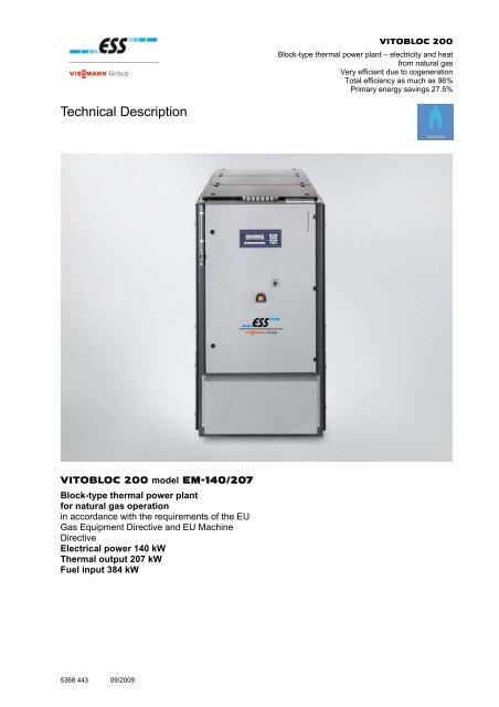
VITOBLOC 200Block-type thermal power plant – electricity and heatfrom natural gasVery efficient due to cogenerationTotal efficiency as much as 96%Primary energy savings 27.5%<strong>Technical</strong> DescriptionVITOBLOC 200 model EM-140/207Block-type thermal power plantfor natural gas operationin accordance with the requirements of the EUGas Equipment Directive and EU MachineDirectiveElectrical power 140 kWThermal output 207 kWFuel input 384 kW5368 443 09/2009
Legal NoticeThis equipment satisfies the basicrequirements of the appropriate standardsand directives. Its conformity has beendemonstrated. These documents and theoriginal conformity declaration are stored onthe premises of the manufacturer.Important general instructions for applicationOnly use this technical equipment as intended andcomplying with the assembly instructions, operatinginstructions and service instructions. Only authorisedprofessionals should service and repair it.Only operate this technical equipment in the combinationsand with the accessories and replacement parts referred toin the assembly instructions, operating instructions andservice instructions. Only use other combinations,accessories and wear parts if they are explicitly intended forthe specific application and do not impair the performancefeatures or safety requirements.Subject to change without notice.This is a component of the original operating instructions.Figures, steps in certain functions and technical data maydiffer slightly due to constant advancements.Updating the documentationPlease get in contact with us if you have suggestions forimprovement or have discovered any irregularities.5368 443 09/20092 ESS Energie Systeme & Service GmbH VITOBLOC 200 EM-140/207
Table of Contents1 General Statements .......................................................................... 41.1 Continuous output in parallel operation ....................................................................... 51.2 Stand-by operation .......................................................................................................... 51.3 Emissions of pollution .................................................................................................... 51.4 Energy balance sheet ..................................................................................................... 62 Product description .......................................................................... 72.1 Gas spark-ignition engine with accessories ................................................................ 72.2 Coupling ......................................................................................................................... 102.3 The three-phase synchronous alternator ................................................................... 102.4 Basic frame .................................................................................................................... 102.5 Piping ............................................................................................................................. 112.6 Heat transfer system ..................................................................................................... 112.7 Exhaust gas purification system and exhaust gas front silencer ........................... 122.8 Lubricating oil supply system ...................................................................................... 122.9 Sound insulation hood and exhaust ventilator cowl ................................................ 122.10 Series-production accessories .................................................................................... 132.11 Monitoring equipment ................................................................................................... 142.12 Switching cabinet .......................................................................................................... 152.13 Check-list for stand-by operation ................................................................................ 173 Service and maintenance ............................................................... 183.1 Service and maintenance list ....................................................................................... 194 <strong>Technical</strong> Data ................................................................................. 214.1 Operating parameters for the cogeneration module ................................................. 214.2 <strong>Technical</strong> data of a complete cogeneration module .................................................. 234.3 Dimensions, Weights and Colours .......................................................................... 254.4 Installation ..................................................................................................................... 264.5 Start-stop ratio ............................................................................................................... 264.6 Ecotax in Germany ........................................................................................................ 265 Important information on planning and operation ....................... 285.1 Malfunctions .................................................................................................................. 286 Index ................................................................................................. 297 Conformity declaration ................................................................... 308 Brief instructions ............................................................................ 315368 443 09/2009VITOBLOC 200 EM-140/207 ESS Energie Systeme & Service GmbH 3
General Statements1.1 Continuous output in paralleloperationRefer to page 21, Table 6 for outputs and efficiency.The outputs and efficiency satisfy the requirements ofthe standards ISO 3046/1 at 25° C air temperature,100 kPa air pressure (up to 100 m installation heightabove sea level), 30% relative humidity and methanenumber 80 and reactive factor cos phi = 1. Thetolerance for all efficiency, heat output and energyapplications is 5%.All other data for the cogeneration module applies toparallel operation. You are receiving the data for thepartial load range for the purpose of information(although there is no guarantee corresponding to ISOand DIN).Only use natural gas fuel that is acceptable inaccordance with DVGW Directive G260, 2nd gasfamily, group L. You can get all of the data needed forother gas quantities and installation conditions at yourrequest.Current characteristic numberThis cogeneration module is a series product with theproduct number (CE-0433BT0002) in accordance withthe Gas Equipment Directive without heat dissipationequipment.The current characteristic number is defined as thequotient of the electrical output divided by the heatoutput as per the AGFW FW308 worksheet. Thefigure in Table 6 (page 21) is in the defined rangebetween 0.5 and 0.9 for internal combustion enginecogeneration systems.Primary energy factor ENEV 2007The primary energy factor (abbreviated »fp«) givesthe ratio of primary energy used to final energyreleased and this factor not only includes energytransformation, but also transport. In other words,that means that the lower the primary energy factor is,the better it is for ascertaining the annual primaryenergy needs. The fewer resources utilised by theform of energy used and its transformation, the lowerthe primary energy factor.1.2 Stand-by operationThe cogeneration modules can also be used asstand-by aggregates if the electricity grid fails instand-by operation if the customer’s main low-voltagedistribution is appropriately designed.If there is a power failure when the block-type thermalpower plant is shut down, the first cogenerationmodule can be started and automatically enabled as astand-by rail within 15 seconds.Output will be reduced by 10% to have sufficientregular reserves in stand-by operation. Theconsumers entitled to stand-by power should bebrought into load in stages (for instance, 40% – 40% –10%).The hot water return temperature may not be inexcess of 65° C either in stand-by operation orparallel operation.The stand-by operation function does not apply inconnection with operating an absorption refrigeratingmachine.1.3 Emissions of pollutionThe following emission values after the exhaust gaspurification system refer to dry exhaust gas at 5%residual oxygen content.Emission valuesNO x content* measured as NO 2CO content*Formaldehyde CH 2 O< 125 mg/Nm³< 150 mg/Nm³< 129 mg/kWh< 60 mg/Nm³Emission values in accordance with ½ <strong>Technical</strong> Instruction on AirTab. 2Emission values after exhaust gas purificationPrimary energy savings in accordance with theEU Cogeneration DirectiveThe level of primary energy saved is the percentagesavings of fuels with combined power and heatgeneration within a cogeneration process in relation tothe fuel heat consumed in reference systems of noncombinedpower and heat generation.The calculation formula is defined in Appendix III ofthe EU Directive 2004/8/EC on promotingcogeneration geared towards available heat needs.5368 443 09/2009VITOBLOC 200 EM-140/207 ESS Energie Systeme & Service GmbH 5
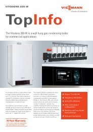
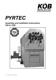
General Statements1.4 Energy balance sheetThe energy balance sheet shows you a graph of theenergy flow of the cogeneration module.The energy balance sheet illustrates thetransformation of primary energy (natural gas, 100%)into electrical and thermal collectable energy. Thelosses occurring with this transformation are alsoshown.The electrical collectable energy comes from thecombustion process in the spark-ignition engine and.is transformed into current through this rotatingmovement via a synchronous alternator.The thermal collectable energy comes from thecombustion process in the spark-ignition engine. It isdistributed to the exhaust gas heat, the collector pipe,the engine block and engine lubricating oil and it isused for heating water.The entire efficiency of a cogeneration module resultsfrom the total of the electrical and thermal collectableenergy.Fig. 1The energy balance sheet of the cogeneration module5368 443 09/20096 ESS Energie Systeme & Service GmbH VITOBLOC 200 EM-140/207
Product description2 Product descriptionThe cogeneration module consists of a wide variety ofsubassemblies and components that this chapter willexplain to you. The subassemblies and componentsare part of the scope of delivery of the cogenerationmodule.2.1 Gas spark-ignition engine withaccessories2.1.1 Gas spark-ignition engineThis gas spark-ignition engine is operated as aninternal combustion engine (aspirating engine) withoutturbocharging and at an air ratio of lambda = 1.A compressed oil jet cools the piston heads. Theexhaust gases are drained through a water-cooledexhaust gas collector pipe.ComponentsThe crankcase is cast in one piece together with thecylinder block. The cylinder support with6 cylinders arranged in line forms the close of thecrankcase. The cylinder liners are wet-running,replaceable and made of cast iron. The gearbox isarranged on the flywheel side of the crankcase. Itincludes the crankshaft seal and drive gears for thecamshaft and oil pump. The crankshaft made ofchromium-molybdenum steel is forged in the forgingdie and nitride hardened. It is lodged at the end andbetween the cylinders. The crank pins are intendedfor lodging one connecting rod each.The bearing shells are made of lead/bronze with alead/indium covering and they have a steel back. Theconnecting rods are also forged of chromiummolybdenumsteel in the forging die and they aremade slanted.The pistons are made of a low-expansion aluminiumalloy. The form of the piston crown creates an opencombustion chamber. Three grooves are embeddedinto the piston crown for the piston rings. Thecamshaft is made of a cast iron/chromium alloy withhardened cams and lodged at the ends and betweenthe pistons.It is arranged lying low in the crankcase. The cylinderheads made of cast iron for each cylinder arefastened onto the crankcase. They have coolingducts, holes drilled for holding the spark plugs andone intake and exhaust valve per cylinder. Thevalves mounted to be suspended have replaceablevalve bushings.2.1.2 Engine lubricating oil systemThe engine is lubricated with a pressure circulatinglubrication system.The oil is pumped via gear-driven oil pump from theoil sump through the oil cooler that is designed as anoil/water ribbed tube cooler. The lubricating oil ispurified through an oil filter cartridge with a paperinsert in the main flow. From there, the filtered oil isdistributed over various oil channels.The oil lubricates the crankshaft bearings, theconnecting rod bearings, the piston pins, the camshaftbearings and the rocking arms. The gears arelubricated in the gearbox with splash oil within thecrankcase. The crank space ventilation is connectedto the combustion air suction via oil screen.ComponentsThe engine lubricating oil system consists of the oilsump, an oil pump, and oil filter with a paper insertand various oil channels.Special characteristicsThe crank space ventilation is connected to thecombustion air suction via an oil screen.5368 443 09/2009VITOBLOC 200 EM-140/207 ESS Energie Systeme & Service GmbH 7
Product description2.1.3 Engine cooling systemThe engine is cooled with a closed water circuit.The pump presses the cooling water into the crankcasethrough the oil cooler. The cylinder pins and cylinderheads are cooled with the built-in cooling water ductswithin the crankcase. The cooling water leaves theengine again after flowing through the water-cooledexhaust gas collector pipe.ComponentsThe engine cooling system consists of an electricallydriven pump, a safety excess pressure valve and amembrane expansion vessel.Special characteristicsSuitable action should be taken to protect the enginefrom excessively low cooling water temperatures due tothe heating water return tempered at too low a level oran excessively large heating water volume flow such asreturn rise or hydraulic switching. Consequentialdamage due to continuous operation outsideacceptable operating parameters is excluded from thewarranty.2.1.4 Engine starterThe engine starter supports the starting process of thegas spark-ignition engine.The engage relay is used both for pushing the pinionwith tracking into the engine’s gear rim and closing thecontact bridge for switching on the main starter current.Single-track operation of the single-track gear is formedso that the pushing motions of the engage relay and therotating motions of the electrical starter engine canoverlap in any conceivable tracking situation. The freewheel(overrunning clutch) ensures that the pinion isentrained if the rotor shaft is driving, although theconnection between the pinion and the rotor shaft isloosened when the pinion runs more quickly(overrunning).ComponentsThe engine starter is equipped with an engage relayand a single-track relay. The sliding-gear startingengine has a voltage supply of 24 V with a powerconsumption of 6.5 kW.2.1.5 The battery starter systemThe two batteries supply the electrical energy forstarting the engine to the engine starter and theignition system (24 V). The batteries also supply theelectrical energy for the monitoring and regulatingequipment (24 V).ComponentsThe two batteries (lead batteries, 170 Ah, 2 x 12 V) aremaintenance-free and filled with liquid electrolyte.Special characteristicsThese batteries are supplied precharged dry and filledwhen starting the cogeneration module.2.1.6 Combustion air filterThe combustion air filter filters the combustion air fed tothe gas spark-ignition engine.ComponentsThe combustion air filter is a two-stage dry air filtermade of fully recyclable plastic with replaceable paperfilter cartridges. It is built into the feed air line (on thefilter output). The low pressure may not be any morethan 30 mbar in front of the gas mixer.Special characteristicsThe air filter has to be serviced according to thespecifications in the maintenance plan and applying thespecific conditions at the place of installation.5368 443 09/20098 ESS Energie Systeme & Service GmbH VITOBLOC 200 EM-140/207
Product description2.1.7 The gas lane and gas-air mixer5368 443 09/2009The cogeneration module is supplied with gas througha modular safety gas lane (components approved inaccordance with DVGW).The gas-air mixer with the flanged butterfly valveworks according to the Venturi principle and mixes thegas with the combustion air.Components and functionsThe gas lane is in the cogeneration module inaccordance with DIN 6280 Part 14 and consists of:Precision gas filter (included in the delivery)The precision gas filter protects downstreamequipment from soiling. The matted fleece filter matmade of polypropylene offers a high level offlowthrough output, a high degree of purification andlong service lives. The precision gas filter is mountedoutside of the module.Elastic stainless steel hose line (included in thedelivery)For decoupling the structure-borne noise between thegas precision filter and ball cock with thermallytriggering blocking equipment.The ball cock with thermally triggering blockingequipmentA fusible cut-out arrests a closing body pretensed bya compression spring. The fusible cut-out releases theclosing body when it reaches the triggeringtemperature of 92°–100 °C. This closes into a closingcontour and forms a driving fit that is also maintainedwhen the compression spring loses its force due tofurther temperature impact.Gas-pressure guard for minimum pressureThe gas-pressure guard is engineered for theapplication range in accordance with DIN 3398 Part 1and Part 2 and designed for falling pressure.Two magnetic valvesThe two magnetic valves are engineered as group Bgas safety valves in accordance with DIN 3391/3394,EN 161. The magnetic valves are made of springloadedvalve discs and a screen to protect the valveseat. The starting gas quantity and the volume flowcan be adjusted. The valve is closed without current.Sealing control unitIt consists of monitoring electronics for installation inthe switching cabinet of the cogeneration module anda pressure guard. It is suited to gas regulator laneswith two safety valves and it checks the safetyfunction of the valves before starting or after shuttingoff. It has the job of discovering any unacceptableleak in one of the gas valves and preventing theblock-type thermal power plant from starting. Theother gas valve continues to function without anyproblems and reliably blocks the gas.– Zero-pressure regulator for fully stabilising tozero pressure after the gas laneThe zero-pressure regulator keeps the gas-air mixtureconstant. The zero-pressure regulator is equippedwith a preliminary pressure equalisation membranefor a high level of regulating accuracy with changingpreliminary pressures as well as with a zero close.Linear actuatorThe linear actuator functions according to the rotaryslide valve principle for linear flowthrough to adjust thegas-air mixture for lambda regulation.Elastic stainless steel hose lineThe elastic stainless steel hose line is in thecogeneration module.Gas-air mixture with a butterfly valveSpecial characteristicsThe gas flow pressure has to be 25–50 mbar at thetransfer point from the block-type thermal power plantto the gas regulation lane.2.1.8 Ignition systemThe ignition system supports the starting process ofthe gas spark-ignition engine.It only ignites through a camshaft pick-up during theintake cycle. The angular ignition spacingirregularities of each of the cylinders are realised viaholes drilled on the camshaft wheel.ComponentsThe ignition system is designed as a contactlesselectronic capacitor discharge ignition system basedon the camshaft.It consists of ignition coils (one coil per cylinder),electrical ignition distribution, the revolutiontransducer for the camshaft, silicon ignition cables,spark plug sockets and the high-performanceindustrial spark plugs for stationary gas-fuelledengines.Special characteristicsThe ignition system can be adjusted for the point intime of ignition when operating the inputs and outputsfor external adjustment of the point in time of ignition.The safety equipment can also be turned off.VITOBLOC 200 EM-140/207 ESS Energie Systeme & Service GmbH 9
Product description2.2 CouplingThe coupling (flange coupling) connects the gas sparkignitionengine with the three-phase synchronousalternator.ComponentsThe flange coupling is made from silicone rubber, ishighly elastic and can be attached axially. It allows aconnection between the gas spark-ignition engine andthe three-phase synchronous alternator that is elastic totorsion. The disc-shaped rubber body stressed for thetorque-to-bore volume ratio dampens the torsionaloscillation which makes it possible to compensate fordefects in axial alignment.The rubber disc elements are directly start vulcanisedonto a hub body on the inner diameter. There is cammeshing for the coupling flange on the scope of theelement which creates a positive locking plug-andsocketconnection in operation that is almost free ofplay.2.3 The three-phase synchronousalternatorThe three-phase synchronous alternator generateselectrical power with the aid of its rotational movement.The three-phase synchronous alternator is driven bythe gas spark-ignition engine through a coupling. It isflanged onto the gas spark-ignition engine with anintermediate casing.ComponentsThe three-phase synchronous alternator is equipped withautomatic cos-φ regulation for operating between φ =0.8inductive –1.0, with an adjustable static unit, electronicvoltage regulation with a low speed guard and anadditional permanent magnet exciting machine.The standard 2/3 chorded stator winding allows lowharmonicwave network parallel operation. A damperwinding in installed for parallel operation with otheralternators. A winding temperature guard is also installed.Special characteristicsThis brushless self-exciting three-phase internal polesynchronous alternator satisfies the requirements inaccordance with VDE 0530, DIN 6280 Part 3 and thequality standard ISO 9002.2.4 Basic frameThe basic frame bears the cogeneration module (gasspark-ignition engine, three-phase synchronousalternator, cooling water pump, cooling waterexpansion vessel, heat exchanger, exhaust gas frontsilencer, exhaust gas purification, lubricating oilsupply system, switchgear and noise protectionelements). Beams can be loosened in the upper zoneand on the side in the lower zone so that largerbuilding components can be lifted with hoistingequipment or ceiling cranes without any obstacles ininspection work.ComponentsThe basic frame consists of a hollow-profileconstruction of solid normal steel that is rigid totwisting. The hydraulic interfaces for the gas, exhaustgas, condensate, hot water and module ventilation arebrought out on what are known as the “connectingside” ready to be connected for the extensionsprovided by the customer. The other three sides arefreely accessible to operation and maintenance.Rubber elements are mounted on the basic frame thattakes the ventilating engine/alternator unit. The basicframe is installed on the ground on four heightadjustableelastomer buffers without fixed anchoring.5368 443 09/200910 ESS Energie Systeme & Service GmbH VITOBLOC 200 EM-140/207
Product description2.5 PipingThe piping is premounted in the factory. It connectsthe most important elements of the block-type thermalpower aggregate (cooling water heat transfer unit,exhaust gas heat transfer unit and engine). Theseelements are completely piped on the cooling water,heating and exhaust gas side and insulated wherevernecessary.ComponentsAll pipe connections have metal compensators andflexible hose connections to decouple vibrations andthey are engineered as flange or flat-sealing screwedconnections. Lines conducting water are engineeredin normal steel and the pipelines conducting exhaustgas are engineered in stainless steel including thesound absorber.2.6 Heat transfer systemThe heat transfer system consists of the exhaust gasheat transfer unit and the cooling water heat transferunit. This heat transfer unit takes advantage of thewaste heat from the engine and the exhaust gas viaheat transition.Special characteristicsThe heat exchangers are dimensioned in accordancewith the Pressure Vessel Directive 97/23/EEC and thepipelines are insulated wherever necessary.2.6.1 The exhaust gas heat transfer unitThe exhaust gas heat transfer unit transfers the wasteheat from the exhaust gases of the gas spark-ignitionengine into the water cycle.The output chamber can be disassembled so that itcan be easily, ecologically and inexpensively cleanedby mechanical means.ComponentsThe exhaust gas heat transfer unit has welded-in tubebottoms made of stainless steel 1.4571 and a straighttube bundle (for optimum cleaning).The intake chamber is made of stainless steel 1.4828and the output chamber is made of stainless steel1.4571. The outer case is made of normal steel andhas water connections on the side with flangeconnections in accordance with DIN.Special characteristicsThe exhaust gas heat transfer unit is integrated intothe engine cooling cycle (i.e., the inner cooling cycle).That means that it is protected from thermal tensiondue to insufficient heating water quality.2.6.2 Cooling water heat transfer unit (Platetransfer heat unit)The soldered plate transfer heat unit transfers thewaste heat from the gas spark-ignition engine andexhaust gas into the water cycle.ComponentsThe plate transfer heat unit is made of a package ofplates that is soldered with 99.99% copper in thevacuum process.Every second plate is rotated 180° on the plane whichforms two flow spaces separated from one anotherwhere media (engine cooling water and heatingwater) is conducted in the counterflow. The stampingof the plates causes a highly turbulent flowthroughthat allows highly effective heat transfer even at lowvolume flows.Special characteristicsThe heat transfer unit is designed without a frame formounting the pipelines and the material for the platesis stainless steel 1.4404 (AISI316).5368 443 09/2009VITOBLOC 200 EM-140/207 ESS Energie Systeme & Service GmbH 11
Product description2.7 Exhaust gas purification systemand exhaust gas front silencerAfter exhaust gas purification and the exhaust gasheat transfer unit, the exhaust gas is conductedthrough the stainless steel exhaust gas front silencerthat is mounted in the frame in a lying position.A regulated three-way catalyst (reducing NOx andoxidation of CO and C n H m ) reduces the pollutionemissions of the exhaust gas.ComponentsThe active catalytic coating is applied to heat resistingsteel. The monolithic metallic substrate consists ofstainless steel ferritic sheeting with walls 0.04 mmthick. The casing is made of stainless steel with hightemperature-resistance. The exhaust gas outputflange is mounted on the connecting side of thecogeneration module.Special characteristicsThe catalyst is integrated into the exhaust gas lineafter the engine to be service-friendly and the lambdaprobe for lambda=1 operation is installed immediatelyafter the engine output in the exhaust gas system ofthe cogeneration module.It stays far below NO x < 125 mg/m³ and CO < 150mg/m³ when new (equalling ½ <strong>Technical</strong> Instructionfor Air).The operating temperature of the catalyst is limited toless than 700 °C to prevent early ageing.2.8 Lubricating oil supply systemEach cogeneration module has equipment formonitoring the lubricating oil level. You can observeand check the oil level with the inspection glass. Youcan check the minimum and maximum levels with analarm contact via electrical level control. The oilconsumption is covered from a lubricating oil storagetank with a volume designed for ≥ one maintenanceinterval.The quantity of used oil can be drained from thecogeneration module with a free slope. It is collectedand disposed of in a used oil drum. The fresh oil isgenerally filled with 20-litre tins.ComponentsThe lubricating oil supply system consists of alubricating oil level guard, inspection glass andelectrical level control with an alarm contact (oilminimum and oil maximum) and a refilling contact withvalve triggering,a lubricating oil storage tank, a fresh oil tank (with anexternal consumption display), a filling connection, adrip oil tub and a collecting tub (under thecogeneration module),Special characteristicsThe drip oil and collecting tub take the entire contentfrom the engine oil tub, the fresh oil tank and theengine cooling water for reasons of safety. Thismeans that it satisfies the requirements of theWasserhaushaltsgesetz (German Water ResourcesAct).Synthetic oil should be used to minimise oilconsumption and to maximise oil service life. Theengine model is suited to operation with fully syntheticlubricating oil.2.9 Sound insulation hood andexhaust ventilator cowlThe lining of the cogeneration module consists of thenoise insulation hood and elements for theengine/alternator unit and the linings of the heatexchanger unit. The exhaust ventilator cowl ventilatesthe cogeneration module.ComponentsThe sound insulation elements consist of steelsheeting lined with combination elements made ofcomposite foam (200 kg/m³) and highly absorptivesoft foam with an additional surface skin. The coatingis 25 µm thin and it is extensively resistant to benzeneand engine oil splashing and easy to clean. Thesurface sealing protects from mechanical damage andhas excellent age resistance. Fire properties inaccordance with FMVSS 302 or DIN 75200.The fresh air suction is in the floor plate.The hood’s frequency medium for dampening noise isapproximately 20 dB. The subsequent heavy canvasconnection is contained in the scope of delivery.Special characteristicsThe load-bearing construction can be disassembledfor inspection to work with suitable hoisting gearwithout obstructions.The lining of the cogeneration module can be easilyremoved for assembly work.The exhaust ventilator cowl has a maximum of 500 Papressing for stable operating properties at higher airinlet temperatures to approximately 35 ° C.5368 443 09/200912 ESS Energie Systeme & Service GmbH VITOBLOC 200 EM-140/207
Product description2.10 Series-production accessories2.10.1 Set of elastic connectionsElastic connections are used for optimum structurebornenoise decoupling to the pipe connections of thecogeneration module.Components● 1 exhaust gas axial compensator – rated width DN100, flange PN 10, 130 mm long, licensed inaccordance with DVGW● 2 heating ring corrugated hose lines – rated widthDN 50, flange PN 10, rated length NL 1000, with lotflange PN 10, made of steel● 1 gas axial compensator - NW DN 40 PN 6, bellowsmade of stainless steel 1.4571, several layers, withscrewed connections made of malleable iron,galvanised, 198 mm long (untensed), licensed inaccordance with DVGW2.10.2 kWh current meterEach cogeneration module is equipped with acalibrated kWh current meter including the converter.SupplyInstallation into the module switching cabinetNOTEThe calibration seal from the stateapproved testing office on the premisesof the manufacturer. Calibration valid 8years. No separate expert opinion orcertificate is necessary pursuant to theGerman calibration regulation, althoughthe meter manufacturer has to complywith the statutory regulations.● exhaust gas heavy canvas connection (alreadymounted on exhaust ventilator cowl box), flat flange380 x 380 mm P20SupplyProvided loose for assembly by the customer5368 443 09/2009VITOBLOC 200 EM-140/207 ESS Energie Systeme & Service GmbH 13
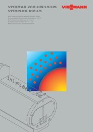
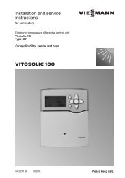
Product description2.11 Monitoring equipmentMonitoring by transmitters for oil pressure, coolingwater temperature, exhaust gas temperature, heatingwater temperature and speed including transmittersformin. cooling water pressure, minimum lubricating oillevel and safety temperature limiter including thecabling to the switching cabinet.Fig. 2Monitoring equipmentOverall legend:1 cogeneration module (scope of delivery)2 provided by the customer10 deflagration guard (biogas)11 safety valve (heating water)12 heating water pump13 return temperature controller14 Heating water return15 heating water forward feed16 power current 400 V, 50 Hz17 mixed cooling water forward feed18 mixed cooling water return19 mixed cooling water pump21 safety valve (motor cooling water)22 oil cooler23 cooling water pump24 membrane expansion unit25 cooling water heat exchanger26 dirt trap27 shut-off valve31 exhaust gas heat exchanger32 sound absorber33 condensate water output34 exhaust gas output35 catalyst41 lambda regulating valve42 magnetic valve43 zero pressure regulator44 gas connection45 gas filter (provided loosely by the customer)46 gas ball cock with thermal safety valve47 sealing control51 added lubricating oil tank (fresh oil)52 automatic refill for lubricating oil with leveldisplay61 lubricating oil return (from oil screen)62 crank space ventilation63 oil screen64 combustion air65 air filter66 gas-air mixer67 alternator68 exhaust gas collection line69 engine70 speed controller and butterfly valve71 turbocharger72 intercooler (1st stage)73 intercooler (2 nd stage)74 blow-off valve for low-temperature circuit80 exhaust ventilator cowl81 exhaust air82 additional air83 sound-absorbing hoodMeasuring pointsEIA alternator-display monitoringES alternator output controlLS level controlLZA minimum level controlP pressurePC pressure regulatorPI pressure indicatorPO visual pressure indicatorPZA- minimum pressure shut-offPZA+ maximum pressure shut-offSC speed controllerSTB safety temperature limiterSZA- underspeedT temperatureTA exhaust air temperature before theventilatorTC temperature controllerTI temperature indicatorTZA+ alternator winding temperaturemonitoringXC lambda probe* Provided loose for assembly by the customer** optional equipment5368 443 09/200914 ESS Energie Systeme & Service GmbH VITOBLOC 200 EM-140/207
Product description2.12 Switching cabinetThe switching cabinet is mounted on the cogenerationmodule. All the following components includingcabling are in the cogeneration module.2.12.1 Brief descriptionAlternator power circuit4-pole power circuit with thermal/magnetic trigger, manual operationAlternator contactSet of current transformersCalibrated kWh current meter including transformerControl, monitoring and auxiliary drive componentSynchronisation and mains monitoringControl system and relay for the KW pump, starter, exhaust ventilator cowl and gas laneOutput regulation for warm running, constant/sliding value with ramp function when starting and stopping speed andoutput regulation with the electronic speed regulator functioning with an electrical actuator and mixed butterfly valve.230 V socket for servicingKey switch for safety switch-off (emergency stop)Battery chargerMicroprocessor controlWindow technique display for showing operating and off-normal values2 separate microprocessors (one each for the start-stop routine for parallel and stand-by operation including lambdaregulation and mains protection/mains monitoring)Separate password-protected access levels for EVU, parametering and manual operationPotential-free inputs for remote start, constant/sliding value regulation and substitute network startHistory memory for recording the minimum/maximum analogous values for streamlining operationFault memory for undeletable recording of complete chains of faults with operating parameters for systematic faultanalysisDDC interface via RS 232 with 3964R protocol (RK 512 should be put together by the customer as per thehardware/software provided by the customer) – other interfaces at requestOperating and centralised fault indication with potential-free contactsOption of remote data monitoringTab. 3The components of the switching cabinet5368 443 09/2009VITOBLOC 200 EM-140/207 ESS Energie Systeme & Service GmbH 15
Product description2.12.2 Basic circuit diagram of the electrical connections in parallel and stand-by operationFig. 3The schematic diagram of electrical connections in parallel operationFig. 4The schematic diagram of electrical connections in parallel and stand-by operation5368 443 09/200916 ESS Energie Systeme & Service GmbH VITOBLOC 200 EM-140/207
Product description2.13 Check-list for stand-by operationThe following items should be discussed with themanufacturer of the block-type thermal power plantand resolved when planning the systems of the blocktypethermal power plant in stand-by operation orsystems in accordance with VDE 0108.● The operating mode of the substitute networksystem?At least one single-line diagram should besubmitted for resolution. The switches to betriggered by the block-type thermal power plantshould be stated or marked in the plan.● What loads have to be supplied?A list of the highest-performance consumers givingthe outputs and currents. Then the manufacturer ofthe block-type thermal power plant defines theacceptable load connection. It might be necessaryfor the customer to provide a load-shedding switchafter consultation.● Protective measure: The customer should checkthe selectivity of the fuses.● The acceptable hot-water return temperature withblock-type thermal power systems for stand-byoperation is no more than 65° C in parallel andstand-by operation. That means that these blocktypethermal power systems are not only suited tosupplying absorption refrigerating machines.● The main gas magnetic valve, the network sectionswitch and the corresponding open-circuit shuntrelease have to have a battery-buffered voltagesupply.230 V supply voltage for the main gas magneticvalve or network section switch is not permitted.The main gas magnetic valve and the drive of thenetwork section switch are not supplied by theblock-type thermal power plant.● The triggering and feedback from the switches areplaced with the customer’s electrician and thesupplier of the block-type thermal power plant.● If the higher-level regulation provided by thecustomer cannot guarantee automatic restartwithout malfunctions after mains malfunction, thefault messages from the plant systems provided bythe customer such as heating or ventilation maymake the block-type thermal power plant switch offif there is a mains failure due to such things as alack of heat reduction. In this case, the higherlevelregulation should be equipped with aseparate uninterruptible power supply.● Stand-by operation should be tested immediatelyafter starting up the block-type thermal power plantwith everyone involved. If this is not possible, it willbe necessary to have a second date that will becharged according to expenditures.● Sprinkler pump supply is subject to the morestringent VdS regulations so that is cannot beassured with the normal design of a block-typethermal power plant.● The appropriate process control technique (suchas multi-module management) should be providedwith active-power load distribution if severalcogeneration modules are used in stand-byoperation.● We do not recommend switching the block-typethermal power plant up to any emergency-powerdiesel alternator because the gas and dieselengines have different regulating characteristics.The basic prerequisite would be that theemergency-power diesel alternator iscorrespondingly equipped for parallel operationwith other power alternators (such as regulatingalternator voltage or digital inputs for active-powerload distribution on the control system of the dieselalternator).5368 443 09/2009VITOBLOC 200 EM-140/207 ESS Energie Systeme & Service GmbH 17
Service and maintenance3 Service and maintenanceThere are what is known as consequential costs“connected to operation” for the cogeneration modulein the form of inspection, service and maintenance.The cogeneration module is exposed to many factorssuch as wear and tear, ageing, corrosion andthermal/mechanical loads due to intended operation.DIN 31051 designates this as wear. The design of thecomponent parts of the cogeneration module givesthem a wear reservoir that guarantees reliableoperation for the cogeneration module in accordancewith the operating conditions up to the impairment oftheir functionality. Afterwards, these parts should bereplaced according to specific wear and limited-timecomponents.Definition of "wear parts" according to DIN 31051Wear parts are parts that are unavoidably subject towear due to operation and that are engineered forreplacement. They essentially include spark plugs andair/oil filters. This replacement is done on a regularbasis are forms what are known as “inspection andservice” (regular service).Definition of "limited-time components" accordingto DIN 31051Limited-time components are parts whose service lifeis shorter than the service life of the entirecogeneration module and cannot be extended bytechnically feasible and commercially reasonablemeans. They essentially include cylinder heads,bearing shells, catalysts and heat transfer units. Theyare replaced at longer intervals depending upon theresults of inspections. This is where we talk ofmaintenance.Having authorised personnel correctly service thecogeneration module is very important for its warrantyand for it to function without any problems. Onlyoriginal parts and the operating resources (such aslubricating oil) approved by the manufacturer of theblock-type thermal power plant may be used. Theoperator is responsible for guaranteeing andcomplying with the regulations for operatingresources.IMPORTANTService should be carried out at leastonce a year and the cooling watershould be changed no later than every2 years.NOTEThe expected service life of thecogeneration module is no less than 10years if it is regularly serviced andmaintained.5368 443 09/200918 ESS Energie Systeme & Service GmbH VITOBLOC 200 EM-140/207
Service and maintenance3.1 Service and maintenance list5368 443 09/2009Tab. 4service levelA/B/CA/B/Cservice workoil changereplace oil filterA/B/C clean the lubricating tank with EM-18/36 (only tanks built in 2002)A/B/C check oil washdown on EM-18/36 (only tanks built in 2002)A/B/CA/B/CA/B/CA/B/CA/B/CA/B/CA/B/CA/B/CA/B/CA/B/CA/B/CA/B/CA/B/CA/B/CA/B/CA/B/CA/B/CA/B/CB/CB/CB/CB/CB/CB/CB/CB/CB/CB/CB/CB/CCCCCCService Listcheck battery state and charge voltage / or fill distilled waterchange air filter insert and clean the air filter casingmeasure the valve play or adjust wherever necessarycheck the cooling water pressure or refill and vent wherever necessarycheck or clean the condensate drain / check the neutralisationcheck the butterfly valve and rod assembly/tooth belt and lubricate wherever necessarycheck ignition cables and spark plug socketcheck the spark plugs and adjust the electrode spacecheck the point in time of ignitionstart/stop routine/function checkrecord or print out the general operating datacheck the exhaust gas counterpressure after the enginemake a general check of sealing/random samples to see if screws are tightcheck the function of automatic oil refilling / check the level adjustmentopen the oil refilling cock / mark the oil levelset the service interval backgeneral module cleaning / disposing of the cleansers and oil tinsgeneral visual inspection of the switching cabinet componentscheck the tooth belt for the camshaft, tension roller and water pump (only EM-18/36)check antifrost concentration and refillcheck the compression (every service level with EM-18/36)check and clean the alternator air suction / check the power cableschange the spark plugs (change with EM-18/36, EM-199/263 and EM-199/293 with servicelevel A)test the reverse performance monitoringcheck the gas lane for sealing and check the gas filtertest the overspeed shut-offtest the excess exhaust gas temperature shut-offtest the excess cooling water temperature shut-offtest the minimum oil pressure shut-offcheck the power cable on the alternatorchange the ignition cablecheck the lambda probe and change wherever necessaryclean the gas mixerchange the cooling water (within 24 months) and check the pressure expansion vesselcheck the crankshaft space ventilation and replace wherever necessaryVITOBLOC 200 EM-140/207 ESS Energie Systeme & Service GmbH 19
Service and maintenancemaintenance leveli1/i2/i3/i4i2i2/i4i2/i4i2/i4i2/i4i4i4maintenance workclean the exhaust gas heat transfer unitreplace the cylinder headcheck the plate heat transfer unit and replace wherever necessarystartercheck the catalyst and replace wherever necessarychange the ignition coilsoverhaul the engineoverhaul the alternator bearingTab. 5Maintenance list5368 443 09/200920 ESS Energie Systeme & Service GmbH VITOBLOC 200 EM-140/207
<strong>Technical</strong> Data4 <strong>Technical</strong> DataAll subsequent planning and operating data refer to acogeneration module.You can find detailed instructions on planning anddesign in the "Natural Gas Block-Type Thermal PowerPlant Series – Project Management".4.1 Operating parameters for the cogeneration module5368 443 09/2009Operating parameters for the cogeneration moduleContinuous operation 1) in paralleloperationVitobloc 200 EM-140/207electrical output cannot be overloaded kW 70 105 140heat output tolerance 5% kW 130 171 207fuel usage tolerance 5% kW 227 310 384current characteristic value in accordance with AGFW FW308 (electricaloutput/thermal output)Primary energy factor ENEV 2007 fPE 0.72primary energy savings PEE in accordance with Directive 2004/8/EC supportfor cogenerationefficiency in parallel operation50%load75%load100%load0.676% 26.0electrical efficiency % 30.8 33.8 36.5heat efficiency % 57.3 55.0 53.9total efficiency % 88.1 88.8 90.4Energy generationelectrical energy (three-phase) voltage V 400frequency Hz 50own electrical requirements2) kW 2.7heat energy (heat) without substitute network function forward/returntemperatureheat energy (heat) with substitute network functionFuels and filling amountsforward/returntemperature° C 90/70° C 90/65quality of fuel, lubricating oil, cooling water and heating waterrefer to the currentoperational regulationsfilling quantity lubricating oil ltr. 21added fresh oil tank ltr. 70cooling water ltr. 85heating water ltr. 10gas connecting pressure 3) mbar 25 - 50Heat generation (heating)return temperature in front of the module min./max. ° C 60/70standard temperature difference return/forward feed k 20heating water volume flow standard m³/h 8.9maximum acceptable operating pressure bar 16pressure loss at standard flowthrough in the module standard bar 0.15Pollution emissions4) in accordance with the<strong>Technical</strong> Instruction for Air 2002NOx content measured as NO 2 mg/Nm³ < 125CO contentmg/Nm³mg/kWh< 150< 129formaldehyde CH 2 O mg/Nm³ < 60VITOBLOC 200 EM-140/207 ESS Energie Systeme & Service GmbH 21
<strong>Technical</strong> DataSound intensity level 1 free field meter away in accordance with DIN 45635(tolerance to the specified values 3 dB(A))exhaust air noise measured 1 meter after the channelmachine with sound-absorbing hood dB (A) 74exhaust ventilator without sound absorber dB (A) 71cowl 5)exhaust gas 6) without sound absorber dB (A) 83with sound absorber dB (A) 57Combustion air and ventilationmodule’s radiating heat without connecting line kW 17installation room ventilation additional air volume flow m³/h >3,400targeted exhaust airvolume flowmaximum exhaust airvolume flowm³/h 3,000m³/h 4,500combustion air volume flow at 25 °C and 1,000 mbar m³/h 391additional air temperature min./max. ° C 10/25temperature difference additional air/exhaust air k < 20pressing of the built-in exhaust ventilatorcowlExhaust gasmax. Pa 500exhaust gas volume flow, moist at 120 °C m³/h 608exhaust gas mass flow, moist kg/h 520exhaust gas volume flow, dry 0 % O 2 (0 °C; 1012 mbar) Nm³/h 336maximum acceptable counterpressure depending upon module mbar 151) output data in accordance with DIN ISO 3046 Part 1(at 1,000 mbar of air pressure, air temperature 25° C, relative humidity 30% and cos φ =1)All other data for the module apply to parallel operation; data for other installation conditions at request2) cooling water pump, ventilator, battery charger and control transformer3) Gas connecting pressure is in accordance with DVGW-TRGI 1986/96 of the gas flowing pressure at the beginning of the module’sgas regulating route4) Emission figures after the catalyst with reference to dry exhaust gas5) at 500 Pa pressing, thermostat stage 100%6) insert damping of the secondary exhaust gas sound absorber at requestTab. 6Operating parameters of a complete cogeneration module5368 443 09/200922 ESS Energie Systeme & Service GmbH VITOBLOC 200 EM-140/207
<strong>Technical</strong> Data4.2 <strong>Technical</strong> data of a complete cogeneration module<strong>Technical</strong> data for the cogeneration moduleVitobloc 200 EM-140/207engine with accessoriesgas spark-ignition engine manufacturer MANengine modelE 2876 LEfunctioning4-strokenumber of cylinders/arrangement6 in a rowbore/stroke mm 128/166displacement ltr. 12.82speed min -1 1500mean piston speed m/s 8.3compression ratio 12 : 1mean effective pressure bar 9.36standard output1) cannot be overloaded kW 150specifications full load consumption tolerance 5% kWh/kWh mech 2.62gas consumption for instance, at Hi = 10Nm³/h 39.3kWh/m³lubricating oil quantity in the oilpan ltr. 28lubricating oil consumption (mean) g/h approx. 50engine weight (about) kg 830Heat exchanger system for the engine cooling system (engine block and lubricating oil)heat output tolerance 5% kW 128cooling water temperature intake/output ° C 82/88cooling water volume flow m³/h 20.8Exhaust gas heat exchangerheat output tolerance 5% kW 79exhaust gas temperature intake/output ° C approx. 590 / < 120cooling water temperature intake/output ° C 88/92pressure loss on the exhaust gas side mbar < 10material of pipes 1.4571materials of exhaust gas head intake 1.4828output 1.4571material of the water cooling jacket ST 50Plate heat exchangerheat output kW 207cooling water temperature intake/output ° C 92/82heating water temperature intake/output ° C 70/90pressure loss bar 0.15Material of plates 1.4404Rated widthsexhaust gas connection (AA) from the cogeneration module andDN 100 / PN 10pipe connectioncondensation water connection (AKO) and pipe connection pipe ø22 x 1.2heating water forward/return (V/R) and pipe connection DN 50 / PN 16gas connection (GAS) and pipe connection gas ball cock Rp 1/2”5368 443 09/2009VITOBLOC 200 EM-140/207 ESS Energie Systeme & Service GmbH 23
<strong>Technical</strong> DataAlternatormodel output kVA 165three-phase current voltage/frequency V / Hz 400/50speed min -1 1500efficiency at the rated output of the module and cos φ = 1 % 95.4rated current A 216.5continuous short-circuit current A 3-5 times the rated currentmaximum acceptable loadA 61.9applicationstator circuit-breakerstarambient temperature max. ° C 40protection class IP 23Time constants in secondsopen circuit transient Td'o sec. 2.80short-circuited circuit transient Td' sec. 0.10short-circuited circuit subtransient Td'’ sec. 0.010with short-circuited field Ta sec. 0.015Cabling to the cogeneration terminal boxNSHV protection (recommended) A 300Minimum required design for correctly connecting the cogeneration system 2)network connection to the NSNV, system-tie field ortransformerX1: L1,L2,L3, N PE H07 RNF 5 x 1 x 120 mm²remote selection for "heat operation" 100% outputprovided by the customerX1: terminal 40 / 41feedback (potential-free contact) module "ready" X5: terminal 1 / 2feedback (potential-free contact) module "operation" X5: terminal 3 / 4Ölflex 12 x 1.5 mm²feedback (potential-free contact) module "malfunction" X5: terminal 5 / 6heating water pump dialling 3) (potential-free contact) X5: terminal 9 / 10heating-water regulating valve (return rise) X5: terminal 16 / 17 / 18 / PE Ölflex 4 x 0.75 mm²heating water pump 230 V /10 A 3) X5: terminal 21 / / / PE Ölflex 3 x 1.5 mm²additional PT 100 sensor in the overall heating waterreturn for optional module selection and deselectionX1: terminal 44 / 45 Ölflex 2 x 1.5 mm²earthing cable from the module to thepotential-equalisation rail provided by the customerearthing connection on themodule framedimensioning as percustomer’s conditionsExtended plant design with "stand-by operation"network measuring voltage in front of the system-tiecircuit-breakerX1: terminal 7 / 8 / 9 / N / PE Ölflex 5 x 1.5 mm²system-tie circuit-breaker feedback is on(signal from the NSHV or from the system-tie field)X1: terminal 12 / 13system-tie circuit-breaker feedback is off(signal from the NSHV or from the system-tie field)X1: terminal 14 / 15Ölflex 5 x 1.5 mm²select stand-by operation 4) X1: terminal 38 / 39 Ölflex 3 x 1.5 mm²switch-on command for the system-tie circuit-breakerX5: terminal 7 / 8"NK switch release" (potential-free contact)Ölflex 3 x 1.5 mm²1) Output data in accordance with DIN ISO 3046 Part 1(at 1,000 mbar of air pressure, air temperature 25° C, relative humidity 30% and cos φ =1)All other data for the module apply to parallel operation; data for other installation conditions on request2) This cable list constitutes the minimum design needed for correctly connecting a block-type thermal power plant (only used as a guideline) Theelectrical company doing the work has the responsibility for correct cabling which should be carried out according to the local requirements andrelevant VDE and EVU regulations.3) The heating water pump in 230 V design can be clamped directly. The customer has to provide the power circuit with a pump design of 400 V.The control equipment should be chosen to be potential-free from the module control system.4) External control engineering makes the selection for stand-by operation after the customer’s load shedding. The selection can be madeautomatically inside of the module, but without monitoring load shedding.Tab. 7<strong>Technical</strong> data of a complete cogeneration module5368 443 09/200924 ESS Energie Systeme & Service GmbH VITOBLOC 200 EM-140/207
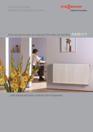
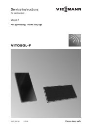
<strong>Technical</strong> Data4.3 Dimensions, Weights and ColoursDimensions of the cogeneration moduleFrame dimensionsIncluding soundabsorbinghoodand exhaust ventilatorcowllength mm 3,400 4,250width mm 900 940height (without bases) mm 1,700 1,720The weight of the cogeneration moduleempty weight (about) kg 3,420operational weight (about) kg 3,620Coloursengine and alternator light grey (RAL 7035)frame anthracite grey (RAL 7016)switching cabinetsound-absorbing hoodVitosilverVitosilverconnections design standard sizeAA exhaust gas output flange EN 1092-1 DN 100 / PN 10AKO condensate water drainage pipe DIN EN 10220 ø22 x 1.2Gas gas intake gas ball cock DIN 2999 Rp 1 ½”V/R heating forward/return flange EN 1092-1 DN 50 / PN 16AL exhaust gas output flange — 550 x 550 P20Tab. 8Dimensions, weights, colours and connections5368 443 09/2009Fig. 5The dimensions and connections of the Vitobloc 200 EM-140/207 cogeneration module (dimensions in mm);The ventilator box already mounted on the back side can be disassembled for mounting the module.VITOBLOC 200 EM-140/207 ESS Energie Systeme & Service GmbH 25
<strong>Technical</strong> Data4.4 InstallationYou can find detailed instructions on design in the"Natural Gas Block-Type Thermal Power Plant Series– Project Management" and in the relevant assemblyinstructions.You have to bear the items below in mind for installingthe cogeneration module:- A blocked clearance as per page 27, Figure 6 inthe installation plan should be kept for operatingand servicing.- At on-site installation, ensure that the modulebases are unscrewed to a clearance of at least 9–11 cm.- These dimensions are needed up to a simple pipelength of 10 meters; otherwise, it will be necessaryto make a separate calculation.- We recommend dimensioning the gas connectinglines for the block-type thermal power plant to usethis lane as buffer storage. This can be used tointercept fluctuations in pressure with boilercircuits.- We recommend using a calibrated gas meter witha G65 design.- The exhaust air ventilator box can bedisassembled for installing the cogenerationmodule. Please let us know before delivery.- The exhaust air can be carried away on all sidesof the exhaust air ventilator box. The connectingsleeves for conducting the exhaust air can bemounted on the specific point.- It should not drop below the dewpoint in theexhaust gas system. Any condensateaccumulating should be continually drained. Awater reservoir should be provided on thecondensate output.We recommend separate exhaust gas conductionfor every cogeneration module with multiplemodule systems. If you use a collecting exhaustgas line, it is necessary to reliably prevent theexhaust gas from flowing back into anycogeneration modules not in operation with anengine shut-off valve that is 100% sealed toexhaust gas.- Condensate flows out of the cogeneration modulewhen starting in the cold state. Neutralisation isnot necessary due to exhaust gas purification inaccordance with ATV A251 (Nov. 1998). A waterreservoir (siphon loop) should be provided with aneffective water column height corresponding to theexhaust gas system pressure (a maximum of 150mm WS) to keep the exhaust gas from flowing outthrough the condensate drain.- The exhaust gas condensate should be disposedof in accordance with applicable regulations.4.5 Start-stop ratioThe module should be at least 120 min in operationper start (approximately 2:1 ratio of the number ofoperating hours to the starts). Early wear and tear inthe starting equipment from shorter times are causedby operation and are not a defect.4.6 Ecotax in GermanyYou have to register your block-type thermal powerplant with your main customs office before starting itup in Germany so that your block-type thermal powerplant can be exempted from the petroleum (naturalgas) and electricity tax. This provides a substantialimprovement of 10%-35% in economic efficiency.Metering equipment may be required for this.NOTEAll electricity generated in Germany viacogeneration has been supported sinceJanuary of 2009 (2009 CogenerationLaw).5368 443 09/200926 ESS Energie Systeme & Service GmbH VITOBLOC 200 EM-140/207
<strong>Technical</strong> DataFig. 6 Sample installation plans – description without fittings and safety equipment (dimensions in mm )EM-18/36EM-50/81EM-70/115EM-140/207Vitobloc 200EM-199/263EM-199/293EM-238/363EM-401/549EM-363/498A 1,000 mm 1,000 mm 1,000 mm 1,000 mm 1,000 mm 1,000 mmB 1,200 mm 1,400 mm 1,600 mm 2,000 mm 2,000 mm 2,000 mmC 4,140 mm 5,240 mm 6,040 mm 6,600 mm 7,450 mm 7,000 mmD 1,940 mm 2,840 mm 3,440 mm 3,600 mm 4,450 mm 4,000 mmE 1,300 mm 1,800 mm 1,800 mm 2,020 mm 2,000 mm 2,020 mmF 2,500 mm 2,800 mm 2,800 mm 4,000 mm 3,500 mm 4,000 mmG 800 mm 800 mm 800 mm 1,100 mm 1,500 mm 1,500 mmH 890 mm 900 mm 940 mm 1,650 mm 1,650 mm 1,650 mmI 2,490 mm 2,500 mm 2,540 mm 3,850 mm 4,650 mm 4,650 mmTab. 9Installation dimensionsMinimum base dimensionsVitobloc 200 EM-140/207L 2,680 mmW 1,040 mmH 150 mmFig. 7The block-type thermal power plant with the base5368 443 09/2009IMPORTANTPlease pay attention to the frame overhangingthe base when installing the block-typethermal power plant.VITOBLOC 200 EM-140/207 ESS Energie Systeme & Service GmbH 27
Important information on planning and operation5 Important information on planning and operation5.1 MalfunctionsMalfunctions or consequential damage due tounacceptable operating conditions are neithercovered by the warranty nor any service contract.Your operational safety will be boosted if you complywith the items below:Design● Avoid clocking on-off operation and provide buffermemoryThe ratio of operating hours to starts has to be atleast greater that 2 (in other words, at least twohours of operation per start). The larger the ratio ofoperating hours: starts, the better.Installation space● Provide exhaust gas and exhaust air dampers insound-critical objects and always allow for elasticconnections (i.e., compensators).● Make sure that the exhaust gas and exhaust airlines are correctly dimensioned and conducted(because of pressure losses, rated widths and flowroaring).● Make sure that it is installed on the looselysupplied module bases for structure-borne noisedecoupling.● Do not install in the same room as a NH3refrigerating machine.Heating● Guarantee constants and sufficient heating watervolume flow● Prevent emergency shutdown due to excessiveheating water return temperatures The hot waterreturn temperature may not be in excess of 65° Ceither in stand-by operation or in parallel operation.● Any return temperature increasing mechanismshould be installed as near to the cogenerationmodule as possible.● Provide optional heat quantity meters in the returntemperature increasing mechanism to ascertain theheat energy generated.● The stand-by operation function is not inconnection with operating an absorptionrefrigerating machine.Exhaust gas● Sufficiently dimension the exhaust gas crosssection(no more than 10 m/s of the flow speed).● Use a suitable qualification approval exhaust gaspipe (with a wall thickness of at least 1 mm madeof stainless steel and connections pressureresistantto pulsation to 4,000 Pa).● Free drainage should be provided for thecondensate water with at least a 3% inclinationover the siphon (U pipe) at a height ofapproximately 150 mm for keeping exhaust gasfrom escaping from the condensate water drain.Ventilation● Provide cooling and combustion air that is notpreheated and free of dust/halogen.● Provide sufficient fresh air supply and reliably carryoff warm exhaust air.● Provide separate air inlet suction in the swimmingpool (if the air contains chlorine).Fuel● Maintain gas flow pressure of 25-50 mbar and amethane number ≥ 80.● Overdimension the inlet as a pressure buffer.● Optional gas quantity meters generally measurethe operational cubic meters. These readingsshould be converted into normal cubic meters (zNumber) in accordance with the guidelines ofDVGW-TRGI G 600.Electro● The block-type thermal power plant generateselectric power at 400 V. For reasons of safety, ithas sensitive electrical nozzle protectionequipment that reacts to asynchronous networkloads in the customer’s network in accordance withthe regulations. Safety shutdowns are not amalfunction of the block-type thermal power plant.● If the electrical loads in stand-by operation areincorrectly dimensioned, this may causeemergency shutdown due to overloading (inductiveor capacitive starting currents are as much as 20times the rated current, which can overload theblock-type thermal power plant).● Always avoid shutting down under full load sincethe component parts are subject to maximummechanical loads.● The cogeneration modules have to be connectedto the equipotential bonding rail provided by thecustomer via an earthing cable.Service + Operating resources● Regular service and care by qualified personnel.We recommend signing a service contract.● Clean up drip leaks, dispose of old oil correctly andregularly check the exhaust gas condensate linesto see if they are in good working order.● Disconnect the batteries if there are longerinterruptions to operations when shutting down themodule and preserve the module when is shutdown for longer than 24 hours.5368 443 09/200928 ESS Energie Systeme & Service GmbH VITOBLOC 200 EM-140/207
Index6 IndexAAlternator power circuit ........................................... 15BBasic circuit diagram ............................................... 16Basic frame ............................................................. 10CColours ................................................................... 25Continuous output in parallel operation ..................... 5Cooling water heat transfer unit .............................. 11Coupling .................................................................. 10DDesign ..................................................................... 28Dimensions ............................................................ 25EElectro ..................................................................... 28Emission values ........................................................ 5Emissions of pollution ............................................... 5Energy balance sheet ............................................... 6Exhaust gas ............................................................ 28Exhaust gas front silencer ....................................... 10Exhaust gas purification system ............................. 12Exhaust ventilator cowl ........................................... 12FFlange coupling ...................................................... 10GGas spark-ignition engine ....................................... 10General Statements .................................................. 4HHeat transfer system ............................................... 11Heating ................................................................... 28IInstallation ............................................................... 26Installation space .................................................... 28MMicroprocessor control ............................................ 15Monitoring equipment ............................................. 14NNoise protection elements ...................................... 10OOperating resources ............................................... 28PPiping ...................................................................... 11Plate transfer heat unit ............................................ 11Product description ................................................... 7RRepair ..................................................................... 18SSample installation plans ........................................ 27Service .................................................................... 28Service and repair ................................................... 18Sound insulation hood ............................................ 12Stand-by operation .................................................... 5Switching cabinet .................................................... 15T<strong>Technical</strong> data ........................................................ 21Three-phase synchronous alternator ...................... 10VVentilation ............................................................... 28WWeights ................................................................... 25Zz-number ................................................................. 285368 443 09/2009VITOBLOC 200 EM-140/207 ESS Energie Systeme & Service GmbH 29
Conformity declaration7 Conformity declaration5368 443 09/200930 ESS Energie Systeme & Service GmbH VITOBLOC 200 EM-140/207
Brief instructions8 Brief instructions5368 443 09/2009VITOBLOC 200 EM-140/207 ESS Energie Systeme & Service GmbH 31
ENERGY• gas-fuelled enginesystems• cogenerationcompetence centreSYSTEMS• mobile units• software solutions• switching cabinetsystemsSERVICE• start-ups• service strategies• training coursesSubject to change without noticeESS Energie Systeme & Service GmbHCelsiusstraße 9D-86899 Landsberg am LechTel: 08191 / 9279-0Fax: 08191 / 9279-23info@ess-landsberg.dewww.ess-landsberg.de799 000 0205368 443 09/200932 ESS Energie Systeme & Service GmbH VITOBLOC 200 EM-140/207