"A" Ductable Liquid Chillers with Integrated Hydronic Module
"A" Ductable Liquid Chillers with Integrated Hydronic Module "A" Ductable Liquid Chillers with Integrated Hydronic Module
6 - APPLICATION DATA6.1 - Unit operating rangeEvaporator Minimum °C Maximum °CWater entering temp. (at start-up) 7.8 * 30Water leaving temp. (in operation) 5 ** 10Water entering temp. (at shut down) - 50CondenserEntering air temp. -10*** 46***This volume is required to obtain temperature stability andprecision.To achieve this volume, it may be necessary to add a storagetank to the circuit. This tank should be equipped with baffles toallow mixing of the fluid (water or brine). Please refer to theexamples below.Do not exceed the maximum operating temperature.* For a system requiring operation below 7,8°C, contact Carrier SA.** For a system requiring operation below 5°C, anti-freeze must be added to theunit.*** Maximum outside temperature: For transport and storage of the 30RY unitsthe minimum and maximum allowable temperatures are –20°C and +55°C. Itis recommended that these temperatures are used for transport by container.BadGood6.2 - Evaporator water flow rates30RY Evaporator water flowMin. flow rate Max. flow rate* Max. flow rate**Single pump Dual pumpl/s l/s l/s l/s017 0.58 1.7 0 1.7021 0.70 1.8 0 1.9026 0.81 1.9 0 2.2033 1.10 2.0 0 3.0040 1.20 3.5 4.4 3.7050 1.19 4.0 5.2 4.6060 1.46 4.4 6.0 5.8070 1.66 4.6 6.4 6.4080 1.92 5.5 6.8 7.3* Maximum flow rate at an available pressure of 50 kPa (unit with hydronicmodule).** Maximum flow rate at a pressure drop of 100 kPa in the plate heat exchanger(unit without hydronic module).6.3 - Minimum water flow rateIf the installation flow rate is below the minimum flow rate,recirculation of the evaporator water flow may take place,leading to the risk of excessive fouling.6.4 - Maximum evaporator water flow rateThis is limited by the permitted evaporator pressure drop.Also, a minimum evaporator ∆T of 2.8 K must be guaranteed,which corresponds to a water flow rate of 0.9 l/s per kW.6.5 - Water loop volume6.5.1 - Minimum water loop volumeThe minimum water loop volume, in litres, is given by thefollowing formula:Volume = CAP (kW) x N* = litres, where CAP is the nominalcooling capacity at nominal operating conditions.Application N*Air conditioning30RY 017-040 3.530RY 050-240 2.5Industrial process cooling30RY 017-080(See note)NOTE: For industrial process cooling applications, wherehigh stability of the water temperature levels must beachieved, the values above must be increased.6.5.2 - Maximum water loop volumeUnits with hydronic module incorporate an expansion tank thatlimits the water loop volume. The table below gives themaximum loop volume for pure water or ethylene glycol withvarious concentrations.30RY 017-033 30RY 040-080(in litres)(in litres)Pure water 400 600Ethylene glycol 10% 300 450Ethylene glycol 20% 250 400Ethylene glycol 35% 200 300Entering air temperatureEG: Ethylene glycol6.6 - 30RY unit operating range at full and part load˚C464544.5440-10BadGood0 1 2 3 4 5 6 7 8 9 10 ˚CEvaporator water leaving temperatureNotes1 Evaporator ∆T = 5 K2 The evaporator and the hydronic circuit pump are frost protected downto -20°C.Operating range with required anti-freeze solution and special Pro-Dialogcontrol configuration12
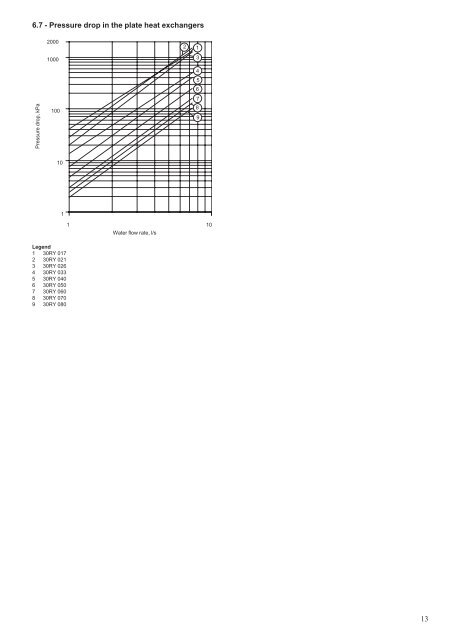
6.7 - Pressure drop in the plate heat exchangers200010002134Pressure drop, kPa100567891011 10Water flow rate, l/sLegend1 30RY 0172 30RY 0213 30RY 0264 30RY 0335 30RY 0406 30RY 0507 30RY 0608 30RY 0709 30RY 08013
- Page 1: 30RY 017-080 "A"Ductable Liquid Chi
- Page 4 and 5: 1 - INTRODUCTIONPrior to the initia
- Page 6 and 7: During refrigerant removal and stor
- Page 8 and 9: Checks before system start-upBefore
- Page 10 and 11: 4 - PHYSICAL DATA30RY 017 021 026 0
- Page 14 and 15: 7 - ELECTRICAL CONNECTION30RY 017-0
- Page 16 and 17: 9 - WATER CONNECTIONSFor size and p
- Page 18 and 19: Typical hydronic circuit diagram (3
- Page 20 and 21: When the circuit is cleaned, read t
- Page 22 and 23: Accessory reference number:30RY-017
- Page 24 and 25: Pressure12 - MAINTENANCEAny technic
- Page 26 and 27: Bar Saturated bubble Saturated dew
- Page 28 and 29: Service CCarry out the operations l
- Page 30 and 31: Unit start-upChilled water pump sta
- Page 32: Order No.: 13427-76, 04.2002 - Supe
6.7 - Pressure drop in the plate heat exchangers200010002134Pressure drop, kPa100567891011 10Water flow rate, l/sLegend1 30RY 0172 30RY 0213 30RY 0264 30RY 0335 30RY 0406 30RY 0507 30RY 0608 30RY 0709 30RY 08013


